EP3389112B1 - Batteriemodul mit verbesserter rahmenstruktur - Google Patents
Batteriemodul mit verbesserter rahmenstruktur Download PDFInfo
- Publication number
- EP3389112B1 EP3389112B1 EP17839863.2A EP17839863A EP3389112B1 EP 3389112 B1 EP3389112 B1 EP 3389112B1 EP 17839863 A EP17839863 A EP 17839863A EP 3389112 B1 EP3389112 B1 EP 3389112B1
- Authority
- EP
- European Patent Office
- Prior art keywords
- plate
- battery module
- cells
- lower plate
- frame assembly
- Prior art date
- Legal status (The legal status is an assumption and is not a legal conclusion. Google has not performed a legal analysis and makes no representation as to the accuracy of the status listed.)
- Active
Links
Images


Classifications
-
- H—ELECTRICITY
- H01—ELECTRIC ELEMENTS
- H01M—PROCESSES OR MEANS, e.g. BATTERIES, FOR THE DIRECT CONVERSION OF CHEMICAL ENERGY INTO ELECTRICAL ENERGY
- H01M10/00—Secondary cells; Manufacture thereof
- H01M10/04—Construction or manufacture in general
- H01M10/0486—Frames for plates or membranes
-
- H—ELECTRICITY
- H01—ELECTRIC ELEMENTS
- H01M—PROCESSES OR MEANS, e.g. BATTERIES, FOR THE DIRECT CONVERSION OF CHEMICAL ENERGY INTO ELECTRICAL ENERGY
- H01M10/00—Secondary cells; Manufacture thereof
- H01M10/42—Methods or arrangements for servicing or maintenance of secondary cells or secondary half-cells
- H01M10/4207—Methods or arrangements for servicing or maintenance of secondary cells or secondary half-cells for several batteries or cells simultaneously or sequentially
-
- H—ELECTRICITY
- H01—ELECTRIC ELEMENTS
- H01M—PROCESSES OR MEANS, e.g. BATTERIES, FOR THE DIRECT CONVERSION OF CHEMICAL ENERGY INTO ELECTRICAL ENERGY
- H01M50/00—Constructional details or processes of manufacture of the non-active parts of electrochemical cells other than fuel cells, e.g. hybrid cells
- H01M50/10—Primary casings; Jackets or wrappings
- H01M50/102—Primary casings; Jackets or wrappings characterised by their shape or physical structure
- H01M50/105—Pouches or flexible bags
-
- H—ELECTRICITY
- H01—ELECTRIC ELEMENTS
- H01M—PROCESSES OR MEANS, e.g. BATTERIES, FOR THE DIRECT CONVERSION OF CHEMICAL ENERGY INTO ELECTRICAL ENERGY
- H01M50/00—Constructional details or processes of manufacture of the non-active parts of electrochemical cells other than fuel cells, e.g. hybrid cells
- H01M50/20—Mountings; Secondary casings or frames; Racks, modules or packs; Suspension devices; Shock absorbers; Transport or carrying devices; Holders
- H01M50/202—Casings or frames around the primary casing of a single cell or a single battery
-
- H—ELECTRICITY
- H01—ELECTRIC ELEMENTS
- H01M—PROCESSES OR MEANS, e.g. BATTERIES, FOR THE DIRECT CONVERSION OF CHEMICAL ENERGY INTO ELECTRICAL ENERGY
- H01M50/00—Constructional details or processes of manufacture of the non-active parts of electrochemical cells other than fuel cells, e.g. hybrid cells
- H01M50/20—Mountings; Secondary casings or frames; Racks, modules or packs; Suspension devices; Shock absorbers; Transport or carrying devices; Holders
- H01M50/204—Racks, modules or packs for multiple batteries or multiple cells
- H01M50/207—Racks, modules or packs for multiple batteries or multiple cells characterised by their shape
- H01M50/211—Racks, modules or packs for multiple batteries or multiple cells characterised by their shape adapted for pouch cells
-
- H—ELECTRICITY
- H01—ELECTRIC ELEMENTS
- H01M—PROCESSES OR MEANS, e.g. BATTERIES, FOR THE DIRECT CONVERSION OF CHEMICAL ENERGY INTO ELECTRICAL ENERGY
- H01M50/00—Constructional details or processes of manufacture of the non-active parts of electrochemical cells other than fuel cells, e.g. hybrid cells
- H01M50/20—Mountings; Secondary casings or frames; Racks, modules or packs; Suspension devices; Shock absorbers; Transport or carrying devices; Holders
- H01M50/218—Mountings; Secondary casings or frames; Racks, modules or packs; Suspension devices; Shock absorbers; Transport or carrying devices; Holders characterised by the material
- H01M50/22—Mountings; Secondary casings or frames; Racks, modules or packs; Suspension devices; Shock absorbers; Transport or carrying devices; Holders characterised by the material of the casings or racks
- H01M50/222—Inorganic material
- H01M50/224—Metals
-
- H—ELECTRICITY
- H01—ELECTRIC ELEMENTS
- H01M—PROCESSES OR MEANS, e.g. BATTERIES, FOR THE DIRECT CONVERSION OF CHEMICAL ENERGY INTO ELECTRICAL ENERGY
- H01M50/00—Constructional details or processes of manufacture of the non-active parts of electrochemical cells other than fuel cells, e.g. hybrid cells
- H01M50/20—Mountings; Secondary casings or frames; Racks, modules or packs; Suspension devices; Shock absorbers; Transport or carrying devices; Holders
- H01M50/262—Mountings; Secondary casings or frames; Racks, modules or packs; Suspension devices; Shock absorbers; Transport or carrying devices; Holders with fastening means, e.g. locks
- H01M50/264—Mountings; Secondary casings or frames; Racks, modules or packs; Suspension devices; Shock absorbers; Transport or carrying devices; Holders with fastening means, e.g. locks for cells or batteries, e.g. straps, tie rods or peripheral frames
-
- H—ELECTRICITY
- H01—ELECTRIC ELEMENTS
- H01M—PROCESSES OR MEANS, e.g. BATTERIES, FOR THE DIRECT CONVERSION OF CHEMICAL ENERGY INTO ELECTRICAL ENERGY
- H01M50/00—Constructional details or processes of manufacture of the non-active parts of electrochemical cells other than fuel cells, e.g. hybrid cells
- H01M50/50—Current conducting connections for cells or batteries
- H01M50/572—Means for preventing undesired use or discharge
-
- Y—GENERAL TAGGING OF NEW TECHNOLOGICAL DEVELOPMENTS; GENERAL TAGGING OF CROSS-SECTIONAL TECHNOLOGIES SPANNING OVER SEVERAL SECTIONS OF THE IPC; TECHNICAL SUBJECTS COVERED BY FORMER USPC CROSS-REFERENCE ART COLLECTIONS [XRACs] AND DIGESTS
- Y02—TECHNOLOGIES OR APPLICATIONS FOR MITIGATION OR ADAPTATION AGAINST CLIMATE CHANGE
- Y02E—REDUCTION OF GREENHOUSE GAS [GHG] EMISSIONS, RELATED TO ENERGY GENERATION, TRANSMISSION OR DISTRIBUTION
- Y02E60/00—Enabling technologies; Technologies with a potential or indirect contribution to GHG emissions mitigation
- Y02E60/10—Energy storage using batteries
-
- Y—GENERAL TAGGING OF NEW TECHNOLOGICAL DEVELOPMENTS; GENERAL TAGGING OF CROSS-SECTIONAL TECHNOLOGIES SPANNING OVER SEVERAL SECTIONS OF THE IPC; TECHNICAL SUBJECTS COVERED BY FORMER USPC CROSS-REFERENCE ART COLLECTIONS [XRACs] AND DIGESTS
- Y02—TECHNOLOGIES OR APPLICATIONS FOR MITIGATION OR ADAPTATION AGAINST CLIMATE CHANGE
- Y02P—CLIMATE CHANGE MITIGATION TECHNOLOGIES IN THE PRODUCTION OR PROCESSING OF GOODS
- Y02P70/00—Climate change mitigation technologies in the production process for final industrial or consumer products
- Y02P70/50—Manufacturing or production processes characterised by the final manufactured product
Definitions
- the present disclosure relates to a battery module, and more particularly, to a battery module having a structure in which a cell is supported by an outer frame, and a frame assembly therefor.
- battery modules are formed in a structure in which a plurality of cells are assembled by series and/or parallel connection.
- a battery module includes: a cell assembly in which a plurality of cells are arranged and stacked in one direction; and a frame having a plate capable of surrounding the cell assembly.
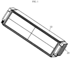
- a battery module of the related art is manufactured in a structure in which a cell assembly 20 is surrounded by a frame 10 formed in one piece by an extrusion or die casting method as shown in FIG. 1 .
- Korean Patent Application Publication No. 2015-0031861 discloses a battery module in which a side plate is placed adjacent to a side of a cell assembly.
- the battery module disclosed in Korean Patent Application Publication No. 2015-0031861 includes: a plurality of battery cells aligned in one direction; and a side plate placed adjacent to sides of the battery cells, wherein the side plate includes a pressing region protruding toward the battery cells to press the battery cells, and since the pressing region applies tension to the battery cells and prevents movement of the battery cells, the battery module is improved in safety.
- Korean Patent Application Publication No. 2012-0051237 discloses a battery module case in which at least two pouch-type secondary batteries are stacked and arranged side by side with electrode tap sides of the pouch-type secondary batteries being arranged in the same manner, wherein each of the pouch-type secondary batteries is mounted in a vertically or horizontally sliding manner, the battery module case is coupled to outer surfaces of the pouch-type secondary batteries including the electrode tap sides, and the battery module case has an upper, lower, and side separable assembly structure.
- the present disclosure is designed by taking problems as described above into consideration, and therefore the present disclosure is directed to providing a battery module having a structure in which a frame is formed by assembling plates made of a material such as a metal sheet, and to providing a frame assembly therefor.
- Another object of the present disclosure is to provide a battery module having a structure in which a frame is formed through a welding process, and to provide a frame assembly therefor.
- a battery module including: a plurality of cells; and a fame assembly including a lower plate configured to support a lower end surfaces of the plurality of cells, a side plate extending perpendicularly from any opposite edge ends of the lower plate and placed adjacent to an outermost side of the cells, and an upper plate coupled to an upper end of the side plate to cover an upper portion of the cells.
- Opposite edge portions of the upper plate are coupled to the upper ends of the side plate by welding.
- the battery module of the present disclosure further includes first guide plates extending perpendicularly from other opposite edge ends of the lower plate to prevent separation of the cells.
- the first guide plates are bent from the lower plate in one piece with the lower plate.
- the battery module of the present disclosure may further include a second guide plate extending perpendicularly from an edge end of the upper plate to prevent separation of the cells.
- the second guide plate may be bent from the upper plate in one piece with the upper plate.
- the side plate may be bent from the lower plate in one piece with the lower plate.
- a frame assembly of a battery module for supporting at least one cell from an outside of the battery module, the frame assembly including: a lower plate configured to support a lower end surface of the cell; a side plate perpendicularly extending from any opposite edge ends of the lower plate and placed adjacent to an outermost side of the cell; and an upper plate placed to cover an upper portion of the cell, opposite edge ends of the upper plate being coupled to an upper end of the side plate.
- the frame assembly of the battery module is made of a plate material such as a metal sheet for weight reduction and is assembled through a welding process for reducing process costs.
- the expansion of the side plate may be properly allowed, and thus the lifespan of the cell may not be negatively affected.
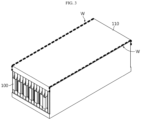
- FIG. 2 is an exploded perspective view illustrating a configuration of a battery module according to the invention.
- the battery module includes: a plurality of cells 100; and a frame assembly 110 arranged to surround the plurality of cells 100 and including a lower plate 111, a side plate 113, and an upper plate 114.
- Each of the cells 100 has a thin plate-like body, and is preferably a pouch-type secondary cell.
- the plurality of cells 100 are arranged in one direction to substantially form a stacked structure.
- the frame assembly 110 is a structure for accommodating, supporting, and protecting the cells 100 in units of a plurality of cells, and the frame assembly 110 includes the lower plate 111 placed below the cells 100, the side plate 113 placed adjacent to outermost sides of the cells 100, and the upper plate 114 placed above the cells 100.
- Each of the plates 111, 113, and 114 of the frame assembly 110 is formed of a metal sheet (or a metal plate) such as an aluminum plate having a thin thickness of about several millimeters.
- the lower plate 111 has a base surface capable of collectively supporting lower end surfaces of the plurality of cells 100.
- the side plate 113 extends perpendicularly upwards from any opposite edge ends of the lower plate 111 and are placed adjacent to the outermost sides of the cells 100. That is, a pair of side plates 113 are provided, and the interval between the side plates 113 is set to such an extent as to accommodate the plurality of cells 100.
- the side plates 113 are bent from the lower plate 111 in one piece with the lower plate 111 to form a ⁇ -shaped section.
- a first guide plate 112 extends perpendicularly upwards from other opposite edge ends of the lower plate 111 to a height of several centimeters so as to prevent separation of the cells 100 from the frame assembly 110 in forward and backward directions, that is, in directions perpendicular to the direction in which the cells 100 are arranged.
- the first guide plate 112 is bent from the lower plate 111 in one piece with the lower plate 111.
- the upper plate 114 is coupled to upper ends of the side plates 113 to collectively cover upper portions of the plurality of cells 100.
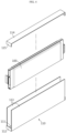
- opposite edge portions of the upper plate 114 are respectively welded to the upper ends of the side plates 113.
- weld zones (refer to W in FIG. 3 ) are formed on edge portions at which the side plates 113 meet the upper plate 114.
- a welding method such as a laser welding method, an ultrasonic welding method, or a spot welding method may be used.
- FIG. 3 illustrates a state in which the upper plate 114 is assembled to the upper ends of the side plates 113 by welding.
- the battery module including the frame assembly 110 provided in units of a plurality of cells 100 is manufactured by welding edge portions of the upper plate 114 to the upper ends of the side plates 113 in a state in which the plurality of cells 100 are arranged in the frame assembly 110.
- the width of the upper plate 114 is substantially the same as the interval between inner surfaces of the pair of side plates 113 or the interval between outer surfaces of the pair of side plates 113.
- a second guide plate 115 extends to a height of several centimeters, perpendicularly downwards from opposite edge ends of the upper plate 114 which are not in contact with the side plates 113, so as to prevent separation of the cells 100 from the frame assembly 110 in forward and backward directions, that is, in directions perpendicular to the direction in which the cells 100 are arranged.
- the second guide plate 115 is bent from the upper plate 114 in one piece with the upper plate 114.
- the battery module includes: a cell 100 disposed alone; and the frame assembly 110 provided to correspond to the single cell 100 and disposed to surround the cell 100, the frame assembly 110 including a lower plate 111, a side plate 113, and an upper plate 114.
- the frame assembly 110 is provided to correspond to each single cell 100, only one cell 100 is accommodated in the frame assembly 110, and thus the frame assembly 110 may have a slim shape.
- the lower plate 111, the side plate 113, and the upper plate 114 of the frame assembly 110 have the same specific configuration and coupling relationship as those described in the above embodiment, and thus detailed descriptions thereof will be omitted.
- the battery module including the frame assembly 110 provided on a cell basis is manufactured by welding an edge portion of the upper plate 114 to an upper end of the side plate 113 in a state in which the single cell 100 is placed in the frame assembly 110.
- weld zones W are formed on edge portions at which the side plate 113 meets the upper plate 114.
- the frame assembly 110 is assembled in units of a single cell 100 or a plurality of cells 100.
- the frame assembly 110 may be light because the lower plate 111, the side plate 113, and the upper plate 114 formed of a metal sheet (or a metal plate) such as an aluminum plate are organically coupled to each other.
- the lower plate 111 and the side plate 113 are formed in one piece through a bending process, and the upper plate 114 is coupled to the upper end of the side plate 113 by a welding process such as a laser welding process or an ultrasonic welding process.
- a battery module having a lower weight and incurring lower assembly costs compared to the case of using a frame manufactured by a convention extrusion or die casting method may be provided.
Landscapes
- Chemical & Material Sciences (AREA)
- Chemical Kinetics & Catalysis (AREA)
- Electrochemistry (AREA)
- General Chemical & Material Sciences (AREA)
- Engineering & Computer Science (AREA)
- Manufacturing & Machinery (AREA)
- Inorganic Chemistry (AREA)
- Battery Mounting, Suspending (AREA)
- Sealing Battery Cases Or Jackets (AREA)
Claims (4)
- Batteriemodul umfassend:eine Mehrzahl von Zellen (100); undeine Rahmenanordnung (110), welche eine untere Platte (111), welche dazu eingerichtet ist, untere Endflächen der Mehrzahl von Zellen (100) zu stützen, ein Paar von Seitenplatten (113), welche sich senkrecht von entgegengesetzten Randenden der unteren Platte (111) erstrecken und angrenzend zu einer äußersten Seite der Zellen (100) angeordnet sind, und eine obere Platte (114) umfasst, welche mit den oberen Enden der Seitenplatten (113) gekoppelt ist, um einen oberen Abschnitt der Zellen (100) zu bedecken,wobei entgegengesetzte Randabschnitte der obere Platte (114) jeweils an den oberen Enden der Seitenplatten (113) angeschweißt sind,wobei das Batteriemodul ferner erste Führungsplatten (112) umfasst, welche sich senkrecht von anderen entgegengesetzten Randenden der unteren Platte (111) erstrecken, um eine Separation der Mehrzahl von Zellen (100) zu verhindern,
unddadurch gekennzeichnet, dass die ersten Führungsplatten (112) von der unteren Platte (111) in einem Stück mit der unteren Platte (111) gebogen sind. - Batteriemodul nach Anspruch 1, ferner umfassend eine zweite Führungsplatte (115), welche sich senkrecht von einem Randende der oberen Platte (114) erstreckt, um eine Separation der Mehrzahl von Zellen (100) zu verhindern.
- Batteriemodul nach Anspruch 2, wobei die zweite Führungsplatte (115) von der oberen Platte (114) in einem Stück mit der oberen Platte (114) gebogen ist.
- Batteriemodul nach Anspruch 1, wobei die Seitenplatten (113) von der unteren Platte (111) in einem Stück mit der unteren Platte (111) gebogen sind.
Applications Claiming Priority (2)
| Application Number | Priority Date | Filing Date | Title |
|---|---|---|---|
| KR1020160103079A KR102065098B1 (ko) | 2016-08-12 | 2016-08-12 | 프레임의 구조가 개선된 배터리 모듈 및 이를 위한 프레임 어셈블리 |
| PCT/KR2017/008759 WO2018030846A1 (ko) | 2016-08-12 | 2017-08-11 | 프레임의 구조가 개선된 배터리 모듈 및 이를 위한 프레임 어셈블리 |
Publications (3)
| Publication Number | Publication Date |
|---|---|
| EP3389112A1 EP3389112A1 (de) | 2018-10-17 |
| EP3389112A4 EP3389112A4 (de) | 2018-12-12 |
| EP3389112B1 true EP3389112B1 (de) | 2025-06-25 |
Family
ID=61163180
Family Applications (1)
| Application Number | Title | Priority Date | Filing Date |
|---|---|---|---|
| EP17839863.2A Active EP3389112B1 (de) | 2016-08-12 | 2017-08-11 | Batteriemodul mit verbesserter rahmenstruktur |
Country Status (9)
| Country | Link |
|---|---|
| US (1) | US10985421B2 (de) |
| EP (1) | EP3389112B1 (de) |
| JP (1) | JP6791982B2 (de) |
| KR (1) | KR102065098B1 (de) |
| CN (1) | CN108475745B (de) |
| DE (3) | DE202017007747U1 (de) |
| ES (1) | ES3037503T3 (de) |
| HU (1) | HUE072273T2 (de) |
| WO (1) | WO2018030846A1 (de) |
Families Citing this family (27)
| Publication number | Priority date | Publication date | Assignee | Title |
|---|---|---|---|---|
| KR102267606B1 (ko) * | 2017-11-30 | 2021-06-21 | 주식회사 엘지에너지솔루션 | 셀 조립체에 대한 초기 가압력 강화 구조를 갖는 배터리 모듈 및 그 제조방법 |
| KR102328729B1 (ko) | 2018-05-03 | 2021-11-17 | 주식회사 엘지에너지솔루션 | 배터리 모듈 및 이를 포함하는 배터리 팩 |
| KR102726473B1 (ko) * | 2018-12-20 | 2024-11-06 | 주식회사 엘지에너지솔루션 | 두께 편차가 있는 전지팩 하우징 및 이를 포함하는 전지팩 |
| CN210092151U (zh) * | 2019-03-28 | 2020-02-18 | 泰科电子日本合同会社 | 用于电池模组的连接组件及电池模组 |
| KR102187278B1 (ko) | 2019-04-22 | 2020-12-04 | (주)휴민텍 | 프레임 삽입장치 |
| KR102212849B1 (ko) | 2019-04-22 | 2021-02-05 | (주)휴민텍 | 프레임 용접기용 지그장치 |
| EP3923370A4 (de) * | 2019-06-12 | 2022-04-20 | LG Energy Solution, Ltd. | Batteriemodul, herstellungsverfahren dafür und batteriesatz |
| KR102465865B1 (ko) * | 2019-06-12 | 2022-11-10 | 주식회사 엘지에너지솔루션 | 전지 모듈, 이의 제조 방법 및 전지팩 |
| KR102391985B1 (ko) | 2019-06-14 | 2022-04-27 | 주식회사 엘지에너지솔루션 | 전지 모듈 및 그 제조 방법 |
| KR102472690B1 (ko) | 2019-07-19 | 2022-11-29 | 주식회사 엘지에너지솔루션 | 전지 모듈 및 이를 포함하는 전지팩 |
| WO2021015461A1 (ko) | 2019-07-19 | 2021-01-28 | 주식회사 엘지화학 | 전지 모듈 및 이를 포함하는 전지 팩 |
| JP6898972B2 (ja) * | 2019-08-07 | 2021-07-07 | 本田技研工業株式会社 | バッテリケースの製造方法及びバッテリケース |
| KR102398574B1 (ko) * | 2019-10-10 | 2022-05-13 | 주식회사 엘지에너지솔루션 | 전지 모듈 및 이를 포함하는 전지 팩 |
| KR102480736B1 (ko) | 2019-10-25 | 2022-12-22 | 주식회사 엘지에너지솔루션 | 전지 모듈 및 이를 포함하는 전지 팩 |
| KR102792212B1 (ko) * | 2020-02-10 | 2025-04-04 | 주식회사 엘지에너지솔루션 | 전지 모듈 및 그 제조 방법 |
| CN114270613A (zh) * | 2020-03-06 | 2022-04-01 | 株式会社Lg新能源 | 电池模块及其制造方法 |
| US12597660B2 (en) | 2020-04-10 | 2026-04-07 | Lg Energy Solution, Ltd. | Battery module and method of manufacturing the same |
| KR20220017741A (ko) * | 2020-08-05 | 2022-02-14 | 주식회사 엘지에너지솔루션 | 셀 스웰링을 흡수할 수 있는 구조를 갖는 배터리 모듈, 그리고 이를 포함하는 배터리 팩 및 자동차 |
| KR102929045B1 (ko) | 2020-08-07 | 2026-02-19 | 주식회사 엘지에너지솔루션 | 전지 모듈 및 이를 포함하는 전지 팩 |
| KR102945051B1 (ko) | 2020-09-22 | 2026-03-26 | 주식회사 엘지에너지솔루션 | 전지 모듈 및 이를 포함하는 전지팩 |
| KR102937927B1 (ko) | 2020-09-22 | 2026-03-10 | 주식회사 엘지에너지솔루션 | 전지 모듈 및 이를 포함하는 전지팩 |
| KR20220051709A (ko) | 2020-10-19 | 2022-04-26 | 주식회사 엘지에너지솔루션 | 전지 모듈 및 이를 포함하는 전지팩 |
| KR102825807B1 (ko) * | 2021-01-15 | 2025-06-25 | 주식회사 엘지에너지솔루션 | 화재 발생 및 폭발을 방지할 수 있는 구조를 갖는 배터리 모듈, 그리고 이를 포함하는 배터리 팩 및 ess |
| KR102298326B1 (ko) * | 2021-05-07 | 2021-09-03 | 구승조 | 배터리용 커버 및 이의 제조방법 |
| US20230043355A1 (en) * | 2021-08-04 | 2023-02-09 | Lg Energy Solution, Ltd. | Battery pack and vehicle including the same |
| CN114050301B (zh) * | 2021-11-11 | 2024-03-12 | 合肥国轩高科动力能源有限公司 | 一种锂电池模组外框装配装置 |
| KR20240114481A (ko) * | 2023-01-17 | 2024-07-24 | 에스케이온 주식회사 | 배터리 셀 어셈블리 및 이를 포함하는 배터리 팩 |
Citations (1)
| Publication number | Priority date | Publication date | Assignee | Title |
|---|---|---|---|---|
| EP3363057B1 (de) * | 2015-10-16 | 2019-08-07 | Robert Bosch GmbH | Beutel mit tiefem format für batteriezelle |
Family Cites Families (33)
| Publication number | Priority date | Publication date | Assignee | Title |
|---|---|---|---|---|
| JPS5141663U (de) | 1974-09-24 | 1976-03-27 | ||
| JPS57197877U (de) | 1981-06-09 | 1982-12-15 | ||
| JPS57197677U (de) * | 1981-06-09 | 1982-12-15 | ||
| CN1180506C (zh) | 1999-03-26 | 2004-12-15 | 松下电器产业株式会社 | 叠合片封装型电池 |
| CN2484650Y (zh) | 2001-07-26 | 2002-04-03 | 杨渊洲 | 模块化电池组结构 |
| KR100601577B1 (ko) | 2005-03-24 | 2006-07-19 | 삼성에스디아이 주식회사 | 이차 전지 |
| KR100686814B1 (ko) | 2005-04-26 | 2007-02-26 | 삼성에스디아이 주식회사 | 폴리머 배터리 팩 및 그 제조 방법 |
| US8100271B2 (en) | 2006-02-02 | 2012-01-24 | C & C Power | Tiered battery cabinet |
| CN101304080A (zh) | 2008-03-14 | 2008-11-12 | 上汽通用五菱汽车股份有限公司 | 电瓶支架装置 |
| JP2011151006A (ja) * | 2009-12-25 | 2011-08-04 | Sanyo Electric Co Ltd | バッテリシステムおよびそれを備えた電動車両 |
| KR101146363B1 (ko) * | 2010-06-04 | 2012-05-17 | 에스비리모티브 주식회사 | 배터리 팩 |
| US20120052341A1 (en) * | 2010-09-01 | 2012-03-01 | Duk-Jung Kim | Rechargeable battery |
| KR101441423B1 (ko) | 2010-09-01 | 2014-10-20 | 에스케이이노베이션 주식회사 | 일체형 전지 연결 장치가 구비되는 고전압 배터리 |
| KR101680709B1 (ko) | 2010-11-12 | 2016-12-12 | 에스케이이노베이션 주식회사 | 배터리 모듈 케이스 |
| CN103283063B (zh) | 2010-12-28 | 2016-02-24 | 株式会社Lg化学 | 电池模块接收装置、电池模块恒温器以及包括其的蓄电系统 |
| CN103283083A (zh) | 2011-03-16 | 2013-09-04 | 松下电器产业株式会社 | 锂二次电池的充放电方法和充放电系统 |
| CN102315396B (zh) | 2011-08-08 | 2014-12-03 | 佛山市顺德区精进能源有限公司 | 一种锂离子电池模块结构 |
| KR101292984B1 (ko) | 2011-08-22 | 2013-08-02 | 로베르트 보쉬 게엠베하 | 배터리 모듈 |
| KR101883915B1 (ko) * | 2011-09-30 | 2018-08-02 | 삼성에스디아이 주식회사 | 지지부재를 포함하는 배터리 모듈 |
| KR101658027B1 (ko) * | 2011-11-22 | 2016-09-21 | 삼성에스디아이 주식회사 | 배터리 팩 |
| JP5552109B2 (ja) | 2011-12-27 | 2014-07-16 | 株式会社神戸製鋼所 | 車載用バッテリートレイおよび車載用バッテリーフレーム |
| US20130171487A1 (en) * | 2011-12-30 | 2013-07-04 | Roger Bull | Rechargeable battery and method |
| JP5591280B2 (ja) | 2012-04-13 | 2014-09-17 | トヨタ自動車株式会社 | 電池、組電池 |
| JP5796785B2 (ja) * | 2012-09-28 | 2015-10-21 | 株式会社Gsユアサ | 蓄電装置 |
| KR101669118B1 (ko) | 2013-01-03 | 2016-10-25 | 삼성에스디아이 주식회사 | 배터리 팩 |
| US20140295235A1 (en) * | 2013-03-29 | 2014-10-02 | Samsung Sdi Co., Ltd. | Battery module |
| CN203398193U (zh) | 2013-09-10 | 2014-01-15 | 日照华轩新能源有限公司 | 一种电动钓鱼船用锂电池组 |
| KR20150031861A (ko) | 2013-09-17 | 2015-03-25 | 삼성에스디아이 주식회사 | 배터리 모듈 |
| CN203557070U (zh) * | 2013-10-31 | 2014-04-23 | 中国科学院西安光学精密机械研究所 | 电池焊接用激光焊接夹具 |
| KR101546002B1 (ko) * | 2013-11-27 | 2015-08-21 | 코칩 주식회사 | 전기화학 에너지 저장 장치 |
| JP6194300B2 (ja) * | 2014-11-07 | 2017-09-06 | 本田技研工業株式会社 | 蓄電装置 |
| CN204441373U (zh) * | 2015-02-04 | 2015-07-01 | 合肥国轩高科动力能源股份公司 | 一种电池组成组结构 |
| JP6020974B2 (ja) | 2015-08-21 | 2016-11-02 | 株式会社Gsユアサ | 蓄電装置 |
-
2016
- 2016-08-12 KR KR1020160103079A patent/KR102065098B1/ko active Active
-
2017
- 2017-08-11 DE DE202017007747.7U patent/DE202017007747U1/de active Active
- 2017-08-11 HU HUE17839863A patent/HUE072273T2/hu unknown
- 2017-08-11 WO PCT/KR2017/008759 patent/WO2018030846A1/ko not_active Ceased
- 2017-08-11 US US16/064,183 patent/US10985421B2/en active Active
- 2017-08-11 DE DE202017007749.3U patent/DE202017007749U1/de active Active
- 2017-08-11 EP EP17839863.2A patent/EP3389112B1/de active Active
- 2017-08-11 JP JP2018556778A patent/JP6791982B2/ja active Active
- 2017-08-11 CN CN201780005702.0A patent/CN108475745B/zh active Active
- 2017-08-11 DE DE202017007736.1U patent/DE202017007736U1/de active Active
- 2017-08-11 ES ES17839863T patent/ES3037503T3/es active Active
Patent Citations (1)
| Publication number | Priority date | Publication date | Assignee | Title |
|---|---|---|---|---|
| EP3363057B1 (de) * | 2015-10-16 | 2019-08-07 | Robert Bosch GmbH | Beutel mit tiefem format für batteriezelle |
Also Published As
| Publication number | Publication date |
|---|---|
| KR20180018109A (ko) | 2018-02-21 |
| JP2019502250A (ja) | 2019-01-24 |
| US20190006647A1 (en) | 2019-01-03 |
| DE202017007749U1 (de) | 2025-12-01 |
| JP6791982B2 (ja) | 2020-11-25 |
| HUE072273T2 (hu) | 2025-11-28 |
| KR102065098B1 (ko) | 2020-01-10 |
| WO2018030846A1 (ko) | 2018-02-15 |
| US10985421B2 (en) | 2021-04-20 |
| ES3037503T3 (en) | 2025-10-02 |
| DE202017007736U1 (de) | 2025-09-01 |
| CN108475745B (zh) | 2022-07-26 |
| EP3389112A4 (de) | 2018-12-12 |
| CN108475745A (zh) | 2018-08-31 |
| DE202017007747U1 (de) | 2025-12-01 |
| EP3389112A1 (de) | 2018-10-17 |
Similar Documents
| Publication | Publication Date | Title |
|---|---|---|
| EP3389112B1 (de) | Batteriemodul mit verbesserter rahmenstruktur | |
| EP3389111B1 (de) | Batteriemodul mit bandartigem rahmen und rahmenanordnung dafür | |
| KR102271377B1 (ko) | 배터리 모듈 | |
| EP2819210B1 (de) | Batteriemodul | |
| EP3352244B1 (de) | Batteriemodul mit endplatten mit verbesserter struktur und endplattenelement dafür | |
| US11594790B2 (en) | Method of manufacturing battery pack and battery pack | |
| EP2515360B1 (de) | Batteriemodul | |
| KR102211369B1 (ko) | 배터리 모듈 | |
| US11171355B2 (en) | Binding member, and battery module | |
| EP3579299B1 (de) | Batteriemodul | |
| US9379366B2 (en) | Battery module | |
| US11322805B2 (en) | Method of manufacturing battery pack and battery pack | |
| JP2019186041A (ja) | 組電池及び組電池の製造方法 | |
| KR20250009947A (ko) | 전지 모듈 및 그 제조 방법 | |
| EP3511994B1 (de) | Batterieabdeckung, sekundärbatterie und batteriemodul | |
| EP2940756B1 (de) | Batteriemodul | |
| JP6782830B2 (ja) | 電池モジュール | |
| US20200321570A1 (en) | Battery Pack | |
| US10608228B2 (en) | Busbar module and busbar | |
| US20260001165A1 (en) | Battery module and method for assembling the same | |
| CN118661324A (zh) | 电池组 |
Legal Events
| Date | Code | Title | Description |
|---|---|---|---|
| STAA | Information on the status of an ep patent application or granted ep patent |
Free format text: STATUS: THE INTERNATIONAL PUBLICATION HAS BEEN MADE |
|
| PUAI | Public reference made under article 153(3) epc to a published international application that has entered the european phase |
Free format text: ORIGINAL CODE: 0009012 |
|
| STAA | Information on the status of an ep patent application or granted ep patent |
Free format text: STATUS: REQUEST FOR EXAMINATION WAS MADE |
|
| 17P | Request for examination filed |
Effective date: 20180712 |
|
| AK | Designated contracting states |
Kind code of ref document: A1 Designated state(s): AL AT BE BG CH CY CZ DE DK EE ES FI FR GB GR HR HU IE IS IT LI LT LU LV MC MK MT NL NO PL PT RO RS SE SI SK SM TR |
|
| AX | Request for extension of the european patent |
Extension state: BA ME |
|
| A4 | Supplementary search report drawn up and despatched |
Effective date: 20181113 |
|
| RIC1 | Information provided on ipc code assigned before grant |
Ipc: H01M 10/04 20060101ALI20181105BHEP Ipc: H01M 2/34 20060101ALI20181105BHEP Ipc: H01M 2/10 20060101AFI20181105BHEP |
|
| DAV | Request for validation of the european patent (deleted) | ||
| DAX | Request for extension of the european patent (deleted) | ||
| RAP1 | Party data changed (applicant data changed or rights of an application transferred) |
Owner name: LG ENERGY SOLUTION LTD. |
|
| RAP3 | Party data changed (applicant data changed or rights of an application transferred) |
Owner name: LG ENERGY SOLUTION, LTD. |
|
| STAA | Information on the status of an ep patent application or granted ep patent |
Free format text: STATUS: EXAMINATION IS IN PROGRESS |
|
| 17Q | First examination report despatched |
Effective date: 20240625 |
|
| REG | Reference to a national code |
Ref legal event code: R079 Free format text: PREVIOUS MAIN CLASS: H01M0002100000 Ref country code: DE Ref document number: 602017090171 Country of ref document: DE Ipc: H01M0050105000 |
|
| GRAP | Despatch of communication of intention to grant a patent |
Free format text: ORIGINAL CODE: EPIDOSNIGR1 |
|
| STAA | Information on the status of an ep patent application or granted ep patent |
Free format text: STATUS: GRANT OF PATENT IS INTENDED |
|
| RIC1 | Information provided on ipc code assigned before grant |
Ipc: H01M 50/264 20210101ALI20250225BHEP Ipc: H01M 50/224 20210101ALI20250225BHEP Ipc: H01M 50/211 20210101ALI20250225BHEP Ipc: H01M 50/202 20210101ALI20250225BHEP Ipc: H01M 50/105 20210101AFI20250225BHEP |
|
| INTG | Intention to grant announced |
Effective date: 20250317 |
|
| P01 | Opt-out of the competence of the unified patent court (upc) registered |
Free format text: CASE NUMBER: APP_16817/2025 Effective date: 20250407 |
|
| GRAS | Grant fee paid |
Free format text: ORIGINAL CODE: EPIDOSNIGR3 |
|
| GRAA | (expected) grant |
Free format text: ORIGINAL CODE: 0009210 |
|
| STAA | Information on the status of an ep patent application or granted ep patent |
Free format text: STATUS: THE PATENT HAS BEEN GRANTED |
|
| AK | Designated contracting states |
Kind code of ref document: B1 Designated state(s): AL AT BE BG CH CY CZ DE DK EE ES FI FR GB GR HR HU IE IS IT LI LT LU LV MC MK MT NL NO PL PT RO RS SE SI SK SM TR |
|
| REG | Reference to a national code |
Ref country code: GB Ref legal event code: FG4D |
|
| REG | Reference to a national code |
Ref country code: CH Ref legal event code: EP |
|
| REG | Reference to a national code |
Ref country code: DE Ref legal event code: R096 Ref document number: 602017090171 Country of ref document: DE |
|
| REG | Reference to a national code |
Ref country code: CH Ref legal event code: EP |
|
| REG | Reference to a national code |
Ref country code: IE Ref legal event code: FG4D |
|
| REG | Reference to a national code |
Ref country code: ES Ref legal event code: FG2A Ref document number: 3037503 Country of ref document: ES Kind code of ref document: T3 Effective date: 20251002 |
|
| PG25 | Lapsed in a contracting state [announced via postgrant information from national office to epo] |
Ref country code: FI Free format text: LAPSE BECAUSE OF FAILURE TO SUBMIT A TRANSLATION OF THE DESCRIPTION OR TO PAY THE FEE WITHIN THE PRESCRIBED TIME-LIMIT Effective date: 20250625 |
|
| PGFP | Annual fee paid to national office [announced via postgrant information from national office to epo] |
Ref country code: ES Payment date: 20250911 Year of fee payment: 9 |
|
| PGFP | Annual fee paid to national office [announced via postgrant information from national office to epo] |
Ref country code: DE Payment date: 20250721 Year of fee payment: 9 |
|
| REG | Reference to a national code |
Ref country code: LT Ref legal event code: MG9D |
|
| PG25 | Lapsed in a contracting state [announced via postgrant information from national office to epo] |
Ref country code: GR Free format text: LAPSE BECAUSE OF FAILURE TO SUBMIT A TRANSLATION OF THE DESCRIPTION OR TO PAY THE FEE WITHIN THE PRESCRIBED TIME-LIMIT Effective date: 20250926 Ref country code: NO Free format text: LAPSE BECAUSE OF FAILURE TO SUBMIT A TRANSLATION OF THE DESCRIPTION OR TO PAY THE FEE WITHIN THE PRESCRIBED TIME-LIMIT Effective date: 20250925 |
|
| PG25 | Lapsed in a contracting state [announced via postgrant information from national office to epo] |
Ref country code: BG Free format text: LAPSE BECAUSE OF FAILURE TO SUBMIT A TRANSLATION OF THE DESCRIPTION OR TO PAY THE FEE WITHIN THE PRESCRIBED TIME-LIMIT Effective date: 20250625 |
|
| PGFP | Annual fee paid to national office [announced via postgrant information from national office to epo] |
Ref country code: HU Payment date: 20250929 Year of fee payment: 9 Ref country code: GB Payment date: 20250722 Year of fee payment: 9 Ref country code: BE Payment date: 20250722 Year of fee payment: 9 |
|
| PG25 | Lapsed in a contracting state [announced via postgrant information from national office to epo] |
Ref country code: HR Free format text: LAPSE BECAUSE OF FAILURE TO SUBMIT A TRANSLATION OF THE DESCRIPTION OR TO PAY THE FEE WITHIN THE PRESCRIBED TIME-LIMIT Effective date: 20250625 |
|
| PGFP | Annual fee paid to national office [announced via postgrant information from national office to epo] |
Ref country code: FR Payment date: 20250725 Year of fee payment: 9 |
|
| PG25 | Lapsed in a contracting state [announced via postgrant information from national office to epo] |
Ref country code: RS Free format text: LAPSE BECAUSE OF FAILURE TO SUBMIT A TRANSLATION OF THE DESCRIPTION OR TO PAY THE FEE WITHIN THE PRESCRIBED TIME-LIMIT Effective date: 20250925 |
|
| PG25 | Lapsed in a contracting state [announced via postgrant information from national office to epo] |
Ref country code: LV Free format text: LAPSE BECAUSE OF FAILURE TO SUBMIT A TRANSLATION OF THE DESCRIPTION OR TO PAY THE FEE WITHIN THE PRESCRIBED TIME-LIMIT Effective date: 20250625 |
|
| REG | Reference to a national code |
Ref country code: NL Ref legal event code: MP Effective date: 20250625 |
|
| PG25 | Lapsed in a contracting state [announced via postgrant information from national office to epo] |
Ref country code: NL Free format text: LAPSE BECAUSE OF FAILURE TO SUBMIT A TRANSLATION OF THE DESCRIPTION OR TO PAY THE FEE WITHIN THE PRESCRIBED TIME-LIMIT Effective date: 20250625 |
|
| REG | Reference to a national code |
Ref country code: HU Ref legal event code: AG4A Ref document number: E072273 Country of ref document: HU |
|
| PG25 | Lapsed in a contracting state [announced via postgrant information from national office to epo] |
Ref country code: PT Free format text: LAPSE BECAUSE OF FAILURE TO SUBMIT A TRANSLATION OF THE DESCRIPTION OR TO PAY THE FEE WITHIN THE PRESCRIBED TIME-LIMIT Effective date: 20251027 |
|
| REG | Reference to a national code |
Ref country code: AT Ref legal event code: MK05 Ref document number: 1807556 Country of ref document: AT Kind code of ref document: T Effective date: 20250625 |
|
| PG25 | Lapsed in a contracting state [announced via postgrant information from national office to epo] |
Ref country code: IS Free format text: LAPSE BECAUSE OF FAILURE TO SUBMIT A TRANSLATION OF THE DESCRIPTION OR TO PAY THE FEE WITHIN THE PRESCRIBED TIME-LIMIT Effective date: 20251025 |
|
| PG25 | Lapsed in a contracting state [announced via postgrant information from national office to epo] |
Ref country code: AT Free format text: LAPSE BECAUSE OF FAILURE TO SUBMIT A TRANSLATION OF THE DESCRIPTION OR TO PAY THE FEE WITHIN THE PRESCRIBED TIME-LIMIT Effective date: 20250625 Ref country code: SM Free format text: LAPSE BECAUSE OF FAILURE TO SUBMIT A TRANSLATION OF THE DESCRIPTION OR TO PAY THE FEE WITHIN THE PRESCRIBED TIME-LIMIT Effective date: 20250625 |
|
| PG25 | Lapsed in a contracting state [announced via postgrant information from national office to epo] |
Ref country code: CZ Free format text: LAPSE BECAUSE OF FAILURE TO SUBMIT A TRANSLATION OF THE DESCRIPTION OR TO PAY THE FEE WITHIN THE PRESCRIBED TIME-LIMIT Effective date: 20250625 |
|
| PG25 | Lapsed in a contracting state [announced via postgrant information from national office to epo] |
Ref country code: PL Free format text: LAPSE BECAUSE OF FAILURE TO SUBMIT A TRANSLATION OF THE DESCRIPTION OR TO PAY THE FEE WITHIN THE PRESCRIBED TIME-LIMIT Effective date: 20250625 |
|
| PG25 | Lapsed in a contracting state [announced via postgrant information from national office to epo] |
Ref country code: EE Free format text: LAPSE BECAUSE OF FAILURE TO SUBMIT A TRANSLATION OF THE DESCRIPTION OR TO PAY THE FEE WITHIN THE PRESCRIBED TIME-LIMIT Effective date: 20250625 |
|
| PG25 | Lapsed in a contracting state [announced via postgrant information from national office to epo] |
Ref country code: SK Free format text: LAPSE BECAUSE OF FAILURE TO SUBMIT A TRANSLATION OF THE DESCRIPTION OR TO PAY THE FEE WITHIN THE PRESCRIBED TIME-LIMIT Effective date: 20250625 |
|
| PG25 | Lapsed in a contracting state [announced via postgrant information from national office to epo] |
Ref country code: RO Free format text: LAPSE BECAUSE OF FAILURE TO SUBMIT A TRANSLATION OF THE DESCRIPTION OR TO PAY THE FEE WITHIN THE PRESCRIBED TIME-LIMIT Effective date: 20250625 |
|
| REG | Reference to a national code |
Ref country code: CH Ref legal event code: H13 Free format text: ST27 STATUS EVENT CODE: U-0-0-H10-H13 (AS PROVIDED BY THE NATIONAL OFFICE) Effective date: 20260324 |
|
| PG25 | Lapsed in a contracting state [announced via postgrant information from national office to epo] |
Ref country code: MC Free format text: LAPSE BECAUSE OF FAILURE TO SUBMIT A TRANSLATION OF THE DESCRIPTION OR TO PAY THE FEE WITHIN THE PRESCRIBED TIME-LIMIT Effective date: 20250625 |
|
| PG25 | Lapsed in a contracting state [announced via postgrant information from national office to epo] |
Ref country code: DK Free format text: LAPSE BECAUSE OF FAILURE TO SUBMIT A TRANSLATION OF THE DESCRIPTION OR TO PAY THE FEE WITHIN THE PRESCRIBED TIME-LIMIT Effective date: 20250625 |
|
| PG25 | Lapsed in a contracting state [announced via postgrant information from national office to epo] |
Ref country code: LU Free format text: LAPSE BECAUSE OF NON-PAYMENT OF DUE FEES Effective date: 20250811 Ref country code: IT Free format text: LAPSE BECAUSE OF FAILURE TO SUBMIT A TRANSLATION OF THE DESCRIPTION OR TO PAY THE FEE WITHIN THE PRESCRIBED TIME-LIMIT Effective date: 20250625 |
|
| PG25 | Lapsed in a contracting state [announced via postgrant information from national office to epo] |
Ref country code: CH Free format text: LAPSE BECAUSE OF NON-PAYMENT OF DUE FEES Effective date: 20250831 |
|
| PLBE | No opposition filed within time limit |
Free format text: ORIGINAL CODE: 0009261 |
|
| STAA | Information on the status of an ep patent application or granted ep patent |
Free format text: STATUS: NO OPPOSITION FILED WITHIN TIME LIMIT |