EP3388802B1 - Schaltung und verfahren zur temperaturmessung und temperaturfühler - Google Patents
Schaltung und verfahren zur temperaturmessung und temperaturfühler Download PDFInfo
- Publication number
- EP3388802B1 EP3388802B1 EP18162780.3A EP18162780A EP3388802B1 EP 3388802 B1 EP3388802 B1 EP 3388802B1 EP 18162780 A EP18162780 A EP 18162780A EP 3388802 B1 EP3388802 B1 EP 3388802B1
- Authority
- EP
- European Patent Office
- Prior art keywords
- temperature
- sensor
- type
- semiconductor device
- resistor
- Prior art date
- Legal status (The legal status is an assumption and is not a legal conclusion. Google has not performed a legal analysis and makes no representation as to the accuracy of the status listed.)
- Active
Links
Images



Classifications
-
- G—PHYSICS
- G01—MEASURING; TESTING
- G01K—MEASURING TEMPERATURE; MEASURING QUANTITY OF HEAT; THERMALLY-SENSITIVE ELEMENTS NOT OTHERWISE PROVIDED FOR
- G01K1/00—Details of thermometers not specially adapted for particular types of thermometer
- G01K1/02—Means for indicating or recording specially adapted for thermometers
- G01K1/026—Means for indicating or recording specially adapted for thermometers arrangements for monitoring a plurality of temperatures, e.g. by multiplexing
-
- G—PHYSICS
- G01—MEASURING; TESTING
- G01K—MEASURING TEMPERATURE; MEASURING QUANTITY OF HEAT; THERMALLY-SENSITIVE ELEMENTS NOT OTHERWISE PROVIDED FOR
- G01K7/00—Measuring temperature based on the use of electric or magnetic elements directly sensitive to heat ; Power supply therefor, e.g. using thermoelectric elements
- G01K7/16—Measuring temperature based on the use of electric or magnetic elements directly sensitive to heat ; Power supply therefor, e.g. using thermoelectric elements using resistive elements
- G01K7/18—Measuring temperature based on the use of electric or magnetic elements directly sensitive to heat ; Power supply therefor, e.g. using thermoelectric elements using resistive elements the element being a linear resistance, e.g. platinum resistance thermometer
- G01K7/20—Measuring temperature based on the use of electric or magnetic elements directly sensitive to heat ; Power supply therefor, e.g. using thermoelectric elements using resistive elements the element being a linear resistance, e.g. platinum resistance thermometer in a specially-adapted circuit, e.g. bridge circuit
-
- F—MECHANICAL ENGINEERING; LIGHTING; HEATING; WEAPONS; BLASTING
- F24—HEATING; RANGES; VENTILATING
- F24C—DOMESTIC STOVES OR RANGES ; DETAILS OF DOMESTIC STOVES OR RANGES, OF GENERAL APPLICATION
- F24C7/00—Stoves or ranges heated by electric energy
- F24C7/08—Arrangement or mounting of control or safety devices
-
- G—PHYSICS
- G01—MEASURING; TESTING
- G01K—MEASURING TEMPERATURE; MEASURING QUANTITY OF HEAT; THERMALLY-SENSITIVE ELEMENTS NOT OTHERWISE PROVIDED FOR
- G01K2207/00—Application of thermometers in household appliances
- G01K2207/02—Application of thermometers in household appliances for measuring food temperature
- G01K2207/06—Application of thermometers in household appliances for measuring food temperature for preparation purposes
Definitions
- the invention relates to a circuit for temperature measurement, a temperature sensor, in particular for a cooking appliance, and a method for temperature measurement.
- DE102011079217A1 describes a circuit for resistance measurement, which is used in particular to measure a plurality of temperature-dependent resistors. With the circuit, three temperature-dependent resistance values can be read out via a three-pole line.
- a multi-core temperature sensor, a domestic appliance and a method for determining resistance are described. The disadvantage of this, however, is that it is limited to three resistors and an at least three-pole line is required for evaluation.
- a bus for interconnecting analog sensors is known, for example three temperature-dependent resistors as temperature sensors. These temperature sensors are arranged in branches with different interconnections, with a certain regularity in the structure.
- the invention has for its object to provide a circuit and a method for temperature measurement and in particular for determining a core temperature and a temperature sensor, with which problems of the prior art can be avoided and preferably a possibility for measuring temperature-dependent sensor resistances for a temperature measurement can be created that is practical and with which a temperature measurement can be carried out in a cooking appliance.
- a circuit, a temperature sensor and a method are to be created with which a plurality of temperature-dependent sensor resistances can be easily evaluated.
- the circuit according to the invention has at least two temperature-dependent sensor resistances, preferably at least three.
- the temperature-dependent sensor resistors can advantageously be designed as NTC or PTC resistors, in particular with a linear temperature dependency.
- a semiconductor component is connected in series to each temperature-dependent sensor resistor.
- a diode or, in particular, a Zener diode or a Schottky diode, which is connected in the reverse direction is advantageously used.
- a Zener diode has a characteristic forward voltage in one direction, analogous to the diodes. In the reverse direction it has a breakdown or Zener voltage, the value of which is determined by the doping during manufacture.
- a Schottky diode In contrast to the classic diode, a Schottky diode has a typical forward voltage of 0.4 V due to its technology, while the typical diode has a typical forward voltage of 0.6 V. If this forward voltage is exceeded, the diode becomes conductive in this direction. With a Zener diode, this occurs when a reverse voltage is applied, which is greater than the Zener voltage, and then this is also conductive in the reverse direction. Which type of diode is used depends on the circuit, the required accuracy of the temperature measurement and the temperature range. Alternatively, a transistor can be used as a semiconductor component, in which case a corresponding control is still required.
- a semiconductor component and a temperature-dependent sensor resistor together form a unit arrangement of the first type. If a unit arrangement of the first type is connected in series with a further semiconductor component, this results in a unit arrangement of the second type. Each unit arrangement of the second type can be connected in parallel to a previous unit arrangement of the first type.
- the first type of unit arrangement provided is connected in series with a measuring resistor. This measuring resistor has a significantly lower resistance than the temperature-dependent sensor resistors. When current flows through the measuring resistor, a voltage drops across it, which can be evaluated in terms of magnitude and polarity.
- a supply voltage can be connected to a first connection of the measuring resistor and to the common connection of the unit arrangements of the second type connected in parallel U are created. The amount and polarity of the supply voltage can be adjusted or tuned.
- a supply voltage which is greater than the forward voltage of a first diode as a semiconductor component, but less than twice the forward voltage, the first diode becomes conductive and a current flows through the first temperature-dependent sensor resistor and through the measuring resistor.
- a voltage drops across the measuring resistor, which is proportional to the temperature at the first temperature-dependent sensor resistor. If the supply voltage is increased to an amount greater than twice the forward voltage, but less than three times the forward voltage, a current flows through the first temperature-dependent sensor resistor and through the second temperature-dependent sensor resistor. The sum of these two currents flows through the measuring resistor. The voltage drop across the measuring resistor is therefore proportional to the temperature at the first and second temperature-dependent sensor resistor.
- a transistor can also be used as a semiconductor component with through-control from a certain value of the applied supply voltage.
- the circuit according to the invention can be expanded by almost any number of further such unit arrangements of the first or second type. However, there is always only a single unit arrangement of the first type. Thus, the currents and thus the temperatures can be determined at almost any number of measuring points using only a two-pole voltage tap. The unit arrangements and thus the temperature measuring points on the sensor resistors can be selected by changing the supply voltage.
- the temperature sensor preferably a core temperature sensor, can be used to determine the internal temperature or the core temperature of a food to be cooked, preferably a food as food to be cooked, such as meat, fish or the like.
- the temperature sensor is elongated or it has an elongated rod, and they are several temperature measuring points are provided on it.
- the temperature measuring points each have a aforementioned temperature-dependent sensor resistance.
- the temperature sensor has a circuit described above, advantageously also a plug connection for the electrical connection, so that it is also removed can be.
- the rod preferably has a grip at one end with which the temperature sensor can be held. The opposite end is tapered or pointed. This allows the temperature sensor to be easily inserted and positioned in the food.
- thermoelectric measuring points Due to the plurality of temperature measuring points, different temperatures can be measured in different areas within the food. In this way, incorrect positioning within the food can be largely avoided. Above all, it can be achieved that at least one of the temperature measuring points is very close or directly in the core of the food, where the temperature is the lowest and the detection is most important. A certain degree of cooking or through-cooking is most important here, since the cooking process can be ended once it has been determined.
- a plug connection enables the detachable connection of the temperature sensor to a cooking device, for example to an oven, steam cooker or the like.
- a jack plug is used as the plug connection.
- a two-pin jack plug or a mono plug can be sufficient to connect the temperature sensor.
- Another advantageous embodiment of the invention provides a method for determining or measuring temperatures or core temperatures.
- the method provides for the use of a circuit and / or a temperature sensor described at the beginning.
- the supply voltage is tuned to select different temperature measuring points.
- the resulting voltage across the measuring resistor is determined for each supply voltage applied.
- the determined voltage values are evaluated. This can be done with a computing unit, for example controllers, single-board computers, PCs or the like can advantageously be used for this. be used.
- a further advantageous embodiment of the invention has a cooking appliance.
- the cooking device can be used to prepare a food to be cooked as described above, preferably a food such as meat, fish or the like.
- the cooking device has a temperature sensor as described above.
- the temperature sensor is connected to the cooking appliance via a two-pin connector.
- the cooking appliance also has a control device which can receive the measured temperature values. On the basis of the temperature values received, the control device can make decisions which can influence the cooking process, or can control or regulate the cooking process, in particular in terms of time.
- a core temperature sensor 11 is shown as a temperature sensor, similar to the one mentioned at the beginning WO 93/16333 A1 is known.
- the core temperature sensor 11 has a handle 12 and an elongated rod 13 designed as a tube.
- Three temperature measuring points 14a, 14b and 14c are arranged on the rod 13 at a distance. There could also be more, for example four to six or even eight temperature measuring points.
- the core temperature sensor 11 is connected to a plug 18 by means of a cable 16. This plug 18 has two contact areas 19a and 19b for the electrical connection of the core temperature sensor 11.
- This electrical connection is made, for example and advantageously, to an oven 21 with an oven muffle 22 which has an upper heat radiator 24 and a lower heat radiator 25.
- the three temperature measuring points 14a to 14c come at different Places to lie or are in different places in the roast 27. From the representation of the Fig. 2 it can be seen that the temperature measuring point 14a is probably already somewhat too low to detect the temperature in the core or in the center of the roast 27.
- the temperature measuring point 14c is probably somewhat too high, so that of the three temperature measuring points shown, the temperature measuring point 14b is closest to the core of the roast or is directly in the core of the roast 27.
- the temperature measuring point 14 b can thus best detect the core temperature of the roast 27, but this can also be recognized from the fact that it is the lowest temperature that is recorded at one of the temperature measuring points 14. A corresponding cooking process can thus refer to this lowest temperature.
- the oven 21 also has various control elements 29 and an oven control 30.
- a circuit described above can be implemented in the oven control 30, but at least one sensor interface, as will be explained in more detail below.
- Data and in particular the characteristic values for the individual components of the circuit 32 can be stored in the oven control 30 of the oven 21, advantageously in an EEPROM.
- This can be designed, for example, as a one-wire EEPROM, so that it can also be easily controlled or its data can be read out.
- a simple circuit 32a is shown in order to be able to detect two temperatures with a two-wire sensor, that is to say with a two-pole circuit.
- the circuit 32a has a measuring resistor 34 and a supply voltage U V.
- a first sensor resistor 36 is connected in series with the measuring resistor 34, the supply voltage U V being present across this series connection.
- the first sensor resistor 36 forms a mesh M0.
- a mesh M1 is connected, which consists of or forms a unit arrangement of the first type mentioned at the outset.
- This first type unit arrangement 38a has a second sensor resistor 39a which is connected in series with a diode 41a.
- a temperature can thus be recorded at the first sensor resistor 36 and at the second sensor resistor 39a and the evaluation can be carried out with only two lines.
- the cable 16 can be simple and thin, as can the plug 18. If the supply voltage U V applied is less than the forward voltage of the diode 41a, only the current flowing through the measuring resistor 34, which is via the first sensor resistor 36 flows. It is thus possible to determine the electrical resistance of the first sensor resistor 36 on the basis of this current and thus the voltage occurring across the measuring resistor 34, and in turn the temperature applied to it or the temperature detected by it.
- the Fig. 4 shows a circuit 32b according to the invention with a supply voltage U V and a measuring resistor 34.
- a mesh M1 is formed by a previously described unit arrangement of the first type 38b.
- a mesh M2 connected in parallel forms a unit arrangement of the second type 43b.
- this consists of a unit arrangement of the first type accordingly Fig. 3 , namely from a second sensor resistor 39b and a diode 41b 'connected in series in front of it.
- a further diode 41b is connected within the mesh M2, whereby a unit arrangement of the second type 43b is just formed Measuring resistor 34 on the supply voltage U V.
- the two temperature measuring points on the first sensor resistor 36b and the second sensor resistor 39b can in turn be queried by means of different values for the supply voltage U V.
- the applied supply voltage U V is greater than the forward voltage of the diodes 41, however less than twice this forward voltage, the current flowing through the measuring resistor 34 can be calculated as the difference between the supply voltage U V and the forward voltage of the diodes 41, this difference being divided by the resistance value of the first sensor resistor 36b ng U V is set greater than twice the forward voltage of the diodes 41, the current flowing through the measuring resistor 34 can be calculated as the sum of two summands.
- the first summand is determined from the difference between the supply voltage U V minus the forward voltage of the diodes, this difference being divided by the resistance value of the first sensor resistor 36.
- the second summand is the difference between supply voltage U V minus twice the forward voltage of the diodes 41, whereby this difference is divided by the resistance value of the second sensor resistor 39b. The sum gives the current flowing for this supply voltage U V through the measuring resistor 34.
- circuit 32a according to FIG Fig. 4 a unipolar design instead of the diodes 41 as Schottky diodes, the aforementioned Zener diodes could also be used as diodes or semiconductors according to the invention. But this is not possible for a bipolar design. Schottky diodes or normal diodes can be used for this. What type of diode is used depends on the required accuracy for the temperature measurement and the intended temperature range.
- Fig. 5 shows how a temperature can be queried with four wires at four temperature measuring points.
- the circuit 32c shown here the circuit 32b explained above is off Fig. 4 two further stitches M3 and M4, each with the same unit arrangements of the second type, are connected in parallel, so that a single unit arrangement of the first type 38c is provided in the stitch M1, and in the stitches M2, M3 and M4 three unit arrangements of the second type 43c.
- the temperature or the current flowing through the measuring resistor 34 can be calculated for the further sensor resistances of the meshes M3 and M4 by selecting the supply voltage U V on the one hand between three and four times the forward voltage of the diodes 41 and on the other hand between four times and five times the forward voltage.
- the calculated temperature at a corresponding sensor resistor results for each gradation of the supply voltage U V.
- This entire arrangement in the individual meshes would then be corresponding in the rod 13 of a core temperature sensor 11 Fig. 1 arranged and connected to a controller with the two-wire cable 16.
- the number of second sensor resistances 39 in the second type of unit arrangements 43 can be expanded as desired.
- the number is only limited by the maximum size of the applied supply voltage U V , the accuracy requirement for the core temperature sensor 11 and the self-heating effects dependent on the amount of the supply voltage and the dimensioning of the circuit.
- a core temperature sensor with three or possibly four temperature measuring points is considered sufficient.
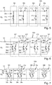
- circuit 32d according to Fig. 6 a kind of bipolar design is shown.
- the first and second sensor resistors 36d and 39d and 39d 'of the unit arrangements of the first and second types are connected in parallel branches, each with a diode 41d and 42d or 41d' and 42d 'in front, these diodes 41d and 42d in the parallel Branches face each other. Zener diodes could no longer be used here.
- the advantage of this solution is the higher resolution accuracy compared to the previously described unipolar design.
- the diodes 41d "and 42d" before this parallel connection are also connected in parallel and with opposite polarity to one another. There is also a parallel connection in the mesh M1 for the unit arrangement of the first type 38d.
- the opposite pairs of diodes 41d and 42d or 41d "and 42d" replace the previously simply switched diodes.
- FIG. 7 A further circuit 32e according to the invention is shown.
- diodes 41d and 42d are replaced by transistors 46e as alternative semiconductor components.
- Each juxtaposed pair of transistors 46e has, similar to that in FIG Fig. 6 with diodes 41 and 42, opposite transistors 46e. From a certain voltage, current can therefore only flow in one direction per transistor 46e. Otherwise, refer to the explanations Fig. 6 referred.
- FIG. 8 A universal sensor interface 48 is shown. With this, it is possible to query both conventional core temperature sensors, for example in accordance with the prior art mentioned at the beginning, and core temperature sensors 11 according to the invention with measuring resistor 34 and circuit 32.
- An operating unit I / O can be connected to a microcontroller MCU, as is known from the prior art for other such core temperature sensors.
- the voltage difference across the measuring resistor 34 is determined by means of an AD converter ADC. Furthermore, two DA converters DAC1 and DAC2 are provided. This voltage difference depends on the current, which in turn is determined by the size of the differential voltage of DAC1 and DAC2 and the current flowing through the sensor of the circuit 32. In the case of a core temperature sensor with only one temperature sensor or only one resistor, this is only determined by the value of the internal temperature-dependent resistor. With core temperature sensors according to 3 to 7 the number of sensed sensor resistors 36 and 39 in the core temperature sensor is determined by the size and polarity of the applied voltage. The number of stitches M requested and the sum of the in these currents flowing currents correspond to the total current flowing through the circuit 32.
- DAC2 can also be replaced by a ground connection.
- a simplification in such bipolar temperature sensor circuits would be that the voltage value provided by the DAC2 is replaced, for example, by a voltage divider which provides a voltage suitable for the sensor, with a symmetrical voltage distribution of the sensors, for example U adc / 2B .
- a further simplification would be to replace DAC1 by means of weighted resistors and controlled analog multiplexers, which ultimately corresponds to the implementation of DAC in a discrete design.
- a special embodiment would be, for example, the implementation using a so-called digital potentiometer or digipot.
Landscapes
- Physics & Mathematics (AREA)
- General Physics & Mathematics (AREA)
- Measuring Temperature Or Quantity Of Heat (AREA)
Priority Applications (1)
| Application Number | Priority Date | Filing Date | Title |
|---|---|---|---|
| PL18162780T PL3388802T3 (pl) | 2017-04-13 | 2018-03-20 | Układ połączeń i sposób pomiaru temperatury i czujnik temperatury |
Applications Claiming Priority (1)
| Application Number | Priority Date | Filing Date | Title |
|---|---|---|---|
| DE102017206407.2A DE102017206407B3 (de) | 2017-04-13 | 2017-04-13 | Schaltung und Verfahren zur Temperaturmessung und Temperaturfühler |
Publications (2)
| Publication Number | Publication Date |
|---|---|
| EP3388802A1 EP3388802A1 (de) | 2018-10-17 |
| EP3388802B1 true EP3388802B1 (de) | 2020-04-29 |
Family
ID=61691867
Family Applications (1)
| Application Number | Title | Priority Date | Filing Date |
|---|---|---|---|
| EP18162780.3A Active EP3388802B1 (de) | 2017-04-13 | 2018-03-20 | Schaltung und verfahren zur temperaturmessung und temperaturfühler |
Country Status (4)
| Country | Link |
|---|---|
| EP (1) | EP3388802B1 (pl) |
| DE (1) | DE102017206407B3 (pl) |
| ES (1) | ES2803950T3 (pl) |
| PL (1) | PL3388802T3 (pl) |
Family Cites Families (8)
| Publication number | Priority date | Publication date | Assignee | Title |
|---|---|---|---|---|
| SE469857B (sv) | 1992-02-07 | 1993-09-27 | Electrolux Ab | Temperaturprob avsedd att införas i en matvara som skall värmebehandlas jämte en ugn för behandling av matvaror innefattande en temperaturprob |
| DE4232245C2 (de) | 1992-09-25 | 2001-08-23 | Bernd Milzarek | Schaltung, Abschlußschaltung und Einrichtung zur Temperaturüberwachung |
| US20070029976A1 (en) * | 2005-07-19 | 2007-02-08 | Garcia Jorge L | Method and apparatus for monitoring battery cell temperature |
| ES2368507T3 (es) * | 2007-11-22 | 2011-11-17 | Whirlpool Corporation | Bus de sensores analógico. |
| DE102010063712A1 (de) * | 2010-12-21 | 2012-06-21 | BSH Bosch und Siemens Hausgeräte GmbH | Anordnung und Verfahren zur Datenerfassung in einem Gargerät |
| DE102011079098A1 (de) | 2011-07-13 | 2013-01-17 | BSH Bosch und Siemens Hausgeräte GmbH | Widerstandsmessung, insbesondere Temperaturbestimmung anhand temperaturabhängiger Widerstände |
| DE102011079217A1 (de) | 2011-07-15 | 2013-01-17 | BSH Bosch und Siemens Hausgeräte GmbH | Widerstandsmessung, insbesondere Temperaturbestimmung anhand temperaturabhängiger Widerstände |
| DE102012112855B4 (de) | 2012-12-21 | 2022-11-17 | Rational Ag | Gargerätmesseinheit mit mehreren Sensoren und Verfahren zur Ermittlung einer physikalischen Messgröße |
-
2017
- 2017-04-13 DE DE102017206407.2A patent/DE102017206407B3/de not_active Expired - Fee Related
-
2018
- 2018-03-20 PL PL18162780T patent/PL3388802T3/pl unknown
- 2018-03-20 ES ES18162780T patent/ES2803950T3/es active Active
- 2018-03-20 EP EP18162780.3A patent/EP3388802B1/de active Active
Non-Patent Citations (1)
| Title |
|---|
| None * |
Also Published As
| Publication number | Publication date |
|---|---|
| ES2803950T3 (es) | 2021-02-01 |
| PL3388802T3 (pl) | 2020-11-02 |
| EP3388802A1 (de) | 2018-10-17 |
| DE102017206407B3 (de) | 2018-07-05 |
Similar Documents
| Publication | Publication Date | Title |
|---|---|---|
| EP2664905B1 (de) | Temperaturmesseinrichtung, elektrisches Gerät mit einer solchen Temperaturmesseinrichtung und Verfahren zur Temperaturmessung | |
| DE202013011690U1 (de) | Messwiderstand | |
| DE69300966T2 (de) | Temperaturmesser und backofen damit versehen. | |
| DE102016202500A1 (de) | Batteriesensor, Verfahren zum Kalibrieren eines Messwiderstands und Verwendung | |
| DE2139999A1 (de) | Zustandsfuhlerschaltung in Brücken anordnung | |
| EP0189086A2 (de) | Glühelement | |
| DE102020105475A1 (de) | Temperaturmessgerät mit selbständiger Messsondenerkennung | |
| EP2741061A1 (de) | Verfahren und Vorrichtung zum Bestimmen einer effektiven Kerntemperatur eines Garguts | |
| DE69007511T2 (de) | Vorrichtung in einem Kochherd oder in einer Wärmeplatte für Kochzwecke. | |
| DE102017206407B3 (de) | Schaltung und Verfahren zur Temperaturmessung und Temperaturfühler | |
| EP2559981B1 (de) | Widerstandsmessung, insbesondere Temperaturbestimmung anhand temperaturabhängiger Widerstände | |
| EP2639511B1 (de) | Verfahren zum Betreiben eines Gargeräts mit anschließbarem Bratenthermometer und Gargerät | |
| WO2011131374A2 (de) | Temperaturüberwachungssystem | |
| WO2010049298A1 (de) | Widerstandsmessung eines von einer messgrösse abhängigen widerstandselements | |
| EP3786599A1 (de) | Messeinrichtung zur bestimmung von temperaturbedingten widerstandsänderungen sowie schlauchsystem mit einer solchen messeinrichtung | |
| EP2559982B1 (de) | System und Verfahren zur Widerstandsbestimmung von drei temperaturabhängigen Widerständen | |
| DE1640295C3 (de) | Schaltungsanordnung zur Einstellung einer mehrstellig dekadisch abgestuften Spannung | |
| DE2642036C3 (de) | Elektronische Anordnung zur Erzeugung von Schaltimpulsen mit einstellbarem Ein-Aus-Schaltverhältnis | |
| DE102004063207A1 (de) | Temperatursensor | |
| DE1538302A1 (de) | Temperaturkompensiertes Pruefgeraet fuer Spannungskonstanthalter | |
| DE19649157A1 (de) | Vorrichtung zur Heizungsregelung | |
| DE10033472A1 (de) | Optisches Gerät | |
| DE102022122142A1 (de) | Verfahren zur Heizungssteuerung einer Heizschleife eines Lenkrades, zugehörige Anordnung und Verwendung | |
| DE60319160T2 (de) | Steuerschaltung für hf-schaltungen auf diodenbasis | |
| DE20011944U1 (de) | Optisches Gerät |
Legal Events
| Date | Code | Title | Description |
|---|---|---|---|
| PUAI | Public reference made under article 153(3) epc to a published international application that has entered the european phase |
Free format text: ORIGINAL CODE: 0009012 |
|
| STAA | Information on the status of an ep patent application or granted ep patent |
Free format text: STATUS: THE APPLICATION HAS BEEN PUBLISHED |
|
| AK | Designated contracting states |
Kind code of ref document: A1 Designated state(s): AL AT BE BG CH CY CZ DE DK EE ES FI FR GB GR HR HU IE IS IT LI LT LU LV MC MK MT NL NO PL PT RO RS SE SI SK SM TR |
|
| AX | Request for extension of the european patent |
Extension state: BA ME |
|
| STAA | Information on the status of an ep patent application or granted ep patent |
Free format text: STATUS: REQUEST FOR EXAMINATION WAS MADE |
|
| 17P | Request for examination filed |
Effective date: 20190410 |
|
| RBV | Designated contracting states (corrected) |
Designated state(s): AL AT BE BG CH CY CZ DE DK EE ES FI FR GB GR HR HU IE IS IT LI LT LU LV MC MK MT NL NO PL PT RO RS SE SI SK SM TR |
|
| GRAP | Despatch of communication of intention to grant a patent |
Free format text: ORIGINAL CODE: EPIDOSNIGR1 |
|
| RIC1 | Information provided on ipc code assigned before grant |
Ipc: G01K 7/20 20060101ALI20191004BHEP Ipc: F24C 7/08 20060101ALI20191004BHEP Ipc: G01K 1/02 20060101AFI20191004BHEP |
|
| STAA | Information on the status of an ep patent application or granted ep patent |
Free format text: STATUS: GRANT OF PATENT IS INTENDED |
|
| INTG | Intention to grant announced |
Effective date: 20191114 |
|
| GRAS | Grant fee paid |
Free format text: ORIGINAL CODE: EPIDOSNIGR3 |
|
| RAP1 | Party data changed (applicant data changed or rights of an application transferred) |
Owner name: E.G.O. ELEKTRO-GERAETEBAU GMBH |
|
| GRAA | (expected) grant |
Free format text: ORIGINAL CODE: 0009210 |
|
| STAA | Information on the status of an ep patent application or granted ep patent |
Free format text: STATUS: THE PATENT HAS BEEN GRANTED |
|
| AK | Designated contracting states |
Kind code of ref document: B1 Designated state(s): AL AT BE BG CH CY CZ DE DK EE ES FI FR GB GR HR HU IE IS IT LI LT LU LV MC MK MT NL NO PL PT RO RS SE SI SK SM TR |
|
| REG | Reference to a national code |
Ref country code: GB Ref legal event code: FG4D Free format text: NOT ENGLISH |
|
| REG | Reference to a national code |
Ref country code: CH Ref legal event code: EP |
|
| REG | Reference to a national code |
Ref country code: DE Ref legal event code: R096 Ref document number: 502018001296 Country of ref document: DE |
|
| REG | Reference to a national code |
Ref country code: AT Ref legal event code: REF Ref document number: 1264016 Country of ref document: AT Kind code of ref document: T Effective date: 20200515 |
|
| REG | Reference to a national code |
Ref country code: IE Ref legal event code: FG4D Free format text: LANGUAGE OF EP DOCUMENT: GERMAN |
|
| REG | Reference to a national code |
Ref country code: NL Ref legal event code: MP Effective date: 20200429 |
|
| REG | Reference to a national code |
Ref country code: LT Ref legal event code: MG4D |
|
| PG25 | Lapsed in a contracting state [announced via postgrant information from national office to epo] |
Ref country code: LT Free format text: LAPSE BECAUSE OF FAILURE TO SUBMIT A TRANSLATION OF THE DESCRIPTION OR TO PAY THE FEE WITHIN THE PRESCRIBED TIME-LIMIT Effective date: 20200429 Ref country code: PT Free format text: LAPSE BECAUSE OF FAILURE TO SUBMIT A TRANSLATION OF THE DESCRIPTION OR TO PAY THE FEE WITHIN THE PRESCRIBED TIME-LIMIT Effective date: 20200831 Ref country code: GR Free format text: LAPSE BECAUSE OF FAILURE TO SUBMIT A TRANSLATION OF THE DESCRIPTION OR TO PAY THE FEE WITHIN THE PRESCRIBED TIME-LIMIT Effective date: 20200730 Ref country code: SE Free format text: LAPSE BECAUSE OF FAILURE TO SUBMIT A TRANSLATION OF THE DESCRIPTION OR TO PAY THE FEE WITHIN THE PRESCRIBED TIME-LIMIT Effective date: 20200429 Ref country code: NO Free format text: LAPSE BECAUSE OF FAILURE TO SUBMIT A TRANSLATION OF THE DESCRIPTION OR TO PAY THE FEE WITHIN THE PRESCRIBED TIME-LIMIT Effective date: 20200729 Ref country code: IS Free format text: LAPSE BECAUSE OF FAILURE TO SUBMIT A TRANSLATION OF THE DESCRIPTION OR TO PAY THE FEE WITHIN THE PRESCRIBED TIME-LIMIT Effective date: 20200829 Ref country code: FI Free format text: LAPSE BECAUSE OF FAILURE TO SUBMIT A TRANSLATION OF THE DESCRIPTION OR TO PAY THE FEE WITHIN THE PRESCRIBED TIME-LIMIT Effective date: 20200429 |
|
| PG25 | Lapsed in a contracting state [announced via postgrant information from national office to epo] |
Ref country code: RS Free format text: LAPSE BECAUSE OF FAILURE TO SUBMIT A TRANSLATION OF THE DESCRIPTION OR TO PAY THE FEE WITHIN THE PRESCRIBED TIME-LIMIT Effective date: 20200429 Ref country code: HR Free format text: LAPSE BECAUSE OF FAILURE TO SUBMIT A TRANSLATION OF THE DESCRIPTION OR TO PAY THE FEE WITHIN THE PRESCRIBED TIME-LIMIT Effective date: 20200429 Ref country code: BG Free format text: LAPSE BECAUSE OF FAILURE TO SUBMIT A TRANSLATION OF THE DESCRIPTION OR TO PAY THE FEE WITHIN THE PRESCRIBED TIME-LIMIT Effective date: 20200729 Ref country code: LV Free format text: LAPSE BECAUSE OF FAILURE TO SUBMIT A TRANSLATION OF THE DESCRIPTION OR TO PAY THE FEE WITHIN THE PRESCRIBED TIME-LIMIT Effective date: 20200429 |
|
| PG25 | Lapsed in a contracting state [announced via postgrant information from national office to epo] |
Ref country code: AL Free format text: LAPSE BECAUSE OF FAILURE TO SUBMIT A TRANSLATION OF THE DESCRIPTION OR TO PAY THE FEE WITHIN THE PRESCRIBED TIME-LIMIT Effective date: 20200429 Ref country code: NL Free format text: LAPSE BECAUSE OF FAILURE TO SUBMIT A TRANSLATION OF THE DESCRIPTION OR TO PAY THE FEE WITHIN THE PRESCRIBED TIME-LIMIT Effective date: 20200429 |
|
| PG25 | Lapsed in a contracting state [announced via postgrant information from national office to epo] |
Ref country code: RO Free format text: LAPSE BECAUSE OF FAILURE TO SUBMIT A TRANSLATION OF THE DESCRIPTION OR TO PAY THE FEE WITHIN THE PRESCRIBED TIME-LIMIT Effective date: 20200429 Ref country code: CZ Free format text: LAPSE BECAUSE OF FAILURE TO SUBMIT A TRANSLATION OF THE DESCRIPTION OR TO PAY THE FEE WITHIN THE PRESCRIBED TIME-LIMIT Effective date: 20200429 Ref country code: EE Free format text: LAPSE BECAUSE OF FAILURE TO SUBMIT A TRANSLATION OF THE DESCRIPTION OR TO PAY THE FEE WITHIN THE PRESCRIBED TIME-LIMIT Effective date: 20200429 Ref country code: SM Free format text: LAPSE BECAUSE OF FAILURE TO SUBMIT A TRANSLATION OF THE DESCRIPTION OR TO PAY THE FEE WITHIN THE PRESCRIBED TIME-LIMIT Effective date: 20200429 Ref country code: DK Free format text: LAPSE BECAUSE OF FAILURE TO SUBMIT A TRANSLATION OF THE DESCRIPTION OR TO PAY THE FEE WITHIN THE PRESCRIBED TIME-LIMIT Effective date: 20200429 |
|
| REG | Reference to a national code |
Ref country code: ES Ref legal event code: FG2A Ref document number: 2803950 Country of ref document: ES Kind code of ref document: T3 Effective date: 20210201 Ref country code: DE Ref legal event code: R097 Ref document number: 502018001296 Country of ref document: DE |
|
| PG25 | Lapsed in a contracting state [announced via postgrant information from national office to epo] |
Ref country code: SK Free format text: LAPSE BECAUSE OF FAILURE TO SUBMIT A TRANSLATION OF THE DESCRIPTION OR TO PAY THE FEE WITHIN THE PRESCRIBED TIME-LIMIT Effective date: 20200429 |
|
| PLBE | No opposition filed within time limit |
Free format text: ORIGINAL CODE: 0009261 |
|
| STAA | Information on the status of an ep patent application or granted ep patent |
Free format text: STATUS: NO OPPOSITION FILED WITHIN TIME LIMIT |
|
| 26N | No opposition filed |
Effective date: 20210201 |
|
| PG25 | Lapsed in a contracting state [announced via postgrant information from national office to epo] |
Ref country code: SI Free format text: LAPSE BECAUSE OF FAILURE TO SUBMIT A TRANSLATION OF THE DESCRIPTION OR TO PAY THE FEE WITHIN THE PRESCRIBED TIME-LIMIT Effective date: 20200429 |
|
| PG25 | Lapsed in a contracting state [announced via postgrant information from national office to epo] |
Ref country code: MC Free format text: LAPSE BECAUSE OF FAILURE TO SUBMIT A TRANSLATION OF THE DESCRIPTION OR TO PAY THE FEE WITHIN THE PRESCRIBED TIME-LIMIT Effective date: 20200429 |
|
| REG | Reference to a national code |
Ref country code: CH Ref legal event code: PL |
|
| REG | Reference to a national code |
Ref country code: BE Ref legal event code: MM Effective date: 20210331 |
|
| PG25 | Lapsed in a contracting state [announced via postgrant information from national office to epo] |
Ref country code: CH Free format text: LAPSE BECAUSE OF NON-PAYMENT OF DUE FEES Effective date: 20210331 Ref country code: IE Free format text: LAPSE BECAUSE OF NON-PAYMENT OF DUE FEES Effective date: 20210320 Ref country code: LI Free format text: LAPSE BECAUSE OF NON-PAYMENT OF DUE FEES Effective date: 20210331 Ref country code: LU Free format text: LAPSE BECAUSE OF NON-PAYMENT OF DUE FEES Effective date: 20210320 |
|
| PG25 | Lapsed in a contracting state [announced via postgrant information from national office to epo] |
Ref country code: BE Free format text: LAPSE BECAUSE OF NON-PAYMENT OF DUE FEES Effective date: 20210331 |
|
| GBPC | Gb: european patent ceased through non-payment of renewal fee |
Effective date: 20220320 |
|
| PG25 | Lapsed in a contracting state [announced via postgrant information from national office to epo] |
Ref country code: GB Free format text: LAPSE BECAUSE OF NON-PAYMENT OF DUE FEES Effective date: 20220320 |
|
| PG25 | Lapsed in a contracting state [announced via postgrant information from national office to epo] |
Ref country code: CY Free format text: LAPSE BECAUSE OF FAILURE TO SUBMIT A TRANSLATION OF THE DESCRIPTION OR TO PAY THE FEE WITHIN THE PRESCRIBED TIME-LIMIT Effective date: 20200429 |
|
| PG25 | Lapsed in a contracting state [announced via postgrant information from national office to epo] |
Ref country code: HU Free format text: LAPSE BECAUSE OF FAILURE TO SUBMIT A TRANSLATION OF THE DESCRIPTION OR TO PAY THE FEE WITHIN THE PRESCRIBED TIME-LIMIT; INVALID AB INITIO Effective date: 20180320 |
|
| PG25 | Lapsed in a contracting state [announced via postgrant information from national office to epo] |
Ref country code: MK Free format text: LAPSE BECAUSE OF FAILURE TO SUBMIT A TRANSLATION OF THE DESCRIPTION OR TO PAY THE FEE WITHIN THE PRESCRIBED TIME-LIMIT Effective date: 20200429 |
|
| REG | Reference to a national code |
Ref country code: AT Ref legal event code: MM01 Ref document number: 1264016 Country of ref document: AT Kind code of ref document: T Effective date: 20230320 |
|
| PG25 | Lapsed in a contracting state [announced via postgrant information from national office to epo] |
Ref country code: AT Free format text: LAPSE BECAUSE OF NON-PAYMENT OF DUE FEES Effective date: 20230320 |
|
| PG25 | Lapsed in a contracting state [announced via postgrant information from national office to epo] |
Ref country code: AT Free format text: LAPSE BECAUSE OF NON-PAYMENT OF DUE FEES Effective date: 20230320 |
|
| PG25 | Lapsed in a contracting state [announced via postgrant information from national office to epo] |
Ref country code: MT Free format text: LAPSE BECAUSE OF FAILURE TO SUBMIT A TRANSLATION OF THE DESCRIPTION OR TO PAY THE FEE WITHIN THE PRESCRIBED TIME-LIMIT Effective date: 20200429 |
|
| PGFP | Annual fee paid to national office [announced via postgrant information from national office to epo] |
Ref country code: ES Payment date: 20250416 Year of fee payment: 8 |
|
| PGFP | Annual fee paid to national office [announced via postgrant information from national office to epo] |
Ref country code: IT Payment date: 20250331 Year of fee payment: 8 |
|
| PGFP | Annual fee paid to national office [announced via postgrant information from national office to epo] |
Ref country code: DE Payment date: 20260320 Year of fee payment: 9 |
|
| PGFP | Annual fee paid to national office [announced via postgrant information from national office to epo] |
Ref country code: AT Payment date: 20260410 Year of fee payment: 5 |
|
| PGFP | Annual fee paid to national office [announced via postgrant information from national office to epo] |
Ref country code: FR Payment date: 20260325 Year of fee payment: 9 |
|
| PGFP | Annual fee paid to national office [announced via postgrant information from national office to epo] |
Ref country code: TR Payment date: 20260316 Year of fee payment: 9 |
|
| PGFP | Annual fee paid to national office [announced via postgrant information from national office to epo] |
Ref country code: PL Payment date: 20260306 Year of fee payment: 9 |