EP3388700B1 - Connecting rod bearing and bearing device - Google Patents
Connecting rod bearing and bearing device Download PDFInfo
- Publication number
- EP3388700B1 EP3388700B1 EP18167246.0A EP18167246A EP3388700B1 EP 3388700 B1 EP3388700 B1 EP 3388700B1 EP 18167246 A EP18167246 A EP 18167246A EP 3388700 B1 EP3388700 B1 EP 3388700B1
- Authority
- EP
- European Patent Office
- Prior art keywords
- bearing
- connecting rod
- half bearing
- groove
- cylindrical
- Prior art date
- Legal status (The legal status is an assumption and is not a legal conclusion. Google has not performed a legal analysis and makes no representation as to the accuracy of the status listed.)
- Active
Links
Images


Classifications
-
- F—MECHANICAL ENGINEERING; LIGHTING; HEATING; WEAPONS; BLASTING
- F16—ENGINEERING ELEMENTS AND UNITS; GENERAL MEASURES FOR PRODUCING AND MAINTAINING EFFECTIVE FUNCTIONING OF MACHINES OR INSTALLATIONS; THERMAL INSULATION IN GENERAL
- F16C—SHAFTS; FLEXIBLE SHAFTS; ELEMENTS OR CRANKSHAFT MECHANISMS; ROTARY BODIES OTHER THAN GEARING ELEMENTS; BEARINGS
- F16C9/00—Bearings for crankshafts or connecting-rods; Attachment of connecting-rods
- F16C9/04—Connecting-rod bearings; Attachments thereof
-
- F—MECHANICAL ENGINEERING; LIGHTING; HEATING; WEAPONS; BLASTING
- F01—MACHINES OR ENGINES IN GENERAL; ENGINE PLANTS IN GENERAL; STEAM ENGINES
- F01M—LUBRICATING OF MACHINES OR ENGINES IN GENERAL; LUBRICATING INTERNAL COMBUSTION ENGINES; CRANKCASE VENTILATING
- F01M1/00—Pressure lubrication
- F01M1/06—Lubricating systems characterised by the provision therein of crankshafts or connecting rods with lubricant passageways, e.g. bores
-
- F—MECHANICAL ENGINEERING; LIGHTING; HEATING; WEAPONS; BLASTING
- F16—ENGINEERING ELEMENTS AND UNITS; GENERAL MEASURES FOR PRODUCING AND MAINTAINING EFFECTIVE FUNCTIONING OF MACHINES OR INSTALLATIONS; THERMAL INSULATION IN GENERAL
- F16C—SHAFTS; FLEXIBLE SHAFTS; ELEMENTS OR CRANKSHAFT MECHANISMS; ROTARY BODIES OTHER THAN GEARING ELEMENTS; BEARINGS
- F16C17/00—Sliding-contact bearings for exclusively rotary movement
- F16C17/02—Sliding-contact bearings for exclusively rotary movement for radial load only
- F16C17/022—Sliding-contact bearings for exclusively rotary movement for radial load only with a pair of essentially semicircular bearing sleeves
-
- F—MECHANICAL ENGINEERING; LIGHTING; HEATING; WEAPONS; BLASTING
- F16—ENGINEERING ELEMENTS AND UNITS; GENERAL MEASURES FOR PRODUCING AND MAINTAINING EFFECTIVE FUNCTIONING OF MACHINES OR INSTALLATIONS; THERMAL INSULATION IN GENERAL
- F16C—SHAFTS; FLEXIBLE SHAFTS; ELEMENTS OR CRANKSHAFT MECHANISMS; ROTARY BODIES OTHER THAN GEARING ELEMENTS; BEARINGS
- F16C33/00—Parts of bearings; Special methods for making bearings or parts thereof
- F16C33/02—Parts of sliding-contact bearings
- F16C33/04—Brasses; Bushes; Linings
- F16C33/046—Brasses; Bushes; Linings divided or split, e.g. half-bearings or rolled sleeves
-
- F—MECHANICAL ENGINEERING; LIGHTING; HEATING; WEAPONS; BLASTING
- F16—ENGINEERING ELEMENTS AND UNITS; GENERAL MEASURES FOR PRODUCING AND MAINTAINING EFFECTIVE FUNCTIONING OF MACHINES OR INSTALLATIONS; THERMAL INSULATION IN GENERAL
- F16C—SHAFTS; FLEXIBLE SHAFTS; ELEMENTS OR CRANKSHAFT MECHANISMS; ROTARY BODIES OTHER THAN GEARING ELEMENTS; BEARINGS
- F16C33/00—Parts of bearings; Special methods for making bearings or parts thereof
- F16C33/02—Parts of sliding-contact bearings
- F16C33/04—Brasses; Bushes; Linings
- F16C33/06—Sliding surface mainly made of metal
- F16C33/10—Construction relative to lubrication
- F16C33/1025—Construction relative to lubrication with liquid, e.g. oil, as lubricant
- F16C33/1045—Details of supply of the liquid to the bearing
-
- F—MECHANICAL ENGINEERING; LIGHTING; HEATING; WEAPONS; BLASTING
- F16—ENGINEERING ELEMENTS AND UNITS; GENERAL MEASURES FOR PRODUCING AND MAINTAINING EFFECTIVE FUNCTIONING OF MACHINES OR INSTALLATIONS; THERMAL INSULATION IN GENERAL
- F16C—SHAFTS; FLEXIBLE SHAFTS; ELEMENTS OR CRANKSHAFT MECHANISMS; ROTARY BODIES OTHER THAN GEARING ELEMENTS; BEARINGS
- F16C33/00—Parts of bearings; Special methods for making bearings or parts thereof
- F16C33/02—Parts of sliding-contact bearings
- F16C33/04—Brasses; Bushes; Linings
- F16C33/06—Sliding surface mainly made of metal
- F16C33/10—Construction relative to lubrication
- F16C33/1025—Construction relative to lubrication with liquid, e.g. oil, as lubricant
- F16C33/106—Details of distribution or circulation inside the bearings, e.g. details of the bearing surfaces to affect flow or pressure of the liquid
- F16C33/1065—Grooves on a bearing surface for distributing or collecting the liquid
-
- F—MECHANICAL ENGINEERING; LIGHTING; HEATING; WEAPONS; BLASTING
- F01—MACHINES OR ENGINES IN GENERAL; ENGINE PLANTS IN GENERAL; STEAM ENGINES
- F01M—LUBRICATING OF MACHINES OR ENGINES IN GENERAL; LUBRICATING INTERNAL COMBUSTION ENGINES; CRANKCASE VENTILATING
- F01M1/00—Pressure lubrication
- F01M1/06—Lubricating systems characterised by the provision therein of crankshafts or connecting rods with lubricant passageways, e.g. bores
- F01M2001/066—Connecting rod with passageways
-
- F—MECHANICAL ENGINEERING; LIGHTING; HEATING; WEAPONS; BLASTING
- F16—ENGINEERING ELEMENTS AND UNITS; GENERAL MEASURES FOR PRODUCING AND MAINTAINING EFFECTIVE FUNCTIONING OF MACHINES OR INSTALLATIONS; THERMAL INSULATION IN GENERAL
- F16C—SHAFTS; FLEXIBLE SHAFTS; ELEMENTS OR CRANKSHAFT MECHANISMS; ROTARY BODIES OTHER THAN GEARING ELEMENTS; BEARINGS
- F16C2360/00—Engines or pumps
- F16C2360/22—Internal combustion engines
Definitions
- the present invention relates to a connecting rod bearing of an internal combustion engine. More particularly, the present invention relates to a connecting rod bearing configured so that lubricating oil supplied to an inner peripheral surface of a main bearing which supports a crank shaft is supplied, through an internal lubricating oil path of the crank shaft, to an inner peripheral surface of the connecting rod bearing which rotatably supports a crank pin of the crank shaft coupled to a connecting rod.
- the present invention also relates to a bearing device using this connecting rod bearing.
- An internal combustion engine has a connecting rod which couples a piston and a crank shaft to convert reciprocation of the piston into rotational motion of the crank shaft.
- the connecting rod includes a connecting rod body portion and a connecting rod cap portion (the connecting rod body portion may be further divided into several parts).
- the connecting rod At one end of the connecting rod body portion, the connecting rod has a small end portion which supports a piston pin, and the small end portion has a bush holding hole.
- the other end of the connecting rod body portion is combined with the connecting rod cap portion by a bolt to form a large end portion which supports a crank pin.
- the large end portion has a cylindrical bearing holding hole which holds a connecting rod bearing and which is formed by a semi-cylindrical first bearing holding hole in the connecting rod body portion and a semi-cylindrical second bearing holding hole in the connecting rod cap portion when end faces of the connecting rod body portion and the connecting rod cap portion are butted against each other.
- a cylindrical bush bearing is inserted into the bush holding hole in the small end portion of the connecting rod, and the piston pin is thereby supported.
- a pair of half bearings which are formed so as to engage with the shapes of the first bearing holding hole of the connecting rod body portion and the second bearing holding hole of the connecting rod cap portion, respectively, are inserted into the bearing holding hole of the large end portion.
- the first bearing holding hole includes a first supply groove extending from a circumferential end face on a forward side of a rotation direction of the crank pin toward a circumferentially central portion side, and a second supply groove extending from a circumferential end face on a backward side of the rotation direction of the crank pin toward the circumferentially central portion side.
- the second bearing holding hole includes a third supply groove extending over the entire length in a circumferential direction.
- the third supply groove is brought into communication with the first supply groove and the second supply groove at the places where their respective circumferential end faces are butted against each other.
- the connecting rod includes a communication path which allows communication between the small end portion and one of the first supply groove, the second supply groove, and the third supply groove in order to supply lubricating oil to the small end portion of the connecting rod.
- the crank pin includes a cylindrical barrel portion, a lubricating oil path extending through the cylindrical barrel portion, and at least one exit opening of the lubricating oil path formed on an outer peripheral surface of the cylindrical barrel portion.
- the exit opening communicates with a space between the outer peripheral surface of the cylindrical barrel portion and a slide surface of the connecting rod bearing. Therefore, the lubricating oil is fed by pressure to the connecting rod bearing via the lubricating oil path and the exit opening.
- the half bearing (hereinafter referred to as a first half bearing) held onto the connecting rod body portion side, of the connecting rod bearing composed of the pair of half bearings, includes a first partial groove extending from the circumferential end face on a forward side of the rotation direction of the crank pin toward a circumferentially central portion side, and a second partial groove extending from the circumferential end face on a backward side of the rotation direction of the crank pin toward the circumferentially central portion side, and also includes at least one oil hole passing through from an inner surface of the first partial groove or the second partial groove to a bearing outer peripheral surface of the first half bearing.
- the half bearing (hereinafter referred to as a second half bearing) held onto the connecting rod cap portion side includes an oil groove extending over the entire length in the circumferential direction of the second half bearing, and also includes at least one oil hole passing through from an inner surface of the oil groove to a bearing outer peripheral surface of the second half bearing.
- a part of the lubricating oil fed by pressure to the connecting rod bearing is supplied to the first supply groove and the second supply groove formed in the first bearing holding hole of the connecting rod and to the third supply groove formed in the second bearing holding hole, through the first partial groove and the second partial groove formed in the first half bearing, the oil groove formed in the second half bearing, and the oil holes formed in the pair of half bearings, and further supplied to the connecting rod small end portion through the communication path formed in the connecting rod.
- the connecting rod bearing includes a back metal layer and a slide layer, and the slide layer constitutes slide surfaces of the half bearings.
- the slide layer is made of a bearing alloy such as a white alloy (tin alloy), an aluminum alloy, or a copper alloy.
- the surface of the slide layer may be covered with a surface layer (overlay layer) of a lead-based material, a tin-based material, an aluminum alloy, synthetic resin, or the like by means of electroplating, vacuum deposition, or spraying.
- a first partial groove 115 extending from a circumferential end face 114 on a forward side of a rotation direction R of a crank pin 50 toward a circumferentially central portion side
- a second partial groove 117 extending from a circumferential end face 116 on a backward side of the rotation direction R of the crank pin 50 toward the circumferentially central portion side.
- Each of the first partial groove 115 and the second partial groove 117 becomes gently shallow and ends on the bearing slide surface 113 (as a terminal), so that the slide surface 113 is formed between an end 115a of the first partial groove 115 on its circumferentially central portion side and an end 117a of the second partial groove 117 on its circumferentially central portion side.
- an exit opening 52 of the crank pin 50 communicates with a space between an outer peripheral surface 54 of a cylindrical barrel portion of the crank pin and the slide surface 113 of the connecting rod bearing.
- the exit opening 52 of the crank pin 50 is located above the slide surface 113 between the circumferentially central portion side end 115a of the first partial groove 115 and the circumferentially central portion side end 117a of the second partial groove 117, the space S between the outer peripheral surface 54 of the cylindrical barrel portion of the crank pin 50 and the slide surface 113 of the first half bearing 110 is small, and therefore, the pressure of lubricating oil near the exit opening 52 in a lubricating oil path 51 is in an extremely high state due to the effect of centrifugal force resulting from the rotation of the crank pin 50.
- the lubricating oil instantaneously flows rapidly into the first partial groove 115 from the lubricating oil path 51 due to the difference between the pressure of the lubricating oil within the lubricating oil path 51 of the crank pin 50, and the pressure of the lubricating oil within the space S between the outer peripheral surface 54 of the cylindrical barrel portion of the crank pin 50 and the vicinity of the circumferential end 115a on a circumferential direction central portion side of the first partial groove 115.
- the pressure of the lubricating oil which has flowed out from the lubricating oil path 51 rapidly decreases, and becomes smaller than or equal to vapor pressure, thereby producing cavities (air bubbles) C in the lubricating oil.
- the cavities C break when the pressure becomes equal to or more than the vapor pressure, and pressure flow (micro jet) of the lubricating oil is generated.
- a slide layer 181 located in the vicinity of the circumferential end 115a is eroded (cavitation erosion).
- the slide layer 181 of the connecting rod bearing is relatively soft, and therefore easily eroded.
- the surface state of the eroded slide layer 181 appears rough in general.
- the rough surface has an adverse effect on the formation of a lubricating oil film, and leads to secondary damage such as seizure of a bearing.
- the slide layer 181 which has peeled due to the erosion becomes mixed to the lubricating oil as a foreign matter, and may damage the slide surface of the connecting rod bearing and other components.
- an object of the present invention is to provide a connecting rod bearing and a bearing device in which cavitation erosion does not occur in a slide layer even when cavities are produced in lubricating oil.
- a connecting rod bearing for rotatably supporting a crank pin of a crank shaft of an internal combustion engine, the crank pin including a cylindrical barrel portion, a lubricating oil path extending through the cylindrical barrel portion, and at least one exit opening of the lubricating oil path formed on an outer peripheral surface of the cylindrical barrel portion
- the connecting rod bearing includes a first half bearing and a second half bearing, the first half bearing and the second half bearing being combined into a cylindrical shape by bringing respective circumferential end faces of the first half bearing and the second half bearing into contact with each other, each of the first half bearing and the second half bearing including a back metal layer and a slide layer, the slide layer constituting a slide surface of each half bearing, the second half bearing including, on the slide surface (inner peripheral surface) side, an oil groove extending over the entire length of a circumferential direction of the second half bearing, and at least one oil hole passing through from an inner surface of the oil groove to a
- cylindrical depression can be formed so that, in a cross section including the axial center line of the cylindrical depression and perpendicular to the connecting rod bearing, an angle ( ⁇ 2) of a side surface of the cylindrical depression with respect to a line perpendicular to the axial center line is 85° to 95°.
- Fig. 1 is a sectional view showing the structure of a bearing device 2 including a crank pin 50, a connecting rod 70, and a connecting rod bearing 1 internally installed in a large end portion of the connecting rod 70.
- the crank pin 50 includes a cylindrical barrel portion 55, a lubricating oil path 51 extending through the cylindrical barrel portion 55, and at least one exit opening 52 of the lubricating oil path 51 formed on an outer peripheral surface 54 of the cylindrical barrel portion 55.
- the connecting rod 70 has a cylindrical bearing holding hole 77 which holds the connecting rod bearing 1 and is formed when a semi-cylindrical first bearing holding hole 73 formed in an end face of a connecting rod body portion 72 and a semi-cylindrical second bearing holding hole 75 formed in an end face of a connecting rod cap portion 74 are butted against each other.
- the first bearing holding hole 73 includes a first supply groove 78a extending from an end face 72a on a forward side of a rotation direction of the crank pin 50 toward a circumferentially central portion side, and a second supply groove 78b extending from an end face 72b on a backward side of the rotation direction of the crank pin 50 toward the circumferentially central portion side.
- the second bearing holding hole 75 includes a third supply groove 78c extending over the entire length in a circumferential direction.
- the third supply groove 78c is brought into communication with the first supply groove 78a and the second supply groove 78b by butting the end faces of the connecting rod body portion 72 and the connecting rod cap portion 74 against each other.
- the connecting rod body portion 72 includes a connecting rod small end portion which rotatably supports a piston pin (not shown), and also includes a communication path 79 which allows communication between the connecting rod small end portion and one of the first supply groove 78a, the second supply groove 78b, and the third supply groove 78c.
- a pair of half bearings (the connecting rod bearing 1) is inserted into an inner peripheral surface of the connecting rod 70.
- the pair of half bearings is formed so as to engage with the respective shapes of the first bearing holding hole 73 and the second bearing holding hole 75 of the connecting rod body portion 72 and the connecting rod cap portion 74 being divided, and are combined into a cylindrical shape by butting the end faces of the connecting rod body portion 72 and the connecting rod cap portion 74 against each other.
- a second half bearing 20 includes, on a slide surface 23 side, an oil groove 25 of a certain depth extending over the entire length in a circumferential direction of the second half bearing 20, and also includes at least one oil hole 29 formed in the oil groove 25 so as to pierce to a bearing outer peripheral surface 21.
- Fig. 3 shows a configuration on an inner surface side of a first half bearing 10 in Fig. 2 .
- Fig. 4 shows a configuration on an inner surface side of the second half bearing 20 in Fig. 2 .
- the first half bearing 10 includes, on a slide surface 13 side, a first partial groove 15 extending from a circumferential end face 14 on the forward side of the rotation direction R of the crank pin 50 toward a circumferentially central portion side, and a second partial groove 17 extending from a circumferential end face 16 on the backward side of the rotation direction R of the crank pin 50 toward the circumferentially central portion side.
- the first half bearing 10 also includes a cylindrical depression 18 formed so as to communicate with the first partial groove 15 at a circumferential end 15a on the circumferentially central portion side of the first partial groove 15.
- the slide surface 13 extends between a circumferential end 17a on a circumferentially central portion side of the second partial groove 17 of the first half bearing 10 and a circumferential end 18a on a circumferentially central portion side of the cylindrical depression 18, and two oil holes 19 are formed in the first partial groove 15 and the second partial groove 17, respectively, so as to pierce to a bearing outer peripheral surface 11.
- the depths of the first partial groove 15 and the second partial groove 17 measured as a radial direction distance from the slide surface 13 gradually decrease from the circumferential end face 14 and 16 sides of the first half bearing 10 toward the circumferentially central portion side.
- the first half bearing 10 and the second half bearing 20 become a cylindrical shape by butting their respective circumferential end faces 14, 16, 24, and 26 against each other.
- the oil groove 25 of the second half bearing 20 is brought into communication with the first partial groove 15 and the second partial groove 17 of the first half bearing 10 at the places where their respective circumferential end faces 14, 16, 24, and 26 are butted against each other.
- a part of the lubricating oil fed by pressure to the connecting rod bearing 1 is supplied to the first supply groove 78a and the second supply groove 78b formed in the first bearing holding hole 73 of the connecting rod 70 and to the third supply groove 78c formed in the second bearing holding hole 75, through the first partial groove 15 and the second partial groove 17 formed in the first half bearing 10, the oil groove 25 formed in the second half bearing 20, and the oil holes 19 and 29 formed in the pair of half bearings, and further supplied to the small end portion of the connecting rod 70 through the communication path 79 formed in the connecting rod 70.
- FIG. 2 shows the connecting rod bearing 1 composed of the first half bearing 10 and the second half bearing 20.
- the connecting rod bearing 1 has the following dimensions.
- the first half bearing 10 has the following dimensions.
- Thickness (T1) of a slide layer 81 0.5 mm
- Depth (D1) of the first partial groove at the communication portion 15a between the first partial groove 15 and the cylindrical depression 18 0.6 mm
- Depth (D2) of the cylindrical depression 18 3 mm
- a circumferential angle ( ⁇ 3) which defines the length of the second partial groove 17 from the circumferential end face 16 on the backward side of the rotation direction of the crank pin 50 to the circumferential end 17a on the circumferentially central portion side may be 10° to 50°.
- Each of the first half bearing 10 and the second half bearing 20 includes a back metal layer 82 and the slide layer 81, the slide layers 81 constitute slide surfaces 13 and 23 of the half bearings 10 and 20.
- the slide layer 81 is an alloy layer made of a white alloy (tin alloy), an aluminum alloy, a copper alloy, or the like.
- the back metal layer 82 can be an iron alloy such as hypoeutectoid steel in which the content of carbon is 0.05 to 0.35 percent by mass.
- the cylindrical depression 18 is formed adjacent to the circumferential end 15a on the circumferentially central portion side of the first partial groove 15.
- the aforementioned axial center line 18ax of the cylindrical depression 18 is formed so as to extend toward the center (axial center line) of the first half bearing 10.
- a circumferential angle ( ⁇ 1) of the slide surface between the circumferential end 17a on the circumferentially central portion side of the second partial groove 17 of the first half bearing 10 and the circumferential end 18a on the circumferentially central portion side of the cylindrical depression 18 is preferably 80° to 160° in order to support a load produced from a combustion chamber.
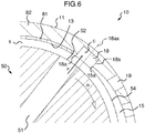
- Fig. 5 shows a state where the exit opening 52 of the crank pin 50 is located above the slide surface 13 formed between the circumferential end 17a on the circumferentially central portion side of the second partial groove 17 of the first half bearing 10 and the circumferential end 18a on the circumferentially central portion side of the cylindrical depression 18.
- Fig. 5 shows a state where the exit opening 52 of the crank pin 50 is located above the slide surface 13 formed between the circumferential end 17a on the circumferentially central portion side of the second partial groove 17 of the first half bearing 10 and the circumferential end 18a on the circumferentially central portion side of the cylindrical depression 18.
- a space S between the outer peripheral surface 54 of the cylindrical barrel portion 55 of the crank pin 10 and the slide surface 13 of the first half bearing 10 is small, and therefore, the pressure of the lubricating oil near the exit opening 52 in the lubricating oil path 51 is in an extremely high state due to the effect of centrifugal force resulting from the rotation of a crank shaft (see a flow direction F of the lubricating oil).
- the cylindrical depression 18 is formed so as to have a depth equal to or more than the depth (D1) of the first partial groove 15 at the communication portion 15a between the first partial groove 15 and the cylindrical depression 18 of the first half bearing 10, a side surface 18s (step) of the cylindrical depression 18 is formed at the location of the communication portion 15a.
- the axial center line 18ax of the cylindrical depression 18 extends toward the center (axial center line) of the first half bearing 10, and thereby, the angle ( ⁇ 2) of the side surface 18s on a circumferential direction forward side of the cylindrical depression 18 with respect to the plane 18p perpendicular to the axial center line 18ax of the cylindrical depression 18 is formed to be nearly perpendicular. Therefore, the cavities C (air bubbles) produced in the lubricating oil are not discharged to the first partial groove 15 from the cylindrical depression 18 before breaking, and cavitation erosion of the slide layer 81 is further suppressed.
- the slide layer 81 is not easily eroded even in the case that the cavities C break at the communication portion 15a between the first partial groove 15 and the cylindrical depression 18, because the depth (D1) of the first partial groove 15 at the communication portion 15a between the first partial groove 15 and the cylindrical depression 18 is equal to or more than the thickness (T1) of the slide layer 81. That is, because of D1>T1, the slide layer 81 (bearing alloy) is removed from most of the inner surface of the first partial groove 15 near the communication portion 15a, and cavitation erosion of the slide layer 81 therefore does not occur.
- the axial center line 18ax of the cylindrical depression 18 may be tilted a maximum of 5° relative to a radial direction line that connects an opening center of the cylindrical depression 18 on the slide surface 13 of the first half bearing 10 to the axial center line of the first half bearing 10.
- the cylindrical depression 18 may have a truncated-cone-shaped side surface 18s in contrast to the present embodiment.
- the side surface 18s of the cylindrical depression 18 is preferably formed at an angle ( ⁇ 2) of 85° to 95° with respect to the plane 18p perpendicular to the axial center line 18ax of the cylindrical depression 18.
- the inner diameter (ID1) of the cylindrical depression 18 is excessively small, a part of the high-pressure lubricating oil flowing out from the exit opening 52 of the lubricating oil path 51 of the crank pin 50 directly flows to the first partial groove 15 as well, so that cavitation erosion may occur at the circumferential end 15a of the first partial groove 15 and in the slide surface 13 of the slide layer 81 adjacent to the circumferential end 15a of the first partial groove 15.
- the inner diameter (ID1) of the cylindrical depression 18 is excessively large, there is concern that the load capacity of the first half bearing 10 might deteriorate due to the decrease of a slide area.
- the inner diameter (ID1) of the cylindrical depression 18 is preferably a dimension corresponding to 100% to 150% of the length (W1) of the first partial groove 15 in the axial direction on the slide surface 13 at a location where the first partial groove 15 communicates with the cylindrical depression 18, and is 125% in the case of the present embodiment in particular.
- the depth of the cylindrical depression 18 is formed to be equal to or more than the depth (D1) of the first partial groove 15 at the communication portion 15a between the first partial groove 15 and the cylindrical depression 18 of the first half bearing 10, the cylindrical depression 18 should not be pierced to the outer peripheral surface 11 of the first half bearing 10 for the following reasons.
- sectional shape of the oil groove (and a partial groove) formed in the connecting rod bearing 1 is not specifically limited, and may be a rectangular shape, a trapezoidal shape, or an arc shape.
- the bottom surface of the cylindrical depression 18 is not limited to a planar shape shown in the embodiment, and may be, for example, conical when the cylindrical depression is processed with a drill.
- the first half bearing 10 has at least one oil hole 19 in the configuration shown in the embodiment, the first half bearing 10 may be configured to have no oil hole.
- the presence of the oil hole 19 of the first half bearing 10 has no influence on the advantageous effects of the invention, and even in the case of a configuration having no oil hole, advantageous effects equivalent to those in the case of having an oil hole can be obtained owing to the action shown in the embodiment.
- the aforementioned cylindrical depression 18 may also be provided at the oil groove raised portion (terminal portion) 17a of the second partial groove 17 of the first half bearing 10 on the rotation direction backward side of the crank pin so that the advantageous effects of the present invention can be obtained even when the connecting rod bearing 1 is improperly mounted.
- corner edge of an opening of the cylindrical depression 18 on the slide surface 13 may be burred during processing.
- corner edge of the opening may be chamfered.
- thin surface layers of a lead-based material, a tin-based material, a tin-containing aluminum alloy, synthetic resin, or the like may be further formed on the surface of the slide layer, on the inner surfaces of the first partial groove, the second partial groove, and the oil groove, and on the inner surface of the cylindrical depression.
Applications Claiming Priority (1)
| Application Number | Priority Date | Filing Date | Title |
|---|---|---|---|
| JP2017080515A JP6796537B2 (ja) | 2017-04-14 | 2017-04-14 | コンロッド軸受、及び軸受装置 |
Publications (2)
| Publication Number | Publication Date |
|---|---|
| EP3388700A1 EP3388700A1 (en) | 2018-10-17 |
| EP3388700B1 true EP3388700B1 (en) | 2019-06-26 |
Family
ID=62001978
Family Applications (1)
| Application Number | Title | Priority Date | Filing Date |
|---|---|---|---|
| EP18167246.0A Active EP3388700B1 (en) | 2017-04-14 | 2018-04-13 | Connecting rod bearing and bearing device |
Country Status (4)
| Country | Link |
|---|---|
| EP (1) | EP3388700B1 (ja) |
| JP (1) | JP6796537B2 (ja) |
| KR (1) | KR101991406B1 (ja) |
| CN (1) | CN108730320B (ja) |
Families Citing this family (4)
| Publication number | Priority date | Publication date | Assignee | Title |
|---|---|---|---|---|
| DE102017112433A1 (de) * | 2017-06-06 | 2017-08-03 | FEV Europe GmbH | Kurbelwellenlager für eine Hubkolbenmaschine |
| CN110524858A (zh) * | 2019-08-30 | 2019-12-03 | 重庆和泰润佳股份有限公司 | 吹膜工艺透气膜在线深压纹生产线中的成型装置 |
| CN110748557A (zh) * | 2019-09-24 | 2020-02-04 | 江苏大学 | 一种新型减振调心滑动轴承 |
| CN112160976A (zh) * | 2020-10-29 | 2021-01-01 | 潍柴动力股份有限公司 | 连杆组件及发动机 |
Family Cites Families (12)
| Publication number | Priority date | Publication date | Assignee | Title |
|---|---|---|---|---|
| US5054938A (en) * | 1987-05-29 | 1991-10-08 | Ide Russell D | Hydrodynamic bearings having beam mounted bearing pads and sealed bearing assemblies including the same |
| JPS5347438U (ja) * | 1976-09-27 | 1978-04-21 | ||
| CH615254A5 (ja) * | 1977-01-04 | 1980-01-15 | Sulzer Ag | |
| US4567815A (en) * | 1984-12-04 | 1986-02-04 | Vilter Manufacturing Corporation | Connecting rod and bearing assembly therefor |
| JPH0236883Y2 (ja) * | 1986-10-23 | 1990-10-05 | ||
| DE19801200C2 (de) * | 1998-01-15 | 2000-03-23 | Man B & W Diesel Ag | Pleuelstange für Hubkolbenbrennkraftmaschine |
| JP2001050252A (ja) | 1999-08-02 | 2001-02-23 | Daido Metal Co Ltd | すべり軸受 |
| JP4134541B2 (ja) * | 2000-09-25 | 2008-08-20 | 株式会社ジェイテクト | 流体軸受 |
| JP2003222119A (ja) * | 2002-01-25 | 2003-08-08 | Mitsubishi Fuso Truck & Bus Corp | コンロッドベアリング |
| JP2007225079A (ja) * | 2006-02-27 | 2007-09-06 | Daido Metal Co Ltd | 斜め割りコンロッド用のすべり軸受 |
| JP2008082355A (ja) * | 2006-09-26 | 2008-04-10 | Daido Metal Co Ltd | すべり軸受 |
| JP6120417B2 (ja) * | 2015-02-09 | 2017-04-26 | 大同メタル工業株式会社 | 内燃機関のクランク軸用主軸受 |
-
2017
- 2017-04-14 JP JP2017080515A patent/JP6796537B2/ja active Active
-
2018
- 2018-04-10 KR KR1020180041649A patent/KR101991406B1/ko active IP Right Grant
- 2018-04-13 CN CN201810332054.6A patent/CN108730320B/zh active Active
- 2018-04-13 EP EP18167246.0A patent/EP3388700B1/en active Active
Non-Patent Citations (1)
| Title |
|---|
| None * |
Also Published As
| Publication number | Publication date |
|---|---|
| CN108730320A (zh) | 2018-11-02 |
| EP3388700A1 (en) | 2018-10-17 |
| JP6796537B2 (ja) | 2020-12-09 |
| JP2018179164A (ja) | 2018-11-15 |
| CN108730320B (zh) | 2021-01-05 |
| KR20180116141A (ko) | 2018-10-24 |
| KR101991406B1 (ko) | 2019-06-20 |
Similar Documents
| Publication | Publication Date | Title |
|---|---|---|
| EP3388700B1 (en) | Connecting rod bearing and bearing device | |
| EP2770189B1 (en) | Half thrust bearing and bearing device | |
| US8870462B2 (en) | Bearing bush | |
| US8708566B2 (en) | Half bearing | |
| US9797435B2 (en) | Bearing device for crankshaft of internal combustion engine | |
| US8714825B2 (en) | Plain bearing and bearing device | |
| US20170167530A1 (en) | Half thrust bearing and bearing device for crankshaft of internal combustion engine | |
| US9856908B2 (en) | Thrust bearing and bearing device for crankshaft of internal combustion engine | |
| JP2010116961A (ja) | 内燃機関用すべり軸受およびすべり軸受装置 | |
| GB2542498A (en) | Thrust bearing and bearing device for crankshaft of internal combustion engine | |
| JP2007225079A (ja) | 斜め割りコンロッド用のすべり軸受 | |
| US10006490B2 (en) | Half thrust bearing and bearing device using the same | |
| JP6571130B2 (ja) | 半割スラスト軸受 | |
| US10641317B2 (en) | Half thrust bearing | |
| JP2001323928A (ja) | スラスト軸受 | |
| JP2010071312A (ja) | 半割スラスト軸受 | |
| JP2006508302A (ja) | 軸受シェル、軸受及び軸受シェルの製造方法 | |
| EP3534021B1 (en) | Half thrust bearing | |
| US10612594B2 (en) | Main bearing for crankshaft of internal combustion engine | |
| JP6796538B2 (ja) | コンロッド軸受、及び軸受装置 | |
| US10557495B2 (en) | Connecting rod bearing for crankshaft of internal combustion engine | |
| US20230258224A1 (en) | Half thrust bearing | |
| JP2010121719A (ja) | コネクティングロッド軸受 | |
| JPH10110722A (ja) | エンジンのコンロッド軸受構造 |
Legal Events
| Date | Code | Title | Description |
|---|---|---|---|
| PUAI | Public reference made under article 153(3) epc to a published international application that has entered the european phase |
Free format text: ORIGINAL CODE: 0009012 |
|
| STAA | Information on the status of an ep patent application or granted ep patent |
Free format text: STATUS: REQUEST FOR EXAMINATION WAS MADE |
|
| 17P | Request for examination filed |
Effective date: 20180413 |
|
| AK | Designated contracting states |
Kind code of ref document: A1 Designated state(s): AL AT BE BG CH CY CZ DE DK EE ES FI FR GB GR HR HU IE IS IT LI LT LU LV MC MK MT NL NO PL PT RO RS SE SI SK SM TR |
|
| AX | Request for extension of the european patent |
Extension state: BA ME |
|
| GRAP | Despatch of communication of intention to grant a patent |
Free format text: ORIGINAL CODE: EPIDOSNIGR1 |
|
| STAA | Information on the status of an ep patent application or granted ep patent |
Free format text: STATUS: GRANT OF PATENT IS INTENDED |
|
| RIC1 | Information provided on ipc code assigned before grant |
Ipc: F16C 33/10 20060101ALI20190115BHEP Ipc: F16C 17/02 20060101ALI20190115BHEP Ipc: F16C 9/04 20060101AFI20190115BHEP |
|
| INTG | Intention to grant announced |
Effective date: 20190211 |
|
| GRAS | Grant fee paid |
Free format text: ORIGINAL CODE: EPIDOSNIGR3 |
|
| GRAA | (expected) grant |
Free format text: ORIGINAL CODE: 0009210 |
|
| STAA | Information on the status of an ep patent application or granted ep patent |
Free format text: STATUS: THE PATENT HAS BEEN GRANTED |
|
| AK | Designated contracting states |
Kind code of ref document: B1 Designated state(s): AL AT BE BG CH CY CZ DE DK EE ES FI FR GB GR HR HU IE IS IT LI LT LU LV MC MK MT NL NO PL PT RO RS SE SI SK SM TR |
|
| REG | Reference to a national code |
Ref country code: GB Ref legal event code: FG4D |
|
| REG | Reference to a national code |
Ref country code: CH Ref legal event code: EP |
|
| REG | Reference to a national code |
Ref country code: AT Ref legal event code: REF Ref document number: 1148625 Country of ref document: AT Kind code of ref document: T Effective date: 20190715 |
|
| REG | Reference to a national code |
Ref country code: DE Ref legal event code: R096 Ref document number: 602018000181 Country of ref document: DE |
|
| REG | Reference to a national code |
Ref country code: IE Ref legal event code: FG4D |
|
| REG | Reference to a national code |
Ref country code: NL Ref legal event code: MP Effective date: 20190626 |
|
| PG25 | Lapsed in a contracting state [announced via postgrant information from national office to epo] |
Ref country code: NO Free format text: LAPSE BECAUSE OF FAILURE TO SUBMIT A TRANSLATION OF THE DESCRIPTION OR TO PAY THE FEE WITHIN THE PRESCRIBED TIME-LIMIT Effective date: 20190926 Ref country code: AL Free format text: LAPSE BECAUSE OF FAILURE TO SUBMIT A TRANSLATION OF THE DESCRIPTION OR TO PAY THE FEE WITHIN THE PRESCRIBED TIME-LIMIT Effective date: 20190626 Ref country code: SE Free format text: LAPSE BECAUSE OF FAILURE TO SUBMIT A TRANSLATION OF THE DESCRIPTION OR TO PAY THE FEE WITHIN THE PRESCRIBED TIME-LIMIT Effective date: 20190626 Ref country code: LT Free format text: LAPSE BECAUSE OF FAILURE TO SUBMIT A TRANSLATION OF THE DESCRIPTION OR TO PAY THE FEE WITHIN THE PRESCRIBED TIME-LIMIT Effective date: 20190626 Ref country code: HR Free format text: LAPSE BECAUSE OF FAILURE TO SUBMIT A TRANSLATION OF THE DESCRIPTION OR TO PAY THE FEE WITHIN THE PRESCRIBED TIME-LIMIT Effective date: 20190626 |
|
| REG | Reference to a national code |
Ref country code: LT Ref legal event code: MG4D |
|
| PG25 | Lapsed in a contracting state [announced via postgrant information from national office to epo] |
Ref country code: LV Free format text: LAPSE BECAUSE OF FAILURE TO SUBMIT A TRANSLATION OF THE DESCRIPTION OR TO PAY THE FEE WITHIN THE PRESCRIBED TIME-LIMIT Effective date: 20190626 Ref country code: BG Free format text: LAPSE BECAUSE OF FAILURE TO SUBMIT A TRANSLATION OF THE DESCRIPTION OR TO PAY THE FEE WITHIN THE PRESCRIBED TIME-LIMIT Effective date: 20190926 Ref country code: RS Free format text: LAPSE BECAUSE OF FAILURE TO SUBMIT A TRANSLATION OF THE DESCRIPTION OR TO PAY THE FEE WITHIN THE PRESCRIBED TIME-LIMIT Effective date: 20190626 Ref country code: GR Free format text: LAPSE BECAUSE OF FAILURE TO SUBMIT A TRANSLATION OF THE DESCRIPTION OR TO PAY THE FEE WITHIN THE PRESCRIBED TIME-LIMIT Effective date: 20190927 |
|
| REG | Reference to a national code |
Ref country code: AT Ref legal event code: MK05 Ref document number: 1148625 Country of ref document: AT Kind code of ref document: T Effective date: 20190626 |
|
| PG25 | Lapsed in a contracting state [announced via postgrant information from national office to epo] |
Ref country code: CZ Free format text: LAPSE BECAUSE OF FAILURE TO SUBMIT A TRANSLATION OF THE DESCRIPTION OR TO PAY THE FEE WITHIN THE PRESCRIBED TIME-LIMIT Effective date: 20190626 Ref country code: PT Free format text: LAPSE BECAUSE OF FAILURE TO SUBMIT A TRANSLATION OF THE DESCRIPTION OR TO PAY THE FEE WITHIN THE PRESCRIBED TIME-LIMIT Effective date: 20191028 Ref country code: SK Free format text: LAPSE BECAUSE OF FAILURE TO SUBMIT A TRANSLATION OF THE DESCRIPTION OR TO PAY THE FEE WITHIN THE PRESCRIBED TIME-LIMIT Effective date: 20190626 Ref country code: NL Free format text: LAPSE BECAUSE OF FAILURE TO SUBMIT A TRANSLATION OF THE DESCRIPTION OR TO PAY THE FEE WITHIN THE PRESCRIBED TIME-LIMIT Effective date: 20190626 Ref country code: AT Free format text: LAPSE BECAUSE OF FAILURE TO SUBMIT A TRANSLATION OF THE DESCRIPTION OR TO PAY THE FEE WITHIN THE PRESCRIBED TIME-LIMIT Effective date: 20190626 Ref country code: EE Free format text: LAPSE BECAUSE OF FAILURE TO SUBMIT A TRANSLATION OF THE DESCRIPTION OR TO PAY THE FEE WITHIN THE PRESCRIBED TIME-LIMIT Effective date: 20190626 Ref country code: RO Free format text: LAPSE BECAUSE OF FAILURE TO SUBMIT A TRANSLATION OF THE DESCRIPTION OR TO PAY THE FEE WITHIN THE PRESCRIBED TIME-LIMIT Effective date: 20190626 |
|
| PG25 | Lapsed in a contracting state [announced via postgrant information from national office to epo] |
Ref country code: IT Free format text: LAPSE BECAUSE OF FAILURE TO SUBMIT A TRANSLATION OF THE DESCRIPTION OR TO PAY THE FEE WITHIN THE PRESCRIBED TIME-LIMIT Effective date: 20190626 Ref country code: ES Free format text: LAPSE BECAUSE OF FAILURE TO SUBMIT A TRANSLATION OF THE DESCRIPTION OR TO PAY THE FEE WITHIN THE PRESCRIBED TIME-LIMIT Effective date: 20190626 Ref country code: IS Free format text: LAPSE BECAUSE OF FAILURE TO SUBMIT A TRANSLATION OF THE DESCRIPTION OR TO PAY THE FEE WITHIN THE PRESCRIBED TIME-LIMIT Effective date: 20191026 Ref country code: SM Free format text: LAPSE BECAUSE OF FAILURE TO SUBMIT A TRANSLATION OF THE DESCRIPTION OR TO PAY THE FEE WITHIN THE PRESCRIBED TIME-LIMIT Effective date: 20190626 |
|
| PG25 | Lapsed in a contracting state [announced via postgrant information from national office to epo] |
Ref country code: TR Free format text: LAPSE BECAUSE OF FAILURE TO SUBMIT A TRANSLATION OF THE DESCRIPTION OR TO PAY THE FEE WITHIN THE PRESCRIBED TIME-LIMIT Effective date: 20190626 |
|
| PG25 | Lapsed in a contracting state [announced via postgrant information from national office to epo] |
Ref country code: PL Free format text: LAPSE BECAUSE OF FAILURE TO SUBMIT A TRANSLATION OF THE DESCRIPTION OR TO PAY THE FEE WITHIN THE PRESCRIBED TIME-LIMIT Effective date: 20190626 Ref country code: DK Free format text: LAPSE BECAUSE OF FAILURE TO SUBMIT A TRANSLATION OF THE DESCRIPTION OR TO PAY THE FEE WITHIN THE PRESCRIBED TIME-LIMIT Effective date: 20190626 |
|
| PG25 | Lapsed in a contracting state [announced via postgrant information from national office to epo] |
Ref country code: IS Free format text: LAPSE BECAUSE OF FAILURE TO SUBMIT A TRANSLATION OF THE DESCRIPTION OR TO PAY THE FEE WITHIN THE PRESCRIBED TIME-LIMIT Effective date: 20200320 |
|
| REG | Reference to a national code |
Ref country code: DE Ref legal event code: R097 Ref document number: 602018000181 Country of ref document: DE |
|
| PLBE | No opposition filed within time limit |
Free format text: ORIGINAL CODE: 0009261 |
|
| STAA | Information on the status of an ep patent application or granted ep patent |
Free format text: STATUS: NO OPPOSITION FILED WITHIN TIME LIMIT |
|
| PG2D | Information on lapse in contracting state deleted |
Ref country code: IS |
|
| 26N | No opposition filed |
Effective date: 20200603 |
|
| PG25 | Lapsed in a contracting state [announced via postgrant information from national office to epo] |
Ref country code: SI Free format text: LAPSE BECAUSE OF FAILURE TO SUBMIT A TRANSLATION OF THE DESCRIPTION OR TO PAY THE FEE WITHIN THE PRESCRIBED TIME-LIMIT Effective date: 20190626 |
|
| PG25 | Lapsed in a contracting state [announced via postgrant information from national office to epo] |
Ref country code: MC Free format text: LAPSE BECAUSE OF FAILURE TO SUBMIT A TRANSLATION OF THE DESCRIPTION OR TO PAY THE FEE WITHIN THE PRESCRIBED TIME-LIMIT Effective date: 20190626 |
|
| PG25 | Lapsed in a contracting state [announced via postgrant information from national office to epo] |
Ref country code: LU Free format text: LAPSE BECAUSE OF NON-PAYMENT OF DUE FEES Effective date: 20200413 Ref country code: FR Free format text: LAPSE BECAUSE OF NON-PAYMENT OF DUE FEES Effective date: 20200430 |
|
| REG | Reference to a national code |
Ref country code: BE Ref legal event code: MM Effective date: 20200430 |
|
| PG25 | Lapsed in a contracting state [announced via postgrant information from national office to epo] |
Ref country code: BE Free format text: LAPSE BECAUSE OF NON-PAYMENT OF DUE FEES Effective date: 20200430 |
|
| PG25 | Lapsed in a contracting state [announced via postgrant information from national office to epo] |
Ref country code: IE Free format text: LAPSE BECAUSE OF NON-PAYMENT OF DUE FEES Effective date: 20200413 |
|
| PG25 | Lapsed in a contracting state [announced via postgrant information from national office to epo] |
Ref country code: LI Free format text: LAPSE BECAUSE OF NON-PAYMENT OF DUE FEES Effective date: 20210430 Ref country code: CH Free format text: LAPSE BECAUSE OF NON-PAYMENT OF DUE FEES Effective date: 20210430 |
|
| PG25 | Lapsed in a contracting state [announced via postgrant information from national office to epo] |
Ref country code: MT Free format text: LAPSE BECAUSE OF FAILURE TO SUBMIT A TRANSLATION OF THE DESCRIPTION OR TO PAY THE FEE WITHIN THE PRESCRIBED TIME-LIMIT Effective date: 20190626 Ref country code: CY Free format text: LAPSE BECAUSE OF FAILURE TO SUBMIT A TRANSLATION OF THE DESCRIPTION OR TO PAY THE FEE WITHIN THE PRESCRIBED TIME-LIMIT Effective date: 20190626 |
|
| PG25 | Lapsed in a contracting state [announced via postgrant information from national office to epo] |
Ref country code: MK Free format text: LAPSE BECAUSE OF FAILURE TO SUBMIT A TRANSLATION OF THE DESCRIPTION OR TO PAY THE FEE WITHIN THE PRESCRIBED TIME-LIMIT Effective date: 20190626 |
|
| PGFP | Annual fee paid to national office [announced via postgrant information from national office to epo] |
Ref country code: DE Payment date: 20220620 Year of fee payment: 6 |
|
| P01 | Opt-out of the competence of the unified patent court (upc) registered |
Effective date: 20230623 |
|
| PGFP | Annual fee paid to national office [announced via postgrant information from national office to epo] |
Ref country code: FI Payment date: 20230419 Year of fee payment: 6 |
|
| PGFP | Annual fee paid to national office [announced via postgrant information from national office to epo] |
Ref country code: GB Payment date: 20230419 Year of fee payment: 6 |