EP3388134A1 - Flüssigkeitsvorhangentstaubungsvorrichtung und rauchgasentschwefelungsvorrichtung - Google Patents
Flüssigkeitsvorhangentstaubungsvorrichtung und rauchgasentschwefelungsvorrichtung Download PDFInfo
- Publication number
- EP3388134A1 EP3388134A1 EP16872600.8A EP16872600A EP3388134A1 EP 3388134 A1 EP3388134 A1 EP 3388134A1 EP 16872600 A EP16872600 A EP 16872600A EP 3388134 A1 EP3388134 A1 EP 3388134A1
- Authority
- EP
- European Patent Office
- Prior art keywords
- liquid
- liquid film
- gas
- gas flow
- chamber
- Prior art date
- Legal status (The legal status is an assumption and is not a legal conclusion. Google has not performed a legal analysis and makes no representation as to the accuracy of the status listed.)
- Withdrawn
Links
- 239000007788 liquid Substances 0.000 title claims abstract description 230
- 239000000428 dust Substances 0.000 title claims abstract description 104
- UGFAIRIUMAVXCW-UHFFFAOYSA-N Carbon monoxide Chemical compound [O+]#[C-] UGFAIRIUMAVXCW-UHFFFAOYSA-N 0.000 title claims description 124
- 239000003546 flue gas Substances 0.000 title claims description 124
- 238000006477 desulfuration reaction Methods 0.000 title claims description 35
- 230000023556 desulfurization Effects 0.000 title claims description 35
- 239000006185 dispersion Substances 0.000 claims abstract description 141
- 230000000903 blocking effect Effects 0.000 claims abstract description 66
- 238000011144 upstream manufacturing Methods 0.000 claims abstract description 5
- 239000007789 gas Substances 0.000 claims description 154
- 239000006096 absorbing agent Substances 0.000 claims description 46
- 238000005192 partition Methods 0.000 claims description 29
- 229910052815 sulfur oxide Inorganic materials 0.000 claims description 21
- XTQHKBHJIVJGKJ-UHFFFAOYSA-N sulfur monoxide Chemical class S=O XTQHKBHJIVJGKJ-UHFFFAOYSA-N 0.000 claims description 20
- RAHZWNYVWXNFOC-UHFFFAOYSA-N Sulphur dioxide Chemical compound O=S=O RAHZWNYVWXNFOC-UHFFFAOYSA-N 0.000 description 14
- QVGXLLKOCUKJST-UHFFFAOYSA-N atomic oxygen Chemical compound [O] QVGXLLKOCUKJST-UHFFFAOYSA-N 0.000 description 14
- 239000001301 oxygen Substances 0.000 description 14
- 229910052760 oxygen Inorganic materials 0.000 description 14
- 239000003795 chemical substances by application Substances 0.000 description 10
- 238000001816 cooling Methods 0.000 description 9
- 239000008235 industrial water Substances 0.000 description 9
- 239000007787 solid Substances 0.000 description 9
- 239000003513 alkali Substances 0.000 description 8
- 229910052602 gypsum Inorganic materials 0.000 description 7
- 230000002093 peripheral effect Effects 0.000 description 7
- XLYOFNOQVPJJNP-UHFFFAOYSA-N water Substances O XLYOFNOQVPJJNP-UHFFFAOYSA-N 0.000 description 7
- 239000003595 mist Substances 0.000 description 6
- 230000005587 bubbling Effects 0.000 description 5
- 238000000605 extraction Methods 0.000 description 5
- 239000010440 gypsum Substances 0.000 description 5
- 238000005299 abrasion Methods 0.000 description 4
- 230000015556 catabolic process Effects 0.000 description 4
- 238000006731 degradation reaction Methods 0.000 description 4
- 239000000463 material Substances 0.000 description 4
- 239000012716 precipitator Substances 0.000 description 4
- 239000004071 soot Substances 0.000 description 4
- 239000007921 spray Substances 0.000 description 4
- HEMHJVSKTPXQMS-UHFFFAOYSA-M Sodium hydroxide Chemical compound [OH-].[Na+] HEMHJVSKTPXQMS-UHFFFAOYSA-M 0.000 description 3
- VTYYLEPIZMXCLO-UHFFFAOYSA-L Calcium carbonate Chemical compound [Ca+2].[O-]C([O-])=O VTYYLEPIZMXCLO-UHFFFAOYSA-L 0.000 description 2
- 235000019738 Limestone Nutrition 0.000 description 2
- 230000008901 benefit Effects 0.000 description 2
- 238000006243 chemical reaction Methods 0.000 description 2
- 238000002485 combustion reaction Methods 0.000 description 2
- 238000005260 corrosion Methods 0.000 description 2
- 230000007797 corrosion Effects 0.000 description 2
- 239000006028 limestone Substances 0.000 description 2
- 239000004743 Polypropylene Substances 0.000 description 1
- 102000015933 Rim-like Human genes 0.000 description 1
- 108050004199 Rim-like Proteins 0.000 description 1
- 239000002253 acid Substances 0.000 description 1
- 230000015572 biosynthetic process Effects 0.000 description 1
- 229910000019 calcium carbonate Inorganic materials 0.000 description 1
- 239000003245 coal Substances 0.000 description 1
- 238000007599 discharging Methods 0.000 description 1
- 230000000694 effects Effects 0.000 description 1
- 239000000295 fuel oil Substances 0.000 description 1
- XLYOFNOQVPJJNP-ZSJDYOACSA-N heavy water Substances [2H]O[2H] XLYOFNOQVPJJNP-ZSJDYOACSA-N 0.000 description 1
- 238000009434 installation Methods 0.000 description 1
- 229910052751 metal Inorganic materials 0.000 description 1
- 239000002184 metal Substances 0.000 description 1
- 150000002739 metals Chemical class 0.000 description 1
- 239000000203 mixture Substances 0.000 description 1
- 230000003472 neutralizing effect Effects 0.000 description 1
- 239000010742 number 1 fuel oil Substances 0.000 description 1
- 230000003647 oxidation Effects 0.000 description 1
- 238000007254 oxidation reaction Methods 0.000 description 1
- 239000002245 particle Substances 0.000 description 1
- -1 polypropylene Polymers 0.000 description 1
- 229920001155 polypropylene Polymers 0.000 description 1
- 229920000915 polyvinyl chloride Polymers 0.000 description 1
- 239000004800 polyvinyl chloride Substances 0.000 description 1
- 238000010248 power generation Methods 0.000 description 1
- 230000000630 rising effect Effects 0.000 description 1
- 239000013535 sea water Substances 0.000 description 1
- 238000000926 separation method Methods 0.000 description 1
- 239000002904 solvent Substances 0.000 description 1
- 238000005507 spraying Methods 0.000 description 1
- 229910001220 stainless steel Inorganic materials 0.000 description 1
- 239000010935 stainless steel Substances 0.000 description 1
- 239000012815 thermoplastic material Substances 0.000 description 1
Images

Classifications
-
- B—PERFORMING OPERATIONS; TRANSPORTING
- B01—PHYSICAL OR CHEMICAL PROCESSES OR APPARATUS IN GENERAL
- B01D—SEPARATION
- B01D47/00—Separating dispersed particles from gases, air or vapours by liquid as separating agent
- B01D47/02—Separating dispersed particles from gases, air or vapours by liquid as separating agent by passing the gas or air or vapour over or through a liquid bath
- B01D47/022—Separating dispersed particles from gases, air or vapours by liquid as separating agent by passing the gas or air or vapour over or through a liquid bath by using a liquid curtain
-
- B—PERFORMING OPERATIONS; TRANSPORTING
- B01—PHYSICAL OR CHEMICAL PROCESSES OR APPARATUS IN GENERAL
- B01D—SEPARATION
- B01D45/00—Separating dispersed particles from gases or vapours by gravity, inertia, or centrifugal forces
- B01D45/04—Separating dispersed particles from gases or vapours by gravity, inertia, or centrifugal forces by utilising inertia
- B01D45/08—Separating dispersed particles from gases or vapours by gravity, inertia, or centrifugal forces by utilising inertia by impingement against baffle separators
- B01D45/10—Separating dispersed particles from gases or vapours by gravity, inertia, or centrifugal forces by utilising inertia by impingement against baffle separators which are wetted
-
- B—PERFORMING OPERATIONS; TRANSPORTING
- B01—PHYSICAL OR CHEMICAL PROCESSES OR APPARATUS IN GENERAL
- B01D—SEPARATION
- B01D47/00—Separating dispersed particles from gases, air or vapours by liquid as separating agent
- B01D47/06—Spray cleaning
-
- B—PERFORMING OPERATIONS; TRANSPORTING
- B01—PHYSICAL OR CHEMICAL PROCESSES OR APPARATUS IN GENERAL
- B01D—SEPARATION
- B01D53/00—Separation of gases or vapours; Recovering vapours of volatile solvents from gases; Chemical or biological purification of waste gases, e.g. engine exhaust gases, smoke, fumes, flue gases, aerosols
- B01D53/14—Separation of gases or vapours; Recovering vapours of volatile solvents from gases; Chemical or biological purification of waste gases, e.g. engine exhaust gases, smoke, fumes, flue gases, aerosols by absorption
- B01D53/18—Absorbing units; Liquid distributors therefor
-
- B—PERFORMING OPERATIONS; TRANSPORTING
- B01—PHYSICAL OR CHEMICAL PROCESSES OR APPARATUS IN GENERAL
- B01D—SEPARATION
- B01D53/00—Separation of gases or vapours; Recovering vapours of volatile solvents from gases; Chemical or biological purification of waste gases, e.g. engine exhaust gases, smoke, fumes, flue gases, aerosols
- B01D53/34—Chemical or biological purification of waste gases
- B01D53/46—Removing components of defined structure
- B01D53/48—Sulfur compounds
- B01D53/50—Sulfur oxides
-
- B—PERFORMING OPERATIONS; TRANSPORTING
- B01—PHYSICAL OR CHEMICAL PROCESSES OR APPARATUS IN GENERAL
- B01D—SEPARATION
- B01D53/00—Separation of gases or vapours; Recovering vapours of volatile solvents from gases; Chemical or biological purification of waste gases, e.g. engine exhaust gases, smoke, fumes, flue gases, aerosols
- B01D53/34—Chemical or biological purification of waste gases
- B01D53/46—Removing components of defined structure
- B01D53/48—Sulfur compounds
- B01D53/50—Sulfur oxides
- B01D53/501—Sulfur oxides by treating the gases with a solution or a suspension of an alkali or earth-alkali or ammonium compound
- B01D53/504—Sulfur oxides by treating the gases with a solution or a suspension of an alkali or earth-alkali or ammonium compound characterised by a specific device
-
- B—PERFORMING OPERATIONS; TRANSPORTING
- B01—PHYSICAL OR CHEMICAL PROCESSES OR APPARATUS IN GENERAL
- B01D—SEPARATION
- B01D53/00—Separation of gases or vapours; Recovering vapours of volatile solvents from gases; Chemical or biological purification of waste gases, e.g. engine exhaust gases, smoke, fumes, flue gases, aerosols
- B01D53/34—Chemical or biological purification of waste gases
- B01D53/74—General processes for purification of waste gases; Apparatus or devices specially adapted therefor
- B01D53/75—Multi-step processes
-
- B—PERFORMING OPERATIONS; TRANSPORTING
- B01—PHYSICAL OR CHEMICAL PROCESSES OR APPARATUS IN GENERAL
- B01D—SEPARATION
- B01D53/00—Separation of gases or vapours; Recovering vapours of volatile solvents from gases; Chemical or biological purification of waste gases, e.g. engine exhaust gases, smoke, fumes, flue gases, aerosols
- B01D53/34—Chemical or biological purification of waste gases
- B01D53/74—General processes for purification of waste gases; Apparatus or devices specially adapted therefor
- B01D53/77—Liquid phase processes
- B01D53/78—Liquid phase processes with gas-liquid contact
-
- B—PERFORMING OPERATIONS; TRANSPORTING
- B01—PHYSICAL OR CHEMICAL PROCESSES OR APPARATUS IN GENERAL
- B01F—MIXING, e.g. DISSOLVING, EMULSIFYING OR DISPERSING
- B01F23/00—Mixing according to the phases to be mixed, e.g. dispersing or emulsifying
- B01F23/20—Mixing gases with liquids
- B01F23/21—Mixing gases with liquids by introducing liquids into gaseous media
- B01F23/213—Mixing gases with liquids by introducing liquids into gaseous media by spraying or atomising of the liquids
-
- B—PERFORMING OPERATIONS; TRANSPORTING
- B01—PHYSICAL OR CHEMICAL PROCESSES OR APPARATUS IN GENERAL
- B01F—MIXING, e.g. DISSOLVING, EMULSIFYING OR DISPERSING
- B01F23/00—Mixing according to the phases to be mixed, e.g. dispersing or emulsifying
- B01F23/20—Mixing gases with liquids
- B01F23/21—Mixing gases with liquids by introducing liquids into gaseous media
- B01F23/213—Mixing gases with liquids by introducing liquids into gaseous media by spraying or atomising of the liquids
- B01F23/2132—Mixing gases with liquids by introducing liquids into gaseous media by spraying or atomising of the liquids using nozzles
-
- F—MECHANICAL ENGINEERING; LIGHTING; HEATING; WEAPONS; BLASTING
- F23—COMBUSTION APPARATUS; COMBUSTION PROCESSES
- F23J—REMOVAL OR TREATMENT OF COMBUSTION PRODUCTS OR COMBUSTION RESIDUES; FLUES
- F23J15/00—Arrangements of devices for treating smoke or fumes
- F23J15/02—Arrangements of devices for treating smoke or fumes of purifiers, e.g. for removing noxious material
- F23J15/04—Arrangements of devices for treating smoke or fumes of purifiers, e.g. for removing noxious material using washing fluids
-
- B—PERFORMING OPERATIONS; TRANSPORTING
- B01—PHYSICAL OR CHEMICAL PROCESSES OR APPARATUS IN GENERAL
- B01D—SEPARATION
- B01D2247/00—Details relating to the separation of dispersed particles from gases, air or vapours by liquid as separating agent
- B01D2247/04—Regenerating the washing fluid
-
- B—PERFORMING OPERATIONS; TRANSPORTING
- B01—PHYSICAL OR CHEMICAL PROCESSES OR APPARATUS IN GENERAL
- B01D—SEPARATION
- B01D2258/00—Sources of waste gases
- B01D2258/02—Other waste gases
- B01D2258/0283—Flue gases
-
- B—PERFORMING OPERATIONS; TRANSPORTING
- B01—PHYSICAL OR CHEMICAL PROCESSES OR APPARATUS IN GENERAL
- B01D—SEPARATION
- B01D2258/00—Sources of waste gases
- B01D2258/02—Other waste gases
- B01D2258/0283—Flue gases
- B01D2258/0291—Flue gases from waste incineration plants
-
- F—MECHANICAL ENGINEERING; LIGHTING; HEATING; WEAPONS; BLASTING
- F23—COMBUSTION APPARATUS; COMBUSTION PROCESSES
- F23J—REMOVAL OR TREATMENT OF COMBUSTION PRODUCTS OR COMBUSTION RESIDUES; FLUES
- F23J2215/00—Preventing emissions
- F23J2215/20—Sulfur; Compounds thereof
Definitions
- This invention relates to a liquid film dust arrester and also to a flue gas desulfurization system. More specifically, the present invention relates to a liquid film dust arrester for removing dust contained in gas by means of liquid film and also to a flue gas desulfurization system equipped with one ore more than one liquid film dust arrester.
- PTL 1 discloses a soot separation type flue gas desulfurization system comprising a cooling/dust removal tower and a jet bubbling reactor vessel for desulfurization and dust removal of flue gas, wherein the jet bubbling reactor vessel is equipped with liquid film dust arresters.
- the liquid film dust arrester described in PTL 1 makes the liquid fed into it collide with a liquid dispersion panel having grooves showing a predetermined profile and radially disperse the liquid. Then, the radially dispersed liquid produces liquid film. Such liquid film is formed in the flue gas flow path so that dust is arrested by the liquid film as dust in flue gas contacts the liquid film.
- a flue gas desulfurization system according to PTL 1 can effectively and efficiently remove dust without requiring the use of any electrical dust precipitator.
- a liquid film dust arrester to be installed so as to face a gas flow flowing out from a gas discharge pipe and take dust in the gas flow into a liquid film in order to remove the dust from the gas flow
- the dust arrester comprising a gas flow blocking unit arranged vis-à-vis the gas flow, a liquid dispersion unit having a dispersion section arranged at a position near the center of the gas flow blocking unit and upstream relative to the gas flow blocking unit as viewed in the flowing direction of the gas flow so as to face the gas flow blocking unit, the liquid dispersion unit, a liquid ejection unit having an ejection port disposed vis-à-vis the dispersion section and configured to eject liquid from the ejection port, and a liquid film forming unit for forming the liquid film in the flow path of the gas flow between the gas flow blocking unit and the gas discharge pipe, characterized in that the dispersion section comprises a smooth surface which operates to cause the liquid ejected from the ejection port toward the
- a flue gas desulfurization system for removing sulfur oxides and dust from flue gas containing the sulfur oxides and the dust, the system comprising a sealed vessel, the inside of the sealed vessel being partitioned by a first partition board and a second partition board located above the first partition board into a first chamber, a second chamber arranged above and adjacent to the first chamber and a third chamber arranged above and adjacent to the second chamber, a flue gas inlet to the second chamber, a desulfurized gas outlet from the third chamber, one or more through holes formed through the first partition board, one or more flue gas dispersion pipes extending downwardly from the corresponding respective through holes to bring the first chamber and the second chamber into communication with each other so as to be able to disperse the flue gas fed into the second chamber into an absorber solution contained in the first chamber in order to absorb sulfur oxides from the dispersed flue gas, one or more gas discharge pipes keeping the first chamber and the third chamber in communication with each other and having top ends thereof
- the present invention provides a liquid film dust arrester and a flue gas desulfurization system that show an excellent dust removal performance at low cost.
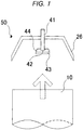
- FIG. 1 is a schematic cross-sectional view of an embodiment of liquid film dust arrester according to the present invention, illustrating the configuration thereof.
- liquid film dust arrester 50 is arranged to face a gas flow flowing out from a gas discharge pipe 10 to take the dust contained in the gas flow into liquid film and remove the dust from the gas flow.
- liquid film dust arresters 50 of an embodiment of flue gas desulfurization system are arranged vis-à-vis the gas discharge pipe 10 having a top opening for producing a gas flow that rise vertically upward
- the present invention is by no means limited to such an arrangement.
- one or more liquid film dust arresters may be arranged so as to face the corresponding respective gas flows that are not flowing out vertically upward, although one or more liquid film dust arresters are preferably arranged so as to face the corresponding respective gas flows that are flowing out vertically upward or downward.
- the liquid film dust arrester 50 of this embodiment comprises a gas flow blocking plate 26 that is a gas flow blocking unit arranged vis-à-vis an updraft (gas outflow) and a liquid film forming unit 40 for forming liquid film in the flow path of the updraft that is produced between the gas flow blocking plate 26 and a gas discharge pipe 10.
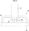
- the liquid film forming unit 40 in turn comprises, as shown in FIG. 2 , a liquid dispersion plate 43 (liquid dispersion unit) having a dispersion section 43a and a liquid lead-in pipe 41 (liquid ejection unit) having an ejection port 42 arranged vis-à-vis the dispersion section 43a to eject cleansing solution L 2 from the ejection port 42.
- the liquid dispersion plate 43 is arranged vis-à-vis the gas flow blocking plate 26 near the center of the gas flow blocking plate 26 and at an upstream position relative to the gas flow blocking plate 26 as viewed in the flowing direction of the updraft.
- the gas flow blocking plate 26 of this embodiment shows an inverted dish-like profile and receives the gas flow rising up from the gas discharge pipe 10 at the lower surface (inner surface) thereof.
- the gas flow contains liquid droplets, the liquid droplets stick to the lower surface of the gas flow blocking plate 26 to produce liquid film there at this time.
- gas flow blocking plate 26 also receives, at the lower surface thereof, part of the cleansing solution L 2 that is dispersed by the liquid lead-in pipe 41, which will be described in greater detail hereinafter, and the liquid dispersion plate 43, and flows down part of the cleansing solution L 2 from the front edge thereof.
- the gas flow blocking plate 26 may show an inverted dish-like profile as shown in FIG. 1 . Then, a center part of the gas flow blocking plate 26 operates as gas flow blocking surface area for receiving a gas flow and a liquid flow-down wall surface area is formed along the peripheral edge of the gas flow blocking surface area. The liquid flow-down wall surface area may receive part of the cleansing solution L 2 heading for the gas flow blocking plate 26 and colliding with it and allow the part of the cleansing solution L 2 to flow down from the front edge thereof.
- the gas flow blocking plate 26 may show an umbrella-like profile, where the gas flow blocking plate 26 has a single surface area as a whole that operates as gas flow blocking surface area and also as liquid flow-down surface area.
- the profile of the liquid flow-down wall surface area is not subject to any particular limitations. More specifically, the liquid flow-down wall surface area is only required to flow part of the cleansing solution L 2 that collides with the gas flow blocking plate 26 to flow down along its surface and drop down from its front edge.
- the liquid flow-down wall surface area may be a flat surface area, a curved surface area, a concave surface area, a convex surface area or a surface area showing some other profile.
- the liquid flow-down wall surface area is a smooth surface area.
- the profile of the gas flow blocking surface area that is surrounded along its periphery by the liquid flow-down wall surface area is not subject to any particular limitations so long as it can receive an updraft and produce a liquid flow directed toward the liquid flow-down wall surface area out of the liquid that collides with it.
- it may be a flat surface area, a curved surface area, a concave surface area, a convex surface area or a surface area showing some other profile.
- the gas flow blocking plate 26 has a single surface area as a whole that operates both as gas flow blocking surface area and as liquid flow-down wall surface area, its profile is not subject to any particular limitations.
- the single surface area may be a flat surface area, a curved surface area, a concave surface area, a convex surface area or a surface area showing some other profile.
- the single surface area is a smooth surface area.
- FIG. 2 is a schematic cross-sectional view of the liquid film forming unit 40, illustrating the configuration thereof.
- FIG. 2 is an enlarged schematic partial view of FIG. 1 .
- the liquid film forming unit 40 of this embodiment comprises a liquid dispersion plate 43, a liquid lead-in pipe 41 and a support section 44.
- FIG. 3 is a schematic top view of the liquid film forming unit 40 comprising the liquid dispersion plate 43, the liquid lead-in pipe 41 and the support section 44, illustrating the configurations thereof.
- FIG. 2 is a cross-sectional view of the liquid dispersion plate 43 taken along line (broken line) II-II in FIG. 3 , illustrating the configuration thereof.
- Cleansing solution L 2 is ejected from the liquid lead-in pipe 41, which is the liquid ejection unit, and the ejected liquid L 2 is dispersed by the liquid dispersion plate 43, which is the liquid dispersion unit.
- cleansing solution L 2 is preferably dispersed in a direction that is n-fold symmetric (where n is an integer not smaller than 2) relative to the direction of ejection of cleansing solution L 2 .
- cleansing solution L 2 is ejected substantially uniformly in all directions of 360o from the point of ejection in a plane perpendicular to the direction of ejection of cleansing solution L 2 .
- Any liquid can be used as liquid (cleansing solution L 2 ) to be ejected from the liquid ejection unit. More specifically, any liquid such as water, including sea water that is easily available can be used as liquid to be ejected from the liquid ejection unit. Particularly, the use of water is preferable because no dust is produced if water droplets are left in the treated gas flow.
- the liquid lead-in pipe 41 is arranged at the center part of the gas flow blocking plate 26 and runs through the center part of the gas flow blocking plate 26 in the vertical direction. Cleansing solution L 2 is fed into the liquid lead-in pipe 41 and ejected from the ejection port 42 of the liquid lead-in pipe 41 toward the liquid dispersion plate 43.
- the ejection port 42 is arranged at a front end of the liquid lead-in pipe 41 so as to face downward.
- cleansing solution L 2 is fed to the ejection port 42 by way of the liquid lead-in pipe 41 and ejected vertically downward from the ejection port 42.
- the liquid lead-in pipe 41 is hollow in the inside and may be so arranged as to eject cleansing solution L 2 directly from the front end thereof.
- the liquid lead-in pipe 41 may be provided at the front end thereof with a spray nozzle so as to eject (spray and disperse) cleansing solution L 2 by means of the spray nozzle.
- the aperture diameter of the ejection port 42 is preferably not smaller than 5 mm and not greater than 20 mm.
- the ejection velocity of cleansing solution L 2 can easily be controlled within a predetermined range when the aperture diameter is within the above-described range.
- the ejection velocity of cleansing solution L 2 is preferably not lower than 0.5 m/s and not higher than 3.0 m/s. Clogging of the ejection port 42 can be prevented from taking place when the ejection velocity of cleansing solution L 2 is within the above-described range.
- the ejection port 42 is arranged vis-à-vis the top surface of the liquid dispersion plate 43 and cleansing solution L 2 is ejected downward from the ejection port 42 in this embodiment, the ejection port 42 may alternatively be arranged vis-à-vis the bottom surface of the liquid dispersion plate 43 and cleansing solution L 2 may be ejected upward from the ejection port 42.
- the positional relationship of the ejection port 42 relative to the liquid dispersion plate 43 shown FIG. 2 may be turned upside down.
- liquid lead-in pipe 41 runs through the gas flow blocking plate 26 and extends to a neighboring area of the liquid dispersion plate 43 in this embodiment
- the present invention is by no means limited to such a positional arrangement.
- the liquid lead-in pipe 41 may alternatively be made to get into the liquid film dust arrester 50 from a lateral side of the liquid film dust arrester 50 (between the gas flow blocking plate 26 and the gas discharge pipe 10) and extend to a neighboring area of the liquid dispersion plate 43.
- the liquid dispersion plate 43 is arranged so as to face the center and its neighboring area of the gas flow blocking plate 26. Furthermore, the liquid dispersion plate 43 is arranged to face the updraft coming up toward it. In other words, the liquid dispersion plate 43 is arranged at the upstream side of the updraft relative to the gas flow blocking plate 26. Namely, as shown in FIG. 1 , the gas flow blocking plate 26 and the liquid dispersion plate 43 are arranged such that the top surface of the liquid dispersion plate 43 squarely faces the bottom surface of the gas flow blocking plate 26. Additionally, the liquid dispersion plate 43 is arranged such that it squarely faces the ejection port 42 of the liquid lead-in pipe 41 that projects downward from the center part of the gas flow blocking plate 26.
- the material to be used for forming the liquid dispersion plate 43 is not subject to any particular limitations. However, the use of an abrasion-resistant and corrosion-resistant material is preferable when solid-containing water is ejected as cleansing solution L 2 and the solid contained in the ejected water is typically dust and/or gypsum.
- abrasion-resistant and corrosion-resistant materials that can be used for the liquid dispersion plate 43 include metals such as stainless steel and thermoplastic materials such as polypropylene and polyvinylchloride and particularly preferable materials include SUS836L and NAS254N.
- the liquid dispersion plate 43 has a dispersion section 43a that is disposed vis-à-vis the ejection port 42 and the dispersion section 43a has a smooth surface.
- the dispersion section 43a is the part of the liquid dispersion plate 43 that the cleansing solution L 2 ejected from the ejection port 42 collides with. Additionally, the cleansing solution L 2 ejected from the ejection port 42 flows on the dispersion section 43a and becomes dispersed. In other words, the dispersion section 43a operates both as cleansing solution L 2 impinging surface and as surface for flowing and dispersing cleansing solution L 2 .
- the liquid dispersion plate 43 is disk-shaped and its top surface that operates as dispersion section 43a is a circular flat surface. Note, however, that the liquid dispersion plate 43 and the disperse section 43a of a liquid film dust arrester according to the present invention is by no means limited to the above-described ones.
- the dispersion section 43a may show any profile so long as it has a smooth surface and does not prevent cleansing solution L 2 from flowing smoothly.
- a dispersion section 43a having a smooth surface allows to form uniform liquid film and is not required to show a complex profile unlike any comparable conventional dispersion section 43a. Therefore, such a dispersion section 43a can advantageously be prepared with ease at low cost.
- a surface where grooves are formed, a plate-like profile having protrusions thereon (as disclosed in Japanese Patent No. 3,621,159 ) and a non-smooth surface such as a pyramidal surface having ridge lines are not within the scope of the present invention.
- the dispersion section 43a has a surface where grooves are formed, a plate-like profile having protrusions thereon or a non-smooth surface having ridge lines, areas where liquid densely flows and areas where liquid scarcely flows may arise on the non-smooth surface. Then, dispersion will become non-uniform on the dispersion section 43a and the dispersion section 43a will not be able to produce any uniform liquid film.
- the cleansing solution L 2 being employed in a liquid film dust arrester that is arranged in a flue gas desulfurization system contains dust and/or gypsum and the dispersion section 43a has a non-smooth surface
- abrasion-induced local degradation occurs to the dispersion section 43a due to uneven liquid flows and dust and/or gypsum can locally stop moving and stick to the dispersion section 43a.
- the dispersion section 43a has a flat surface or a smooth convex surface that is upwardly curved toward the ejection port 42.
- cleansing solution L 2 does not give rise to any slow flow and smoothly flows on the dispersion section 43a so that any component hardly sticks to the dispersion section 43a to make the servicing operation an easy one or unnecessary.
- Example of profiles that the liquid dispersion plate 43 having the dispersion section 43a preferably shows include a disk-shaped profile, a cone-shaped (conical) profile, an inverted dish-shaped profile and a profile of part of a sphere (a profile obtained by cutting a sphere with a plane) such as a semispherical profile.
- the top surface of a liquid dispersion plate 43 having such a profile operates as dispersion section 43a.
- a part having a profile that does not interfere with the flow of cleansing solution L 2 may be annexed to such a profile.
- a hat-like profile formed by a semispherical profile to the peripheral edge of which a hat rim-like profile is annexed may be an example of such a profile.
- the liquid dispersion plate 43 When the liquid dispersion plate 43 has a convex surface that is upwardly curved, it may be formed by using a plate-like member (for example, a hollow cone having no bottom) or a member having an upwardly curved profile and a solid inside (for example, a solid cone).
- a plate-like member for example, a hollow cone having no bottom
- a member having an upwardly curved profile and a solid inside for example, a solid cone
- the dispersion section 43a is preferably n-fold symmetrical relative to the direction of ejection of cleansing solution L 2 of the ejection port 42, where n is an integer not smaller than 2.
- n is an integer not smaller than 2.
- the cleansing solution L 2 that is dispersed on the dispersion section 43a becomes symmetrical relative to any surface direction and advantageously highly uniformly flows on the surface of the dispersion section 43a.
- cleansing solution L 2 is advantageously dispersed substantially uniformly in all directions of 360o.
- cleansing solution L 2 is ejected from the ejection port 42 vertically downwardly and the dispersion section 43a is arranged horizontally.
- cleansing solution L 2 is dispersed substantially symmetrically in all direction of 360o from the point of ejection to produce uniform liquid film.
- liquid dispersion plate 43 is supported by three support sections 44 that are arranged angularly at regular intervals.
- support sections 44 are not subject to any particular limitations and any appropriate number and profile of support sections may be used for the purpose of the present invention. Additionally, the support sections 44 may be bonded to the liquid lead-in pipe 41 or, alternatively, they may be bonded to a member other than the liquid lead-in pipe 41.
- Cleansing solution L 2 is ejected from the ejection port 42 of the liquid lead-in pipe 41 that is located at or near the center of the dispersion section 43a of the liquid dispersion plate 43.
- the ejected cleansing solution L 2 spreads substantially uniformly from the center part toward the peripheral part of the dispersion section 43a and flows out from the liquid dispersion plate 43.
- the cleansing solution L 2 that flows out then scatters toward the inner wall of the gas discharge pipe 10, between the gas discharge pipe 10 and the gas flow blocking plate 26 and toward the bottom surface (inner surface) of the gas flow blocking plate 26.
- liquid film As used for the purpose of the present invention is not limited to continuous liquid film but may take any other form so long as it allows gas-liquid contact to take place to a satisfactory extent between the formed liquid film and the gas flowing there.
- liquid film may be in the form of discontinuous liquid droplets, in the form of mist or in the form of a multiple of liquid flow.
- the part of the cleansing solution L 2 that scatters toward the bottom surface of the gas flow blocking plate 26 collides with the bottom surface thereof and then flows down from the front edge of the gas flow blocking plate 26.
- the part of the cleansing solution L 2 that scatters toward the inner wall of the gas discharge pipe 10 collides with the inner wall and then flows down.
- the part of the cleansing solution L 2 that scatters toward the inner wall of the gas discharge pipe 10 the part of the cleansing solution L 2 that scatters toward the bottom surface of the gas flow blocking plate 26 and the part of the cleansing solution L 2 that flows down from the gas flow blocking plate 26 also contact the updraft to take part in the operation of taking in and removing the dust contained in the updraft.
- the cleansing solution L 2 that is ejected from the ejection port 42 contacts practically only the dispersion section 43a of the liquid dispersion plate 43 and flows out toward between the gas discharge pipe 10 and the gas flow blocking plate 26 and in some other directions. Therefore, in this embodiment, the ejected cleansing solution L 2 practically contacts only the top surface of the liquid dispersion plate 43 and hence the top surface of the liquid dispersion plate 43 where cleansing solution L 2 contacts is referred to as dispersion section 43a.
- dispersion section 43a On the other hand, in this embodiment, only a small part of the cleansing solution L 2 that is ejected from the ejection port 42 may become droplets and fall down along the lateral surface of the liquid dispersion plate 43. However, such contact does not give rise to any dispersion of cleansing solution L 2 and hence the lateral surface of the liquid dispersion plate 43 does not belong to the dispersion section 43a.
- the updraft (including the gas flow produced after the updraft collides with the gas flow blocking plate 26) passes between the gas discharge pipe 10 and the gas flow blocking plate 26 without fail.
- the updraft moving up from the gas discharge pipe 10 directly flows into the flow path formed between the gas discharge pipe 10 and the gas flow blocking plate 26 or collides with the bottom surface of the gas flow blocking plate 26 and then is guided by the bottom surface of the gas flow blocking plate 26 to change its flow direction and flows into the flow path formed between the gas flow blocking plate 26 and the gas discharge pipe 10.
- liquid film is formed in the flow path of the updraft produced between the gas discharge pipe 10 and the gas flow blocking plate 26.
- the liquid film is formed vis-à-vis the updraft that flows through the flow path produced between the gas discharge pipe 10 and the gas flow blocking plate 26. Then, the dust contained in the updraft is taken into the liquid film and removed as the updraft flows through the flow path.
- the ratio of the area S1 of the aperture of the ejection port 42 to the area S2 of the dispersion section 43a that is a smooth surface (and hence the region where cleansing solution L 2 contacts), or S1/S2, is preferably not smaller than 0.001 and not greater than 0.06, more preferably not smaller than 0.003 and not greater than 0.04.
- the distance separating the ejection port 42 and the dispersion section 43a is preferably not less than 3 mm and not more than 50 mm, more preferably not less than 5 mm and not more than 30 mm.
- the ejection port 42 can effectively be prevented from being clogged when the distance between the ejection port 42 and the dispersion section 43a is within the above range.
- the flow rate of cleansing solution L 2 ejected from the ejection port 42 is normally not smaller than 0.1 kg/hr and not greater than 10 kg/hr, preferably not smaller than 0.2 kg/hr and not greater than 2 kg/hr, based on 1 m 3 /hr of gas as reduced to the standard condition of moving up from the gas discharge pipe 10.
- the dust contained in the gas moving up from the gas discharge pipe 10 can effectively be removed when cleansing solution L 2 at any of the foregoing flow rates is ejected at the above defined flow rate and dispersed to form liquid film.
- a liquid film dust arrester according to the present invention can be used for any application provided that a sufficient area is secured to install the liquid film dust arrester, although it may typically be installed in a flue gas desulfurization system.
- a flue gas desulfurization system according to the present invention comprises one or more liquid film dust arresters according to the present invention as described above.
- flue gas desulfurization system that will be described below is a wet flue gas desulfurization system, which is also referred to as jet bubbling reactor (JBR) type flue gas desulfurization system, that desulfurizes sulfur oxides-containing combustion exhaust flue gas (gas to be treated) by means of gas-phase dispersion type gas-liquid contacting devices and an absorber solution containing an alkali agent.
- JBR jet bubbling reactor
- absorber solution for removing sulfur oxides is contained in a bottom part of a sealed vessel, which is a reaction vessel, and flue gas and air (oxygen) are introduced into the absorber solution to cause gas-liquid contact of the sulfur oxides in flue gas and the liquid alkali agent in the absorber solution to take place in the presence of oxygen and make them react with each other, while forming a jet bubbling layer (froth layer).
- flue gas and air oxygen
- Sulfur oxides (SOx) to be treated by this embodiment typically include sulfur dioxide.
- Sulfur dioxide is produced in many different ways. For example, sulfur dioxide is produced particularly when sulfurous gas is dissolved in water.
- Sulfur oxides-containing combustion exhaust flue gas exhaust gas is typically emitted from furnaces and power generation plants where coal is burnt.
- sulfur oxides such as SO 2 contained in flue gas is made to react with an alkali agent and oxygen, hardly soluble solids are produced and sulfur oxides are removed from the flue gas.
- sulfur oxides contained in flue gas include SO 2 and limestone (CaCO 3 ) is employed as alkali agent for desulfurization
- a reaction expressed by formula (1) shown below takes place to produce gypsum (CaSO 4 ⁇ 2H 2 O) so that SO 2 can be removed from flue gas.
- flue gas contains not only sulfur oxides but also soot and dust.
- soot and dust contained in flue gas to be treated are also removed as flue gas and absorber solution are brought into gas-liquid contact in the froth layer of the flue gas desulfurization system. More specifically, the soot and dust contained in flue gas is removed as flue gas and the cleansing solution are brought into gas-liquid contact at the liquid film dust arresters that the flue gas desulfurization system comprises.
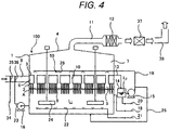
- FIG. 1 is a schematic cross-sectional view of an embodiment of flue gas desulfurization system according to the present invention, illustrating the configuration thereof.
- the entire flue gas desulfurization system 100 of this embodiment is contained in a large-size sealed vessel 1, in which sulfur oxides and dust are removed from flue gas that contains sulfur oxides and dust.
- the inside of the sealed vessel 1 is partitioned into a first chamber 5, a second chamber 6 which is located adjacent to and above the first chamber 5 and a third chamber 7 which is located adjacent to and above the second chamber 6 by first partition board 2 and second partition board 3 which is located above the first partition board 2.
- the upper space of the third chamber 7 is sealed by a ceiling plate 4.
- the first partition board 2 is a substantially horizontal board.
- the second partition board 3 is also a substantially horizontal board.
- the peripheral wall of the second chamber 6 is provided with a flue gas inlet.
- a flue gas lead-in duct 8 is coupled to the flue gas inlet.
- Absorber solution L 1 is drawn out from the first chamber 5 by means of a circulation pump 16 and fed into the absorber solution extraction pipe 23.
- industrial water that is supplied from an industrial water source (not shown) is sprayed into the flue gas lead-in duct 8 from industrial water nozzle 35 by way of industrial water pipe 34.
- a flue gas cooling device is coupled to the flue gas inlet arranged at the peripheral wall of the sealed vessel 1 and the flue gas that is cooled by the flue gas cooling device (and additionally subjected to a dust removal operation and a desulfurization operation to some extent) is led into the sealed vessel 1 by way of the flue gas inlet.
- the flue gas cooling device comprises the flue gas lead-in duct 8, the circulation pump 16, the industrial water pipe 34, the industrial water nozzle 35, the absorber solution extraction pipe 23 and the absorber solution nozzle 36, although the makeup of the flue gas cooling device is not limited to the above-described one.
- the makeup of the flue gas cooling device is not subject to any particular limitations so long as it is so arranged as to be able to cool the flue gas that is led into it.
- the flue gas cooling device may comprise only either the industrial water nozzle 35 or the absorber solution nozzle 36 and may additionally comprise some other cooling mechanism.
- a spray nozzle (not shown) for spraying absorber solution L 1 may be installed in the space.
- absorber solution L 1 When absorber solution L 1 is to be sprayed into the space of the second chamber 6, absorber solution L 1 contained in the first chamber 5 can be fed into the second chamber 6 by branching the absorber solution extraction pipe 23.
- the first partition board 2 is provided with a large number of through holes that allow the first chamber 5 and the second chamber 6 to communicate with each other.
- a large number of flue gas dispersion pipes 9 extend downward from the respective through holes in order to cause the flue gas fed into the second chamber 6 to disperse in the absorber solution L 1 contained in the first chamber 5. More specifically, the flue gas dispersion pipes 9 are arranged to extend downward from the respective through holes so as to make the front tips of the flue gas dispersion pipes 9 dip into the absorber solution L 1 contained in the first chamber 5. Thus, the flue gas that is led into the second chamber 6 is then blown into the absorber solution L 1 contained in the first chamber 5 by way of the flue gas dispersion pipes 9.
- Each of the flue gas dispersion pipes 9 is provided at the peripheral wall thereof with one or more than one dispersion hole for discharging flue gas, which one or more than one dispersion holes are arranged in the region of the pipe located below the surface level of the absorber solution L 1 in the first chamber 5.
- each of the flue gas dispersion pipes 9 is provided with a plurality of dispersion holes.
- the profile and the positional arrangement of the dispersion holes are not subject to any particular limitations so long as they can effectively and excellently disperse flue gas in the absorber solution L 1 contained in the first chamber 5.
- An exemplar arrangement may be such that the dispersion holes of each of the flue gas dispersion pipes 9, which are cylindrical pipes, show a circular cross section and are arranged at positions separated from the bottom ends of the flue gas dispersion pipes 9 by a predetermined distance in the direction perpendicular to the extending direction of the dispersion pipe 9, any two adjacently located dispersion holes of each of the flue gas dispersion pipes 9 being separated by an angle of 30o as viewed from the central axis of the flue gas dispersion pipe 9 (so that a total of 12 dispersion holes are arranged at angularly regular intervals in the direction perpendicular to the extending direction of the flue gas dispersion pipe 9).
- Absorber solution L 1 is contained in the first chamber 5. Absorber solution L 1 is fed into the first chamber 5 by way of absorber solution feed pipe 18.
- Absorber solution L 1 of this embodiment contains an alkali agent.
- the alkali agent contained in absorber solution L 1 is a neutralizer agent for neutralizing acid.
- neutralizer agents include calcium carbonate (limestone) and sodium hydroxide.
- the solvent to be used for alkali agent-containing absorber solution L 1 that can be used for this embodiment may typically be water.
- absorber solution L 1 is not subject to any particular limitations so long as it can absorb sulfur oxides.
- Stirrers 24 and oxygen-containing gas spouting jet nozzles 22 to be used, whenever necessary, for supplying oxygen into the absorber solution L 1 in the first chamber 5 are arranged in the first chamber 5.
- the oxygen-containing gas spouting jet nozzles 22 supply air (oxygen) to the alkali agent-containing absorber solution L 1 and also to the flue gas in the first chamber 5. Air is supplied to the oxygen-containing gas spouting jet nozzles 22 from a feed blower (not shown) by way of an oxygen-containing gas feed pipe 21. It is sufficient for the oxygen-containing gas spouting jet nozzles 22 that they can only supply oxygen-containing gas (gas for oxidation) and not air but only oxygen or any gas other than air that contains oxygen may alternatively be supplied to the jet nozzles 22.
- flue gas is blown into the absorber solution L 1 from the second chamber 6 by way of the flue gas dispersion pipes 9.
- the flue gas that is blown into the absorber solution L 1 then moves upward in the absorber solution L 1 contained in the first chamber 5 as bubbles.
- a froth layer A in a mixed phase of bubbles and absorber solution L 1 is formed immediately above the level of the dispersion holes of the flue gas dispersion pipes 9 in the first chamber 5. While flue gas moves up in the absorber solution L 1 as bubbles and while flue gas stays in the froth layer A as bubbles, the dust and the sulfur oxides contained in the flue gas are seized in the absorber solution L 1 and then removed from the flue gas.
- the flue gas that is cleansed (desulfurized) in the above-described manner is then allowed to move upward from the froth layer A and dissipate in the upper space. Thereafter, it is led into the third chamber 7 by way of gas discharge pipes 10, which will be described in greater detail hereinafter.
- the first partition board 2 and the second partition board 3 are provided with a same number of apertures.
- the apertures of the first partition board 2 are arranged squarely vis-à-vis the corresponding respective apertures of the second partition boards 3 to form so many aperture pairs.
- a gas discharge pipe 10 is arranged to connect each of the aperture pairs so as to close the inner space of the second chamber 6 and hold the first chamber 5 and the third chamber 7 in communication with each other.
- the gas discharge pipes 10 allow the desulfurized flue gas staying in the upper space of the first chamber 5 to be led into the third chamber 7.
- the upper ends of the gas discharge pipes 10 project upward from the top surface of the second partition board 3 that surrounds them so as to make a predetermined amount of cleansing solution L 2 stay on the second partition board 3.
- the horizontal cross section of each of the gas discharge pipes 10 may be of any shape such as circular, square or rectangular.
- a plurality of liquid film dust arresters 50 according to the present invention are arranged in the third chamber 7 respectively above the outlets of the corresponding gas discharge pipes 10.
- the ceiling board 4 arranged at the top of the third chamber 7 is provided with a desulfurized flue gas outlet and a desulfurized flue gas lead-out duct 11 is coupled to the desulfurized flue gas outlet.
- the desulfurized flue gas outlet may alternatively be arranged at the peripheral wall of the third chamber 7.
- Liquid film of cleansing solution L 2 is formed in the flow path between the gas discharge pipes 10 and the gas flow blocking plates 26 that the liquid film dust arresters 50 have by the liquid film dust arresters 50 that are arranged in the third chamber 7 squarely above the respective corresponding gas discharge pipes 10.
- the flue gas discharged from the gas discharge pipes 10 passes through the liquid film of cleansing solution L 2 .
- the flue gas contacts the liquid film of gas cleansing solution L 2 and the dust remaining in the flue gas is seized by the liquid film and removed from the flue gas.
- the desulfurized flue gas in the third chamber 7 is drawn out to the outside of the third chamber 7 (of the sealed vessel 1) by way of desulfurized flue gas lead-out duct 11. Thereafter, the flue gas drawn out from the third chamber 7 is led into mist eliminator 12, in which mist eliminator 12 the absorber solution Li, the particles in the absorber solution L 2 and other components that are contained in the flue gas are further removed. Then, the desulfurized flue gas discharged from the mist eliminator 12 gets into heater 37, in which heater 37 the mist remaining in the desulfurized flue gas is gasified and then discharged into the atmosphere by way of flue gas chimney 38.
- a circulation line for causing the cleansing solution L 2 staying on the second partition board 3 that operates as the bottom surface of the third chamber 7 to circulate into the liquid film dust arresters 50 in the third chamber 7 is arranged outside the sealed vessel 1.
- the circulation line comprises cleansing solution discharge pipe 13 for drawing out the cleansing solution L 2 fed onto the second partition board 3, cleansing solution tank 14 for storing the drawn-out cleansing solution L 2 , circulation pump 15 for circulating the cleansing solution L 2 from the cleansing solution tank 14 and cleansing solution feed pipe 19 coupled to the circulation pump 15 to feed the cleansing solution L 2 into the third chamber 7 (liquid lead-in pipes 41).
- the cleansing solution tank 14 is coupled to cleansing solution replenishing pipe 20 for replenishing cleansing solution so that cleansing solution is replenished by way of the cleansing solution replenishing pipe 20.
- part of the cleansing solution L 2 that is circulated into the liquid film dust arresters 50 is led into the absorber solution L 1 by way of conduit 25 branched from the cleansing solution feed pipe 19.
- the component composition of the cleansing solution L 2 circulating into the liquid film dust arresters 50 can be held within a predetermined range and hence the solid component removing capability of the cleansing solution L 2 can be maintained at a high level.
- the cleansing solution tank 14 operates as storage tank for temporarily storing the cleansing solution L 2 staying on the top surface of the second partition board 3 that operates as the floor surface of the third chamber 7 and at the same time for receiving and storing the cleansing solution for replenishment.
- the installation of the cleansing solution tank 14 is not indispensably required.
- the cleansing solution tank 14 may be omitted and the cleansing solution discharge pipe 13 may be directly coupled to the circulation pump 15.
- the cleansing solution replenishing pipe 20 is coupled to the cleansing solution discharge pipe 13 or the cleansing solution feed pipe 19 so as to directly supply the cleansing solution for replenishment.
- liquid film dust arrester 50 and that of flue gas desulfurization system 100 can form substantially uniform liquid film and achieve a high dust removing performance, although they require neither complex processing steps for preparing the liquid dispersion plate 43 nor additional dust removing equipment and hence can be provided at low cost. Additionally, the described embodiment of liquid film dust arrester 50 and that of flue gas desulfurization system 100 are practically free from degradation and solid adhesion due to local wear even when they are operated to eject cleansing solution L 2 that contains solids (gypsum and dust) to produce liquid film because the dispersion section 43a of the liquid dispersion plate 43 is a smooth surface. Thus, they provide an advantage of excellent durability and easy servicing.
Landscapes
- Chemical & Material Sciences (AREA)
- Engineering & Computer Science (AREA)
- Chemical Kinetics & Catalysis (AREA)
- Environmental & Geological Engineering (AREA)
- Oil, Petroleum & Natural Gas (AREA)
- Analytical Chemistry (AREA)
- General Chemical & Material Sciences (AREA)
- Biomedical Technology (AREA)
- Health & Medical Sciences (AREA)
- Mechanical Engineering (AREA)
- General Engineering & Computer Science (AREA)
- Treating Waste Gases (AREA)
- Gas Separation By Absorption (AREA)
- Separation Of Particles Using Liquids (AREA)
Applications Claiming Priority (2)
| Application Number | Priority Date | Filing Date | Title |
|---|---|---|---|
| JP2015238296A JP6730024B2 (ja) | 2015-12-07 | 2015-12-07 | 液幕除塵装置および排煙脱硫装置 |
| PCT/JP2016/004999 WO2017098698A1 (ja) | 2015-12-07 | 2016-11-29 | 液幕除塵装置および排煙脱硫装置 |
Publications (2)
| Publication Number | Publication Date |
|---|---|
| EP3388134A1 true EP3388134A1 (de) | 2018-10-17 |
| EP3388134A4 EP3388134A4 (de) | 2019-07-31 |
Family
ID=59012905
Family Applications (1)
| Application Number | Title | Priority Date | Filing Date |
|---|---|---|---|
| EP16872600.8A Withdrawn EP3388134A4 (de) | 2015-12-07 | 2016-11-29 | Flüssigkeitsvorhangentstaubungsvorrichtung und rauchgasentschwefelungsvorrichtung |
Country Status (8)
| Country | Link |
|---|---|
| US (1) | US10780386B2 (de) |
| EP (1) | EP3388134A4 (de) |
| JP (1) | JP6730024B2 (de) |
| KR (1) | KR20180090349A (de) |
| CN (1) | CN108367227A (de) |
| CA (1) | CA3005958A1 (de) |
| TW (1) | TW201733657A (de) |
| WO (1) | WO2017098698A1 (de) |
Cited By (1)
| Publication number | Priority date | Publication date | Assignee | Title |
|---|---|---|---|---|
| CN112090202A (zh) * | 2020-09-28 | 2020-12-18 | 滁州市汊河之星高新技术研发有限公司 | 一种环保工程用有害气体处理装置 |
Families Citing this family (8)
| Publication number | Priority date | Publication date | Assignee | Title |
|---|---|---|---|---|
| WO2019061097A1 (zh) * | 2017-09-27 | 2019-04-04 | 北京中能诺泰节能环保技术有限责任公司 | 除尘除雾装置及吸收塔 |
| CN110721588A (zh) * | 2019-10-29 | 2020-01-24 | 上海蓝魂环保科技有限公司 | 一种具有除尘作用的船舶海水脱硫设备 |
| CN115379886A (zh) * | 2020-02-14 | 2022-11-22 | 洁净空气地带股份有限公司 | 空气净化机及过程 |
| CN113385009B (zh) * | 2021-05-18 | 2024-02-02 | 朝阳市宏晟机械制造有限公司 | 一种燃烧烟气脱硫脱硝塔 |
| IT202100015047A1 (it) * | 2021-06-09 | 2022-12-09 | Solidea S R L | Dispositivo filtrante per canne fumarie |
| CN116212550B (zh) * | 2023-03-22 | 2024-04-02 | 华中科技大学 | 基于复合吸收液的分级湿法烟气超净脱硫脱硝除尘装置 |
| CN117085437B (zh) * | 2023-09-05 | 2025-09-09 | 北新集团建材股份有限公司 | 一种烟道内上喷淋式降尘装置 |
| CN117923583B (zh) * | 2023-12-29 | 2025-10-31 | 青岛润扬环境科技有限公司 | 一种脱硫废水低温烟气蒸发结晶系统 |
Family Cites Families (12)
| Publication number | Priority date | Publication date | Assignee | Title |
|---|---|---|---|---|
| JPS467688Y1 (de) * | 1966-06-07 | 1971-03-18 | ||
| JPS5225477A (en) * | 1975-08-20 | 1977-02-25 | Masamoto Kaneko | Incinerator |
| JPS621159A (ja) | 1985-06-27 | 1987-01-07 | Canon Inc | 記録又は再生装置 |
| DE4300751C2 (de) * | 1993-01-14 | 1994-10-27 | Bernhard Reintanz | Vorrichtung zum Versprühen von Flüssigkeit, insbesondere von einer Kalkmilchsuspension in Rauchgase von Rauchgas-Entschwefelungsanlagen von Kraftwerken und Müllverbrennungsanlagen von Kraftwerken und Müllverbrennungsanlagen |
| JP3621159B2 (ja) * | 1995-06-20 | 2005-02-16 | 千代田化工建設株式会社 | 排ガスの処理方法及び装置 |
| US5741340A (en) * | 1995-08-18 | 1998-04-21 | Klemmer; Roland | Air venting unit |
| JP4343412B2 (ja) * | 2000-08-30 | 2009-10-14 | 東洋エンジニアリング株式会社 | 電気集塵機 |
| JP4114852B2 (ja) * | 2001-08-22 | 2008-07-09 | 金子農機株式会社 | 穀物乾燥機用集塵装置 |
| KR200359932Y1 (ko) | 2004-04-17 | 2004-08-27 | 채원수 | 고기구이기의 대기오염방지 장치 |
| JP2008296152A (ja) * | 2007-05-31 | 2008-12-11 | Okawara Mfg Co Ltd | スクラバ装置 |
| JP5660771B2 (ja) * | 2009-10-26 | 2015-01-28 | 千代田化工建設株式会社 | 排ガス処理装置 |
| PL2463014T3 (pl) | 2010-12-10 | 2018-10-31 | General Electric Technology Gmbh | Płuczka wodna zawierająca płytki odchylające i sposób oczyszczania gazu technologicznego |
-
2015
- 2015-12-07 JP JP2015238296A patent/JP6730024B2/ja active Active
-
2016
- 2016-11-29 KR KR1020187019112A patent/KR20180090349A/ko not_active Ceased
- 2016-11-29 US US15/778,111 patent/US10780386B2/en active Active
- 2016-11-29 EP EP16872600.8A patent/EP3388134A4/de not_active Withdrawn
- 2016-11-29 CN CN201680071545.9A patent/CN108367227A/zh active Pending
- 2016-11-29 CA CA3005958A patent/CA3005958A1/en not_active Abandoned
- 2016-11-29 WO PCT/JP2016/004999 patent/WO2017098698A1/ja not_active Ceased
- 2016-12-06 TW TW105140263A patent/TW201733657A/zh unknown
Cited By (1)
| Publication number | Priority date | Publication date | Assignee | Title |
|---|---|---|---|---|
| CN112090202A (zh) * | 2020-09-28 | 2020-12-18 | 滁州市汊河之星高新技术研发有限公司 | 一种环保工程用有害气体处理装置 |
Also Published As
| Publication number | Publication date |
|---|---|
| JP2017104768A (ja) | 2017-06-15 |
| WO2017098698A1 (ja) | 2017-06-15 |
| CA3005958A1 (en) | 2017-06-15 |
| US10780386B2 (en) | 2020-09-22 |
| EP3388134A4 (de) | 2019-07-31 |
| US20180345202A1 (en) | 2018-12-06 |
| JP6730024B2 (ja) | 2020-07-29 |
| TW201733657A (zh) | 2017-10-01 |
| CN108367227A (zh) | 2018-08-03 |
| KR20180090349A (ko) | 2018-08-10 |
Similar Documents
| Publication | Publication Date | Title |
|---|---|---|
| US10780386B2 (en) | Liquid film dust arrester and flue gas desulfurization system | |
| US10661222B1 (en) | Flue gas desulfurization system | |
| US10143957B2 (en) | High-efficiency gradient hierarchy complex desulfurizing tower | |
| CA2137364C (en) | Wet-type flue gas desulfurization plant | |
| US9915423B2 (en) | Rotational flow and sink flow-coupling integrated system for ultra-clean desulphuration and dedusting and desulphuration and dedusting method therefor | |
| EP2463014B1 (de) | Nasswäscher mit Deflektorplatten, und Verfahren zur Reinigung eines Prozessgases | |
| CN103476478B (zh) | 用于清洁废气的湿式洗涤器 | |
| JP2023025270A (ja) | 排ガス処理方法および排ガス処理装置 | |
| JP6151980B2 (ja) | 粉体排出システム | |
| IL256002B (en) | A multi-stage gas scrubber is allowed to scrub flooded areas | |
| KR101278171B1 (ko) | 가스로부터 이산화황을 분리하기 위한 방법 및 장치 | |
| JP2006122862A (ja) | 排ガス処理装置 | |
| JP2003103139A (ja) | 湿式排煙脱硫装置 | |
| JPH10192647A (ja) | 湿式排煙脱硫装置 | |
| RU2724780C1 (ru) | Устройство для мокрой очистки газов | |
| US10843115B2 (en) | Method of removing impurities | |
| JPH09313877A (ja) | 排煙脱硫装置と方法 | |
| CN104368236A (zh) | 一种气液双向导流的烟气吸收塔 | |
| JP2002361036A (ja) | 吸収剤散布方法及び吸収剤散布ノズル | |
| JPWO1994023826A1 (ja) | 湿式排煙脱硫装置 |
Legal Events
| Date | Code | Title | Description |
|---|---|---|---|
| STAA | Information on the status of an ep patent application or granted ep patent |
Free format text: STATUS: THE INTERNATIONAL PUBLICATION HAS BEEN MADE |
|
| PUAI | Public reference made under article 153(3) epc to a published international application that has entered the european phase |
Free format text: ORIGINAL CODE: 0009012 |
|
| STAA | Information on the status of an ep patent application or granted ep patent |
Free format text: STATUS: REQUEST FOR EXAMINATION WAS MADE |
|
| 17P | Request for examination filed |
Effective date: 20180608 |
|
| AK | Designated contracting states |
Kind code of ref document: A1 Designated state(s): AL AT BE BG CH CY CZ DE DK EE ES FI FR GB GR HR HU IE IS IT LI LT LU LV MC MK MT NL NO PL PT RO RS SE SI SK SM TR |
|
| AX | Request for extension of the european patent |
Extension state: BA ME |
|
| DAV | Request for validation of the european patent (deleted) | ||
| DAX | Request for extension of the european patent (deleted) | ||
| A4 | Supplementary search report drawn up and despatched |
Effective date: 20190627 |
|
| RIC1 | Information provided on ipc code assigned before grant |
Ipc: B01D 53/50 20060101ALI20190621BHEP Ipc: B01D 53/78 20060101ALI20190621BHEP Ipc: B01D 47/06 20060101ALI20190621BHEP Ipc: B01D 45/10 20060101ALI20190621BHEP Ipc: F23J 15/04 20060101ALI20190621BHEP Ipc: B01D 47/02 20060101ALI20190621BHEP Ipc: B01D 47/00 20060101AFI20190621BHEP Ipc: B01D 53/75 20060101ALI20190621BHEP Ipc: B01D 53/18 20060101ALI20190621BHEP |
|
| GRAP | Despatch of communication of intention to grant a patent |
Free format text: ORIGINAL CODE: EPIDOSNIGR1 |
|
| STAA | Information on the status of an ep patent application or granted ep patent |
Free format text: STATUS: GRANT OF PATENT IS INTENDED |
|
| INTG | Intention to grant announced |
Effective date: 20200723 |
|
| STAA | Information on the status of an ep patent application or granted ep patent |
Free format text: STATUS: THE APPLICATION IS DEEMED TO BE WITHDRAWN |
|
| 18D | Application deemed to be withdrawn |
Effective date: 20201203 |