EP3386780B1 - Axle and suspension systems - Google Patents
Axle and suspension systems Download PDFInfo
- Publication number
- EP3386780B1 EP3386780B1 EP16825334.2A EP16825334A EP3386780B1 EP 3386780 B1 EP3386780 B1 EP 3386780B1 EP 16825334 A EP16825334 A EP 16825334A EP 3386780 B1 EP3386780 B1 EP 3386780B1
- Authority
- EP
- European Patent Office
- Prior art keywords
- axle
- bush
- mount
- frame
- suspension system
- Prior art date
- Legal status (The legal status is an assumption and is not a legal conclusion. Google has not performed a legal analysis and makes no representation as to the accuracy of the status listed.)
- Active
Links
Images


Classifications
-
- B—PERFORMING OPERATIONS; TRANSPORTING
- B60—VEHICLES IN GENERAL
- B60G—VEHICLE SUSPENSION ARRANGEMENTS
- B60G7/00—Pivoted suspension arms; Accessories thereof
- B60G7/02—Attaching arms to sprung part of vehicle
-
- B—PERFORMING OPERATIONS; TRANSPORTING
- B60—VEHICLES IN GENERAL
- B60G—VEHICLE SUSPENSION ARRANGEMENTS
- B60G9/00—Resilient suspensions of a rigid axle or axle housing for two or more wheels
- B60G9/02—Resilient suspensions of a rigid axle or axle housing for two or more wheels the axle or housing being pivotally mounted on the vehicle, e.g. the pivotal axis being parallel to the longitudinal axis of the vehicle
-
- B—PERFORMING OPERATIONS; TRANSPORTING
- B60—VEHICLES IN GENERAL
- B60B—VEHICLE WHEELS; CASTORS; AXLES FOR WHEELS OR CASTORS; INCREASING WHEEL ADHESION
- B60B35/00—Axle units; Parts thereof ; Arrangements for lubrication of axles
- B60B35/02—Dead axles, i.e. not transmitting torque
- B60B35/04—Dead axles, i.e. not transmitting torque straight
-
- B—PERFORMING OPERATIONS; TRANSPORTING
- B60—VEHICLES IN GENERAL
- B60G—VEHICLE SUSPENSION ARRANGEMENTS
- B60G11/00—Resilient suspensions characterised by arrangement, location or kind of springs
- B60G11/26—Resilient suspensions characterised by arrangement, location or kind of springs having fluid springs only, e.g. hydropneumatic springs
- B60G11/27—Resilient suspensions characterised by arrangement, location or kind of springs having fluid springs only, e.g. hydropneumatic springs wherein the fluid is a gas
-
- B—PERFORMING OPERATIONS; TRANSPORTING
- B60—VEHICLES IN GENERAL
- B60G—VEHICLE SUSPENSION ARRANGEMENTS
- B60G9/00—Resilient suspensions of a rigid axle or axle housing for two or more wheels
- B60G9/003—Resilient suspensions of a rigid axle or axle housing for two or more wheels the axle being rigidly connected to a trailing guiding device
-
- F—MECHANICAL ENGINEERING; LIGHTING; HEATING; WEAPONS; BLASTING
- F16—ENGINEERING ELEMENTS AND UNITS; GENERAL MEASURES FOR PRODUCING AND MAINTAINING EFFECTIVE FUNCTIONING OF MACHINES OR INSTALLATIONS; THERMAL INSULATION IN GENERAL
- F16F—SPRINGS; SHOCK-ABSORBERS; MEANS FOR DAMPING VIBRATION
- F16F1/00—Springs
- F16F1/36—Springs made of rubber or other material having high internal friction, e.g. thermoplastic elastomers
- F16F1/38—Springs made of rubber or other material having high internal friction, e.g. thermoplastic elastomers with a sleeve of elastic material between a rigid outer sleeve and a rigid inner sleeve or pin, i.e. bushing-type
- F16F1/3828—End stop features or buffering
-
- F—MECHANICAL ENGINEERING; LIGHTING; HEATING; WEAPONS; BLASTING
- F16—ENGINEERING ELEMENTS AND UNITS; GENERAL MEASURES FOR PRODUCING AND MAINTAINING EFFECTIVE FUNCTIONING OF MACHINES OR INSTALLATIONS; THERMAL INSULATION IN GENERAL
- F16F—SPRINGS; SHOCK-ABSORBERS; MEANS FOR DAMPING VIBRATION
- F16F1/00—Springs
- F16F1/36—Springs made of rubber or other material having high internal friction, e.g. thermoplastic elastomers
- F16F1/38—Springs made of rubber or other material having high internal friction, e.g. thermoplastic elastomers with a sleeve of elastic material between a rigid outer sleeve and a rigid inner sleeve or pin, i.e. bushing-type
- F16F1/3842—Method of assembly, production or treatment; Mounting thereof
-
- F—MECHANICAL ENGINEERING; LIGHTING; HEATING; WEAPONS; BLASTING
- F16—ENGINEERING ELEMENTS AND UNITS; GENERAL MEASURES FOR PRODUCING AND MAINTAINING EFFECTIVE FUNCTIONING OF MACHINES OR INSTALLATIONS; THERMAL INSULATION IN GENERAL
- F16F—SPRINGS; SHOCK-ABSORBERS; MEANS FOR DAMPING VIBRATION
- F16F1/00—Springs
- F16F1/36—Springs made of rubber or other material having high internal friction, e.g. thermoplastic elastomers
- F16F1/38—Springs made of rubber or other material having high internal friction, e.g. thermoplastic elastomers with a sleeve of elastic material between a rigid outer sleeve and a rigid inner sleeve or pin, i.e. bushing-type
- F16F1/387—Springs made of rubber or other material having high internal friction, e.g. thermoplastic elastomers with a sleeve of elastic material between a rigid outer sleeve and a rigid inner sleeve or pin, i.e. bushing-type comprising means for modifying the rigidity in particular directions
-
- B—PERFORMING OPERATIONS; TRANSPORTING
- B60—VEHICLES IN GENERAL
- B60G—VEHICLE SUSPENSION ARRANGEMENTS
- B60G2200/00—Indexing codes relating to suspension types
- B60G2200/30—Rigid axle suspensions
- B60G2200/31—Rigid axle suspensions with two trailing arms rigidly connected to the axle
-
- B—PERFORMING OPERATIONS; TRANSPORTING
- B60—VEHICLES IN GENERAL
- B60G—VEHICLE SUSPENSION ARRANGEMENTS
- B60G2200/00—Indexing codes relating to suspension types
- B60G2200/30—Rigid axle suspensions
- B60G2200/32—Rigid axle suspensions pivoted
- B60G2200/326—Rigid axle suspensions pivoted with two laterally spaced pivots, e.g. trailing frame
-
- B—PERFORMING OPERATIONS; TRANSPORTING
- B60—VEHICLES IN GENERAL
- B60G—VEHICLE SUSPENSION ARRANGEMENTS
- B60G2202/00—Indexing codes relating to the type of spring, damper or actuator
- B60G2202/10—Type of spring
- B60G2202/15—Fluid spring
- B60G2202/152—Pneumatic spring
-
- B—PERFORMING OPERATIONS; TRANSPORTING
- B60—VEHICLES IN GENERAL
- B60G—VEHICLE SUSPENSION ARRANGEMENTS
- B60G2204/00—Indexing codes related to suspensions per se or to auxiliary parts
- B60G2204/10—Mounting of suspension elements
- B60G2204/14—Mounting of suspension arms
- B60G2204/143—Mounting of suspension arms on the vehicle body or chassis
-
- B—PERFORMING OPERATIONS; TRANSPORTING
- B60—VEHICLES IN GENERAL
- B60G—VEHICLE SUSPENSION ARRANGEMENTS
- B60G2204/00—Indexing codes related to suspensions per se or to auxiliary parts
- B60G2204/10—Mounting of suspension elements
- B60G2204/14—Mounting of suspension arms
- B60G2204/148—Mounting of suspension arms on the unsprung part of the vehicle, e.g. wheel knuckle or rigid axle
-
- B—PERFORMING OPERATIONS; TRANSPORTING
- B60—VEHICLES IN GENERAL
- B60G—VEHICLE SUSPENSION ARRANGEMENTS
- B60G2204/00—Indexing codes related to suspensions per se or to auxiliary parts
- B60G2204/40—Auxiliary suspension parts; Adjustment of suspensions
- B60G2204/41—Elastic mounts, e.g. bushings
- B60G2204/4104—Bushings having modified rigidity in particular directions
-
- B—PERFORMING OPERATIONS; TRANSPORTING
- B60—VEHICLES IN GENERAL
- B60G—VEHICLE SUSPENSION ARRANGEMENTS
- B60G2204/00—Indexing codes related to suspensions per se or to auxiliary parts
- B60G2204/40—Auxiliary suspension parts; Adjustment of suspensions
- B60G2204/43—Fittings, brackets or knuckles
- B60G2204/4302—Fittings, brackets or knuckles for fixing suspension arm on the vehicle body or chassis
-
- B—PERFORMING OPERATIONS; TRANSPORTING
- B60—VEHICLES IN GENERAL
- B60G—VEHICLE SUSPENSION ARRANGEMENTS
- B60G2204/00—Indexing codes related to suspensions per se or to auxiliary parts
- B60G2204/40—Auxiliary suspension parts; Adjustment of suspensions
- B60G2204/45—Stops limiting travel
-
- B—PERFORMING OPERATIONS; TRANSPORTING
- B60—VEHICLES IN GENERAL
- B60G—VEHICLE SUSPENSION ARRANGEMENTS
- B60G2204/00—Indexing codes related to suspensions per se or to auxiliary parts
- B60G2204/40—Auxiliary suspension parts; Adjustment of suspensions
- B60G2204/47—Means for retracting the suspension
-
- B—PERFORMING OPERATIONS; TRANSPORTING
- B60—VEHICLES IN GENERAL
- B60G—VEHICLE SUSPENSION ARRANGEMENTS
- B60G2300/00—Indexing codes relating to the type of vehicle
- B60G2300/02—Trucks; Load vehicles
- B60G2300/026—Heavy duty trucks
-
- B—PERFORMING OPERATIONS; TRANSPORTING
- B60—VEHICLES IN GENERAL
- B60G—VEHICLE SUSPENSION ARRANGEMENTS
- B60G2300/00—Indexing codes relating to the type of vehicle
- B60G2300/40—Variable track or wheelbase vehicles
- B60G2300/402—Extra load carrying wheels, e.g. tag axles
Definitions
- This invention relates to vehicle axle/suspension systems and suspension assemblies, and in particular to such systems and assemblies for heavy-duty vehicles such as trucks and tractor-trailers (semi-trailers, articulated lorries).
- Application of the invention is envisaged particularly to non-driven axles, more particularly to lift axles which may or may not carry steerable wheels.
- One specific implementation envisaged for the invention is for a lift axle of a truck or tractor unit (as distinct from a trailer) which also has a separate steering axle and/or driven axle.
- the invention may be applied over a wide range of axle types: driven and non-driven, steerable and non-steerable, lift or non-lift.
- Trailing arm and leading arm axle/suspension (axle and suspension) systems are widespread in the heavy-duty truck and tractor-trailer industry and have superseded leaf spring suspensions in many areas. Trailing and leading arms in the form of rigid beams are used in conjunction with discrete springs - usually air springs ("air-ride" suspension) - acting between the beam or axle and the vehicle frame.
- One end of the beam connects to the frame through a pivotal connection, usually via a fixed frame hanger depending from the frame and a resilient bush at the pivot.
- the other end of the beam is fixed to the axle typically by clamping, welding, bolting or some combination thereof, depending on the structure of the beam and axle.
- An air spring can be mounted on an air spring seat or mount which is on the beam or axle.
- a lift mechanism may be provided to raise the axle when not needed for load bearing, reducing tyre wear and improving steering and handling.
- the axle/suspension system may comprise or carry a brake system for braking wheels on the axle.
- FIG. 1 is a front perspective view showing the axle/suspension system with lift mechanism, air springs and shock absorbers.
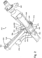
- Fig. 2 is a partial bottom perspective view omitting the lift mechanism, air spring and shock absorber and showing the connection between the spring beam and the axle.
- the mid-lift axle/suspension system 310 is of a well-established general type, to be installed ahead of the drive axle of a tractor.
- each spring 318 has an eye holding a pivot bush 322 with a conventional straddle-mount centre pin extending through a rubber cylinder and received in a mounting hole of the hanger 316 (shown broken away in Fig. 1 ).
- the rear end 326 of the spring beam 318 is fixed to the axle 332 by a spring seat 372 having upper and lower seat portions 370,371, and a connector sleeve 331 joined to the spring seat 372 by U-bolts 376 and welds 375.
- the top spring seat part 370 also provides lower mountings 384,380 for a shock absorber 382 and an air spring 324, the top ends of which are fixed to the chassis frame above.
- the axle 332 has a straight tubular body extending between the spring beam 318 and at each end a raised extension or gooseneck carrying the axle spindle. At each side an air-actuated lift mechanism 381 is mounted to the frame through the hanger 316 and operates to raise the axle via a lift arm 379 projecting from it. There may also be a brake system carried on the axle and/or beam and spring seat assemblies: the torque plate 307 of such a brake system is shown.
- Fig. 2 also shows features of an axle/beam connection newly proposed in WO2012/044802 whereby instead of bolting or welding directly to the axle body 332, a metal connector sleeve 331 is fitted around the axle 332 and a circumferential series of depressions 306 is formed in both sleeve and axle simultaneously, by a crimping or swaging process, forming a strong and rigid interlock connection.
- US-A-4166640 describes a trailer suspension in which a bush connecting the suspension beam to the frame hanger has upper and lower indented voids in the elastomer infill to reduce the vertical spring rate relative to that along the beam.
- Example rates given are 4380 N/mm (25,000 lbf/in) vertical and 8760 N/mm (50,000 lbf/in) horizontal.
- US-A-4166640 discloses the preamble of claim 1.
- US2002/0130480A also shows a bushing for the hanger end of a truck suspension beam in which the vertical compliance is increased relative to the horizontal.
- the elastomer infill is cylindrical, but the shell of the bushing is has top and bottom bulges forming voids above and below the infill.
- US-A-3147964 shows a rubber bushing for an automobile suspension with upper and lower voids above and below the bushing infill.
- Axle/suspension systems are always subject to a desire to reduce weight while maintaining effectiveness, because commercial vehicles' value depends on load-carrying ability.
- Increasing recent requirements for safety and emission control systems also add weight, detracting further from load-carrying ability and putting a further premium on weight saving in the body, frame and suspension of the heavy-duty vehicle.
- the invention as specified in claim 1 provides an axle and suspension system for a heavy-duty vehicle, having a vehicle frame with a longitudinal axis corresponding to a driving direction of the vehicle, the system comprising a vehicle axle extending transversely and having first and second ends; a suspension assembly at each end of the axle to support the axle, each suspension assembly comprising a frame mount such as a frame hanger fixedly attached to, or for fixed attachment to, a vehicle frame; a rigid longitudinal suspension beam connected fixedly to the axle at an axle-to-beam connection structure and pivotably to the frame mount through a resilient bush, so as to connect the axle to the frame mount; the resilient bush having a ratio of longitudinal stiffness (spring rate) to vertical stiffness (spring rate) of at least 10:1, desirably at least 15:1, especially at least 20:1, preferably at least 25:1 and more preferably at least 30:1. Usually the ratio is not more than 75:1.
- the resilient bush will generally have a structure with an inner mount unit connected to or comprised in one of the beam and frame mount, an outer mount connected to or comprised in the other of the beam and frame mount and an elastic spring infill portion, typically comprising one or more elastomer elements, extending between the inner mount unit and outer mounts and providing for resilient movement between them in all radial directions relative to the bush axis, including direction components of the longitudinal direction along the length of the rigid beam between the pivot and axle, and the vertical direction - perpendicular to the longitudinal direction - corresponding to movement of the beam pivot up and down relative to the vehicle frame.
- the vertical direction might not be exactly vertical, depending on the geometry and instantaneous position of the suspension, and can alternatively be defined as the radial direction perpendicular to the direction of maximum radial stiffness of the bush.
- the bush in the system may be described in terms of its directions of maximum and minimum stiffness or spring rate (minimum and maximum compliance) which are perpendicular to one another and to the axis of the bush and may exhibit the stiffness/spring rate ratios specified above, or alternatively with reference to horizontal and vertical directions in the axle/suspension system, or with reference to the longitudinal direction of the beam and the direction perpendicular to it.
- an inner mount unit of the bush is fixed to the frame mount and an outer mount to the beam.
- the beam may have an opening receiving the bush, engaging the outer mount thereof which is usually a shell or casing around the elastic infill portion although in some cases an elastomer element may directly engage the surrounding mount/beam opening.
- the inner mount unit may comprise an axially-projecting pin for straddle mounting, an open tube for bolting through, or any other suitable mount form.
- the limit of vertical relative movement (vertical compliance or travel) available at the resilient bush axis is at least 15 mm, preferably at least 20 mm. Desirably such a range of vertical relative movement is available both above and below a neutral (rest, static or centre) position i.e. at least ⁇ 12 mm, preferably at least ⁇ 15 mm, more preferably at least ⁇ 20 mm.
- the compliance and displacement range in one vertical direction are not necessarily identical to those in the other, for example depending on static vertical load at the bush, but often this static vertical load is small or negligible and causes little or no relative vertical displacement.
- the longitudinal (substantially horizontal, maximum stiffness) displacement or compliance available is desirably not more than ⁇ 10 mm, preferably not more than ⁇ 7 mm, more preferably not more than ⁇ 5 mm from a neutral longitudinal position, to maintain positional stability of the axle as in conventional systems.
- the longitudinal/horizontal/maximum stiffness rate is at least 30,000 N/mm, more preferably at least 40,000 N/mm. Usually it is not more than 60,000 N/mm, more preferably not more than 50,000 N/mm. Typically the vertical/minimum stiffness rate is not more than 2,000 N/mm, more preferably not more than 1,500 N/mm. Usually the vertical/minimum stiffness rate is at least 500 N/mm, more preferably at least 700 N/mm.
- the rigid beam is preferably of a fabricated construction, that is to say at least the body of the beam being formed or assembled from one or more sheet-form or plate-form metal elements rather than cast or forged as a solid body, although the latter is an option.
- This enables significant weight and cost reduction, including weight reduction relative to spring beams (which must be thick and heavy to provide sufficient bending strength to carry vehicle weight).
- the beam or at least the main body thereof desirably has opposed spaced side walls, such as an open channel or box section. Spaced side walls in sheet form can be formed with recesses or through-holes corresponding to and receiving an exterior of the axle.
- a rigid axle/beam connection may then be made securely by engagement of the beam wall edges with the axle, or with layer-form or sleeve-form axle connector elements such as a connector sleeve fitting around the axle, obviating heavy solid clamp assemblies.
- a connector sleeve may be connected to the axle by means of complementary indentations of the sleeve and axle, desirably inward, desirably plural, desirably in an array distributed circumferentially around the sleeve and axle.
- these indentations are formed simultaneously in sleeve and axle with the sleeve fitted around the axle e.g. as described in WO2012/044802 .
- axle/beam connection does not comprise any weld onto the axle.
- the mentioned sleeve or other layer-form connector may be connected to the beam by welding, e.g. around a conforming recess formed in the beam such as in one or more side walls or vertical walls thereof.
- axle/beam connection structure may be used, however, including known connection structures using any of seats, clamps, bolts and the like.
- the axle may be a hollow tubular or fabricated axle, at least at an axle body portion to which the beams connect.
- the ends of the axle may have supplementary formations bearing axle spindles.
- the axle ends may have gooseneck or other offset formations whereby the axes of the axle spindles are above an axis of the axle body.
- the axle may carry a brake system for the wheels thereof.
- the system is an air-ride suspension system, comprising at least one air spring connecting between the beams and/or axle below and the vehicle frame above.
- Such an air spring mount may be fabricated on the upper side of the beam above, adjacent or behind the axle/beam connection.
- the axle/suspension system may be a lift axle system, comprising lift mechanism for lifting the axle relative to the vehicle frame with upward pivoting of the beams. There may be respective subsidiary lift mechanisms at the two sides of the system.
- the or each lift mechanism may comprise an actuator element - usually operable by extension, such as a pneumatic or hydraulic element or a pre-compressed spring - acting between a fixed mounting e.g. fixed onto or relative to the frame through a hanger providing the frame mounting of the beam, and a driven abutment fixed to the axle or beam at a distal position thereof, i.e. spaced from the pivot e.g. adjacent the axle.
- shock absorbers may be included in the suspension system, such as in each suspension assembly, a lower shock absorber support may be provided on top of the beam.
- An upper shock absorber support may be separately provided to the vehicle frame above, or integrated into a frame mounting element such as a hanger which also carries the pivot connection for the beam.
- the axle is usually a non-steering axle, but the invention is also applicable to steered axles.
- the resilient bush at the pivotal mounting of the beam to the frame mount are now discussed.
- a compliance ratio between higher longitudinal and lower vertical spring rates can be provided by means of upper and lower voids in an elastomer infill structure of the bush between the inner and outer mounts.
- Such voids are preferred in the resilient bush used herein.
- the bush may comprise front and rear elastic elements extending solidly between the inner and outer mounts to provide the longitudinal stiffness, with voids above and below whereby the vertical stiffness arises primarily from vertical shear of the front and rear elements.
- each of front and rear elastomeric elements has two or more metal interleaves.
- these interleaves are desirably plate forms, usually bonded intimately to the elastomer e.g. as a result of curing/vulcanisation in contact. They may have an inwardly-concave or outwardly-convex form to complement the axial geometry of the bush.
- the inner mount unit is or comprises a solid body, such as a metal body, with outwardly-convex front and rear faces, e.g. outwardly angled sub-faces, to promote uniform compression of the front and rear elastomer elements. Again, this is a feature known in itself.
- the front/rear face shape of the inner mount unit may conform to the shape of metal interleaves as discussed above.
- the upper and lower voids may extend substantially or entirely to the outer mount and/or substantially or entirely to the inner mount unit, to maximise the space for low-resilience (high-compliance) relative movement in the vertical direction.
- resilient bumpers are provided, on upper and lower faces of the inner mount unit and/or on top and bottom inward faces of the outer mount, to avoid damage if these mounts are relatively displaced to their vertical limit.
- Such bumpers may be of elastomer e.g. as present elsewhere in the bush, or of other plastics material. Elastomer parts of the bush may be formed separately from one another or formed together, such as integrated into a one-piece whole, e.g.
- the inner and outer bush mount components can move through at least 50%, more preferably at least 60% or at least 70% of their maximum vertical relative movement before any abutting contact e.g. at a bumper as mentioned above. Further displacement after such contact may be by compressing one or more bumpers. There may be an increase, e.g. a progressive increase, in spring rate for further displacement beyond the contact.
- the beam bushes - as with known beam bushes e.g. in trailer suspensions - need to accommodate movement corresponding to pivoting of the beam, usually with resilient torsion in the bush. Such movement can be accommodated where front and rear elastomer elements are separated by substantial upper and lower voids, as described above. Or, additional means may be provided to accommodate torsional movement with or without resilience. According to one preferred embodiment in the present proposals, this is achieved by providing an internal bush in the inner mount unit.
- this unit may comprise an outer piece or block with an internal cavity extending in the axial direction of the bush and containing an elastomer element - such as a cylindrical elastomer element which may be without voids - and a rigid central mounting part such as a tube or pin extending through this elastomer element.
- the internal bush provides for torsional deformation of the inner elastomeric element when there is relative rotation of the central mounting part and the surrounding piece of the inner mounting unit, thereby uncoupling part of the torsional spring performance from the circumferentially highly discontinuous spring elements providing the overall characteristic for displacements transverse to the axis.
- one suitable form of bushing used in the invention comprises an outer mount, an inner mount unit positioned within the outer mount at a spacing, front and rear elastomeric elements connecting between the outer mount and inner mount unit at front and rear positions, defining top and bottom voids substantially separating the front and rear elastomer elements, top and bottom protection bumpers facing onto the top and bottom voids to prevent direct rigid contact between the inner mount unit and outer mount at maximum vertical relative displacement, and metal interleaf elements dividing the front and rear elastomer elements to limit local strain therein; the inner mount unit defining an inner cavity containing an elastomer element and a rigid central mounting part (at which the bush is fixed to the relevant external component such as the frame mount of the suspension) inside the elastomer element.
- This pivot bush can be highly directional in characteristics. It is therefore preferred to provide one or more circumferentially-localised abutment formations on the outer mount to engage mechanically with corresponding circumferentially-localised abutment formations on the suspension assembly component to which it is fixed - in the beam or frame mount, usually the beam - to hold the bush at a predetermined rotational alignment relative to that component.
- An alternative is to make the bush non-circular and fit in a correspondingly non-circular recess or mounting of the component, to prevent the bush from turning out of alignment.
- the elastomer elements of bushes require substantial radial pre-compression to avoid any tension in operation.
- this may be achieved, as is well known, by providing the casing or shell (outer mount) of the free (initially formed, uncompressed) bush as two or more separate spaced parts which are pushed together e.g. to form a continuous tubular form when the bush is compressed to its operational condition.
- the above preferred form of the bush with front and rear or other elastomer elements may have separate e.g. front and rear casing (outer mount) parts attached to these.
- a further preferred proposal herein is to provide interlock formations of these outer mount or casing parts which overlap or interlock circumferentially in the installed position/condition of the bush.
- One casing part may have a projection or series of projections extending into a corresponding recess or series of recesses of another casing part. This inhibits the parts of the bush from moving axially relative to one another, for example inhibiting possible "walking" of the bush out of its mounting.
- a preferred mounting for the bush is a metal tube, preferably comprised in or fixed at the pivot end of the rigid beam, preferably fixed by welding.
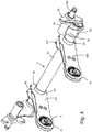
- the axle/suspension system 1 for a mid-lift axle on the tractor of a tractor-trailer vehicle comprises an axle 5 and a suspension assembly 2 at each end of the axle 5 by which the axle is supported relative to longitudinal frame members (not shown, may be conventional) extending along each side of the vehicle.
- Each suspension assembly 2 includes a rigid beam 4 - a trailing beam, in this example, although it can be a leading beam in other embodiments - connected at its front end 41 through a pivotal connection 21 to the bottom end of a frame hanger 3 fixed to the respective frame member.
- the beam 4 is fixed to the axle 5 at its rear end 42.
- the hanger 3 depends from a fixing plate 31 bolted to the frame in a generally known manner, and provides at its bottom end a pivot mounting 32 with a pair of spaced cheek flanges 321.
- the beam 4 - see especially Figs. 4 and 5 - is a rigid fabricated construction made from steel plate, having a box section with opposed side plates 431, a top plate 432 and a bottom plate.
- a cylindrical bush mounting tube 44 is fixed at the front end (pivot end) 41 of the beam by welding into circular holes at the ends of the side plates 431, with its axis horizontal.
- the side plates 431 At its rear (axle end) 42 of the beam the side plates 431 have circular openings 46 receiving a body tube of the axle and fixed to it as described later.
- the axle 5 is a fabricated hollow construction having a main cylindrical body tube 51, a gooseneck or crank portion 52 attached at each end carrying a spindle mounting tube 53 in which a spindle 54 for a wheel 57 is fixed.
- a mid-lift axle such a gooseneck or drop provides clearance e.g. for transmission components.
- axles e.g. tag axles this may not be needed and the axle can be straight.
- the axle/suspension system 1 also incorporates brake systems for the wheels 57: details may be as known and Fig. 4 shows a torque plate 55 of this; other types of brakes may be used.
- crank or drop portion 52 comprises a sleeve 521 fitting around the end of the axle and fixed to it by means of a set of complementary inward indentations of the sleeve and axle distributed circumferentially around the sleeve and axle. These indentations are formed simultaneously in sleeve and axle with the sleeve fitted around the axle e.g. as described in WO2012/044802 . Desirably this axle/crank connection does not comprise any weld onto the axle.
- the axle/beam connection 25 is formed without any direct weld or bolting to the axle tube 51.
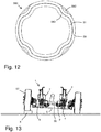
- a metal connector sleeve 58 fits closely around the axle tube 51 at the region to be connected, and a crimped joint 580 is created by forming a series of circumferentially-spaced indentations 582,583 around these tubes, by a compressive mechanical crimping or swaging device which indents them simultaneously, as shown in Fig. 12 .
- the plastic deformation of the connecting sleeve indentations 582 is more than that of the axle tube indentations 583 within, so that they are then pressed together giving high strength and rigidity.
- the outside surface of the connecting sleeve 58 is then welded around the circular axle holes 46 in the beam to fix the axle rigidly to the beam. Because the axle tube 51 is not heat-affected by direct welding it does not suffer strength reduction and a lighter-section axle tube 51 can be used than in normal welded connections; this can reduce overall weight.
- the low axis of the axle body tube 51 relative to the wheel spindles 54 in the present construction provides additional clearance for structures below the vehicle, especially for lifting the axle.
- air spring mounting points 437 with suitable fastener openings are provided along the top of each beam side plate 431.
- a fabricated air spring mounting platform 47 ( Fig. 3 ) is mounted on these and supports the bottom plate 71 of an air spring 7, whose top plate 72 connects to a top mounting bracket 73 for fixing to the vehicle frame member above.
- the nature and role of such air springs is well-known and need not be explained further.
- the positions of the air springs relative to the axle and beams may vary in line with the technical context and skilled knowledge, for example the air spring may be mounted behind (beyond) the axle on an extension of or from the beam end.
- Each beam 4 can be regarded as having a beam body 43 extending between the pivot end and axle end securing formations described above and having the mentioned box section.
- the mid-part of the beam body 43 provides a mounting point 438, again with suitable fastener openings, for a discrete fabricated mount component 48 which provides a lower mounting for a shock absorber (damper) 8 whose upper end is mounted to an upper mounting 38 provided as part of the hanger 3, although it may alternatively be fixed directly to the vehicle frame.
- the fabricated mount component 48 on the beam also has an integral inward arm 488 constituting an upper reaction point for an axle lift mechanism 9.
- the lift mechanism 9 comprises an extensible lift actuator 91, such as a pneumatic actuator, operable to push up on the arm 488 of component 48 above relative to a fixed lift mounting abutment 39 below which projects from the bottom of the hanger 3.
- Controlled extension of the lift actuators 91 on either side of the suspension lifts the axle 5 towards the frame, with pivoting at the hanger-beam connections 21, lifting the wheels 57 out of road contact as is well known.
- a support cross-strut 35 connects rigidly between the bottom ends of the two hangers 3 to stabilise the structure. This strut operates to react directly lateral loads arising during vehicle turning and reduce torsional loads into the vehicle frame above.
- the described construction relies largely on fabricated components, made from stock plate and tube elements by forming and joining and which can be light in weight.
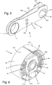
- a bush 6 - shown generally in Fig. 4 , in more detail in Fig. 6 , and schematically in operation in Figs. 10 and 11 - is fixed in the bush mounting tube 44 at the front end of each beam 4.
- the special function of the bush 6 is to provide substantial independent vertical compliance at either side of the suspension system 1 so that the rigidity of the axle/beam assembly 4,5 does not disrupt the steering and handling of the tractor when cornering or passing over uneven ground.
- the bush 6 provides an unusually large and soft vertical compliance, combined with the conventionally restricted longitudinal compliance necessary for stability and handling.
- the main functional elements of the bushing 6 are an outer mount in the form of a cylindrical casing or shell 63, an inner mount unit 61 in the form of a generally prismatic metal block or piece 611 extending axially within the outer shell 63, and an elastomer infill 64 supporting the inner mount unit 61 coaxially with the outer shell 63.
- the outer shell 63 may be of steel.
- the elastomer elements of the infill may be formed and bonded by moulding and curing onto the metal elements, in a known manner which need not be described here.
- the bushing provides for an unusually large vertical displacement, e.g. about ⁇ 25 mm, and may be typically from 130 to 180 mm in diameter.
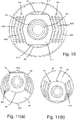
- the combination of low vertical stiffness with high longitudinal stiffness is achieved by front and rear elastomer elements 641 essentially confined to the regions in front of and behind the block 611 of the inner mount unit, with substantial upper and lower voids 66,67 defined between the inner mount unit 61 and the top and bottom regions of the outer shells 63. Only a small elastomer bumper piece 65 on each of the top and bottom faces 612 of the inner mount block 611 separates them. Figs.
- FIG. 11(a), (b) shows the vertical displacement modes of the bush 6 showing how the front and rear elements 641, which need provide only a conventional limited longitudinal displacement (e.g. about ⁇ 3 to 4 mm) which would not require large radial dimensions, must nevertheless be large in radial extent to be able to shear sufficiently to allow for the large vertical displacement.
- a set of metal interleaves 643 is provided to separate each element into elastomer sub-layers 642.
- the strain in each elastomer layer 642 is limited and controlled by the division into sub-layers and the adhesion to the metal interleaves 643, enabling the large shear deformations shown without damage.
- the metal block 611 of the inner mount unit 61 has convex side faces 613 - provided in this embodiment as an angled pair of flat faces - for efficient compression of the elastomer giving a high spring rate on longitudinal displacement.
- the metal interleaves 643 have correspondingly angled or bent forms to complement this shape.
- the bushing 6 is installed in a pre-compressed condition of the elastomer infill 64 by providing the outer shell 63 as a pair of shell parts 631 bonded on the respective elastomer elements 641.
- the shell parts 631 form the cylindrical shell 63 with a joint line 632 where their edges meet.
- a particular feature of the present embodiment is the provision of an internal bush 69 within the inner mount unit 61 itself.
- the main metal block 611 of the inner unit has a central axial cylindrical through-hole 615 occupied by a rigid metal centre mount piece 617 with a cylindrical body and by an inner elastomer infill 616 which surrounds and supporting the centre mount piece 617 in the central hole for degree of resilient radial and relative rotational movement between the centre mount piece 617 and the block 611.
- the centre mount piece is a tube 617 e.g. for bolt-through mounting.
- Fig. 7 shows an alternative where the centre mount piece is a bar pin 618 with projecting ends for straddle mounting.
- the inner elastomer infill 616 is bonded to the adjacent metal components to provide resilient torsional resistance. It is a simple cylindrical sleeve, giving uniform small radial compliance in all directions. It enables the torsional response of the bushing to the - generally small - angular movements of the beam 4 to be uncoupled to some extent from its resilient response to vertical movements of the inner unit 61 relative to the outer sleeve 63 with flexion of the main elastomer elements 641.
- Fig. 8 shows a refinement in which the ends of the shell parts 631 have interlocking formations - in this case a single projection 635 on one complementing a single recess 636 on the other - so as to inhibit relative axial movement which might lead to the bush "walking" out of its mounting tube 44. It will be understood that a variety of different casing formations can be used to achieve this advantage.
- Fig. 9 shows an optional refinement for aligning the bush 6 rotationally in its mounting and inhibiting its rotation, having in mind that the difference between its vertical and horizontal stiffness is both large and important, and the bush must be correctly oriented relative to the system and the ground.
- the casing 63 of the bush is formed with a radially-displaceable spring tang 639 having outward projections 638. These can engage selectively in a corresponding slot 446 in the wall of the mounting tube 44 when the bush is assembled and mounted.
- the longitudinal rate may be from 40,000 to 50,000 N/mm and the vertical rate from 700 to 1400 N/mm.
- the ratio of longitudinal to vertical stiffness (spring rate) may be e.g. about 35:1 and this is found to give good compliance and driving performance with a mid-lift axle. Other ratios and rates may be used depending on the kind of vehicle, expected axle load and the like.
- Fig. 11 shows the axle/suspension system in operation with the wheels 57 moving over uneven terrain X, and a resulting tilt in the axle 5 being accommodated by substantial vertical displacement of the pivot connection bushing 6 on the left-hand side of the figure, so that the otherwise rigid axle-beam set does not upset the vehicle frame above.
Landscapes
- Engineering & Computer Science (AREA)
- Mechanical Engineering (AREA)
- General Engineering & Computer Science (AREA)
- Manufacturing & Machinery (AREA)
- Vehicle Body Suspensions (AREA)
Priority Applications (1)
| Application Number | Priority Date | Filing Date | Title |
|---|---|---|---|
| PL16825334T PL3386780T3 (pl) | 2015-12-11 | 2016-12-09 | Osie/układy zawieszenia |
Applications Claiming Priority (2)
| Application Number | Priority Date | Filing Date | Title |
|---|---|---|---|
| GBGB1521841.5A GB201521841D0 (en) | 2015-12-11 | 2015-12-11 | Axle/suspension systems |
| PCT/EP2016/080384 WO2017097957A1 (en) | 2015-12-11 | 2016-12-09 | Axle/suspension systems |
Publications (2)
| Publication Number | Publication Date |
|---|---|
| EP3386780A1 EP3386780A1 (en) | 2018-10-17 |
| EP3386780B1 true EP3386780B1 (en) | 2020-08-26 |
Family
ID=55274555
Family Applications (1)
| Application Number | Title | Priority Date | Filing Date |
|---|---|---|---|
| EP16825334.2A Active EP3386780B1 (en) | 2015-12-11 | 2016-12-09 | Axle and suspension systems |
Country Status (12)
| Country | Link |
|---|---|
| US (1) | US10807430B2 (pl) |
| EP (1) | EP3386780B1 (pl) |
| CN (1) | CN108778786B (pl) |
| AU (1) | AU2016368514A1 (pl) |
| BR (1) | BR112018011612B1 (pl) |
| CA (1) | CA3005689A1 (pl) |
| DK (1) | DK3386780T3 (pl) |
| ES (1) | ES2830149T3 (pl) |
| GB (1) | GB201521841D0 (pl) |
| MX (1) | MX2018006600A (pl) |
| PL (1) | PL3386780T3 (pl) |
| WO (1) | WO2017097957A1 (pl) |
Families Citing this family (11)
| Publication number | Priority date | Publication date | Assignee | Title |
|---|---|---|---|---|
| US11014419B2 (en) * | 2017-03-21 | 2021-05-25 | Arctic Cat Inc. | Off-road utility vehicle |
| US10543726B2 (en) * | 2017-09-25 | 2020-01-28 | Ford Global Technologies, Llc | Lower control arm |
| GB201717371D0 (en) * | 2017-10-23 | 2017-12-06 | Hendrickson United Kingdom Ltd | Heavy-duty connections e.g. for axle/suspension systems |
| KR102771977B1 (ko) * | 2018-10-01 | 2025-02-21 | 디엔 오토모티브 저머니 게엠베하 | 부시(bush) |
| US11035430B2 (en) * | 2018-10-22 | 2021-06-15 | Maryam Ghassabzadeh Saryazdi | Rotary damping |
| KR102714870B1 (ko) * | 2019-07-19 | 2024-10-08 | 현대자동차주식회사 | 튜닝 자유도 개선형 부시 및 현가 시스템 |
| CN111590266B (zh) * | 2020-06-19 | 2021-10-15 | 广州电力机车有限公司 | 一种矿车拉杆座焊接维修方法 |
| EP3954556A1 (en) * | 2020-08-11 | 2022-02-16 | Volvo Truck Corporation | Bushing for a suspension and vehicle comprising such a bushing |
| DE102021108655A1 (de) * | 2021-04-07 | 2022-10-13 | Bayerische Motoren Werke Aktiengesellschaft | Achsträgerlagerung für eine, insbesondere mittels Elektromotor angetriebene, Achse eines Kraftfahrzeugs |
| CN115143234A (zh) * | 2022-07-20 | 2022-10-04 | 贵州詹阳动力重工有限公司 | 一种轮式挖掘装载机减振结构 |
| DE102023206074A1 (de) * | 2023-06-28 | 2025-01-02 | Zf Friedrichshafen Ag | Fahrwerk eines Kraftfahrzeuges |
Family Cites Families (29)
| Publication number | Priority date | Publication date | Assignee | Title |
|---|---|---|---|---|
| DE1038416B (de) | 1956-06-28 | 1958-09-04 | Lemfoerder Metallwaren G M B H | Federbuchse, insbesondere zum Lagern des Federbolzens bei Federaufhaengungen von Kraftfahrzeugen |
| US3147964A (en) | 1963-04-26 | 1964-09-08 | Gen Tire & Rubber Co | Closed end-variable spring rate bushing |
| US3508745A (en) | 1967-07-13 | 1970-04-28 | Gen Tire & Rubber Co | Elastomeric closed end triple-rate bushing |
| FR2214067B1 (pl) | 1973-01-12 | 1976-05-14 | Paulstra Sa | |
| DE7718677U1 (de) | 1977-06-14 | 1982-12-02 | Lemförder Metallwaren AG, 2844 Lemförde | Federelement, insbesondere zur elastischen Lagerung von Antriebs- oder sonstigen Aggregaten in Kraftfahrzeugen |
| US4166640B1 (en) | 1978-04-14 | 1994-03-22 | Boler Company Inc | Axle suspension for wheeled vehicles |
| GB2071265B (en) | 1980-01-09 | 1984-06-27 | Iao Industrie Riunite Spa | Engine elastic mounting |
| US4732407A (en) | 1986-06-10 | 1988-03-22 | Fuji Jukogyo Kabushiki Kaisha | Suspension system for a motor vehicle |
| JPH06103057B2 (ja) | 1987-12-07 | 1994-12-14 | 東海ゴム工業株式会社 | 流体封入式防振ブッシュ |
| US4991868A (en) | 1989-12-19 | 1991-02-12 | The Boler Company | Vehicle suspension beam pivot connection |
| JPH0442937U (pl) | 1990-08-09 | 1992-04-13 | ||
| JPH07119778A (ja) | 1993-09-02 | 1995-05-09 | Tokai Rubber Ind Ltd | ブラケット付防振ゴムおよびブラケット付防振ゴムの製造方法 |
| FR2711198B1 (fr) * | 1993-10-11 | 1996-01-26 | Hutchinson | Biellette de reprise de couple pour moteur de véhicule . |
| DE4438932C2 (de) | 1994-10-31 | 1998-07-02 | Daimler Benz Ag | Hydrolager |
| WO1997035123A1 (en) | 1996-03-21 | 1997-09-25 | The Boler Company | Voided bushing for vehicle suspensions |
| US5690353A (en) * | 1996-05-09 | 1997-11-25 | Suspensions Incorporated | Suspension system with improved beam |
| US5996981A (en) | 1996-08-28 | 1999-12-07 | The Boler Company | Reduced size bushing for beam-type axle suspension system |
| US6585223B1 (en) | 1999-09-14 | 2003-07-01 | Meritor Heavy Vehicle Suspensions, Inc. | Variable compliance bushing |
| US20020130480A1 (en) | 2001-03-14 | 2002-09-19 | Vandenberg Ervin | Variable compliance pivot assembly and suspension system for use therewith |
| JP2002362123A (ja) * | 2001-06-01 | 2002-12-18 | Nissan Motor Co Ltd | フロントサスペンション構造 |
| US6854750B2 (en) | 2001-12-14 | 2005-02-15 | Meritor Light Vehicle Technology, Llc | Variable rate bushing for stabilizer bar |
| US7207583B2 (en) | 2002-01-16 | 2007-04-24 | Hendrickson Usa, L.L.C. | Spacer apparatus for suspension beam bushing assemblies |
| DE102004062807A1 (de) * | 2004-12-27 | 2006-07-20 | Jörn GmbH | Elastisches Lager mit einer Elastomermetallbuchse für ein Kraftfahrzeug |
| CN2854202Y (zh) * | 2005-12-16 | 2007-01-03 | 李忠富 | 轿车弹性悬臂用橡胶缓冲套 |
| DE102007024741A1 (de) | 2007-05-26 | 2008-12-04 | Jörn GmbH | Elastisches Lager mit einer Elastomermetallbuchse, insbesondere für die Lagerung eines Stabi-Lenkers an einem Kraftfahrzeug |
| DE202011110639U1 (de) | 2010-09-30 | 2015-09-03 | Hendrickson Usa, L.L.C. | Achse-zu-Träger-Verbindung für Schwerlastfahrzeuge |
| CN202971697U (zh) * | 2012-12-19 | 2013-06-05 | 安徽中鼎减震橡胶技术有限公司 | 一种衬套 |
| DE102015016142B4 (de) * | 2015-12-11 | 2018-05-17 | Jörn GmbH | Elastisches Lager zur Verbindung zweier Bauteile |
| DE102015016454B4 (de) * | 2015-12-21 | 2018-02-08 | Jörn GmbH | Elastisches Lager |
-
2015
- 2015-12-11 GB GBGB1521841.5A patent/GB201521841D0/en not_active Ceased
-
2016
- 2016-12-09 AU AU2016368514A patent/AU2016368514A1/en not_active Abandoned
- 2016-12-09 CA CA3005689A patent/CA3005689A1/en not_active Abandoned
- 2016-12-09 WO PCT/EP2016/080384 patent/WO2017097957A1/en not_active Ceased
- 2016-12-09 PL PL16825334T patent/PL3386780T3/pl unknown
- 2016-12-09 MX MX2018006600A patent/MX2018006600A/es unknown
- 2016-12-09 ES ES16825334T patent/ES2830149T3/es active Active
- 2016-12-09 BR BR112018011612-2A patent/BR112018011612B1/pt active IP Right Grant
- 2016-12-09 US US15/778,130 patent/US10807430B2/en active Active
- 2016-12-09 EP EP16825334.2A patent/EP3386780B1/en active Active
- 2016-12-09 CN CN201680072485.2A patent/CN108778786B/zh active Active
- 2016-12-09 DK DK16825334.2T patent/DK3386780T3/da active
Non-Patent Citations (1)
| Title |
|---|
| None * |
Also Published As
| Publication number | Publication date |
|---|---|
| EP3386780A1 (en) | 2018-10-17 |
| DK3386780T3 (da) | 2020-10-26 |
| BR112018011612B1 (pt) | 2022-08-23 |
| ES2830149T3 (es) | 2021-06-03 |
| CN108778786A (zh) | 2018-11-09 |
| AU2016368514A1 (en) | 2018-06-07 |
| CN108778786B (zh) | 2021-12-28 |
| WO2017097957A1 (en) | 2017-06-15 |
| GB201521841D0 (en) | 2016-01-27 |
| US10807430B2 (en) | 2020-10-20 |
| US20180354330A1 (en) | 2018-12-13 |
| CA3005689A1 (en) | 2017-06-15 |
| BR112018011612A2 (pt) | 2018-11-27 |
| PL3386780T3 (pl) | 2021-04-19 |
| MX2018006600A (es) | 2018-09-27 |
Similar Documents
| Publication | Publication Date | Title |
|---|---|---|
| EP3386780B1 (en) | Axle and suspension systems | |
| AU666572B2 (en) | Axle suspension systems | |
| CN103140359B (zh) | 重载车辆的车轴-梁连接件 | |
| CN102421613B (zh) | 重型专业车辆的悬挂系统 | |
| US9079467B2 (en) | Heavy-duty vehicle axle-to-beam or crossbrace-to-beam connection | |
| US9193236B2 (en) | Heavy-duty vehicle axle-to-beam or crossbrace-to-beam connection | |
| AU716456B2 (en) | Trailing arm suspension with articulated axle mounting | |
| EP2525989B1 (en) | Heavy-duty axle-to-beam connection | |
| US20100059958A1 (en) | Heavy vehicle sway bar with redundancy (backup safety feature) | |
| US12472787B2 (en) | Load equalizer assembly for tandem steer suspension | |
| NZ272361A (en) | Vehicle axle rigidly attached to beam allowing for attaching braking mechanism to beam, rather than axle | |
| MXPA93006307A (en) | Axle suspension system for overhead vehicles |
Legal Events
| Date | Code | Title | Description |
|---|---|---|---|
| STAA | Information on the status of an ep patent application or granted ep patent |
Free format text: STATUS: UNKNOWN |
|
| STAA | Information on the status of an ep patent application or granted ep patent |
Free format text: STATUS: THE INTERNATIONAL PUBLICATION HAS BEEN MADE |
|
| PUAI | Public reference made under article 153(3) epc to a published international application that has entered the european phase |
Free format text: ORIGINAL CODE: 0009012 |
|
| STAA | Information on the status of an ep patent application or granted ep patent |
Free format text: STATUS: REQUEST FOR EXAMINATION WAS MADE |
|
| 17P | Request for examination filed |
Effective date: 20180612 |
|
| AK | Designated contracting states |
Kind code of ref document: A1 Designated state(s): AL AT BE BG CH CY CZ DE DK EE ES FI FR GB GR HR HU IE IS IT LI LT LU LV MC MK MT NL NO PL PT RO RS SE SI SK SM TR |
|
| AX | Request for extension of the european patent |
Extension state: BA ME |
|
| DAV | Request for validation of the european patent (deleted) | ||
| DAX | Request for extension of the european patent (deleted) | ||
| GRAP | Despatch of communication of intention to grant a patent |
Free format text: ORIGINAL CODE: EPIDOSNIGR1 |
|
| STAA | Information on the status of an ep patent application or granted ep patent |
Free format text: STATUS: GRANT OF PATENT IS INTENDED |
|
| INTG | Intention to grant announced |
Effective date: 20200318 |
|
| GRAS | Grant fee paid |
Free format text: ORIGINAL CODE: EPIDOSNIGR3 |
|
| GRAA | (expected) grant |
Free format text: ORIGINAL CODE: 0009210 |
|
| STAA | Information on the status of an ep patent application or granted ep patent |
Free format text: STATUS: THE PATENT HAS BEEN GRANTED |
|
| AK | Designated contracting states |
Kind code of ref document: B1 Designated state(s): AL AT BE BG CH CY CZ DE DK EE ES FI FR GB GR HR HU IE IS IT LI LT LU LV MC MK MT NL NO PL PT RO RS SE SI SK SM TR |
|
| REG | Reference to a national code |
Ref country code: GB Ref legal event code: FG4D |
|
| REG | Reference to a national code |
Ref country code: CH Ref legal event code: EP |
|
| REG | Reference to a national code |
Ref country code: AT Ref legal event code: REF Ref document number: 1306038 Country of ref document: AT Kind code of ref document: T Effective date: 20200915 |
|
| REG | Reference to a national code |
Ref country code: IE Ref legal event code: FG4D |
|
| REG | Reference to a national code |
Ref country code: DE Ref legal event code: R096 Ref document number: 602016042881 Country of ref document: DE |
|
| REG | Reference to a national code |
Ref country code: DK Ref legal event code: T3 Effective date: 20201023 |
|
| REG | Reference to a national code |
Ref country code: SE Ref legal event code: TRGR |
|
| REG | Reference to a national code |
Ref country code: NL Ref legal event code: FP |
|
| REG | Reference to a national code |
Ref country code: LT Ref legal event code: MG4D |
|
| PG25 | Lapsed in a contracting state [announced via postgrant information from national office to epo] |
Ref country code: GR Free format text: LAPSE BECAUSE OF FAILURE TO SUBMIT A TRANSLATION OF THE DESCRIPTION OR TO PAY THE FEE WITHIN THE PRESCRIBED TIME-LIMIT Effective date: 20201127 Ref country code: LT Free format text: LAPSE BECAUSE OF FAILURE TO SUBMIT A TRANSLATION OF THE DESCRIPTION OR TO PAY THE FEE WITHIN THE PRESCRIBED TIME-LIMIT Effective date: 20200826 Ref country code: BG Free format text: LAPSE BECAUSE OF FAILURE TO SUBMIT A TRANSLATION OF THE DESCRIPTION OR TO PAY THE FEE WITHIN THE PRESCRIBED TIME-LIMIT Effective date: 20201126 Ref country code: NO Free format text: LAPSE BECAUSE OF FAILURE TO SUBMIT A TRANSLATION OF THE DESCRIPTION OR TO PAY THE FEE WITHIN THE PRESCRIBED TIME-LIMIT Effective date: 20201126 Ref country code: HR Free format text: LAPSE BECAUSE OF FAILURE TO SUBMIT A TRANSLATION OF THE DESCRIPTION OR TO PAY THE FEE WITHIN THE PRESCRIBED TIME-LIMIT Effective date: 20200826 Ref country code: PT Free format text: LAPSE BECAUSE OF FAILURE TO SUBMIT A TRANSLATION OF THE DESCRIPTION OR TO PAY THE FEE WITHIN THE PRESCRIBED TIME-LIMIT Effective date: 20201228 Ref country code: FI Free format text: LAPSE BECAUSE OF FAILURE TO SUBMIT A TRANSLATION OF THE DESCRIPTION OR TO PAY THE FEE WITHIN THE PRESCRIBED TIME-LIMIT Effective date: 20200826 |
|
| PG25 | Lapsed in a contracting state [announced via postgrant information from national office to epo] |
Ref country code: IS Free format text: LAPSE BECAUSE OF FAILURE TO SUBMIT A TRANSLATION OF THE DESCRIPTION OR TO PAY THE FEE WITHIN THE PRESCRIBED TIME-LIMIT Effective date: 20201226 Ref country code: LV Free format text: LAPSE BECAUSE OF FAILURE TO SUBMIT A TRANSLATION OF THE DESCRIPTION OR TO PAY THE FEE WITHIN THE PRESCRIBED TIME-LIMIT Effective date: 20200826 Ref country code: RS Free format text: LAPSE BECAUSE OF FAILURE TO SUBMIT A TRANSLATION OF THE DESCRIPTION OR TO PAY THE FEE WITHIN THE PRESCRIBED TIME-LIMIT Effective date: 20200826 |
|
| PG25 | Lapsed in a contracting state [announced via postgrant information from national office to epo] |
Ref country code: RO Free format text: LAPSE BECAUSE OF FAILURE TO SUBMIT A TRANSLATION OF THE DESCRIPTION OR TO PAY THE FEE WITHIN THE PRESCRIBED TIME-LIMIT Effective date: 20200826 Ref country code: CZ Free format text: LAPSE BECAUSE OF FAILURE TO SUBMIT A TRANSLATION OF THE DESCRIPTION OR TO PAY THE FEE WITHIN THE PRESCRIBED TIME-LIMIT Effective date: 20200826 Ref country code: SM Free format text: LAPSE BECAUSE OF FAILURE TO SUBMIT A TRANSLATION OF THE DESCRIPTION OR TO PAY THE FEE WITHIN THE PRESCRIBED TIME-LIMIT Effective date: 20200826 Ref country code: EE Free format text: LAPSE BECAUSE OF FAILURE TO SUBMIT A TRANSLATION OF THE DESCRIPTION OR TO PAY THE FEE WITHIN THE PRESCRIBED TIME-LIMIT Effective date: 20200826 |
|
| REG | Reference to a national code |
Ref country code: AT Ref legal event code: UEP Ref document number: 1306038 Country of ref document: AT Kind code of ref document: T Effective date: 20200826 |
|
| REG | Reference to a national code |
Ref country code: DE Ref legal event code: R097 Ref document number: 602016042881 Country of ref document: DE |
|
| PG25 | Lapsed in a contracting state [announced via postgrant information from national office to epo] |
Ref country code: AL Free format text: LAPSE BECAUSE OF FAILURE TO SUBMIT A TRANSLATION OF THE DESCRIPTION OR TO PAY THE FEE WITHIN THE PRESCRIBED TIME-LIMIT Effective date: 20200826 |
|
| REG | Reference to a national code |
Ref country code: ES Ref legal event code: FG2A Ref document number: 2830149 Country of ref document: ES Kind code of ref document: T3 Effective date: 20210603 |
|
| PG25 | Lapsed in a contracting state [announced via postgrant information from national office to epo] |
Ref country code: SK Free format text: LAPSE BECAUSE OF FAILURE TO SUBMIT A TRANSLATION OF THE DESCRIPTION OR TO PAY THE FEE WITHIN THE PRESCRIBED TIME-LIMIT Effective date: 20200826 |
|
| PLBE | No opposition filed within time limit |
Free format text: ORIGINAL CODE: 0009261 |
|
| STAA | Information on the status of an ep patent application or granted ep patent |
Free format text: STATUS: NO OPPOSITION FILED WITHIN TIME LIMIT |
|
| REG | Reference to a national code |
Ref country code: CH Ref legal event code: PL |
|
| 26N | No opposition filed |
Effective date: 20210527 |
|
| PG25 | Lapsed in a contracting state [announced via postgrant information from national office to epo] |
Ref country code: SI Free format text: LAPSE BECAUSE OF FAILURE TO SUBMIT A TRANSLATION OF THE DESCRIPTION OR TO PAY THE FEE WITHIN THE PRESCRIBED TIME-LIMIT Effective date: 20200826 Ref country code: MC Free format text: LAPSE BECAUSE OF FAILURE TO SUBMIT A TRANSLATION OF THE DESCRIPTION OR TO PAY THE FEE WITHIN THE PRESCRIBED TIME-LIMIT Effective date: 20200826 |
|
| REG | Reference to a national code |
Ref country code: BE Ref legal event code: MM Effective date: 20201231 |
|
| PG25 | Lapsed in a contracting state [announced via postgrant information from national office to epo] |
Ref country code: LU Free format text: LAPSE BECAUSE OF NON-PAYMENT OF DUE FEES Effective date: 20201209 |
|
| PG25 | Lapsed in a contracting state [announced via postgrant information from national office to epo] |
Ref country code: CH Free format text: LAPSE BECAUSE OF NON-PAYMENT OF DUE FEES Effective date: 20201231 Ref country code: LI Free format text: LAPSE BECAUSE OF NON-PAYMENT OF DUE FEES Effective date: 20201231 |
|
| PG25 | Lapsed in a contracting state [announced via postgrant information from national office to epo] |
Ref country code: TR Free format text: LAPSE BECAUSE OF FAILURE TO SUBMIT A TRANSLATION OF THE DESCRIPTION OR TO PAY THE FEE WITHIN THE PRESCRIBED TIME-LIMIT Effective date: 20200826 Ref country code: MT Free format text: LAPSE BECAUSE OF FAILURE TO SUBMIT A TRANSLATION OF THE DESCRIPTION OR TO PAY THE FEE WITHIN THE PRESCRIBED TIME-LIMIT Effective date: 20200826 Ref country code: CY Free format text: LAPSE BECAUSE OF FAILURE TO SUBMIT A TRANSLATION OF THE DESCRIPTION OR TO PAY THE FEE WITHIN THE PRESCRIBED TIME-LIMIT Effective date: 20200826 |
|
| PG25 | Lapsed in a contracting state [announced via postgrant information from national office to epo] |
Ref country code: MK Free format text: LAPSE BECAUSE OF FAILURE TO SUBMIT A TRANSLATION OF THE DESCRIPTION OR TO PAY THE FEE WITHIN THE PRESCRIBED TIME-LIMIT Effective date: 20200826 |
|
| PG25 | Lapsed in a contracting state [announced via postgrant information from national office to epo] |
Ref country code: BE Free format text: LAPSE BECAUSE OF NON-PAYMENT OF DUE FEES Effective date: 20201231 |
|
| P01 | Opt-out of the competence of the unified patent court (upc) registered |
Effective date: 20230526 |
|
| PGFP | Annual fee paid to national office [announced via postgrant information from national office to epo] |
Ref country code: ES Payment date: 20250505 Year of fee payment: 9 |
|
| PGFP | Annual fee paid to national office [announced via postgrant information from national office to epo] |
Ref country code: PL Payment date: 20250926 Year of fee payment: 10 |
|
| PGFP | Annual fee paid to national office [announced via postgrant information from national office to epo] |
Ref country code: DE Payment date: 20251119 Year of fee payment: 10 |
|
| PGFP | Annual fee paid to national office [announced via postgrant information from national office to epo] |
Ref country code: GB Payment date: 20251119 Year of fee payment: 10 |
|
| PGFP | Annual fee paid to national office [announced via postgrant information from national office to epo] |
Ref country code: AT Payment date: 20251120 Year of fee payment: 10 |
|
| PGFP | Annual fee paid to national office [announced via postgrant information from national office to epo] |
Ref country code: IT Payment date: 20251222 Year of fee payment: 10 Ref country code: DK Payment date: 20251118 Year of fee payment: 10 |
|
| PGFP | Annual fee paid to national office [announced via postgrant information from national office to epo] |
Ref country code: FR Payment date: 20251119 Year of fee payment: 10 Ref country code: NL Payment date: 20251217 Year of fee payment: 10 |
|
| PGFP | Annual fee paid to national office [announced via postgrant information from national office to epo] |
Ref country code: SE Payment date: 20251119 Year of fee payment: 10 |
|
| PGFP | Annual fee paid to national office [announced via postgrant information from national office to epo] |
Ref country code: IE Payment date: 20251119 Year of fee payment: 10 |