EP3385965B1 - Wicklungs-kopf für eine toroidal-wickelmaschine, toroidal-wickelmaschine bestehend aus solchem wicklungs-kopf und prozess - Google Patents
Wicklungs-kopf für eine toroidal-wickelmaschine, toroidal-wickelmaschine bestehend aus solchem wicklungs-kopf und prozess Download PDFInfo
- Publication number
- EP3385965B1 EP3385965B1 EP18165815.4A EP18165815A EP3385965B1 EP 3385965 B1 EP3385965 B1 EP 3385965B1 EP 18165815 A EP18165815 A EP 18165815A EP 3385965 B1 EP3385965 B1 EP 3385965B1
- Authority
- EP
- European Patent Office
- Prior art keywords
- winding
- torus
- magazine
- rotation
- guide
- Prior art date
- Legal status (The legal status is an assumption and is not a legal conclusion. Google has not performed a legal analysis and makes no representation as to the accuracy of the status listed.)
- Active
Links
Images


Classifications
-
- H—ELECTRICITY
- H01—ELECTRIC ELEMENTS
- H01F—MAGNETS; INDUCTANCES; TRANSFORMERS; SELECTION OF MATERIALS FOR THEIR MAGNETIC PROPERTIES
- H01F41/00—Apparatus or processes specially adapted for manufacturing or assembling magnets, inductances or transformers; Apparatus or processes specially adapted for manufacturing materials characterised by their magnetic properties
- H01F41/02—Apparatus or processes specially adapted for manufacturing or assembling magnets, inductances or transformers; Apparatus or processes specially adapted for manufacturing materials characterised by their magnetic properties for manufacturing cores, coils, or magnets
- H01F41/04—Apparatus or processes specially adapted for manufacturing or assembling magnets, inductances or transformers; Apparatus or processes specially adapted for manufacturing materials characterised by their magnetic properties for manufacturing cores, coils, or magnets for manufacturing coils
- H01F41/06—Coil winding
- H01F41/08—Winding conductors onto closed formers or cores, e.g. threading conductors through toroidal cores
-
- B—PERFORMING OPERATIONS; TRANSPORTING
- B65—CONVEYING; PACKING; STORING; HANDLING THIN OR FILAMENTARY MATERIAL
- B65H—HANDLING THIN OR FILAMENTARY MATERIAL, e.g. SHEETS, WEBS, CABLES
- B65H54/00—Winding, coiling, or depositing filamentary material
- B65H54/02—Winding and traversing material on to reels, bobbins, tubes, or like package cores or formers
- B65H54/04—Winding and traversing material on to reels, bobbins, tubes, or like package cores or formers for making packages with closely-wound convolutions
-
- H—ELECTRICITY
- H01—ELECTRIC ELEMENTS
- H01F—MAGNETS; INDUCTANCES; TRANSFORMERS; SELECTION OF MATERIALS FOR THEIR MAGNETIC PROPERTIES
- H01F41/00—Apparatus or processes specially adapted for manufacturing or assembling magnets, inductances or transformers; Apparatus or processes specially adapted for manufacturing materials characterised by their magnetic properties
- H01F41/02—Apparatus or processes specially adapted for manufacturing or assembling magnets, inductances or transformers; Apparatus or processes specially adapted for manufacturing materials characterised by their magnetic properties for manufacturing cores, coils, or magnets
-
- B—PERFORMING OPERATIONS; TRANSPORTING
- B65—CONVEYING; PACKING; STORING; HANDLING THIN OR FILAMENTARY MATERIAL
- B65H—HANDLING THIN OR FILAMENTARY MATERIAL, e.g. SHEETS, WEBS, CABLES
- B65H54/00—Winding, coiling, or depositing filamentary material
- B65H54/02—Winding and traversing material on to reels, bobbins, tubes, or like package cores or formers
- B65H54/22—Automatic winding machines, i.e. machines with servicing units for automatically performing end-finding, interconnecting of successive lengths of material, controlling and fault-detecting of the running material and replacing or removing of full or empty cores
-
- G—PHYSICS
- G01—MEASURING; TESTING
- G01R—MEASURING ELECTRIC VARIABLES; MEASURING MAGNETIC VARIABLES
- G01R15/00—Details of measuring arrangements of the types provided for in groups G01R17/00 - G01R29/00, G01R33/00 - G01R33/26 or G01R35/00
- G01R15/14—Adaptations providing voltage or current isolation, e.g. for high-voltage or high-current networks
- G01R15/18—Adaptations providing voltage or current isolation, e.g. for high-voltage or high-current networks using inductive devices, e.g. transformers
- G01R15/181—Adaptations providing voltage or current isolation, e.g. for high-voltage or high-current networks using inductive devices, e.g. transformers using coils without a magnetic core, e.g. Rogowski coils
-
- G—PHYSICS
- G01—MEASURING; TESTING
- G01R—MEASURING ELECTRIC VARIABLES; MEASURING MAGNETIC VARIABLES
- G01R3/00—Apparatus or processes specially adapted for the manufacture or maintenance of measuring instruments, e.g. of probe tips
-
- H—ELECTRICITY
- H01—ELECTRIC ELEMENTS
- H01F—MAGNETS; INDUCTANCES; TRANSFORMERS; SELECTION OF MATERIALS FOR THEIR MAGNETIC PROPERTIES
- H01F41/00—Apparatus or processes specially adapted for manufacturing or assembling magnets, inductances or transformers; Apparatus or processes specially adapted for manufacturing materials characterised by their magnetic properties
- H01F41/02—Apparatus or processes specially adapted for manufacturing or assembling magnets, inductances or transformers; Apparatus or processes specially adapted for manufacturing materials characterised by their magnetic properties for manufacturing cores, coils, or magnets
- H01F41/04—Apparatus or processes specially adapted for manufacturing or assembling magnets, inductances or transformers; Apparatus or processes specially adapted for manufacturing materials characterised by their magnetic properties for manufacturing cores, coils, or magnets for manufacturing coils
- H01F41/06—Coil winding
- H01F41/082—Devices for guiding or positioning the winding material on the former
- H01F41/088—Devices for guiding or positioning the winding material on the former using revolving flyers
-
- H—ELECTRICITY
- H01—ELECTRIC ELEMENTS
- H01F—MAGNETS; INDUCTANCES; TRANSFORMERS; SELECTION OF MATERIALS FOR THEIR MAGNETIC PROPERTIES
- H01F41/00—Apparatus or processes specially adapted for manufacturing or assembling magnets, inductances or transformers; Apparatus or processes specially adapted for manufacturing materials characterised by their magnetic properties
- H01F41/02—Apparatus or processes specially adapted for manufacturing or assembling magnets, inductances or transformers; Apparatus or processes specially adapted for manufacturing materials characterised by their magnetic properties for manufacturing cores, coils, or magnets
- H01F41/04—Apparatus or processes specially adapted for manufacturing or assembling magnets, inductances or transformers; Apparatus or processes specially adapted for manufacturing materials characterised by their magnetic properties for manufacturing cores, coils, or magnets for manufacturing coils
- H01F41/06—Coil winding
- H01F41/096—Dispensing or feeding devices
-
- H—ELECTRICITY
- H01—ELECTRIC ELEMENTS
- H01F—MAGNETS; INDUCTANCES; TRANSFORMERS; SELECTION OF MATERIALS FOR THEIR MAGNETIC PROPERTIES
- H01F41/00—Apparatus or processes specially adapted for manufacturing or assembling magnets, inductances or transformers; Apparatus or processes specially adapted for manufacturing materials characterised by their magnetic properties
- H01F41/02—Apparatus or processes specially adapted for manufacturing or assembling magnets, inductances or transformers; Apparatus or processes specially adapted for manufacturing materials characterised by their magnetic properties for manufacturing cores, coils, or magnets
- H01F41/04—Apparatus or processes specially adapted for manufacturing or assembling magnets, inductances or transformers; Apparatus or processes specially adapted for manufacturing materials characterised by their magnetic properties for manufacturing cores, coils, or magnets for manufacturing coils
- H01F41/06—Coil winding
- H01F41/098—Mandrels; Formers
Definitions
- the present invention relates to a winding head for a toroidal winding machine.
- a winding head for a toroidal winding machine allows in particular the production of wound toroids for obtaining current sensors with a high level of precision.
- a toroidal winding machine comprises a winding table and a winding head.
- the winding table supports the toroid to be wound. It comprises means for driving the torus in rotation around its axis.
- the winding head is the part of the machine which makes it possible to wind the torus, that is to say to wind a copper wire around the entire circumference of the torus.
- the winding head of this machine includes what is called a magazine, which is an annular part used to store the amount of wire needed to wind the toroid.
- the wire is wound inside a peripheral groove of the store.
- the store includes a removable section to allow passage of the torus.
- the winding head also includes what is called a slider, which is an insert on a side of the magazine and which has two functions.
- the first function of the cursor is to guide the winding wire, leaving the magazine, around the toroid to be wound.
- the cursor has a groove for the passage of the winding wire.
- the other function of the slider is to tension the winding wire.
- the magazine and the slider are linked to each other by a dovetail connection: the slider includes a trapezoidal tenon, which is engaged inside a corresponding peripheral groove formed on a side of the magazine.
- the slider also comprises a string, of the piano wire type, which generates by friction inside the groove a permanent drag torque.
- this machine is as follows. First, the removable section of the magazine is removed so as to be able to position the section of the toroid to be wound generally in the center of the magazine. Then, the section is put back in place. Then, one end of the wire is attached to the magazine and the magazine is rotated, so as to wind the amount of winding wire needed to wind the torus. We are talking about a loading phase of the store. Once this loading operation is done, the wire is cut. The free end of the wire is passed around an element of the torus, such as a spindle or a segment of the torus by performing a few dead turns, then is immobilized thanks to a suspension system. Winding can then begin.
- an element of the torus such as a spindle or a segment of the torus by performing a few dead turns
- the magazine is rotated, which has the effect of energizing the wire.
- the tension of the wire causes the movement of the cursor along the magazine, and therefore around the section of the toroid to be wound.
- the torus is driven in synchronized rotation, so as to obtain a winding over the entire circumference.
- the wire is kept in tension throughout the winding operation thanks to the friction of the piano wire which slows down the movement of the cursor.
- This machine has several drawbacks.
- the thread tension during the winding operation cannot be controlled. Indeed, the tension value is imposed by the characteristics of the assembly between the store and the slider, and in particular by the friction forces between the slider and the store. It is therefore not possible to adjust the tension value according to the diameter of the wire to be wound, for example.
- the sliders are manually formed parts, their dimensions and shape vary from part to part. This leads to dispersions in the tension value of the winding wire, and therefore poor repeatability. The quality of the winding, that is to say the regularity of the laying of the turns (the pitch), is also variable.
- US 802,359 discloses a winding head for a toroidal winding machine, comprising an annular magazine and a pulley-shaped slider.
- the cursor is part of a ring.
- the magazine and the ring are mounted side by side, so that they can rotate independently of each other.
- US 302 627 discloses a winding head for a toroidal winding machine.
- the winding head comprises an annular magazine and a slider, formed by pulleys. These pulleys are respectively mounted around pins fixed to a ring mounted inside a flange, and driven in rotation by means of a pinion.
- the store is also attached to the ring. There are no independent drive means for the cursor and the magazine, and the cursor is not fixed to a side of a wheel mounted coaxially inside the magazine.
- the invention more particularly intends to remedy by proposing a winding machine making it possible to control the tension value of the winding wire and with a lower maintenance cost.
- the invention relates to a toroidal winding machine as defined in claim 1.
- the tension value of the winding wire can be controlled by adjusting the speed of the slider relative to that of the magazine.
- the same voltage value can then be used for each toroid of a series (repeatable character), so that all the wound toroids have the same regularity with regard to the positioning of the turns and therefore the same quality of winding.
- the slider and the magazine are mechanically independent of each other and no longer rub against each other during the winding operation.
- the magazine and the slider do not wear out, or hardly ever, and it is not necessary to replace them periodically.
- the winding voltage can be changed during the cycle. This is particularly beneficial when the torus has several layers of wire. Indeed, developments have shown that the tension of the yarn of the second layer should preferably be lower than that of the first layer, so as to limit the impact of the deposition of the second layer on the first layer, and therefore of the 'nesting of turns.
- such a machine can incorporate one or more of the characteristics, taken in any technically permissible combination, defined in claims 2 to 7.
- the invention finally relates to a method for winding a torus by means of a machine as defined above, the method comprising steps as defined in claim 8.
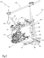
- the figure 1 represents a toroidal winding machine M, allowing the production of wound toroids intended for the production of current measurement sensors.
- a wound toroid comprises a toroidal support and a winding of conductive wire, in particular of copper wire, which is wound around the support.
- the support For the production of such a wound toroid, the support must be driven in rotation about its axis so as to wind the winding wire around its entire circumference.
- the machine M comprises a winding table 100 for supporting and rotating a toroidal support T around its axis and a winding head 200 for performing the winding operation strictly speaking.
- the winding table 100 includes an inclined support 102.
- the winding head 200 comprises a support plate 206, below which are fixed four linear guides 210, of which only two are shown in figure 2 .
- the linear guides 210 make it possible to position the winding head 200 relative to the winding table 100.
- the linear guides 210 are recirculating ball pads giving a high load capacity.
- a brake 208 is interposed between two of the pads 210.
- the brake 208 has an actuating lever.
- An arm 212 extending in the same plane as the support plate 206, carries two sleeves 214 each delimiting an oblong hole through which a pin 216 passes.
- the pin 216 makes it possible to immobilize the winding head 200 in translation with respect to to the winding table 100.
- the winding head 200 also comprises a vertical plate 202, which is perpendicular to the support plate 206 and on which are fixed all the components necessary for the winding of the toroid.
- the vertical plate 202 supports a magazine 220, the function of which is to store the quantity of wire necessary for the winding of a toroid.
- the toroidal winding machine M comprises a system 300 for feeding winding wire from a mother reel (not shown) located behind the machine M to the magazine 220.
- the mother reel is installed on a sliding tray.
- the system 300 comprises several guide components, and in particular a plate 306 delimiting an orifice 308 for passing the wire and two guide members 310 arranged between the plate 306 and a wire cutting system 312, which can be operated manually by means of a lever 314. Finally, the system 300 comprises, at the end of the chain, a roller 316 with a V-shaped groove for guiding the winding wire towards the magazine 220.
- a bracket 302 is also attached to the vertical plate 202.
- the bracket 302 is provided at its end with a hook 304 enabling one end of the winding wire to be attached when the toroid winding sequence is started.
- a counterweight system (not shown) makes it possible to maintain a certain tension at the end of the winding wire. Thanks to this system, the tension value at the end of the wire when starting the winding is repeatable over several sequences, as long as the same counterweight is used. This was not the case in the prior art, where the end of the wire had to be held in the hand by the operator during the winding operation. This repeatability makes it possible to obtain low dispersions with regard to the quality of the winding. Also, the operator's safety is preserved and the risk of accident is reduced.
- the store 220 is annular in shape, centered on an axis X220.
- the magazine 220 does not extend all the way around the axis X220, since there is a permanent opening O220 between the two ends of the magazine 220.
- the store 220 delimits a peripheral groove 222 with a U-shaped section, forming a storage volume for the winding wire.
- the magazine comprises, on one of its sides, a slot 228 in the form of a whistle and / or a hole 229, for attaching one end of the winding wire.
- a slot 228 in the form of a whistle and / or a hole 229, for attaching one end of the winding wire.
- the operator may use the slot 228 or the hole 229 to tie the wire.
- the magazine 220 defines a peripheral rim 226 intended to receive a toothed ring (not shown) and a guide profile in rotation.
- the rotational guide profile is formed by a rib 224, which extends over the entire periphery of the store 220. This is referred to as guidance from the outside.
- the section of the rib 224 is in the shape of a half-moon.
- the winding head 200 comprises a mechanism for driving the magazine 220 in rotation around the axis X220.
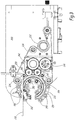
- This mechanism is represented at figure 3 especially. It comprises two drive pinions 240, intended to cooperate with the teeth of the crown of the store.
- the two pinions 240 are driven by a drive wheel 242, having complementary teeth.
- This driving wheel is connected to a first electric motor (not visible in the figures) arranged on the other side of the vertical plate 202.
- a second motor is provided. This second motor drives a toothed wheel 244 which is in mesh with the wheel 242.
- the first and the second motor are controlled in intensity.
- the second motor selectively acts as a brake.
- the first motor is said to be "master”, while the second motor is said to be “slave”.
- This arrangement allows finer regulation of the mechanical tension of the wire during winding. Indeed, it is known that electric motors exhibit at low speed, that is to say at low intensity, an operation which is not optimal. This is due in particular to phenomena of non-linearity.
- the "slave” motor therefore makes it possible to use the optimum operating range of the "master” motor in all circumstances, and in particular even when the required voltage level requires a low motor torque.
- the motorization unit of the store 220 therefore comprises two motors working in differential torque.
- the mechanical principle is based on the 80/20 rule governing the operation of engines.
- a motor has linear torque when used over 80% of its range. Between 0 to 10% and 90 to 100%, the motors present linearity problems. Therefore to have a motor as stable as possible and therefore linear, it must be used at 50% of its capacity. In our case, we want to regulate a voltage between 0 and 300 grams. This is why two engines are planned: one master and the other slave, working in differential torque to generate the tension of the wire by a delta of torque with the motorization of the cursor.
- the master motor (slider) delivers a voltage of 400 grams, the voltage being defined as the product of the slider radius, the engine torque and the motor / slider reduction ratio.
- the slave motor (magazine) will have to generate a counter-force of 220 grams or 41.5% of its scale.
- the two motors work within their comfort range, guaranteeing the most linear result possible.
- the means for guiding the magazine in rotation 220 comprise a series of rotating rollers 250, distributed over the periphery of the magazine 220.
- the rollers 250 define a groove of section complementary to that of the rib 224.
- they are each fitted around a mandrel belonging to a support ring 251, which is split.
- the winding head 200 comprises a cursor 260 for guiding the winding wire, leaving the magazine 220, around the toroid to be wound.
- the cursor 260 is provided to perform a circular path around the section of the toroid to be wound.
- the section of the toroid to be wound it is obviously the section of the torus in a half-plane of which the central axis of the torus can be considered as a generator. In other words, each point of the central axis of the torus is included in this half-plane.
- This section can be circular, oval, rectangular, etc.
- the slider 260 and the magazine 220 are made by 3D printing, in particular in titanium because the titanium has a relatively low density and a very low coefficient of ductility.
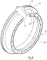
- the cursor 260 is fixed on a load wheel 262, visible in particular at the figure 5 .
- the means for fixing the slider 260 on the wheel 262 include an intermediate fixing part (not shown) and screws.
- this fixing part is optional, in the sense that the cursor 260 could be fixed directly on the wheel 262.
- the wheel 262 is centered on an axis X262 and extends over an angular sector strictly less than 360 °.
- the wheel 262 effectively delimits a permanent opening O262 between its two ends. It comprises a part 264 with teeth and a cylinder 263, intended to be engaged coaxially inside the magazine 220.
- On the side of the cylindrical part 263 are provided orifices 268 for receiving screws (not shown) for fixing the cursor 260.
- the orifices are distributed over the entire curvilinear length of the wheel 262, so as to be able to fix the cursor 260 anywhere.
- the wheel 262 and the magazine 220 each delimit a permanent opening for the passage of the torus is particularly advantageous, and this in particular when the wire breaks during winding.
- the magazine had to be unwound manually and entirely in order to be able to access the removable section and open the magazine. It was very time consuming.
- the permanent openings O220 and O262 respectively of the magazine and of the wheel, when the wire breaks, it is simply necessary, to take out the toroid, to put the openings O220 and O262 at the same level and to cut the amount of wire extending between the two ends of the store.
- the torus can then be extracted quickly by opening the concentric 3-finger forceps (described below) which carries the torus.
- the wheel 262 is guided in rotation by a series of rollers 252 arranged inside the latter.
- the rollers 252 each comprise a groove cooperating with a peripheral rib 266 formed on the internal radial surface of the cylindrical part 263.
- the rib 266 has a section in the form of a half-moon.
- the mechanism for driving the slider 260 in rotation is visible in particular at the figure 3 .
- This mechanism comprises a toothed belt 230 cooperating with the toothed part 264 of the wheel 262.
- the belt 230 is driven by a driving pulley 232.
- Return pulleys 234 are provided to guide the belt 230 as far as the toothed part 264. of the wheel 262.
- the rotating slider 260 driving mechanism is separate from the rotating magazine 220 driving mechanism, so that the magazine 220 and the slider 260 can be rotated independently of each other. This allows, among other things, to precisely adjust the voltage value during winding by modifying the speed differential between the store 220 and the slider 260, the voltage value being all the greater as the speed differential is high.
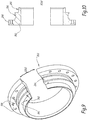
- FIG. 6 a winding head is shown according to a second embodiment of the invention.
- the elements identical or comparable to those of the first embodiment retain their numerical references, while the other elements bear other numerical references. Also, only the differences from the first embodiment are mentioned for the sake of brevity.
- the store 220 is guided in rotation from the inside and driven in rotation from the outside. It includes a guide / drive part 223, which is cylindrical centered on the X220 axis.
- This cylindrical part 223 comprises, on its internal radial surface, a peripheral rib 224, with a sectional profile which is in the example in the shape of a half-moon.
- the store 220 does not include an attached toothed wheel, in the sense that everything is in one piece (in one piece): the cylindrical part 223 has, on its outer radial surface, teeth 221 for driving in rotation.
- Wheel 262 includes a receiving strip 266 for rolling elements (not shown), such as balls or rollers.
- the wheel 262 extends over an angular sector strictly less than 360 °. It delimits an opening O262 for the loading and unloading of the toroid in the center of the store 220.
- the wheel 262 defines at least one orifice 265 for screwing a toothed wheel (not visible in the figures) intended to cooperate with a toothed belt comparable to that of the first embodiment.
- the toothed wheel is intended to be mounted on a cylindrical rim 261 of the wheel 262.
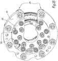
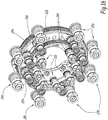
- This third embodiment relates to the components used for guiding the magazine 220 and the carrying wheel 262 of the slider 260, the objective being to provide optimum means of guiding in rotation, despite the presence of the zones of 'permanent opening provided in the store 220 and in the carrier wheel 262.
- the idea is to ensure guiding of the parts both from the inside and from the outside.
- This principle has a name: it is feedback guidance.
- the means for guiding the magazine in rotation include so-called “outer” rollers 250, which are advantageously eight in number and which are distributed over the periphery around the magazine, and so-called “inner” rollers 254, which are also provided in number of eight and which are distributed on the interior perimeter of the store.
- rollers 254 also form part of the means for guiding in rotation the wheel 262 carrying the slider 260.
- These means also include rollers 256, called “internal” rollers, which are advantageously 8 in number and which are distributed over the perimeter. inside of load wheel 262.
- rollers 254 and 256 are supported by the same flange 255, also having a permanent opening, comparable to the openings O220 and O262.
- each roller is mounted on an eccentric. This means that each roller can be moved radially over a certain stroke and therefore that the guide diameter of the rollers is adjustable.
- winding table 100 is also clearly distinguished from the state of the art.
- the winding table comprises a system of polyurethane rollers, which have both a rotary drive function and a guide function.
- Each roller is mounted on a vertical cylinder, which is fixed to one end of an articulated connecting rod.
- each roller defines a peripheral C-shaped groove to receive the torus.
- the position of the rollers is adjustable in height. Only two of the three rollers are mounted on motorized cylinders, that is to say rotating.
- the third roller which therefore has a guiding function only, has an additional degree of freedom, which is a displacement in translation.
- This third roller acts as a pressure roller. It is moved during the stages of loading the bare toroid and unloading the wound toroid.
- a major drawback of this winding table lies in the difficulty in maintaining the concentricity (or coaxiality) during a change in toroid diameter.
- this operation is carried out manually by moving the rollers one by one and can take up to several hours, for a result often approximate.
- the centering dispersions of the toroids lead to disparities in the quality of the winding, that is to say the toroids with a variable winding pitch from one toroid to another.
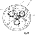
- the winding table 100 belonging to the toroidal winding machine M, comprises means 110 for supporting and guiding the toroid T in rotation and means 120, 120 'for driving the toroid T in rotation which are distinct from the means guide 110.
- the support and guide means 110 are formed by a concentric gripping clamp. This clamp is supported by feet 104 extending from the support 102.
- the concentric gripper 110 comprises three rollers 118 arranged so that each roller 118 remains permanently equidistant from the other two rollers and from a central axis Z110. It is commonly referred to as a "concentric three finger clamp”.
- each roller 118 is mounted on a cylinder 116 fixed eccentrically on a rotary pinion 112.
- Each roller 118 comprises a hollow part substantially V-shaped to receive the torus T. This hollow part, which extends, at the bottom.
- This symmetrical groove profile makes it possible to automatically center the torus T inside the concentric clamp 110, and therefore to prevent the torus from positioning itself crosswise between the three rollers 118.
- all the rotary pinions 112 are meshed with a central pinion 114, movable around the axis Z110.
- the Z110 axis coincides with the central axis of the toroid when the toroid is positioned inside the clamp.
- the rotation of the central pinion 114 causes the rotation of each pinion 112, and therefore the movement of the rollers 118 relative to each other.
- the construction of this clamp 110 is such that the rollers 118 automatically remain equidistant from each other when the central pinion 114 is turned.
- a lever 111 allows the central pinion 114 to be pivoted to more or less open the clamp. .
- the three rollers 118 are movable between a minimum open position and a maximum open position and are returned to the open position. minimum thanks to a counterweight system (not shown) acting on the central pinion 114.
- a closing stopper 115 is provided to limit the closing of the clamp 110. Otherwise, the stopper 115 defines a minimum opening (or maximum closing) configuration, in which the rollers 118 are placed as close as possible to central axis Z110.
- the counterweight system comprises a cable (not shown), preferably made of steel, which is wound around the central pinion 114 and which is guided around one or more return pulleys (not shown) so as to be attached to a pig (not shown) serving as a counterweight.
- This counterweight has the advantage of generating equivalent radial forces at the level of the three rollers 118 throughout the winding cycle.
- the pig is formed by a threaded rod comprising a hook for attaching to the cable and by at least one weight screwed around the rod.
- the mass of the pig is advantageously adjusted during the winding cycle so as to open the clamp 110 and compensate for the increase in the cross section of the torus (due to the winding of the winding wire).
- the weight is adjusted by adding steel plates calibrated at 50g unit or 1kg unit.
- the means for driving the torus T in rotation comprise at least two clamps 120 and 120 ', the two clamps 120 and 120' being movable in rotation in a respective angular sector defined between two rollers 118, so as to be able to grip and moving in turn the torus to be wound T over a stroke proportional to the angular spacing between two rollers.
- the clamps 120 and 120 ' can be qualified as "perimeter clamps”.
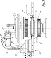
- Each of the grippers 120 and 120 ' is driven in rotation around an axis Z120 by an independent pulley-belt system, part of which is visible at the figure 11 .
- the axis of rotation Z120 of the clamps 120 and 120 ' coincides with the central axis Z110 of the three-finger clamp, and with the axis of the torus when the latter is positioned inside the clamp 110.
- the axis of rotation of the torus T coincides with the Z110 and Z120 axes.
- the gripper drive system 120 includes an electric motor 140, a pulley 141, and a toothed belt 142.
- the motor 140 drives the pulley 141 and the pulley 142, which is driving, transmits a mechanical torque to a driven pulley 124 (visible at figure 13 ) via the toothed belt 142.
- the gripper 120 ′ has its own drive system, which is substantially identical to that of the gripper 120. It comprises an electric motor 140 ′, a driving pulley 141 'and a toothed belt 142'. Motor 140 'transmits torque to pulley 141', which is transmitted to a driven pulley 124 'via belt 142'. The axis of rotation of the pulleys 124 and 124 'coincides with the axis Z120.
- An epicyclic reduction gear and a roller bearing are arranged at the output of each motor 140 and 140 'so as to absorb the radial forces (centrifugal forces).
- the gripper 120 comprises what is called a racket 122, which is integral in rotation with the pulley 124.
- the racket 122 supports a linear actuator 128, of the electric jack type, comprising a fixed part and a movable part.
- the movable part of the jack can be moved in a radial direction with respect to the axis Z120.
- a gooseneck-shaped part 126 is mounted on the movable part of the linear actuator 128.
- This gooseneck part 126 carries an electric gripper with parallel jaws equipped with two jaws 121 adapted to the geometry of the torus to be wound T
- the jaws 121 are parallel and are movable towards each other, so as to be able to grip tori of different sizes.
- a micrometric table 127 serving as a mechanical interface between the gooseneck-shaped part 126 and the jaws 121, makes it possible to adjust the height position of the jaws 121.
- the winding table includes a system for controlling the angular position of the toroid during the winding operation.
- This system comprises in the example a measuring means in the form of an incremental rotary encoder 125, which is advantageously mounted directly around the central shaft (not shown) integral with the rackets 122 and 122 '.
- the encoder is interposed between the rackets 122 and 122 ′ to guarantee the highest level of precision.
- the movement of the grippers 120 and 120 ′ is controlled by a dedicated processor, capable of managing the angular displacement of the grippers (starting position, end-of-stroke position, angular speed, etc.) and the opening and closing sequences of the grippers. bites 121.
- the section of the toroid to be wound is advantageously positioned in the center of the magazine 220.
- the winding table 200 therefore comprises two rails 130, which are profiled rails with recirculating balls and high load capacity. These rails 130 are configured for guiding the pads 210 of the winding head 200.
- the depth adjustment means 130 are configured to move the winding head 100 in a plane radial to the axis Z120 or Z110 of rotation of the torus T. This has the advantage that the wire is deposited in this same radial plane, and therefore that the turns are well parallel to each other.
- the fact of being able to move back the winding head 200 relative to the winding table 100 also makes it possible to intervene more easily on the components of the head 200 during maintenance operations and also when certain adjustments have to be made. mechanical.
- the machine M is designed for winding three toroids of different diameters. Alternatively, this could be designed for a larger diameter number.
- the winding table 100 includes an indexing device 132, visible only at the figure 11 , and making it possible to ensure precise positioning of the winding head 200 in three positions. This indexing device 132 delimits three housing for positioning the pin 216. Locking the pin 216 in one of the three housings determines the axial position of the winding head 200 along the rails 130.
- the indexing device 132 is provided with pin detection sensors. There is a detection sensor for each housing. These sensors provide feedback on the position of the winding head 200 with respect to the table 100 which has been selected.
- the winding of a toroid is performed as follows.
- Magazine 220 is advanced until the center of magazine 220 is positioned precisely around a section of the torus.
- a torus (bare) to be wound is positioned inside the concentric clamp 110, and in particular between the three rollers 118 of the clamp. For this, the operator can move the winding head along the rails 130, until reaching the position corresponding to the diameter of the selected torus.
- the store 220 is then loaded with the quantity of wire necessary for winding the toroid.
- the winding wire is pulled using the system 300 from a mother coil, in particular a coil of copper wire.
- One end of the winding wire is then attached to the magazine, eg, hole 229 or whistle-shaped slot 228, and the magazine is rotated.
- the number of turns made by the store can advantageously be programmed as a function of the diameter of the toroid to be wound. It can also be calculated with respect to the number of turns to be wound.
- the winding wire is stored in the U-shaped groove 222. As soon as the quantity of wire necessary for winding has been loaded, the rotation of the magazine 220 is interrupted and the operator cuts the wire, in particular thanks to the wire cutting system 312. The loading phase is finished.
- the operator passes the wire through the guide channel of the cursor, then he performs a few dead turns around an element of the toroid to be wound, this element possibly being a spindle (not shown) or a section of the toroid.
- the wire is introduced inside the wire guide system 218 and the end of the wire is hooked to the hook 304 of the hanger system 302.
- a ballast (not shown) is assembled on the system 302 so as to put the weight. winding wire under tension. In the absence of a spindle, the starting wire is kept taut towards the rear of the machine. Winding starts and after about ten turns, the operator can bring the wire back to the hanger hook and attach the counterweight to it.
- the winding process can then begin.
- the operator programs the characteristics related to the winding sequence, such as the desired voltage level, the winding pitch, etc.
- the slider is rotated around the section of the toroid to be wound and pulls the wire stored inside the magazine.
- the magazine is then also driven in rotation by the consumption of yarn produced, but at a slower speed.
- the rotation of the cursor gradually causes the winding of the copper wire around the section of the toroid to be wound.
- the torus In parallel, the torus is moved in rotation around its axis, in a manner synchronized with the rotation of the cursor.
- the clamps 120 and 120 ′ take turns to grasp the torus to move it in rotation over an angular sector corresponding substantially to the angle between two rollers 118, ie 120 °.
- the stroke of the grippers 120 and 120 ' is all the greater as the diameter of the torus is high.
- One or more layers of wires can be applied around the torus.
- the torus can make a complete revolution.
- a programmed segment can correspond to a layer or a part of the layer (it may be necessary to break down a layer into several segments when, for example, we want to generate a different winding density on the beginning or the end of the layer, that is, that is, very locally).
- Each segment is defined by the direction of rotation of the torus, the winding pitch used, the number of turns, speed, acceleration (and deceleration), winding voltage and a stop (machine stop), for example at the end of the segment.
- the parameters of each segment can therefore be modified as desired, which offers a certain programming flexibility.
- the toothed belt 230 is replaced by one or more drive pinions.
- the slider driving mechanism 260 could include two small pinions, each interposed between two rollers 254. A removable engine block could then be used to drive the pinions.
- the number of rollers of the concentric clamp 110 may be greater than 3.
Landscapes
- Engineering & Computer Science (AREA)
- Power Engineering (AREA)
- Manufacturing & Machinery (AREA)
- Physics & Mathematics (AREA)
- General Physics & Mathematics (AREA)
- Storage Of Web-Like Or Filamentary Materials (AREA)
- Winding Filamentary Materials (AREA)
- Manufacturing Cores, Coils, And Magnets (AREA)
Claims (8)
- Ringbewickelmaschine, die einen Wickelkopf (200) und einen Wickeltisch (100) umfasst, der ausgebildet ist, einen Torus (T) bei einer Wickelsequenz zu lagern und in Drehung zu versetzen, wobei der Wickelkopf umfasst:- ein ringförmiges Magazin (220), um eine für das Wickeln eines Torus notwendige Drahtmenge zu bevorraten,- einen ersten Mechanismus (240, 242, 244) zum Antreiben des Magazins zur Drehung und- einen Schieber (62), um am Ausgang des Magazins den Draht um den Torus herum zu führen,wobei der Wickelkopf einen zweiten Mechanismus (230, 232, 234), unterschiedlich zum ersten Mechanismus, zum Antreiben des Schieber zur Drehung umfasst, derart, dass das Magazin und der Schieber zur Drehung unabhängig voneinander angetrieben werden können, dadurch gekennzeichnet, dass der Schieber (260) an einer Seitenwand eines Rades (262) befestigt ist, das koaxial im Inneren des Magazins montiert ist.
- Maschine nach Anspruch 1, dadurch gekennzeichnet, dass der Wickeltisch erste Mittel (110) zum Abstützen und Führen des Torus (T) zur Drehung und zweite Mittel (120, 120') zum Antreiben des Torus (T) zur Drehung, unterschiedlich zu den ersten Mitteln, umfasst und dass die ersten Mittel (110) durch eine konzentrischen Greiferzange gebildet werden.
- Maschine nach Anspruch 2, dadurch kennzeichnet, dass eine Drehachse des Torus (T) mit einer Mittelachse (Z110) der konzentrischen Greiferzange (110) übereinstimmt.
- Maschine nach einem der vorhergehenden Ansprüche, dadurch gekennzeichnet, dass der Wickeltisch (100) Mittel (130) zum Einstellen des Wickelkopfes (200) hinsichtlich der Tiefe umfasst.
- Maschine nach Anspruch 4, dadurch gekennzeichnet, dass die Mittel (130) zur Tiefeneinstellung ausgebildet sind, den Wickelkopf (100) in einer Ebene radial zu einer Drehachse (Z120, Z110) des Torus (T) zu bewegen.
- Maschine nach einem der vorhergehenden Ansprüche, dadurch gekennzeichnet, dass das Magazin (220) und das Rad (262) auf eine selbe Achse zentriert sind und sich über einen Winkelsektor kleiner als 360° erstrecken und so eine ständige Öffnung (O220, O262) für den Durchgang des Torus definieren.
- Maschine nach einem der vorhergehenden Ansprüche, dadurch gekennzeichnet, dass sie erste Mittel (250; 250, 254) zum Führen des Magazins zur Drehung und zweite Mittel (252; 254, 256) zum Führen, unterschiedlich zu den ersten Mitteln zum Führen, um die Drehung des Schiebers zu führen, umfasst.
- Verfahren zum Wickeln eines Torus (T) mittels einer Maschine nach Anspruch 2, wobei das Verfahren die Schritte umfasst, die darin bestehena) Positionieren des Torus (T) innerhalb der konzentrischen Greiferzange,b) Bewegen des Wickelkopfes (200) bis eine Position erreicht ist, in der ein Abschnitt des zu bewickelnden Torus im Wesentlichen in der Mitte eines von dem Schieber (260) beschriebenen Kreises angeordnet ist,c) Benutzen der zweiten Mittel zum Antreiben des Torus (T), um den Torus zu drehen, undd) Versetzen des Magazins (220) und den Schieber (260) in Drehung um den Abschnitt des Torus, um den im Magazin bevorrateten Draht um den Abschnitt des Torus herum abzuwickeln.
Applications Claiming Priority (1)
| Application Number | Priority Date | Filing Date | Title |
|---|---|---|---|
| FR1752997A FR3064991B1 (fr) | 2017-04-06 | 2017-04-06 | Tete de bobinage pour une machine de bobinage toroidal, machine de bobinage toroidal comprenant une telle tete de bobinage et procede |
Publications (2)
| Publication Number | Publication Date |
|---|---|
| EP3385965A1 EP3385965A1 (de) | 2018-10-10 |
| EP3385965B1 true EP3385965B1 (de) | 2020-08-05 |
Family
ID=58993098
Family Applications (1)
| Application Number | Title | Priority Date | Filing Date |
|---|---|---|---|
| EP18165815.4A Active EP3385965B1 (de) | 2017-04-06 | 2018-04-05 | Wicklungs-kopf für eine toroidal-wickelmaschine, toroidal-wickelmaschine bestehend aus solchem wicklungs-kopf und prozess |
Country Status (4)
| Country | Link |
|---|---|
| US (1) | US10882714B2 (de) |
| EP (1) | EP3385965B1 (de) |
| CN (1) | CN108695057B (de) |
| FR (1) | FR3064991B1 (de) |
Families Citing this family (10)
| Publication number | Priority date | Publication date | Assignee | Title |
|---|---|---|---|---|
| CN111640573B (zh) * | 2020-05-09 | 2021-10-15 | 北京华强诚信电器有限公司 | 一种互感器缠绕装置 |
| CN111710524A (zh) * | 2020-07-28 | 2020-09-25 | 珠海市恒诺科技有限公司 | 一种排线组件及绕线机 |
| CN112338450B (zh) * | 2020-10-23 | 2022-05-06 | 漳州市永良针纺机械有限公司 | 一种高精密中心组智能化成型工艺 |
| CN112276493B (zh) * | 2020-10-23 | 2022-05-06 | 漳州市永良针纺机械有限公司 | 一种圆纬机配件环保铸造加工工艺 |
| CN112338449B (zh) * | 2020-10-23 | 2022-05-06 | 漳州市永良针纺机械有限公司 | 一种高精密中心组节能智能制造方法 |
| CN112404893B (zh) * | 2020-10-23 | 2022-04-01 | 漳州市永良针纺机械有限公司 | 一种环保节能圆纬机配件铸造工艺 |
| CN114137456A (zh) * | 2021-11-30 | 2022-03-04 | 西部超导材料科技股份有限公司 | 一种超导线材临界电流测试用样品骨架的绕制装置及绕制方法 |
| CN117267460B (zh) * | 2023-11-17 | 2024-02-02 | 山西美锦氢能开发有限公司 | 一种低温管件密封保护结构辅助安装装置 |
| CN118942889B (zh) * | 2024-09-29 | 2025-09-05 | 北京电科能创技术有限公司 | 一种干式空心电抗器辅助生产装置 |
| CN118969504B (zh) * | 2024-10-16 | 2025-04-04 | 河南汇众机电设备有限公司 | 一种互感器自动绕线装置 |
Family Cites Families (22)
| Publication number | Priority date | Publication date | Assignee | Title |
|---|---|---|---|---|
| US263780A (en) * | 1882-09-05 | haase | ||
| US302627A (en) * | 1884-07-29 | espeut | ||
| US700713A (en) * | 1901-01-08 | 1902-05-20 | Wright And Colton Wire Cloth Company | Machine for covering coils of wire. |
| US802359A (en) * | 1904-04-27 | 1905-10-17 | Western Electric Co | Winding-machine. |
| US2331674A (en) * | 1940-05-29 | 1943-10-12 | Fox Paul Xavier | Coil winding machine |
| US2437309A (en) * | 1944-05-22 | 1948-03-09 | Chicago Telephone Supply Co | Toroidal winding machine |
| GB820798A (en) * | 1955-03-08 | 1959-09-23 | Micafil Ltd | Improvements in or relating to devices for winding annular bodies with wire |
| US3383059A (en) * | 1965-03-22 | 1968-05-14 | Universal Mfg Co | Toroidal coil winding machine |
| US3412948A (en) * | 1965-08-31 | 1968-11-26 | Universal Mfg Company Inc | Toroidal coil winding machine wire guide |
| US3559899A (en) * | 1969-02-24 | 1971-02-02 | Universal Mfg Co | Toroidal coil-winding machine for deflection yoke coils for television picture tubes and the like |
| DE2940987A1 (en) * | 1978-03-15 | 1981-01-15 | J Pedersen | A winding unit for use in a winding machine for winding elongate members or cores |
| CA1192281A (en) * | 1982-01-06 | 1985-08-20 | John L. Fisher | Toroidal electrical transformer and method of producing same |
| US4637563A (en) * | 1984-02-14 | 1987-01-20 | Daihen Corporation | Toroidal winding apparatus |
| MX161871A (es) * | 1985-02-06 | 1991-02-07 | Kuhlman Corp | Mejoras a maquina electromecanica para fabricar el embobinado de bajo voltaje para un transformador toroidal |
| US4884758A (en) * | 1985-02-06 | 1989-12-05 | Kuhlman Corporation | Self-loading wire winding assembly and method |
| US4771957A (en) * | 1985-02-06 | 1988-09-20 | Kuhlman Corporation | Apparatus and method for fabricating a low voltage winding for a toroidal transformer |
| US4917318A (en) * | 1985-02-06 | 1990-04-17 | Kuhlman Corporation | Apparatus for fabricating a low voltage winding for a toroidal transformer |
| US20010015393A1 (en) * | 1998-02-24 | 2001-08-23 | Hiroshi Miyazaki | Winding apparatus |
| WO2004021377A1 (ja) * | 2002-08-28 | 2004-03-11 | Tanaka Seiki Co., Ltd. | 矩形断面線材の巻線装置 |
| US20050279265A1 (en) * | 2004-03-09 | 2005-12-22 | Chih-I Chien | Wire-guiding structure of a shuttle of a sewing machine |
| KR101118857B1 (ko) * | 2006-05-26 | 2012-03-19 | 닛또꾸 엔지니어링 가부시키가이샤 | 권선 장치, 텐션 장치 및 권선 방법 |
| EP2953149B1 (de) * | 2014-06-06 | 2017-04-19 | RUFF GmbH | Vorrichtung und Verfahren zum magazinlosen Bewickeln von Ringkernen |
-
2017
- 2017-04-06 FR FR1752997A patent/FR3064991B1/fr not_active Expired - Fee Related
-
2018
- 2018-02-13 US US15/895,347 patent/US10882714B2/en active Active
- 2018-04-04 CN CN201810301465.9A patent/CN108695057B/zh active Active
- 2018-04-05 EP EP18165815.4A patent/EP3385965B1/de active Active
Non-Patent Citations (1)
| Title |
|---|
| None * |
Also Published As
| Publication number | Publication date |
|---|---|
| FR3064991B1 (fr) | 2019-08-16 |
| CN108695057A (zh) | 2018-10-23 |
| US10882714B2 (en) | 2021-01-05 |
| CN108695057B (zh) | 2021-09-17 |
| EP3385965A1 (de) | 2018-10-10 |
| US20180290857A1 (en) | 2018-10-11 |
| FR3064991A1 (fr) | 2018-10-12 |
Similar Documents
| Publication | Publication Date | Title |
|---|---|---|
| EP3385965B1 (de) | Wicklungs-kopf für eine toroidal-wickelmaschine, toroidal-wickelmaschine bestehend aus solchem wicklungs-kopf und prozess | |
| EP0248301B1 (de) | Verfahren und Vorrichtung zur Herstellung von Verstärkungen für Reifen | |
| FR2503115A1 (fr) | Procede et dispositif pour amener un fil d'une bobine de stockage, notamment un fil de machine d'electroerosion | |
| FR2694519A1 (fr) | Procédé de fabrication d'un pneumatique et machine de fabrication d'un renfort de sommet pour pneumatique. | |
| EP0281511B1 (de) | Drahtschneidevorrichtung | |
| FR2533544A1 (fr) | Procede et machine pour la production de l'enroulement d'une bobine croisee | |
| CH371373A (fr) | Machine pour enrouler un élément filiforme sur une bobine | |
| CH618660A5 (de) | ||
| EP0211387B1 (de) | Vorrichtung und Verfahren zum Vereinigen von Fäden, Fäden, die mit dieser Vorrichtung und nach diesem Verfahren hergestellt sind | |
| BE1011429A3 (fr) | Metier a tricoter circulaire. | |
| CH684336A5 (fr) | Bobineuse. | |
| CA1054588A (fr) | Procede et machine d'enroulement de bandes sur un corps cylindrique | |
| WO1982004421A1 (fr) | Procede et dispositif pour enfiler des rayons sur un moyeu de roue a rayons | |
| WO2007012476A1 (fr) | Enfuteur pour fil metallique | |
| WO2018167021A1 (fr) | Laminoir multimandrin, méthode de réglage de la position des mandrins d'un tel laminoir et procédé de laminage en continu au moyen d'un tel laminoir | |
| EP3275581A1 (de) | Rotierendes schneidwerkzeug für maschine zur herstellung von verpackungen, und verfahren, bei dem dieses schneidwerkzeug zum einsatz kommt | |
| FR2865722A1 (fr) | Dispositif d'enroulement a deux rouleaux d'entrainement pour machine a enrouler en continu et procede d'enroulement avec regulation de l'effort d'application des rouleaux d'entrainement | |
| WO2021074529A1 (fr) | Faisceau de fibres optiques | |
| CH303999A (fr) | Machine à renvider. | |
| CH337104A (fr) | Machine pour câbler des fils | |
| CH714626A2 (fr) | Porte-outils et machine de tournage inversé comportant un tel porte-outils. | |
| FR2499054A1 (fr) | Mecanisme d'entrainement lineaire d'un cable | |
| BE464627A (de) | ||
| BE554224A (de) | ||
| BE515313A (de) |
Legal Events
| Date | Code | Title | Description |
|---|---|---|---|
| PUAI | Public reference made under article 153(3) epc to a published international application that has entered the european phase |
Free format text: ORIGINAL CODE: 0009012 |
|
| STAA | Information on the status of an ep patent application or granted ep patent |
Free format text: STATUS: THE APPLICATION HAS BEEN PUBLISHED |
|
| AK | Designated contracting states |
Kind code of ref document: A1 Designated state(s): AL AT BE BG CH CY CZ DE DK EE ES FI FR GB GR HR HU IE IS IT LI LT LU LV MC MK MT NL NO PL PT RO RS SE SI SK SM TR |
|
| AX | Request for extension of the european patent |
Extension state: BA ME |
|
| STAA | Information on the status of an ep patent application or granted ep patent |
Free format text: STATUS: REQUEST FOR EXAMINATION WAS MADE |
|
| 17P | Request for examination filed |
Effective date: 20190319 |
|
| RBV | Designated contracting states (corrected) |
Designated state(s): AL AT BE BG CH CY CZ DE DK EE ES FI FR GB GR HR HU IE IS IT LI LT LU LV MC MK MT NL NO PL PT RO RS SE SI SK SM TR |
|
| GRAP | Despatch of communication of intention to grant a patent |
Free format text: ORIGINAL CODE: EPIDOSNIGR1 |
|
| STAA | Information on the status of an ep patent application or granted ep patent |
Free format text: STATUS: GRANT OF PATENT IS INTENDED |
|
| INTG | Intention to grant announced |
Effective date: 20200303 |
|
| GRAS | Grant fee paid |
Free format text: ORIGINAL CODE: EPIDOSNIGR3 |
|
| GRAA | (expected) grant |
Free format text: ORIGINAL CODE: 0009210 |
|
| STAA | Information on the status of an ep patent application or granted ep patent |
Free format text: STATUS: THE PATENT HAS BEEN GRANTED |
|
| AK | Designated contracting states |
Kind code of ref document: B1 Designated state(s): AL AT BE BG CH CY CZ DE DK EE ES FI FR GB GR HR HU IE IS IT LI LT LU LV MC MK MT NL NO PL PT RO RS SE SI SK SM TR |
|
| REG | Reference to a national code |
Ref country code: GB Ref legal event code: FG4D Free format text: NOT ENGLISH |
|
| REG | Reference to a national code |
Ref country code: CH Ref legal event code: EP |
|
| REG | Reference to a national code |
Ref country code: AT Ref legal event code: REF Ref document number: 1299866 Country of ref document: AT Kind code of ref document: T Effective date: 20200815 |
|
| REG | Reference to a national code |
Ref country code: DE Ref legal event code: R096 Ref document number: 602018006551 Country of ref document: DE |
|
| REG | Reference to a national code |
Ref country code: IE Ref legal event code: FG4D Free format text: LANGUAGE OF EP DOCUMENT: FRENCH |
|
| REG | Reference to a national code |
Ref country code: LT Ref legal event code: MG4D |
|
| REG | Reference to a national code |
Ref country code: NL Ref legal event code: MP Effective date: 20200805 |
|
| REG | Reference to a national code |
Ref country code: AT Ref legal event code: MK05 Ref document number: 1299866 Country of ref document: AT Kind code of ref document: T Effective date: 20200805 |
|
| PG25 | Lapsed in a contracting state [announced via postgrant information from national office to epo] |
Ref country code: SE Free format text: LAPSE BECAUSE OF FAILURE TO SUBMIT A TRANSLATION OF THE DESCRIPTION OR TO PAY THE FEE WITHIN THE PRESCRIBED TIME-LIMIT Effective date: 20200805 Ref country code: BG Free format text: LAPSE BECAUSE OF FAILURE TO SUBMIT A TRANSLATION OF THE DESCRIPTION OR TO PAY THE FEE WITHIN THE PRESCRIBED TIME-LIMIT Effective date: 20201105 Ref country code: AT Free format text: LAPSE BECAUSE OF FAILURE TO SUBMIT A TRANSLATION OF THE DESCRIPTION OR TO PAY THE FEE WITHIN THE PRESCRIBED TIME-LIMIT Effective date: 20200805 Ref country code: NO Free format text: LAPSE BECAUSE OF FAILURE TO SUBMIT A TRANSLATION OF THE DESCRIPTION OR TO PAY THE FEE WITHIN THE PRESCRIBED TIME-LIMIT Effective date: 20201105 Ref country code: HR Free format text: LAPSE BECAUSE OF FAILURE TO SUBMIT A TRANSLATION OF THE DESCRIPTION OR TO PAY THE FEE WITHIN THE PRESCRIBED TIME-LIMIT Effective date: 20200805 Ref country code: FI Free format text: LAPSE BECAUSE OF FAILURE TO SUBMIT A TRANSLATION OF THE DESCRIPTION OR TO PAY THE FEE WITHIN THE PRESCRIBED TIME-LIMIT Effective date: 20200805 Ref country code: GR Free format text: LAPSE BECAUSE OF FAILURE TO SUBMIT A TRANSLATION OF THE DESCRIPTION OR TO PAY THE FEE WITHIN THE PRESCRIBED TIME-LIMIT Effective date: 20201106 Ref country code: PT Free format text: LAPSE BECAUSE OF FAILURE TO SUBMIT A TRANSLATION OF THE DESCRIPTION OR TO PAY THE FEE WITHIN THE PRESCRIBED TIME-LIMIT Effective date: 20201207 Ref country code: ES Free format text: LAPSE BECAUSE OF FAILURE TO SUBMIT A TRANSLATION OF THE DESCRIPTION OR TO PAY THE FEE WITHIN THE PRESCRIBED TIME-LIMIT Effective date: 20200805 Ref country code: LT Free format text: LAPSE BECAUSE OF FAILURE TO SUBMIT A TRANSLATION OF THE DESCRIPTION OR TO PAY THE FEE WITHIN THE PRESCRIBED TIME-LIMIT Effective date: 20200805 |
|
| PG25 | Lapsed in a contracting state [announced via postgrant information from national office to epo] |
Ref country code: NL Free format text: LAPSE BECAUSE OF FAILURE TO SUBMIT A TRANSLATION OF THE DESCRIPTION OR TO PAY THE FEE WITHIN THE PRESCRIBED TIME-LIMIT Effective date: 20200805 Ref country code: LV Free format text: LAPSE BECAUSE OF FAILURE TO SUBMIT A TRANSLATION OF THE DESCRIPTION OR TO PAY THE FEE WITHIN THE PRESCRIBED TIME-LIMIT Effective date: 20200805 Ref country code: PL Free format text: LAPSE BECAUSE OF FAILURE TO SUBMIT A TRANSLATION OF THE DESCRIPTION OR TO PAY THE FEE WITHIN THE PRESCRIBED TIME-LIMIT Effective date: 20200805 Ref country code: RS Free format text: LAPSE BECAUSE OF FAILURE TO SUBMIT A TRANSLATION OF THE DESCRIPTION OR TO PAY THE FEE WITHIN THE PRESCRIBED TIME-LIMIT Effective date: 20200805 Ref country code: IS Free format text: LAPSE BECAUSE OF FAILURE TO SUBMIT A TRANSLATION OF THE DESCRIPTION OR TO PAY THE FEE WITHIN THE PRESCRIBED TIME-LIMIT Effective date: 20201205 |
|
| PG25 | Lapsed in a contracting state [announced via postgrant information from national office to epo] |
Ref country code: RO Free format text: LAPSE BECAUSE OF FAILURE TO SUBMIT A TRANSLATION OF THE DESCRIPTION OR TO PAY THE FEE WITHIN THE PRESCRIBED TIME-LIMIT Effective date: 20200805 Ref country code: DK Free format text: LAPSE BECAUSE OF FAILURE TO SUBMIT A TRANSLATION OF THE DESCRIPTION OR TO PAY THE FEE WITHIN THE PRESCRIBED TIME-LIMIT Effective date: 20200805 Ref country code: EE Free format text: LAPSE BECAUSE OF FAILURE TO SUBMIT A TRANSLATION OF THE DESCRIPTION OR TO PAY THE FEE WITHIN THE PRESCRIBED TIME-LIMIT Effective date: 20200805 Ref country code: SM Free format text: LAPSE BECAUSE OF FAILURE TO SUBMIT A TRANSLATION OF THE DESCRIPTION OR TO PAY THE FEE WITHIN THE PRESCRIBED TIME-LIMIT Effective date: 20200805 |
|
| REG | Reference to a national code |
Ref country code: DE Ref legal event code: R097 Ref document number: 602018006551 Country of ref document: DE |
|
| PG25 | Lapsed in a contracting state [announced via postgrant information from national office to epo] |
Ref country code: AL Free format text: LAPSE BECAUSE OF FAILURE TO SUBMIT A TRANSLATION OF THE DESCRIPTION OR TO PAY THE FEE WITHIN THE PRESCRIBED TIME-LIMIT Effective date: 20200805 |
|
| PLBE | No opposition filed within time limit |
Free format text: ORIGINAL CODE: 0009261 |
|
| STAA | Information on the status of an ep patent application or granted ep patent |
Free format text: STATUS: NO OPPOSITION FILED WITHIN TIME LIMIT |
|
| PG25 | Lapsed in a contracting state [announced via postgrant information from national office to epo] |
Ref country code: SK Free format text: LAPSE BECAUSE OF FAILURE TO SUBMIT A TRANSLATION OF THE DESCRIPTION OR TO PAY THE FEE WITHIN THE PRESCRIBED TIME-LIMIT Effective date: 20200805 |
|
| 26N | No opposition filed |
Effective date: 20210507 |
|
| PG25 | Lapsed in a contracting state [announced via postgrant information from national office to epo] |
Ref country code: SI Free format text: LAPSE BECAUSE OF FAILURE TO SUBMIT A TRANSLATION OF THE DESCRIPTION OR TO PAY THE FEE WITHIN THE PRESCRIBED TIME-LIMIT Effective date: 20200805 |
|
| PG25 | Lapsed in a contracting state [announced via postgrant information from national office to epo] |
Ref country code: MC Free format text: LAPSE BECAUSE OF FAILURE TO SUBMIT A TRANSLATION OF THE DESCRIPTION OR TO PAY THE FEE WITHIN THE PRESCRIBED TIME-LIMIT Effective date: 20200805 |
|
| PG25 | Lapsed in a contracting state [announced via postgrant information from national office to epo] |
Ref country code: LU Free format text: LAPSE BECAUSE OF NON-PAYMENT OF DUE FEES Effective date: 20210405 |
|
| REG | Reference to a national code |
Ref country code: BE Ref legal event code: MM Effective date: 20210430 |
|
| PG25 | Lapsed in a contracting state [announced via postgrant information from national office to epo] |
Ref country code: LI Free format text: LAPSE BECAUSE OF NON-PAYMENT OF DUE FEES Effective date: 20210430 Ref country code: CH Free format text: LAPSE BECAUSE OF NON-PAYMENT OF DUE FEES Effective date: 20210430 |
|
| PG25 | Lapsed in a contracting state [announced via postgrant information from national office to epo] |
Ref country code: IE Free format text: LAPSE BECAUSE OF NON-PAYMENT OF DUE FEES Effective date: 20210405 |
|
| PG25 | Lapsed in a contracting state [announced via postgrant information from national office to epo] |
Ref country code: IS Free format text: LAPSE BECAUSE OF FAILURE TO SUBMIT A TRANSLATION OF THE DESCRIPTION OR TO PAY THE FEE WITHIN THE PRESCRIBED TIME-LIMIT Effective date: 20201205 |
|
| PG25 | Lapsed in a contracting state [announced via postgrant information from national office to epo] |
Ref country code: BE Free format text: LAPSE BECAUSE OF NON-PAYMENT OF DUE FEES Effective date: 20210430 |
|
| PG25 | Lapsed in a contracting state [announced via postgrant information from national office to epo] |
Ref country code: CY Free format text: LAPSE BECAUSE OF FAILURE TO SUBMIT A TRANSLATION OF THE DESCRIPTION OR TO PAY THE FEE WITHIN THE PRESCRIBED TIME-LIMIT Effective date: 20200805 |
|
| PG25 | Lapsed in a contracting state [announced via postgrant information from national office to epo] |
Ref country code: HU Free format text: LAPSE BECAUSE OF FAILURE TO SUBMIT A TRANSLATION OF THE DESCRIPTION OR TO PAY THE FEE WITHIN THE PRESCRIBED TIME-LIMIT; INVALID AB INITIO Effective date: 20180405 |
|
| PG25 | Lapsed in a contracting state [announced via postgrant information from national office to epo] |
Ref country code: MK Free format text: LAPSE BECAUSE OF FAILURE TO SUBMIT A TRANSLATION OF THE DESCRIPTION OR TO PAY THE FEE WITHIN THE PRESCRIBED TIME-LIMIT Effective date: 20200805 |
|
| PG25 | Lapsed in a contracting state [announced via postgrant information from national office to epo] |
Ref country code: TR Free format text: LAPSE BECAUSE OF FAILURE TO SUBMIT A TRANSLATION OF THE DESCRIPTION OR TO PAY THE FEE WITHIN THE PRESCRIBED TIME-LIMIT Effective date: 20200805 |
|
| PG25 | Lapsed in a contracting state [announced via postgrant information from national office to epo] |
Ref country code: MT Free format text: LAPSE BECAUSE OF FAILURE TO SUBMIT A TRANSLATION OF THE DESCRIPTION OR TO PAY THE FEE WITHIN THE PRESCRIBED TIME-LIMIT Effective date: 20200805 |
|
| PGFP | Annual fee paid to national office [announced via postgrant information from national office to epo] |
Ref country code: DE Payment date: 20250428 Year of fee payment: 8 |
|
| PGFP | Annual fee paid to national office [announced via postgrant information from national office to epo] |
Ref country code: GB Payment date: 20250422 Year of fee payment: 8 |
|
| PGFP | Annual fee paid to national office [announced via postgrant information from national office to epo] |
Ref country code: IT Payment date: 20250422 Year of fee payment: 8 |
|
| PGFP | Annual fee paid to national office [announced via postgrant information from national office to epo] |
Ref country code: FR Payment date: 20250424 Year of fee payment: 8 |
|
| PGFP | Annual fee paid to national office [announced via postgrant information from national office to epo] |
Ref country code: CZ Payment date: 20250402 Year of fee payment: 8 |