EP3385927B1 - Fenster oder tür mit angeordneten komponenten eines alarmsystems - Google Patents
Fenster oder tür mit angeordneten komponenten eines alarmsystems Download PDFInfo
- Publication number
- EP3385927B1 EP3385927B1 EP18163280.3A EP18163280A EP3385927B1 EP 3385927 B1 EP3385927 B1 EP 3385927B1 EP 18163280 A EP18163280 A EP 18163280A EP 3385927 B1 EP3385927 B1 EP 3385927B1
- Authority
- EP
- European Patent Office
- Prior art keywords
- window
- alarm system
- frame
- components
- housing
- Prior art date
- Legal status (The legal status is an assumption and is not a legal conclusion. Google has not performed a legal analysis and makes no representation as to the accuracy of the status listed.)
- Active
Links
Images
Classifications
-
- G—PHYSICS
- G08—SIGNALLING
- G08B—SIGNALLING SYSTEMS, e.g. PERSONAL CALLING SYSTEMS; ORDER TELEGRAPHS; ALARM SYSTEMS
- G08B13/00—Burglar, theft or intruder alarms
- G08B13/02—Mechanical actuation
- G08B13/08—Mechanical actuation by opening, e.g. of door, of window, of drawer, of shutter, of curtain, of blind
-
- E—FIXED CONSTRUCTIONS
- E06—DOORS, WINDOWS, SHUTTERS, OR ROLLER BLINDS IN GENERAL; LADDERS
- E06B—FIXED OR MOVABLE CLOSURES FOR OPENINGS IN BUILDINGS, VEHICLES, FENCES OR LIKE ENCLOSURES IN GENERAL, e.g. DOORS, WINDOWS, BLINDS, GATES
- E06B3/00—Window sashes, door leaves, or like elements for closing wall or like openings; Layout of fixed or moving closures, e.g. windows in wall or like openings; Features of rigidly-mounted outer frames relating to the mounting of wing frames
- E06B3/66—Units comprising two or more parallel glass or like panes permanently secured together
- E06B3/6621—Units comprising two or more parallel glass or like panes permanently secured together with special provisions for fitting in window frames or to adjacent units; Separate edge protecting strips
- E06B3/6625—Units comprising two or more parallel glass or like panes permanently secured together with special provisions for fitting in window frames or to adjacent units; Separate edge protecting strips molded on the edges
-
- E—FIXED CONSTRUCTIONS
- E06—DOORS, WINDOWS, SHUTTERS, OR ROLLER BLINDS IN GENERAL; LADDERS
- E06B—FIXED OR MOVABLE CLOSURES FOR OPENINGS IN BUILDINGS, VEHICLES, FENCES OR LIKE ENCLOSURES IN GENERAL, e.g. DOORS, WINDOWS, BLINDS, GATES
- E06B7/00—Special arrangements or measures in connection with doors or windows
- E06B7/28—Other arrangements on doors or windows, e.g. door-plates, windows adapted to carry plants, hooks for window cleaners
Definitions
- the present invention relates to a window or a door, which is a frame formed from frame profiles; a sash formed from frame profiles; and a surface element which is accommodated in the casement and which is encircled by the casement profiles on the end face; wherein at least one frame profile comprises a weather-side profile outer wall with an outer rollover and an adjoining fold area, and wherein several components of an alarm system are arranged in the fold area.
- the components of the alarm system are usually mounted in the window rebate area between the casement and the window frame or glued or screwed directly onto the inside of the window. It is also known to integrate components of the alarm system in the window handle.
- the components of the alarm system always include sensors, which are often window opening contacts (reed relays) that are switched with a magnet, Hall sensors, glass breakage sensors and vibration sensors that are positioned on the glass and / or in the window handle. With such an arrangement of the sensors in the window or on the inside of the window, however, the break-in is only recognized when the sash of the window is opened.
- False arms can often occur due to sensors directed towards the outside of the window or door, such as a motion detector, which is why they have so far hardly been used in alarm systems.
- outward-facing sensors which are included in one of the frame profiles, require extensive processing of the window profiles, which can only be carried out by special milling machines and therefore not on site at the construction site.
- the window according to the invention or the door according to the invention is intended to be a simple and feasible integration of components on the construction site an alarm system enable the window according to the invention or the door according to the invention.
- the window or the door according to the invention should enable the risk of false alarms to be reduced.
- the installation of an alarm system in a window or in a door is simplified in such a way by a housing, in which the components of an alarm system to be integrated into the rebate area are accommodated, that an assembly without further ado only takes place on the Construction site can be made.
- the housing comprises a base body and at least one channel, preferably at least two and in particular at least three channels.
- the channel or the channels are guided through openings in the outer wall of one of the frame profiles.
- the outward-facing sensors or components of the alarm system, from which alarm-relevant changes in the outside world can be detected, can be located at the channel ends.
- the electrical connection is made to a circuit board of the alarm system, which is accommodated in the base body of the housing.
- the sensors are guided safely through the ducts to the outside.
- the housing protects the sensors and other sensitive components of the alarm system from moisture and other weather influences as well as from mechanical influences.
- openings are preferably made in the outer wall of one of the frame profiles using a suitable drilling jig, which specifies the position of the channels, and the channels of the housing are guided through the openings which have arisen.
- the base body of the housing can be attached to the frame profile by a screw.
- the present invention provides a window or a door that a frame made of frame profiles; a sash formed from frame profiles; and a surface element, which is received in the casement and which is encircled by the casement profiles on the end face; wherein at least one frame profile a weather-side profile outer wall with an outer rollover and a includes adjacent folding area, and wherein several components of an alarm system are arranged in the folding area;
- the window or the door is characterized in that the components of the alarm system arranged in the rebate area are accommodated in a housing, the housing comprising a base body and at least one channel which is guided through at least one opening in the weather-side outer profile wall of the frame profile ,
- the term "window or door” preferably refers to a plastic window or door.
- metal windows or metal doors, wooden windows or wooden doors as well as composite windows and composite doors can also be considered.
- the main material of the frame profiles of the window according to the invention or the door according to the invention is polyvinyl chloride (PVC), in particular hard PVC (PVC-U) or glass fiber reinforced PVC, each of which contains additives such as. B. stabilizers, plasticizers, pigments and the like are added, preferred.
- PVC can be dyed or dyed well and hardly absorbs water.
- Such frame profiles are produced in a manner known per se by means of extrusion or coextrusion.
- Fiber-reinforced plastic profiles make it possible to omit the reinforcement, which would otherwise be inserted into the main hollow chamber of the frame profiles, for example made of steel.
- Doors or windows can be produced from the extruded or coextruded frame profiles by miter-cutting the frame profiles and welding the miter-cut plastic profile pieces in the corner areas to form the frame assemblies of corresponding windows or doors.
- the housing is a metallic component or a plastic component.
- metallic housing or plastic housing favor its stability.
- they can be manufactured inexpensively.
- At least one channel is guided through an opening in the outer flap of the frame profile. More than one channel is preferably routed through an opening in the outer rollover of the frame profile. This ensures that the outward-facing sensors or components of the alarm system, from which changes in the outside world relevant to the alarm can be detected, are positioned in the outer rollover for the window reveal. This makes it possible for the alarm system to detect the relevant area directly in front of the window or door. Furthermore, the relevant components cannot be covered by stems, such as roller shutter rails.
- At least one channel runs at least approximately parallel to a plane of the surface element, at least in a section in which the channel penetrates the weather-side outer profile wall of the frame profile.
- the detection of the alarm system is largely restricted to the relevant area immediately in front of the window or door.
- the components of the alarm system are accommodated in the housing in a moisture-tight manner.
- the sensors should be sealed and aligned in the housing. In this way, the sensitive components are largely protected from the effects of moisture.
- the components of the alarm system include a camera, a sensor, a light source, an acoustic signal generator, a data transmission device, a power supply, a circuit board (and / or combinations of the above.
- the alarm system comprises the camera, the light source and / or the sensor, the camera, the light source and / or the sensor being at least partially arranged in the channels. This ensures that the sensors or components of the alarm system, from which changes in the outside world relevant to alarms can be detected, are located in the vicinity of the surface element and can detect and / or register these changes and / or can carry out a reaction to such changes ,
- the components of the alarm system and an acceleration or vibration sensor and a further sensor element comprise a camera, an alarm signal being triggered by the alarm system if both the acceleration or vibration sensor as well as the further sensor element determine a change in state. This avoids false alarms, reduces power consumption and thus extends battery life.
- the window according to the invention and / or the door according to the invention as well as individual parts thereof can also be manufactured line by line or layer by layer using a line construction or layer construction manufacturing process (e.g. 3D printing).
- a line construction or layer construction manufacturing process e.g. 3D printing
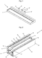
- FIG. 1 A housing 1 for accommodating components 2, 3, 4 of an alarm system and for accommodating in a rebate area of a window 6 or a door according to the invention is shown.
- the housing 1 comprises a base body 7 and at least one channel 8, 8 ', 8 ", the housing 1 in the in Fig. 1 Embodiment shown comprises three channels 8, 8 ', 8 ", which are integrally formed on the housing 1.
- the housing is preferably made of a polyamide, here polyamide-12.
- the base body 7 can be closed by a cover.
- Components 2, 3, 4 of an alarm system are accommodated in the housing 1.
- a motion detector 2 a camera 3 and a light source 4 designed as an LED arranged such that the detection of events and / or delivery of signals to the outside are arranged sealingly at the respective channel end.
- the motion detector 2, the camera 3 and the LED 4 are sealed and aligned in the housing 1, whereby the sensitive components 2, 3, 4 of the alarm system are protected from moisture.
- the motion detector 2, the camera 3 and the LED 4 conduct electricity and signals with a circuit board (not shown) which is located in the base body 7 of the housing 1.
- a shock sensor (not shown), a data transmission device (not shown), which serves to exchange data with the control element of the alarm system, and a power supply, also not shown, are also accommodated in the base body 7.
- Fig. 2 shows a perspective view of a section of a frame 9 of a window 6 according to the invention, in which the in Fig. 1 housing 1 shown is used.
- the frame is produced by welding miter-cut profile pieces of a frame profile 10.
- the frame profile 10 of the window 6 according to the invention is made of a thermoplastic polymer material, preferably polyvinyl chloride (PVC), in particular hard PVC (PVC-U) or glass fiber reinforced PVC, the additional additives such. B. stabilizers, plasticizers, pigments and the like are added, is extruded. It is constructed from a multiplicity of hollow chambers 11, 11 ", 11 '", which are each surrounded by webs of the frame profile 10.
- the frame profile 10 comprises a main hollow chamber 12 for inserting a reinforcing element.
- the window frame profile 10 comprises a weather-side profile outer wall 13 with an outer rollover 14 and a room-side profile outer wall 15 opposite the weather-side profile outer wall 13.
- the window frame profile 10 has a groove 16 in which striking plates can be anchored.
- a rebate area is defined by the outer rollover 14, an upper web 17 of the main hollow chamber 12 and the groove 16, in which the housing 1 is accommodated.
- openings are preferably made in the weather-side profile outer wall 13 of the window frame profile 10 using a suitable drilling jig which specifies the position of the channels 8, 8 ', 8 ", and the channels 8, 8 ', 8 "of the housing 1 through the openings formed guided.
- the outward-facing sensors or components 2, 3, 4 of the alarm system from which changes in the outside world that are relevant to the alarm can be detected, are positioned in the outer flap 14 facing the window reveal. In this way, the alarm system detects the relevant area immediately in front of the window 6.
- the base body 7 of the housing 1 is fastened to the frame profile 10 by a screw.
- the components 2, 3, 4 of the alarm system can be supplied with power via a line led through the main hollow chamber 12 or via a battery likewise accommodated in the base body 7.
- the assembly of the housing in the frame 9 and thus the installation of an alarm system in the window 6 according to the invention is simplified in such a way that the assembly can only be easily carried out on the construction site. It is also possible to retrofit an already installed window with an Alram system.
Landscapes
- Engineering & Computer Science (AREA)
- Civil Engineering (AREA)
- Structural Engineering (AREA)
- Physics & Mathematics (AREA)
- General Physics & Mathematics (AREA)
- Burglar Alarm Systems (AREA)
Description
- Die vorliegende Erfindung betrifft ein Fenster oder eine Tür, das einen aus Rahmenprofilen gebildeten Blendrahmen; einen aus Rahmenprofilen gebildeten Flügelrahmen; und ein Flächenelement, das in den Flügelrahmen aufgenommen ist und das stirnseitig von den Flügelrahmenprofilen umlaufen wird; wobei mindestens ein Rahmenprofil eine wetterseitige Profilaußenwand mit einem Außenüberschlag sowie einen daran angrenzenden Falzbereich umfasst, und wobei in dem Falzbereich mehrere Komponenten eines Alarmsystems angeordnet sind.
- Im Stand der Technik ist eine Vielzahl derartiger Fenster oder Türen beschrieben. Als Beispiel dafür seien die
DE 20 2006 014 916 U1 und dieUS2012/268274 genannt. - Nach dem Stand der Technik sind die Komponenten des Alarmsystems meist in den Fensterfalzbereich zwischen dem Flügel- und dem Blendrahmen montiert oder direkt auf die Innenseite des Fensters geklebt oder geschraubt. Ebenfalls bekannt ist es, Komponenten des Alarmsystems in den Fenstergriff zu integrieren. Die Komponenten des Alarmsystems beinhalten stets Sensoren, bei denen es sich häufig um Fensteröffnungskontakte (Reed-Relais), die mit einem Magneten geschaltet sind, Hall-Sensoren, Glasbruchsensoren und Erschütterungssensoren, die auf dem Glas und/oder im Fenstergriff positioniert sind, handelt. Bei einer derartigen Anordnung der Sensoren im Fenster oder auf der Innenseite des Fensters wird der Einbruch aber erst erkannt, wenn der Flügel des Fensters aufgebrochen wird. Durch zur Außenseite des Fensters oder der Tür gerichtete Sensoren, wie beispielsweise einen Bewegungsmelder, kann es häufig zu Fehlarmen kommen, weshalb diese in Alarmsystemen bislang kaum eingesetzt werden. Darüber hinaus erfordern solche nach außen gerichtete Sensoren, die in eines der Rahmenprofile aufgenommen sind, eine aufwendige Bearbeitung der Fensterprofile, die nur von speziellen Fräsmaschinen und deshalb nicht Vorort auf der Baustelle durchgeführt werden können.
- An dieser Stelle setzt die vorliegende Erfindung ein, der die Aufgabe zugrunde liegt, ein Fenster oder eine Tür zur Verfügung zu stellen, das bzw. die die Nachteile des Stands der Technik überwindet. Insbesondere soll das erfindungsgemäße Fenster bzw. die erfindungsgemäße Tür eine einfache und auf der Baustelle durchführbare Integration von Komponenten eines Alarmsystems das erfindungsgemäße Fenster bzw. die erfindungsgemäße Tür ermöglichen. Darüber hinaus soll es das erfindungsgemäße Fenster bzw. die erfindungsgemäße Tür ermöglichen, die Gefahr von Fehlalarmen zu reduzieren.
- Diese und andere Aufgaben werden durch ein Fenster bzw. eine Tür mit den Merkmalen des Anspruches 1 gelöst. Vorteilhafte Ausführungsformen der vorliegenden Erfindung sind in den abhängigen Ansprüchen beschrieben.
- Gemäß der vorliegenden Erfindung wurde erkannt, dass durch ein Gehäuse, in das die in den Falzbereich zu integrierenden Komponenten eines Alarmsystems aufgenommen sind, die Installation eines Alarmsystems in ein Fenster bzw. in eine Tür derart vereinfacht wird, dass eine Montage ohne weiteres erst auf der Baustelle vorgenommen werden kann. Ebenso ist ein Nachrüsten eines bereits eingebauten Fensters oder einer bereits eingebauten Tür möglich. Das Gehäuse umfasst einen Grundkörper und mindestens einem Kanal, vorzugsweise mindestens zwei und insbesondere mindestens drei Kanäle. Im Einbauzustand in dem erfindungsgemäßen Fenster bzw. in der erfindungsgemäßen Tür ist der Kanal bzw. sind die Kanäle durch Öffnungen in der Außenwand eines der Rahmenprofile geführt. An den Kanalenden können sich die nach außen gerichteten Sensoren bzw. Bauteile des Alarmsystems befinden, von denen alarmrelevante Änderungen der Außenwelt detektiert werden können. In dem Kanal bzw. den Kanälen ist die elektrische Verbindung zu einer Platine des Alarmsystems geführt, die in dem Grundkörper des Gehäuses aufgenommen ist. Die Sensoren werden bei der Montage durch die Kanäle sicher nach außen geführt. Durch das Gehäuse werden die Sensoren und weitere empfindliche Komponenten des Alarmsystems vor Feuchtigkeit und sonstigen Witterungseinflüssen sowie vor mechanischen Einflüssen geschützt. Zur Integration des Gehäuses in das Fenster bzw. die Tür werden vorzugsweise mit einer geeigneten Bohrlehre, die die Position der Kanäle vorgibt, Öffnungen in die Außenwand eines der Rahmenprofile eingebracht, und die Kanäle des Gehäuses durch die entstanden Öffnungen geführt. Abschließend kann der Grundkörper des Gehäuses durch eine Schraube am Rahmenprofil befestigt werden.
- Dementsprechend stellt die vorliegende Erfindung ein Fenster bzw. eine Tür zur Verfügung, die einen aus Rahmenprofilen gebildeten Blendrahmen; einen aus Rahmenprofilen gebildeten Flügelrahmen; und ein Flächenelement, das in den Flügelrahmen aufgenommen ist und das stirnseitig von den Flügelrahmenprofilen umlaufen wird, umfasst; wobei mindestens ein Rahmenprofil eine wetterseitige Profilaußenwand mit einem Außenüberschlag sowie einen daran angrenzenden Falzbereich umfasst, und wobei in dem Falzbereich mehrere Komponenten eines Alarmsystems angeordnet sind; erfindungsgemäß ist das Fenster bzw. die Tür dadurch gekennzeichnet, dass die in den Falzbereich angeordneten Komponenten des Alarmsystems in ein Gehäuse aufgenommen sind, wobei das Gehäuse einen Grundkörper und mindestens einen Kanal umfasst, der durch mindestens eine Öffnung in der wetterseitigen Profilaußenwand des Rahmenprofils geführt ist.
- Wie hierin verwendet bezieht sich der Begriff "Fenster oder Tür" bevorzugt auf ein Kunststofffenster oder eine Kunststofftür. Es kommen aber auch Metallfenster oder Metalltüren, Holzfenster oder Holztüren sowie Verbundfenster und Verbundtüren in Betracht. Handelt es sich um ein Kunststofffenster oder eine Kunststofftür, so ist als Hauptmaterial der Rahmenprofile des erfindungsgemäßen Fensters oder der erfindungsgemäßen Tür Polyvinylchlorid (PVC), insbesondere Hart-PVC (PVC-U) oder glasfaserverstärktes PVC, dem zusätzlich jeweils Zusatzstoffe wie z. B. Stabilisatoren, Weichmacher, Pigmente und dergleichen zugesetzt sind, bevorzugt. PVC kann gut eingefärbt bzw. gefärbt werden und nimmt kaum Wasser auf. Derartige Rahmenprofile werden in an sich bekannter Weise mittels Extrusion bzw. Coextrusion hergestellt. Faserverstärkte Kunststoffprofile ermöglichen es, die sonst in die Haupthohlkammer der Rahmenprofile einzuführende Armierung beispielsweise aus Stahl wegzulassen. Hinsichtlich Details zum Aufbau und zur Herstellung eines derartigen zumindest teilweise faserverstärktem Kunststoffprofils wird auf die
WO 2009/024264 A1 verwiesen. Aus den extrudierten bzw. coextrudierten Rahmenprofilen können Türen bzw. Fenster hergestellt werden, indem die Rahmenprofile auf Gehrung geschnitten werden und die auf Gehrung geschnittenen Kunststoffprofilstücke in den Eckbereichen unter Bildung der Rahmenbaugruppen entsprechender Fenster bzw. Türen verschweißt werden. - Es kann sich auch als günstig erweisen, wenn es sich bei dem Gehäuse um ein metallisches Bauteil oder ein Kunststoff-Bauteil handelt. Derartige metallische Gehäuse oder Kunststoff- Gehäuse begünstigen dessen Stabilität. Darüber hinaus können sie kostengünstig hergestellt werden. Dabei haben sich insbesondere Aluminium, Edelstahl, eine Aluminium-Druckgusslegierung, eine Zink-Druckgusslegierung sowie eine Aluminium-Zink-Druckgusslegierung, Acrylnitril-Styrol-Acrylester (ASA), Polyamid (PA), Polyoxymethylen (POM) oder faserverstärkte Polymere, insbesondere glasfaserverstärkte Polymere als besonders geeignete Materialien erwiesen.
- Hinsichtlich des erfindungsgemäßen Fenster bzw. der erfindungsgemäßen Tür kann es von Vorteil sein, wenn mindestens ein Kanal jeweils durch eine Öffnung im Außenüberschlag des Rahmenprofils geführt ist. Bevorzugt ist mehr als ein Kanal durch jeweils durch eine Öffnung im Außenüberschlag des Rahmenprofils geführt. Dadurch ist gewährleistet, dass die nach außen gerichteten Sensoren bzw. Komponenten des Alarmsystems, von denen alarmrelevante Änderungen der Außenwelt detektiert werden können, im Außenüberschlag zur Fensterlaibung positioniert sind. Dadurch ist es möglich, dass das Alarmsystem den relevanten Bereich unmittelbar vor dem Fenster bzw. der Tür erfasst. Weiterhin können die relevanten Komponenten nicht durch Vorbauten, wie beispielweise Rollladenschienen, verdeckt werden.
- Zusätzlich oder alternativ dazu kann es hilfreich sein, wenn mindestens ein Kanal wenigstens in einem Abschnitt, in dem der Kanal die wetterseitige Profilaußenwand des Rahmenprofils durchdringt, zumindest annähernd parallel zu einer Ebene des Flächenelements verläuft. Dadurch wird das Detektieren des Alarmsystems weitestgehend auf den relevanten Bereich unmittelbar vor dem Fenster bzw. der Tür beschränkt.
- Es ist auch bevorzugt, wenn die Komponenten des Alarmsystems feuchtigkeitsdicht in dem Gehäuse aufgenommen sind. Insbesondere die Sensoren sollen eingedichtet und ausgerichtet in das Gehäuse aufgenommen sein. So sind die empfindlichen Komponenten vor Feuchtigkeitseinflüssen weitestgehend geschützt.
- Ebenso kann es von Nutzen sein, wenn die Komponenten des Alarmsystems eine Kamera, einen Sensor, eine Lichtquelle, einen akustischen Signalgeber, eine Datenübertragungsvorrichtung, eine Stromversorgung, eine Platine (und/oder Kombinationen der Genannten beinhalten.
- Es kann auch vorteilhaft sein, wenn das Alarmsystem die Kamera, die Lichtquelle und/oder den Sensor umfasst, wobei die Kamera, die Lichtquelle und/oder der Sensor zumindest teilweise in den Kanälen angeordnet sind. Somit ist gewährleistet, dass sich die Sensoren bzw. Bauteile des Alarmsystems, von denen alarmrelevante Änderungen der Außenwelt detektiert werden können, in der Nähe des Flächenelements befinden und dort diese Änderungen detektieren und/oder registrieren und/oder eine Reaktion auf eine solche Änderungen ausführen können.
- Es kann auch bevorzugt sein, wenn die Komponenten des Alarmsystems und einen Beschleunigungs- oder Erschütterungssensor und ein weiteres Sensorelement, insbesondere eine Kamera und/oder einen Bewegungsmelder, Kamera umfassen, wobei ein Alarmsignal durch das Alarmsystem ausgelöst wird, wenn sowohl der Beschleunigungs- oder Erschütterungssensor als auch das weitere Sensorelement eine Zustandsänderung ermitteln. Dadurch können Fehlalarme vermieden, der Stromverbrauch reduziert und somit die Batterielaufzeit verlängert werden.
- Das erfindungsgemäße Fenster und/oder die erfindungsgemäße Tür sowie einzelne Teile davon können auch zeilenweise oder schichtweise unter Verwendung eines zeilenaufbauenden oder schichtaufbauenden Fertigungsverfahrens (z. B. 3D-Druck) hergestellt werden.
- Im Folgenden soll die Erfindung anhand der in den Figuren dargestellten, nicht einschränkenden Ausführungsbeispielen nicht näher beschrieben werden.
- Es zeigen:
- Fig. 1
- eine perspektivische Darstellung eines Gehäuses zur Verwendung in einem Fenster gemäß einer Ausführungsform der vorliegenden Erfindung; und
- Fig. 2
- eine perspektivische Darstellung eines Ausschnitts eines Rahmens eines erfindungsgemäßen Fensters, in dem das in
Fig. 1 dargestellte Gehäuse eingesetzt ist. - In
Fig. 1 ist ein Gehäuse 1 zur Aufnahme von Komponenten 2, 3, 4 eines Alarmsystems und zur Aufnahme in einen Falzbereich eines erfindungsgemäßen Fensters 6 oder einer erfindungsgemäßen Tür gezeigt. Das Gehäuse 1 umfasst einen Grundkörper 7 und mindestens einen Kanal 8, 8', 8", wobei das Gehäuse 1 in der inFig. 1 dargestellten Ausführungsform drei Kanäle 8, 8', 8" umfasst, die einstückig an das Gehäuse 1 angeformt sind. Das Gehäuse ist vorzugsweise aus einem Polyamid, hier Polyamid-12, hergestellt. Der Grundkörper 7 kann durch einen Deckel verschlossen werden. - In das Gehäuse 1 sind Komponenten 2, 3, 4 eines Alarmsystems aufgenommen. Dabei sind in der in
Fig. 1 dargestellten Ausführungsform in den Kanälen 8, 8', 8" ein Bewegungsmelder 2, eine Kamera 3 und eine als LED ausgebildete Lichtquelle 4 derart angeordnet, dass die zur Detektion von Ereignissen und/oder Abgabe von Signalen an das Äußere dichtend am jeweiligen Kanalende angeordnet sind. Der Bewegungsmelder 2, die Kamera 3 und die LED 4 sind dichtend und ausgerichtet in das Gehäuse 1 aufgenommen, wodurch die empfindlichen Komponenten 2, 3, 4 des Alarmsystems vor Feuchtigkeitseinflüssen geschützt sind. Der Bewegungsmelder 2, die Kamera 3 und die LED 4 sind strom- und signalleitend mit einer Platine (nicht dargestellt), die sich im Grundkörper 7 des Gehäuses 1 befindet. Darüber hinaus sind in den Grundkörper 7 auch ein Erschütterungssensor (nicht dargestellt), eine Datenübertragungsvorrichtung (nicht dargestellt), die zum Austausch von Daten mit dem Steuerelement der Alarmanlage dient, sowie eine ebenfalls nicht dargestellte Stromversorgung aufgenommen. -
Fig. 2 zeigt eine perspektivische Darstellung eines Ausschnitts eines Blendrahmens 9 eines erfindungsgemäßen Fensters 6, in dem das inFig. 1 dargestellte Gehäuse 1 eingesetzt ist. Der Blendrahmen ist durch Verschweißen von auf Gehrung geschnittenen Profilstücken eines Blendrahmenprofils 10 hergestellt. Das Blendrahmenprofil 10 des erfindungsgemäßen Fensters 6 ist aus einem thermoplastischen Polymermaterial, vorzugsweise Polyvinylchlorid (PVC), insbesondere Hart-PVC (PVC-U) oder glasfaserverstärktem PVC, dem zusätzlich Zusatzstoffe wie z. B. Stabilisatoren, Weichmacher, Pigmente und dergleichen zugesetzt sind, extrudiert ist. Es ist aus einer Vielzahl von Hohlkammern 11, 11", 11'" aufgebaut, die jeweils von Stegen des Blendrahmenprofils 10 umgeben sind. Zentral umfasst das Blendrahmenprofil 10 eine Haupthohlkammer 12 zum Einsetzen eines Armierungselements. Das Blendrahmenprofil 10 umfasst eine wetterseitige Profilaußenwand 13 mit einem Außenüberschlag 14 und eine der wetterseitigen Profilaußenwand 13 gegenüberliegende raumseitige Profilaußenwand 15. Im Bereich der raumseitigen Profilaußenwand 15 weist das Blendrahmenprofil 10 eine Nut 16 auf, in der Schließbleche verankert werden können. Durch den Außenüberschlag 14, einen oberen Steg 17 der Haupthohlkammer 12 und der Nut 16 ist ein Falzbereich definiert, in den das Gehäuse 1 aufgenommen ist. Am Außenüberschlag 14 befindet sich eine weitere Nut 18 zur Aufnahme einer nicht dargestellten Anschlagsdichtung, an der ein an den Blendrahmen 9 drehend angelegter Flügelrahmen mit einem Flächenelement, insbesondere einer Isolierverglasung, anschlägt. - Zur Montage des Gehäuses 1 in den Blendrahmen 9 des erfindungsgemäßen Fensters 6 werden vorzugsweise mit einer geeigneten Bohrlehre, die die Position der Kanäle 8, 8', 8" vorgibt, Öffnungen in die wetterseitige Profilaußenwand 13 des Blendrahmenprofils 10 eingebracht, und die Kanäle 8, 8', 8" des Gehäuses 1 durch die entstandenen Öffnungen geführt. Dadurch sind die nach außen gerichteten Sensoren bzw. Komponenten 2, 3, 4 des Alarmsystems, von denen alarmrelevante Änderungen der Außenwelt detektiert werden können, im Außenüberschlag 14 zur Fensterlaibung gerichtet positioniert. Auf diese Weise erfasst das Alarmsystem den relevanten Bereich unmittelbar vor dem Fenster 6. Abschließend wird der Grundkörper 7 des Gehäuses 1 durch eine Schraube am Blendrahmenprofil 10 befestigt. Die Stromversorgung der Komponenten 2, 3, 4 des Alarmsystems kann über eine durch die Haupthohlkammer 12 geführte Leitung oder über eine ebenfalls in den Grundkörper 7 aufgenommene Batterie erfolgen. Die Montage des Gehäuses in den Blendrahmen 9 und damit die Installation eines Alarmsystems in das erfindungsgemäße Fenster 6 ist so vereinfacht, dass die Montage problemlos erst auf der Baustelle erfolgen kann. Ebenso ist ein Nachrüsten eines bereits eingebauten Fensters mit einem Alramsystem möglich.
- In dem Bereich, in denen die Kanäle 8, 8', 8" durch die wetterseitige Profilaußenwand 13 des Blendrahmenprofils 10 treten, sind diese im Wesentlichen parallel zur Ebene des Flächenelements ausgerichtet. Dadurch ist das Detektieren durch das Alarmsystem weitestgehend auf den relevanten Bereich unmittelbar vor dem Fenster 6 beschränkt, wodurch Fehlalarme vermieden werden können.
- Die Erfindung wurde vorangehend exemplarisch unter Bezugnahme auf die in den Figuren dargestellten Ausführungsformen der vorliegenden Erfindung im Detail erläutert. Es versteht sich jedoch, dass der Fachmann auf dieser Offenbarung weitere Ausführungen der vorliegenden Erfindung erkennt, ohne den Schutzbereich der beigefügten Ansprüche zu verlassen.
Claims (7)
- Fenster (6) oder Tür, umfassend- einen aus Rahmenprofilen (10) gebildeten Blendrahmen (9);- einen aus Rahmenprofilen gebildeten Flügelrahmen; und- ein Flächenelement, das in den Flügelrahmen aufgenommen ist und das stirnseitig von den Flügelrahmenprofilen umlaufen wird; wobeidadurch gekennzeichnet, dass
mindestens ein Rahmenprofil (10) eine wetterseitige Profilaußenwand (13) mit einem Außenüberschlag (14) sowie einen daran angrenzenden Falzbereich umfasst, und wobei
in dem Falzbereich mehrere Komponenten (2, 3; 4) eines Alarmsystems angeordnet sind,
die in dem Falzbereich angeordneten Komponenten (2, 3; 4) des Alarmsystems in ein Gehäuse (1) aufgenommen sind, wobei das Gehäuse (1) einen Grundkörper (7) und mindestens einen Kanal (8, 8'; 8") umfasst, der durch mindestens eine Öffnung in der wetterseitigen Profilaußenwand (13) des Rahmenprofils (10) geführt ist. - Fenster (6) oder Tür nach Anspruch 1, dadurch gekennzeichnet, dass mindestens ein Kanal (8, 8', 8") durch eine Öffnung im Außenüberschlag (14) des Rahmenprofils (10) geführt ist.
- Fenster (6) oder Tür nach Anspruch 1 oder Anspruch 2, dadurch gekennzeichnet, dass mindestens ein Kanal (8, 8'; 8") wenigstens in einem Abschnitt, in dem der Kanal (8, 8'; 8") die wetterseitige Profilaußenwand (13) des Rahmenprofils (10) durchdringt, zumindest annähernd parallel zu einer Ebene des Flächenelements verläuft.
- Fenster (6) oder Tür nach einem der Ansprüche 1 bis 3, dadurch gekennzeichnet, dass die Komponenten (2, 3, 4) des Alarmsystems feuchtigkeitsdicht in dem Gehäuse (1) aufgenommen sind.
- Fenster (6) oder Tür nach einem der Ansprüche 1 bis 4, dadurch gekennzeichnet, dass die Komponenten (2, 3, 4) des Alarmsystems eine Kamera (3), einen Sensor (2), eine Lichtquelle (4), einen akustischen Signalgeber, eine Datenübertragungsvorrichtung, eine Stromversorgung, eine Platine und/oder Kombinationen der Genannten beinhalten.
- Fenster (6) oder Tür nach einem der Ansprüche 1 bis 5, dadurch gekennzeichnet, dass das Alarmsystem die Kamera (3), die Lichtquelle (4) und/oder den Sensor (3) umfasst, wobei die Kamera (3), die Lichtquelle (4) und/oder der Sensor (2) zumindest teilweise in den Kanälen (8, 8', 8") angeordnet sind.
- Fenster (1) oder Tür nach einem der Ansprüche 1 bis 6, dadurch gekennzeichnet, dass die Komponenten (2, 3, 4) des Alarmsystems einen Beschleunigungs- oder Erschütterungssensor und ein weiteres Sensorelement, insbesondere eine Kamera (3) und/oder einen Bewegungsmelder, umfassen, wobei ein Alarmsignal durch das Alarmsystem ausgelöst wird, wenn sowohl der Beschleunigungs- oder Erschütterungssensor als auch das weitere Sensorelement eine Zustandsänderung ermitteln.
Applications Claiming Priority (1)
| Application Number | Priority Date | Filing Date | Title |
|---|---|---|---|
| DE202017101993.4U DE202017101993U1 (de) | 2017-04-04 | 2017-04-04 | Fenster oder Tür |
Publications (2)
| Publication Number | Publication Date |
|---|---|
| EP3385927A1 EP3385927A1 (de) | 2018-10-10 |
| EP3385927B1 true EP3385927B1 (de) | 2020-01-22 |
Family
ID=61750014
Family Applications (1)
| Application Number | Title | Priority Date | Filing Date |
|---|---|---|---|
| EP18163280.3A Active EP3385927B1 (de) | 2017-04-04 | 2018-03-22 | Fenster oder tür mit angeordneten komponenten eines alarmsystems |
Country Status (2)
| Country | Link |
|---|---|
| EP (1) | EP3385927B1 (de) |
| DE (1) | DE202017101993U1 (de) |
Family Cites Families (10)
| Publication number | Priority date | Publication date | Assignee | Title |
|---|---|---|---|---|
| IT1079149B (it) * | 1976-10-19 | 1985-05-08 | Arrigoni Carlo | Porta di sicurezza per edifici |
| GB9301709D0 (en) * | 1993-01-28 | 1993-03-17 | Highfalls Holdings Inc | Detector for wing sash or frame |
| GB9925240D0 (en) * | 1999-10-26 | 1999-12-29 | Briggs Leslie G | Sensor for security system |
| US6720874B2 (en) * | 2000-09-29 | 2004-04-13 | Ids Systems, Inc. | Portal intrusion detection apparatus and method |
| DE202006014916U1 (de) * | 2006-09-25 | 2007-01-18 | Herold, Frank | Elektrische Alarmanlage für Türen und/oder Fenster |
| DE102007032504B4 (de) * | 2007-07-12 | 2026-05-13 | Link Gmbh | Sensoreinrichtung zur berührungsfreien Identitäts- oder Positionsermittlung |
| US8269627B2 (en) * | 2007-11-30 | 2012-09-18 | Andersen Corporation | Status monitoring system for a fenestration unit |
| AT508766B1 (de) * | 2010-01-18 | 2011-04-15 | Stefan Dipl Ing Wieser | Vorrichtung und verfahren zum überwachen einer gebäudeöffnung |
| WO2011085420A1 (de) * | 2010-01-18 | 2011-07-21 | Stefan Wieser | Vorrichtung und verfahren zum überwachen einer gebäudeöffnung |
| US9262901B1 (en) * | 2012-04-25 | 2016-02-16 | Todd Mona | Identification system and method of use |
-
2017
- 2017-04-04 DE DE202017101993.4U patent/DE202017101993U1/de not_active Expired - Lifetime
-
2018
- 2018-03-22 EP EP18163280.3A patent/EP3385927B1/de active Active
Non-Patent Citations (1)
| Title |
|---|
| None * |
Also Published As
| Publication number | Publication date |
|---|---|
| DE202017101993U1 (de) | 2018-07-05 |
| EP3385927A1 (de) | 2018-10-10 |
Similar Documents
| Publication | Publication Date | Title |
|---|---|---|
| EP3516147B1 (de) | Beschusshemmendes rolltor | |
| EP3221540B1 (de) | Dichtungsvorrichtung für einen verschiebbaren flügel als schiebeflügel oder verschiebbaren hebe-schiebeflügel eines fensters oder einer tür | |
| DE202019107047U1 (de) | Fenster- oder Türflügel sowie diesen umfassendes Fenster oder diesen umfassende Tür | |
| EP3660256B1 (de) | Flügel für ein fenster oder eine tür, diesen umfassendes fenster sowie diesen umfassende tür | |
| EP1582685B1 (de) | Putzanschlussleiste für Fensterrahmen oder dgl. mit Basisteil und Anputzteil | |
| EP3660255B1 (de) | Flügel für ein fenster oder eine tür, diesen umfassendes fenster sowie diesen umfassende tür | |
| DE202018106828U1 (de) | Flügel für ein Fenster oder eine Tür, diesen umfassendes Fenster sowie diesen umfassende Tür | |
| EP3385927A1 (de) | Fenster oder tür mit angeordneten komponenten eines alarmsystems | |
| EP3673136B1 (de) | Dichtungsvorrichtung für einen verschiebbaren flügel als schiebeflügel oder verschiebbaren hebe-schiebeflügel eines fensters oder einer tür | |
| EP1070820A2 (de) | Fenster | |
| EP1384847A2 (de) | Hochwasserschutzsystem | |
| DE102014218072A1 (de) | Hochwasserschutzfenster oder Hochwasserschutztür | |
| EP1854956A1 (de) | Vorrichtung zum temporären Abdichten einer Öffnung | |
| EP1353035A2 (de) | Fenster oder Tür | |
| AT523463A1 (de) | Verschlusselement für eine Gebäudeöffnung | |
| EP4202168B1 (de) | Fenster- oder türflügel sowie diesen umfassende(s) fenster oder tür | |
| DE202024107522U1 (de) | Türflügel sowie diesen umfassende Tür | |
| EP2412884B1 (de) | Aufsatzkonstruktion für Fassadenelemente in Pfosten-Riegel-Bauweise mit verbesserter Wärmeisoliereigenschaft | |
| DE202024107512U1 (de) | Türflügel sowie diesen umfassende Tür | |
| EP4202169B1 (de) | Fenster- oder türflügel sowie diesen umfassende(s) fenster oder tür | |
| DE102017208479A1 (de) | Abdeckungsanordnung für Fenster | |
| DE202018106824U1 (de) | Flügel für ein Fenster oder eine Tür, diesen umfassendes Fenster sowie diesen umfassende Tür | |
| EP3828372B1 (de) | Fenster- oder türflügel sowie diesen umfassende(s) fenster oder tür | |
| DE29706174U1 (de) | Langsensor für Dichtungsprofile einsetzbar in Zargenfugen als Signalauslöser | |
| EP4137660A1 (de) | Gebäudeverschlusselement, verfahren zum herstellen und montieren eines gebäudeverschlusselements sowie montagesatz zum herstellen von mehreren gebäudeverschlusselementen |
Legal Events
| Date | Code | Title | Description |
|---|---|---|---|
| PUAI | Public reference made under article 153(3) epc to a published international application that has entered the european phase |
Free format text: ORIGINAL CODE: 0009012 |
|
| STAA | Information on the status of an ep patent application or granted ep patent |
Free format text: STATUS: THE APPLICATION HAS BEEN PUBLISHED |
|
| AK | Designated contracting states |
Kind code of ref document: A1 Designated state(s): AL AT BE BG CH CY CZ DE DK EE ES FI FR GB GR HR HU IE IS IT LI LT LU LV MC MK MT NL NO PL PT RO RS SE SI SK SM TR |
|
| AX | Request for extension of the european patent |
Extension state: BA ME |
|
| STAA | Information on the status of an ep patent application or granted ep patent |
Free format text: STATUS: REQUEST FOR EXAMINATION WAS MADE |
|
| 17P | Request for examination filed |
Effective date: 20190409 |
|
| RBV | Designated contracting states (corrected) |
Designated state(s): AL AT BE BG CH CY CZ DE DK EE ES FI FR GB GR HR HU IE IS IT LI LT LU LV MC MK MT NL NO PL PT RO RS SE SI SK SM TR |
|
| GRAP | Despatch of communication of intention to grant a patent |
Free format text: ORIGINAL CODE: EPIDOSNIGR1 |
|
| STAA | Information on the status of an ep patent application or granted ep patent |
Free format text: STATUS: GRANT OF PATENT IS INTENDED |
|
| INTG | Intention to grant announced |
Effective date: 20190822 |
|
| GRAS | Grant fee paid |
Free format text: ORIGINAL CODE: EPIDOSNIGR3 |
|
| GRAA | (expected) grant |
Free format text: ORIGINAL CODE: 0009210 |
|
| STAA | Information on the status of an ep patent application or granted ep patent |
Free format text: STATUS: THE PATENT HAS BEEN GRANTED |
|
| AK | Designated contracting states |
Kind code of ref document: B1 Designated state(s): AL AT BE BG CH CY CZ DE DK EE ES FI FR GB GR HR HU IE IS IT LI LT LU LV MC MK MT NL NO PL PT RO RS SE SI SK SM TR |
|
| REG | Reference to a national code |
Ref country code: GB Ref legal event code: FG4D Free format text: NOT ENGLISH |
|
| REG | Reference to a national code |
Ref country code: CH Ref legal event code: EP |
|
| REG | Reference to a national code |
Ref country code: AT Ref legal event code: REF Ref document number: 1227411 Country of ref document: AT Kind code of ref document: T Effective date: 20200215 |
|
| REG | Reference to a national code |
Ref country code: IE Ref legal event code: FG4D Free format text: LANGUAGE OF EP DOCUMENT: GERMAN |
|
| REG | Reference to a national code |
Ref country code: DE Ref legal event code: R096 Ref document number: 502018000641 Country of ref document: DE |
|
| REG | Reference to a national code |
Ref country code: NL Ref legal event code: MP Effective date: 20200122 |
|
| REG | Reference to a national code |
Ref country code: LT Ref legal event code: MG4D |
|
| PG25 | Lapsed in a contracting state [announced via postgrant information from national office to epo] |
Ref country code: RS Free format text: LAPSE BECAUSE OF FAILURE TO SUBMIT A TRANSLATION OF THE DESCRIPTION OR TO PAY THE FEE WITHIN THE PRESCRIBED TIME-LIMIT Effective date: 20200122 Ref country code: FI Free format text: LAPSE BECAUSE OF FAILURE TO SUBMIT A TRANSLATION OF THE DESCRIPTION OR TO PAY THE FEE WITHIN THE PRESCRIBED TIME-LIMIT Effective date: 20200122 Ref country code: NO Free format text: LAPSE BECAUSE OF FAILURE TO SUBMIT A TRANSLATION OF THE DESCRIPTION OR TO PAY THE FEE WITHIN THE PRESCRIBED TIME-LIMIT Effective date: 20200422 Ref country code: PT Free format text: LAPSE BECAUSE OF FAILURE TO SUBMIT A TRANSLATION OF THE DESCRIPTION OR TO PAY THE FEE WITHIN THE PRESCRIBED TIME-LIMIT Effective date: 20200614 Ref country code: NL Free format text: LAPSE BECAUSE OF FAILURE TO SUBMIT A TRANSLATION OF THE DESCRIPTION OR TO PAY THE FEE WITHIN THE PRESCRIBED TIME-LIMIT Effective date: 20200122 |
|
| PGFP | Annual fee paid to national office [announced via postgrant information from national office to epo] |
Ref country code: IE Payment date: 20200409 Year of fee payment: 3 |
|
| PG25 | Lapsed in a contracting state [announced via postgrant information from national office to epo] |
Ref country code: IS Free format text: LAPSE BECAUSE OF FAILURE TO SUBMIT A TRANSLATION OF THE DESCRIPTION OR TO PAY THE FEE WITHIN THE PRESCRIBED TIME-LIMIT Effective date: 20200522 Ref country code: SE Free format text: LAPSE BECAUSE OF FAILURE TO SUBMIT A TRANSLATION OF THE DESCRIPTION OR TO PAY THE FEE WITHIN THE PRESCRIBED TIME-LIMIT Effective date: 20200122 Ref country code: LV Free format text: LAPSE BECAUSE OF FAILURE TO SUBMIT A TRANSLATION OF THE DESCRIPTION OR TO PAY THE FEE WITHIN THE PRESCRIBED TIME-LIMIT Effective date: 20200122 Ref country code: GR Free format text: LAPSE BECAUSE OF FAILURE TO SUBMIT A TRANSLATION OF THE DESCRIPTION OR TO PAY THE FEE WITHIN THE PRESCRIBED TIME-LIMIT Effective date: 20200423 Ref country code: BG Free format text: LAPSE BECAUSE OF FAILURE TO SUBMIT A TRANSLATION OF THE DESCRIPTION OR TO PAY THE FEE WITHIN THE PRESCRIBED TIME-LIMIT Effective date: 20200422 Ref country code: HR Free format text: LAPSE BECAUSE OF FAILURE TO SUBMIT A TRANSLATION OF THE DESCRIPTION OR TO PAY THE FEE WITHIN THE PRESCRIBED TIME-LIMIT Effective date: 20200122 |
|
| REG | Reference to a national code |
Ref country code: DE Ref legal event code: R097 Ref document number: 502018000641 Country of ref document: DE |
|
| PG25 | Lapsed in a contracting state [announced via postgrant information from national office to epo] |
Ref country code: SM Free format text: LAPSE BECAUSE OF FAILURE TO SUBMIT A TRANSLATION OF THE DESCRIPTION OR TO PAY THE FEE WITHIN THE PRESCRIBED TIME-LIMIT Effective date: 20200122 Ref country code: LT Free format text: LAPSE BECAUSE OF FAILURE TO SUBMIT A TRANSLATION OF THE DESCRIPTION OR TO PAY THE FEE WITHIN THE PRESCRIBED TIME-LIMIT Effective date: 20200122 Ref country code: SK Free format text: LAPSE BECAUSE OF FAILURE TO SUBMIT A TRANSLATION OF THE DESCRIPTION OR TO PAY THE FEE WITHIN THE PRESCRIBED TIME-LIMIT Effective date: 20200122 Ref country code: MC Free format text: LAPSE BECAUSE OF FAILURE TO SUBMIT A TRANSLATION OF THE DESCRIPTION OR TO PAY THE FEE WITHIN THE PRESCRIBED TIME-LIMIT Effective date: 20200122 Ref country code: ES Free format text: LAPSE BECAUSE OF FAILURE TO SUBMIT A TRANSLATION OF THE DESCRIPTION OR TO PAY THE FEE WITHIN THE PRESCRIBED TIME-LIMIT Effective date: 20200122 Ref country code: DK Free format text: LAPSE BECAUSE OF FAILURE TO SUBMIT A TRANSLATION OF THE DESCRIPTION OR TO PAY THE FEE WITHIN THE PRESCRIBED TIME-LIMIT Effective date: 20200122 Ref country code: CZ Free format text: LAPSE BECAUSE OF FAILURE TO SUBMIT A TRANSLATION OF THE DESCRIPTION OR TO PAY THE FEE WITHIN THE PRESCRIBED TIME-LIMIT Effective date: 20200122 Ref country code: RO Free format text: LAPSE BECAUSE OF FAILURE TO SUBMIT A TRANSLATION OF THE DESCRIPTION OR TO PAY THE FEE WITHIN THE PRESCRIBED TIME-LIMIT Effective date: 20200122 Ref country code: EE Free format text: LAPSE BECAUSE OF FAILURE TO SUBMIT A TRANSLATION OF THE DESCRIPTION OR TO PAY THE FEE WITHIN THE PRESCRIBED TIME-LIMIT Effective date: 20200122 |
|
| RAP2 | Party data changed (patent owner data changed or rights of a patent transferred) |
Owner name: REHAU AG + CO |
|
| PLBE | No opposition filed within time limit |
Free format text: ORIGINAL CODE: 0009261 |
|
| STAA | Information on the status of an ep patent application or granted ep patent |
Free format text: STATUS: NO OPPOSITION FILED WITHIN TIME LIMIT |
|
| 26N | No opposition filed |
Effective date: 20201023 |
|
| PG25 | Lapsed in a contracting state [announced via postgrant information from national office to epo] |
Ref country code: IT Free format text: LAPSE BECAUSE OF FAILURE TO SUBMIT A TRANSLATION OF THE DESCRIPTION OR TO PAY THE FEE WITHIN THE PRESCRIBED TIME-LIMIT Effective date: 20200122 |
|
| PG25 | Lapsed in a contracting state [announced via postgrant information from national office to epo] |
Ref country code: SI Free format text: LAPSE BECAUSE OF FAILURE TO SUBMIT A TRANSLATION OF THE DESCRIPTION OR TO PAY THE FEE WITHIN THE PRESCRIBED TIME-LIMIT Effective date: 20200122 Ref country code: PL Free format text: LAPSE BECAUSE OF FAILURE TO SUBMIT A TRANSLATION OF THE DESCRIPTION OR TO PAY THE FEE WITHIN THE PRESCRIBED TIME-LIMIT Effective date: 20200122 |
|
| PG25 | Lapsed in a contracting state [announced via postgrant information from national office to epo] |
Ref country code: IE Free format text: LAPSE BECAUSE OF NON-PAYMENT OF DUE FEES Effective date: 20210322 |
|
| REG | Reference to a national code |
Ref country code: DE Ref legal event code: R081 Ref document number: 502018000641 Country of ref document: DE Owner name: REHAU INDUSTRIES SE & CO. KG, DE Free format text: FORMER OWNER: REHAU AG + CO, 95111 REHAU, DE |
|
| REG | Reference to a national code |
Ref country code: LU Ref legal event code: PD Owner name: REHAU INDUSTRIES SE & CO. KG; DE Free format text: FORMER OWNER: REHAU AG + CO Effective date: 20220329 |
|
| PG25 | Lapsed in a contracting state [announced via postgrant information from national office to epo] |
Ref country code: TR Free format text: LAPSE BECAUSE OF FAILURE TO SUBMIT A TRANSLATION OF THE DESCRIPTION OR TO PAY THE FEE WITHIN THE PRESCRIBED TIME-LIMIT Effective date: 20200122 Ref country code: MT Free format text: LAPSE BECAUSE OF FAILURE TO SUBMIT A TRANSLATION OF THE DESCRIPTION OR TO PAY THE FEE WITHIN THE PRESCRIBED TIME-LIMIT Effective date: 20200122 Ref country code: CY Free format text: LAPSE BECAUSE OF FAILURE TO SUBMIT A TRANSLATION OF THE DESCRIPTION OR TO PAY THE FEE WITHIN THE PRESCRIBED TIME-LIMIT Effective date: 20200122 |
|
| REG | Reference to a national code |
Ref country code: GB Ref legal event code: 732E Free format text: REGISTERED BETWEEN 20220505 AND 20220512 |
|
| REG | Reference to a national code |
Ref country code: AT Ref legal event code: PC Ref document number: 1227411 Country of ref document: AT Kind code of ref document: T Owner name: REHAU INDUSTRIES SE & CO. KG, DE Effective date: 20220419 |
|
| REG | Reference to a national code |
Ref country code: BE Ref legal event code: PD Owner name: REHAU INDUSTRIES SE & CO. KG; DE Free format text: DETAILS ASSIGNMENT: CHANGE OF OWNER(S), OTHER; FORMER OWNER NAME: REHAU AG + CO Effective date: 20220414 |
|
| PG25 | Lapsed in a contracting state [announced via postgrant information from national office to epo] |
Ref country code: MK Free format text: LAPSE BECAUSE OF FAILURE TO SUBMIT A TRANSLATION OF THE DESCRIPTION OR TO PAY THE FEE WITHIN THE PRESCRIBED TIME-LIMIT Effective date: 20200122 Ref country code: AL Free format text: LAPSE BECAUSE OF FAILURE TO SUBMIT A TRANSLATION OF THE DESCRIPTION OR TO PAY THE FEE WITHIN THE PRESCRIBED TIME-LIMIT Effective date: 20200122 |
|
| REG | Reference to a national code |
Ref country code: LU Ref legal event code: HC Owner name: REHAU INDUSTRIES SE & CO. KG; DE Free format text: FORMER OWNER: REHAU INDUSTRIES SE & CO. KG Effective date: 20230828 |
|
| PGFP | Annual fee paid to national office [announced via postgrant information from national office to epo] |
Ref country code: DE Payment date: 20250331 Year of fee payment: 8 |
|
| PGFP | Annual fee paid to national office [announced via postgrant information from national office to epo] |
Ref country code: LU Payment date: 20250304 Year of fee payment: 8 |
|
| PGFP | Annual fee paid to national office [announced via postgrant information from national office to epo] |
Ref country code: AT Payment date: 20250304 Year of fee payment: 8 Ref country code: BE Payment date: 20250304 Year of fee payment: 8 |
|
| PGFP | Annual fee paid to national office [announced via postgrant information from national office to epo] |
Ref country code: FR Payment date: 20250305 Year of fee payment: 8 |
|
| PGFP | Annual fee paid to national office [announced via postgrant information from national office to epo] |
Ref country code: GB Payment date: 20250304 Year of fee payment: 8 |
|
| PGFP | Annual fee paid to national office [announced via postgrant information from national office to epo] |
Ref country code: CH Payment date: 20250401 Year of fee payment: 8 |