EP3385422A1 - Thermisch geprägter vliesstoff und verfahren zu seiner herstellung - Google Patents
Thermisch geprägter vliesstoff und verfahren zu seiner herstellung Download PDFInfo
- Publication number
- EP3385422A1 EP3385422A1 EP18165659.6A EP18165659A EP3385422A1 EP 3385422 A1 EP3385422 A1 EP 3385422A1 EP 18165659 A EP18165659 A EP 18165659A EP 3385422 A1 EP3385422 A1 EP 3385422A1
- Authority
- EP
- European Patent Office
- Prior art keywords
- nonwoven fabric
- thickness
- embossed
- region
- areas
- Prior art date
- Legal status (The legal status is an assumption and is not a legal conclusion. Google has not performed a legal analysis and makes no representation as to the accuracy of the status listed.)
- Granted
Links
Images
Classifications
-
- B—PERFORMING OPERATIONS; TRANSPORTING
- B29—WORKING OF PLASTICS; WORKING OF SUBSTANCES IN A PLASTIC STATE IN GENERAL
- B29C—SHAPING OR JOINING OF PLASTICS; SHAPING OF MATERIAL IN A PLASTIC STATE, NOT OTHERWISE PROVIDED FOR; AFTER-TREATMENT OF THE SHAPED PRODUCTS, e.g. REPAIRING
- B29C59/00—Surface shaping of articles, e.g. embossing; Apparatus therefor
- B29C59/02—Surface shaping of articles, e.g. embossing; Apparatus therefor by mechanical means, e.g. pressing
- B29C59/022—Surface shaping of articles, e.g. embossing; Apparatus therefor by mechanical means, e.g. pressing characterised by the disposition or the configuration, e.g. dimensions, of the embossments or the shaping tools therefor
- B29C59/025—Fibrous surfaces with piles or similar fibres substantially perpendicular to the surface
-
- D—TEXTILES; PAPER
- D06—TREATMENT OF TEXTILES OR THE LIKE; LAUNDERING; FLEXIBLE MATERIALS NOT OTHERWISE PROVIDED FOR
- D06C—FINISHING, DRESSING, TENTERING OR STRETCHING TEXTILE FABRICS
- D06C23/00—Making patterns or designs on fabrics
- D06C23/04—Making patterns or designs on fabrics by shrinking, embossing, moiréing, or crêping
-
- B—PERFORMING OPERATIONS; TRANSPORTING
- B29—WORKING OF PLASTICS; WORKING OF SUBSTANCES IN A PLASTIC STATE IN GENERAL
- B29C—SHAPING OR JOINING OF PLASTICS; SHAPING OF MATERIAL IN A PLASTIC STATE, NOT OTHERWISE PROVIDED FOR; AFTER-TREATMENT OF THE SHAPED PRODUCTS, e.g. REPAIRING
- B29C51/00—Shaping by thermoforming, i.e. shaping sheets or sheet like preforms after heating, e.g. shaping sheets in matched moulds or by deep-drawing; Apparatus therefor
- B29C51/002—Shaping by thermoforming, i.e. shaping sheets or sheet like preforms after heating, e.g. shaping sheets in matched moulds or by deep-drawing; Apparatus therefor characterised by the choice of material
- B29C51/004—Textile or other fibrous material made from plastics fibres
-
- B—PERFORMING OPERATIONS; TRANSPORTING
- B29—WORKING OF PLASTICS; WORKING OF SUBSTANCES IN A PLASTIC STATE IN GENERAL
- B29C—SHAPING OR JOINING OF PLASTICS; SHAPING OF MATERIAL IN A PLASTIC STATE, NOT OTHERWISE PROVIDED FOR; AFTER-TREATMENT OF THE SHAPED PRODUCTS, e.g. REPAIRING
- B29C59/00—Surface shaping of articles, e.g. embossing; Apparatus therefor
- B29C59/005—Surface shaping of articles, e.g. embossing; Apparatus therefor characterised by the choice of material
-
- B—PERFORMING OPERATIONS; TRANSPORTING
- B29—WORKING OF PLASTICS; WORKING OF SUBSTANCES IN A PLASTIC STATE IN GENERAL
- B29C—SHAPING OR JOINING OF PLASTICS; SHAPING OF MATERIAL IN A PLASTIC STATE, NOT OTHERWISE PROVIDED FOR; AFTER-TREATMENT OF THE SHAPED PRODUCTS, e.g. REPAIRING
- B29C59/00—Surface shaping of articles, e.g. embossing; Apparatus therefor
- B29C59/02—Surface shaping of articles, e.g. embossing; Apparatus therefor by mechanical means, e.g. pressing
- B29C59/04—Surface shaping of articles, e.g. embossing; Apparatus therefor by mechanical means, e.g. pressing using rollers or endless belts
- B29C59/046—Surface shaping of articles, e.g. embossing; Apparatus therefor by mechanical means, e.g. pressing using rollers or endless belts for layered or coated substantially flat surfaces
-
- B—PERFORMING OPERATIONS; TRANSPORTING
- B60—VEHICLES IN GENERAL
- B60R—VEHICLES, VEHICLE FITTINGS, OR VEHICLE PARTS, NOT OTHERWISE PROVIDED FOR
- B60R13/00—Elements for body-finishing, identifying, or decorating; Arrangements or adaptations for advertising purposes
- B60R13/02—Internal Trim mouldings ; Internal Ledges; Wall liners for passenger compartments; Roof liners
-
- B—PERFORMING OPERATIONS; TRANSPORTING
- B60—VEHICLES IN GENERAL
- B60R—VEHICLES, VEHICLE FITTINGS, OR VEHICLE PARTS, NOT OTHERWISE PROVIDED FOR
- B60R13/00—Elements for body-finishing, identifying, or decorating; Arrangements or adaptations for advertising purposes
- B60R13/02—Internal Trim mouldings ; Internal Ledges; Wall liners for passenger compartments; Roof liners
- B60R13/0212—Roof or head liners
-
- D—TEXTILES; PAPER
- D04—BRAIDING; LACE-MAKING; KNITTING; TRIMMINGS; NON-WOVEN FABRICS
- D04H—MAKING TEXTILE FABRICS, e.g. FROM FIBRES OR FILAMENTARY MATERIAL; FABRICS MADE BY SUCH PROCESSES OR APPARATUS, e.g. FELTS, NON-WOVEN FABRICS; COTTON-WOOL; WADDING ; NON-WOVEN FABRICS FROM STAPLE FIBRES, FILAMENTS OR YARNS, BONDED WITH AT LEAST ONE WEB-LIKE MATERIAL DURING THEIR CONSOLIDATION
- D04H1/00—Non-woven fabrics formed wholly or mainly of staple fibres or like relatively short fibres
- D04H1/40—Non-woven fabrics formed wholly or mainly of staple fibres or like relatively short fibres from fleeces or layers composed of fibres without existing or potential cohesive properties
- D04H1/44—Non-woven fabrics formed wholly or mainly of staple fibres or like relatively short fibres from fleeces or layers composed of fibres without existing or potential cohesive properties the fleeces or layers being consolidated by mechanical means, e.g. by rolling
- D04H1/46—Non-woven fabrics formed wholly or mainly of staple fibres or like relatively short fibres from fleeces or layers composed of fibres without existing or potential cohesive properties the fleeces or layers being consolidated by mechanical means, e.g. by rolling by needling or like operations to cause entanglement of fibres
-
- D—TEXTILES; PAPER
- D04—BRAIDING; LACE-MAKING; KNITTING; TRIMMINGS; NON-WOVEN FABRICS
- D04H—MAKING TEXTILE FABRICS, e.g. FROM FIBRES OR FILAMENTARY MATERIAL; FABRICS MADE BY SUCH PROCESSES OR APPARATUS, e.g. FELTS, NON-WOVEN FABRICS; COTTON-WOOL; WADDING ; NON-WOVEN FABRICS FROM STAPLE FIBRES, FILAMENTS OR YARNS, BONDED WITH AT LEAST ONE WEB-LIKE MATERIAL DURING THEIR CONSOLIDATION
- D04H1/00—Non-woven fabrics formed wholly or mainly of staple fibres or like relatively short fibres
- D04H1/40—Non-woven fabrics formed wholly or mainly of staple fibres or like relatively short fibres from fleeces or layers composed of fibres without existing or potential cohesive properties
- D04H1/44—Non-woven fabrics formed wholly or mainly of staple fibres or like relatively short fibres from fleeces or layers composed of fibres without existing or potential cohesive properties the fleeces or layers being consolidated by mechanical means, e.g. by rolling
- D04H1/46—Non-woven fabrics formed wholly or mainly of staple fibres or like relatively short fibres from fleeces or layers composed of fibres without existing or potential cohesive properties the fleeces or layers being consolidated by mechanical means, e.g. by rolling by needling or like operations to cause entanglement of fibres
- D04H1/48—Non-woven fabrics formed wholly or mainly of staple fibres or like relatively short fibres from fleeces or layers composed of fibres without existing or potential cohesive properties the fleeces or layers being consolidated by mechanical means, e.g. by rolling by needling or like operations to cause entanglement of fibres in combination with at least one other method of consolidation
- D04H1/485—Non-woven fabrics formed wholly or mainly of staple fibres or like relatively short fibres from fleeces or layers composed of fibres without existing or potential cohesive properties the fleeces or layers being consolidated by mechanical means, e.g. by rolling by needling or like operations to cause entanglement of fibres in combination with at least one other method of consolidation in combination with weld-bonding
-
- D—TEXTILES; PAPER
- D04—BRAIDING; LACE-MAKING; KNITTING; TRIMMINGS; NON-WOVEN FABRICS
- D04H—MAKING TEXTILE FABRICS, e.g. FROM FIBRES OR FILAMENTARY MATERIAL; FABRICS MADE BY SUCH PROCESSES OR APPARATUS, e.g. FELTS, NON-WOVEN FABRICS; COTTON-WOOL; WADDING ; NON-WOVEN FABRICS FROM STAPLE FIBRES, FILAMENTS OR YARNS, BONDED WITH AT LEAST ONE WEB-LIKE MATERIAL DURING THEIR CONSOLIDATION
- D04H1/00—Non-woven fabrics formed wholly or mainly of staple fibres or like relatively short fibres
- D04H1/40—Non-woven fabrics formed wholly or mainly of staple fibres or like relatively short fibres from fleeces or layers composed of fibres without existing or potential cohesive properties
- D04H1/44—Non-woven fabrics formed wholly or mainly of staple fibres or like relatively short fibres from fleeces or layers composed of fibres without existing or potential cohesive properties the fleeces or layers being consolidated by mechanical means, e.g. by rolling
- D04H1/46—Non-woven fabrics formed wholly or mainly of staple fibres or like relatively short fibres from fleeces or layers composed of fibres without existing or potential cohesive properties the fleeces or layers being consolidated by mechanical means, e.g. by rolling by needling or like operations to cause entanglement of fibres
- D04H1/48—Non-woven fabrics formed wholly or mainly of staple fibres or like relatively short fibres from fleeces or layers composed of fibres without existing or potential cohesive properties the fleeces or layers being consolidated by mechanical means, e.g. by rolling by needling or like operations to cause entanglement of fibres in combination with at least one other method of consolidation
- D04H1/488—Non-woven fabrics formed wholly or mainly of staple fibres or like relatively short fibres from fleeces or layers composed of fibres without existing or potential cohesive properties the fleeces or layers being consolidated by mechanical means, e.g. by rolling by needling or like operations to cause entanglement of fibres in combination with at least one other method of consolidation in combination with bonding agents
-
- D—TEXTILES; PAPER
- D04—BRAIDING; LACE-MAKING; KNITTING; TRIMMINGS; NON-WOVEN FABRICS
- D04H—MAKING TEXTILE FABRICS, e.g. FROM FIBRES OR FILAMENTARY MATERIAL; FABRICS MADE BY SUCH PROCESSES OR APPARATUS, e.g. FELTS, NON-WOVEN FABRICS; COTTON-WOOL; WADDING ; NON-WOVEN FABRICS FROM STAPLE FIBRES, FILAMENTS OR YARNS, BONDED WITH AT LEAST ONE WEB-LIKE MATERIAL DURING THEIR CONSOLIDATION
- D04H1/00—Non-woven fabrics formed wholly or mainly of staple fibres or like relatively short fibres
- D04H1/40—Non-woven fabrics formed wholly or mainly of staple fibres or like relatively short fibres from fleeces or layers composed of fibres without existing or potential cohesive properties
- D04H1/54—Non-woven fabrics formed wholly or mainly of staple fibres or like relatively short fibres from fleeces or layers composed of fibres without existing or potential cohesive properties by welding together the fibres, e.g. by partially melting or dissolving
-
- D—TEXTILES; PAPER
- D04—BRAIDING; LACE-MAKING; KNITTING; TRIMMINGS; NON-WOVEN FABRICS
- D04H—MAKING TEXTILE FABRICS, e.g. FROM FIBRES OR FILAMENTARY MATERIAL; FABRICS MADE BY SUCH PROCESSES OR APPARATUS, e.g. FELTS, NON-WOVEN FABRICS; COTTON-WOOL; WADDING ; NON-WOVEN FABRICS FROM STAPLE FIBRES, FILAMENTS OR YARNS, BONDED WITH AT LEAST ONE WEB-LIKE MATERIAL DURING THEIR CONSOLIDATION
- D04H1/00—Non-woven fabrics formed wholly or mainly of staple fibres or like relatively short fibres
- D04H1/40—Non-woven fabrics formed wholly or mainly of staple fibres or like relatively short fibres from fleeces or layers composed of fibres without existing or potential cohesive properties
- D04H1/54—Non-woven fabrics formed wholly or mainly of staple fibres or like relatively short fibres from fleeces or layers composed of fibres without existing or potential cohesive properties by welding together the fibres, e.g. by partially melting or dissolving
- D04H1/555—Non-woven fabrics formed wholly or mainly of staple fibres or like relatively short fibres from fleeces or layers composed of fibres without existing or potential cohesive properties by welding together the fibres, e.g. by partially melting or dissolving by ultrasonic heating
-
- B—PERFORMING OPERATIONS; TRANSPORTING
- B29—WORKING OF PLASTICS; WORKING OF SUBSTANCES IN A PLASTIC STATE IN GENERAL
- B29K—INDEXING SCHEME ASSOCIATED WITH SUBCLASSES B29B, B29C OR B29D, RELATING TO MOULDING MATERIALS OR TO MATERIALS FOR MOULDS, REINFORCEMENTS, FILLERS OR PREFORMED PARTS, e.g. INSERTS
- B29K2105/00—Condition, form or state of moulded material or of the material to be shaped
- B29K2105/06—Condition, form or state of moulded material or of the material to be shaped containing reinforcements, fillers or inserts
- B29K2105/12—Condition, form or state of moulded material or of the material to be shaped containing reinforcements, fillers or inserts of short lengths, e.g. chopped filaments, staple fibres or bristles
- B29K2105/128—Condition, form or state of moulded material or of the material to be shaped containing reinforcements, fillers or inserts of short lengths, e.g. chopped filaments, staple fibres or bristles in the form of a mat
-
- B—PERFORMING OPERATIONS; TRANSPORTING
- B29—WORKING OF PLASTICS; WORKING OF SUBSTANCES IN A PLASTIC STATE IN GENERAL
- B29L—INDEXING SCHEME ASSOCIATED WITH SUBCLASS B29C, RELATING TO PARTICULAR ARTICLES
- B29L2031/00—Other particular articles
- B29L2031/30—Vehicles, e.g. ships or aircraft, or body parts thereof
- B29L2031/3005—Body finishings
- B29L2031/3011—Roof linings
Definitions
- the invention relates to a thermally embossed nonwoven fabric.
- the invention further relates to a method for its production and its use for producing a decorative layer for the automotive interior.
- the automotive interior is today almost exclusively lined with textile fabrics as a decorative layer. This primarily serves to provide a positive visual perception and gives people in the interior a more pleasant sense of space compared to smooth structures made of metal or plastic. In addition, fabrics have less sound reflection and greater sound absorption than smooth or hard materials.
- this is usually only the installation with at least one additional layer, often a soft foam, as a lower layer, since the finely structured materials alone would be susceptible to damage and as such on hard ground also show no good abrasion resistance to abrasion.
- knitted fabrics are quite vulnerable to the penetration of adhesives, with the help of which usually the attachment in the interior is made.
- nonwovens can easily be used as a decoration even without an additional layer because they have a high degree of uniformity, with a high thickness and a covering density of the surface with fibers.
- Carded, transverse nonwovens which consist of thermoplastic fibers, have proven particularly suitable. The carding process with subsequent cross-cutting generates the necessary alignment of the fibers and their basic connection to each other to a nonwoven fabric.
- the thermoplastic fibers later allow the necessary for adaptation to the automotive interior thermal deformability and thereby ensure good processability in the process steps of the production of the headliner.
- the surface of purely mechanically bonded nonwovens is still relatively susceptible to damage. Therefore, after mechanical solidification, additional chemical strengthening is performed.
- the fibers are connected to each other, especially on the surface with the help of a polymeric binder.
- Nonwovens of the prior art produced in this manner have no relief except for a slight and mostly disordered structuring by the needle punctures.
- the nonwoven fabric has so far been inferior to the knits, which inherently have a regular 3D visual structure visible to the eye.
- it has been found that the presence of visible 3D structures in the interior of automobiles is becoming increasingly important, since such structures can visually enlarge the interior of the automobile. This effect comes in particular in the limited space in the car to wear.
- the use of ever thicker insulating layers for sound and heat insulation, but also by using more and more safety-related components such as airbags namely the interior is increasingly limited.
- the US 6737114B2 describes a nonwoven fabric having a three-dimensional printed surface obtained by screen printing the fabric with a "puff pigment".
- this method is limited in the expressiveness of the 3D structure in terms of sharpness and contour depth. The higher the contour, the lower the sharpness of the 3D structuring.
- nonwovens with a hot embossing pattern to produce a 3-D effect.
- heated structured calender rolls are used as a rule.
- the nonwoven fabrics conventionally produced by this method show various disadvantages. Thus, these nonwoven fabrics either do not have sufficient depth of structuring or are too compressed, paper-like nonwovens with a lack of maximum elongation and thus also lack of thermoformability.
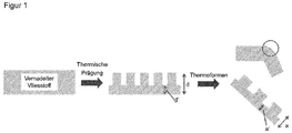
- a too low structuring depth leads to the nonwoven fabric being unsuitable for the thermoforming process, since local smoothing occurs in particular in the region of the edges. This effect is in FIG. 1 shown.
- the WO 0017435A1 describes moldable and durable fabrics and a process for making fabrics suitable for lamination to a contoured surface, such as a decorative layer in the headliner of an automobile or other vehicle.
- the textile fabric based on a nonwoven fabric is subjected to a stitchbonding process. After the Nähwirk intimid is the textile Heat treated sheet, resulting in a compression and shrinkage.
- a disadvantage of this method is that no pronounced 3D structuring can be achieved.
- the formed meshes show only a slightly formed structure.
- the invention is based on the object to provide a nonwoven fabric with pronounced 3-D structure, which is suitable for producing a decorative layer for the automotive interior.
- the nonwoven fabric should be processed in a thermoforming process without the 3-D structure is significantly smoothed.
- the invention is further based on the object to provide a method for producing such a nonwoven fabric and uses for him.
- thermoplastic fibers suitable for the production of a decorative interior lining
- the nonwoven fabric contains thermoplastic fibers, is needled and exhibits a maximum elongation of at least 30%
- the nonwoven fabric has embossed depressions at its base surfaces wherein the ratio between the thickness of the nonwoven fabric in the region of the base areas of the recesses and the thickness of the nonwoven fabric in the region of the unembossed regions is at most 0.1 and wherein the proportion of the total base area of the recesses on the total surface of the nonwoven fabric of 0.5% 30%.
- the nonwoven fabric according to the invention exhibits a pronounced 3-D structure, which is reflected in a ratio between the thickness of the nonwoven fabric in the area of the base areas of the recesses and the thickness of the nonwoven fabric in the area of the unembossed areas of 0.005 to 0.1.
- Embossed depressions are to be understood as meaning regions of the nonwoven which, at least on the surface, are partially fused and can be visually perceived as a depression.
- Unembossed areas are areas which have not been provided with an embossed pattern and therefore are not or only slightly thermally fused.
- the nonwoven fabric has a ratio between the thickness of the nonwoven fabric in the region of the base areas of the recesses and the thickness of the nonwoven fabric in the region of the unembossed regions of 0.005 to 0.1, preferably from 0.01 to 0.1, and in particular from 0.01 up to 0.05.
- the nonwoven fabric shows a high mechanical stability, which is shown in its maximum tensile strain of more than 30%, for example from 30% to 150%.
- the nonwoven fabric has an ultimate tensile elongation of from 40% to 150%, more preferably from 40% to 120%, and most preferably from 50% to 120%.
- the nonwoven fabric can be easily processed in a thermoforming process without causing tearing of the nonwoven fabric due to the elongation of the nonwoven fabric during the thermoforming process.
- a nonwoven fabric with such a pronounced 3D structure ie with such a large ratio between the thickness of the nonwoven fabric in the area of the base areas of the recesses and the thickness of the nonwoven fabric in the area of the unembossed areas, exhibits such high maximum elongation values.
- embossing to form such a pronounced 3D structure namely, the fibers in the nonwoven fabric are locally strongly compressed, to the formation of a polymer film as a conglomerate of many fibers.
- polymer films have lower ultimate elongation values than fibrous nonwovens, as these allow the fibers to move towards each other to some extent and yield in this way over a wide range of tensile elongation forces.
- the proportion of the total base area of the depressions on the total surface area of the nonwoven fabric is from 0.5% to 25%, preferably from 0.5% to 20%, more preferably from 0.5% to 15%, in particular from 0.5% to 10%.
- the maximum tensile elongation of the nonwoven fabric is at least 30%.
- This high mechanical stability of the nonwoven fabric can be achieved at least in part by using a needle-punched nonwoven fabric.
- nonwoven fabric according to the invention Due to its good mechanical properties of the nonwoven fabric according to the invention can be used without further layers, in particular without reinforcing layer. This allows a simple and inexpensive production.
- the nonwoven fabric has a Nadeleinstich Why from 10 / cm 2 to 2000 / cm 2 , preferably from 100 / cm 2 to 1000 / cm 2 and in particular from 200 / cm 2 to 600 / cm 2 .
- the high mechanical stability of the nonwoven fabric according to the invention is also reflected in that it withstands a high maximum tensile force, for example of more than 150 N / 5 cm, preferably from 200 N / 5 cm to 1000 N / 5 cm, more preferably 250 N / 5 cm to 1000 N / 5 cm, and in particular from 250 N / 5 cm to 600 N / 5 cm and / or abrasion, measured in accordance with JIS L 1096 of better than the grade 3, preferably better than the grade 4 may have ,
- the nonwoven fabric is preferably produced by using an embossing roll having an engraving depth of 0.1 mm to 2.5 mm, more preferably 0.25 mm to 2.0 mm, and especially 0.5 mm to 2.0 mm and a compression area of from 0.5% to 30%, more preferably from 0.5% to 25%, even more preferably from 0.5% to 20%, even more preferably from 0.5% to 15%, especially from 0, 5% to 10%.
- the nonwoven fabric is only partially embossed due to the large engraving depth of the embossing roller away from the embossed spot remain almost unaffected. Accordingly, according to the invention, the nonwoven fabric preferably has unembossed regions which are distinguished by the fact that they are not or only slightly thermally fused. Advantageously, the proportion of these unembossed areas is from 50 to 100%.
- the large engraving depth of the embossing roll also makes it possible to obtain the original thickness of the material away from the compressed areas. This is advantageous because it allows the Karschierfunktion the nonwoven fabric can be optimally utilized. In fact, commonly used automotive interior substrates often contain glass fibers that must be completely obscured.
- the recesses are ultrasonically embossed. This makes it particularly easy to achieve that the unembossed areas remain almost unaffected. At the same time enough energy can be introduced by the ultrasound at the wells despite large spatial proximity to achieve a filming of the fibers. In this way, a material with a high ratio between the thickness of the nonwoven fabric in the region of the base areas of the recesses and the thickness of the nonwoven fabric in the region of the unembossed areas and thus also a pronounced 3D structure can be obtained in a particularly defined manner. In addition, ultrasonically impressed cavities remain intact during thermal deformation or are only slightly modified to be imperceptible to the naked eye.
- the thermoplastic fibers are staple fibers.
- the staple fibers preferably have a fiber length of from 10 mm to 80 mm, more preferably from 20 mm to 60 mm, and especially from 30 mm to 60 mm.
- the embossed areas have an aspect ratio of 4: 1 to 1: 2, preferably 4: 1 to 1: 1, and more preferably 3: 1 to 1: 1. These aspect ratios make it possible to make the pronounced 3D structuring particularly appealing, whereby the selected pattern can be emphasized.
- the embossed areas of the nonwoven fabric have a depth of from 0.1 mm to 2.5 mm, more preferably from 0.25 mm to 2.0 mm, in particular from 0.5 mm to 2.0 mm. At these depths, the depressions are particularly visually and haptically detectable.
- thermoplastic fibers preferably in an amount of at least 50% by weight, for example from 50% by weight to 99% by weight, more preferably from 70% by weight to 95% by weight. , and in particular from 90% by weight to 95% by weight, based in each case on the total weight of the nonwoven fabric.
- thermoplastic fibers preferably in an amount of at least 50% by weight, for example from 50% by weight to 99% by weight, more preferably from 70% by weight to 95% by weight. , and in particular from 90% by weight to 95% by weight, based in each case on the total weight of the nonwoven fabric.
- thermoplastic fibers have a melting point of from 100 ° C to 300 ° C, more preferably from 150 ° C to 300 ° C, and especially from 200 ° C to 300 ° C.
- thermoplastic fibers which have proven particularly suitable are the polyesters, in particular polyethylene terephthalate, polybutylene terephthalate, polytrimethylene terephthalate, polylactide, polycaprolactone, polyamide, in particular polycaprolactam, polyamide-6,6, polyamide-11, polyamide-12, or polyolefin, in particular polypropylene, polyethylene, Containing polystyrene, and mixtures and / or copolymers thereof.
- polyesters in particular polyethylene terephthalate, polybutylene terephthalate, polytrimethylene terephthalate, polylactide, polycaprolactone, polyamide, in particular polycaprolactam, polyamide-6,6, polyamide-11, polyamide-12, or polyolefin, in particular polypropylene, polyethylene, Containing polystyrene, and mixtures and / or copolymers thereof.
- thermoplastic fibers advantageously exhibit a fiber denier of from 0.1 denier to 10 denier, more preferably from 1 denier to 6 denier, and more preferably from 1.5 denier to 4 denier. With these subtleties, the bulk and resilience of the fibers in conjunction with the desired softening can be achieved particularly well.
- the basis weight of the nonwoven fabric may also vary.
- basis weights in the range from 50 g / m 2 to 500 g / m 2 , more preferably from 100 g / m 2 to 300 g / m 2 , even more preferably from 100 g / m 2 to 250 g / m 2 are suitable , and in particular from 150 g / m 2 to 250 g / m 2 proved.
- the nonwoven fabric preferably has a thickness in the range from 0.25 mm to 2.5 mm, preferably from 0.5 mm to 2.5 mm, more preferably from 0.5 mm to 2.0 mm and in particular from 1.0 mm to 2.0 mm.
- the nonwoven fabric may preferably have a polymeric binder layer on at least one surface.
- This preferably contains polyacrylates, polystyrene, polyurethanes, polycarbonates, polyvinyl acetate-ethylene Copolymers, their mixtures and copolymers, in particular in a proportion of more than 90 wt.% Based on the total weight of the binder layer.
- the polymeric binder layer has a weight per unit area of from 5 g / m 2 to 50 g / m 2 , preferably from 5 g / m 2 to 40 g / m 2 , more preferably 5 g / m 2 to 30 g / m 2 .
- inventive method is particularly suitable for producing a nonwoven fabric according to the invention according to one or more of the embodiments described herein. Accordingly, the foregoing preferred embodiments described with regard to the nonwoven fabric according to the invention are also intended, mutatis mutandis, to refer to the method according to the invention as preferred embodiments.
- a needle-punched nonwoven fabric comprising thermoplastic fibers is provided or manufactured.
- the nonwoven fabric having a high maximum tensile force can be obtained.
- the needle punching is performed so that a needle drop density of 10 / cm 2 to 2000 / cm 2 , preferably from 100 / cm 2 to 1000 / cm 2 and in particular from 200 / cm 2 to 600 / cm 2 is achieved.
- the production of the unembossed nonwoven fabric can be carried out in the usual ways known to the person skilled in the art. If, as preferred according to the invention, staple fibers are used, they are expediently first carded and laid to form a nonwoven. This may be followed by thermal pre-consolidation followed by the needling step.
- the proportion of the total base area of the recesses on the total area of the nonwoven fabric is adjusted to 0.5% to 30%. This can be achieved by suitable selection of the welding surface of the embossing roller. Accordingly, this is preferably also from 0.5% to 30%.
- embossed depressions are imparted to the nonwoven fabric having bases at their bottom, the ratio between the thickness of the nonwoven fabric in the region of the bases of the depressions and the thickness of the nonwoven fabric in the region of the unembossed regions being at most 0.1. This can be achieved by adjusting the engraving depth of the embossing roller.
- heated embossing rollers are used, for example with a temperature of 180 ° C to 240 ° C. These advantageously have an engraving depth of 0.1 mm to 2.5 mm.
- the embossing is carried out with an embossing roller having an engraving depth which corresponds at least to the thickness of the nonwoven fabric in the region of the unembossed regions. This is advantageous because the unembossed areas are not pressed in this way, which has a positive effect on the optical and mechanical properties of the nonwoven fabric.
- embossing of the nonwoven fabric is carried out as ultrasonic embossing. Due to the ultrasound thermoplastic materials can be excited and melted, which allows the introduction of embossed patterns.
- the energy can be introduced via the high-frequency excitation of an ultrasonic anvil during ultrasound embossing. This is advantageous because it works in this way at significantly lower temperatures and the energy can be targeted to the desired areas of the nonwoven fabric registered.
- the adjustment of the specific ratio between the thickness of the nonwoven fabric in the region of the embossed regions and the unembossed regions can be carried out particularly uniformly, reproducibly and accurately.
- ultrasound embossing is particularly process-stable. Another significant advantage of this method is that the unembossed areas are particularly little affected, ie neither pressed nor melted, which has a positive effect on the optical and mechanical properties of the nonwoven fabric.
- Another object of the invention is a thermally embossed nonwoven produced by a method according to one or more of the aforementioned embodiments.
- the nonwoven fabric according to the invention according to one or more of the described embodiments is outstandingly suitable for the production of a decorative layer for the car interior because it combines a pronounced 3-D structure with a good mechanical stability and in particular a good thermoformability.
- the nonwoven fabric is used to produce a headliner for the interior of the car.
- a further embodiment of the invention comprises a thermoformed nonwoven fabric according to the invention according to one or more of the described embodiments.
- the nonwoven fabric after thermoforming, has indentations imprinted around its edge at an angle of 90 ° in the area of the deformation, the bases having base areas, the ratio between the thickness of the nonwoven fabric in the area of the base areas of the recesses and the thickness of the recess Non-woven fabric in the range of unembossed areas is not more than 0.1.
- FIG. 1 d shows the thickness of the nonwoven fabric in the region of the unembossed regions and d 'the thickness of the nonwoven fabric in the region of the base surfaces of the recesses, in each case before the thermoforming process, and a and a' the corresponding thicknesses after the thermoforming process.
- this causes Thermoforming, especially at the edges of a local smoothing of the 3-D structure.
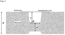
- FIG. 2 shows a cross section of the nonwoven fabric according to the invention.
- Thickness of the nonwoven fabric in the area of the base areas of the embossed recesses A cross-section of the nonwoven fabric is prepared using a scalpel. Care must be taken that this covers at least 5 wells. Alternatively, several cross sections can be prepared. Subsequently, the thickness of the nonwoven fabric in the area of the base areas of the recesses (in FIG. 2 referred to as d ') with a suitable microscope, preferably measured with an electron microscope. The measurement is carried out for at least 5 different wells and at least 3 digits per well.
- Thickness of the nonwoven fabric in the area of unembossed areas Measurement according to test specification according to DIN EN ISO 9073-2.
- Basis weight Measurement according to test specification according to EN 29073 - T1. In each case 3 100 ⁇ 100 mm samples are punched out for the determination of the basis weights, the samples are weighed and an average value is formed.
- Depth of the embossed areas A cross-section of the nonwoven fabric is prepared using a scalpel. Care must be taken that this covers at least 5 wells. Alternatively, several cross sections can be prepared. Subsequently, the depth of the embossed areas (in FIG. 2 characterized as t) as the vertical distance between a theoretical line (see FIG. 2 ) at the level of the surface of the unembossed areas and the base of the recesses (in FIG. 2 characterized as b) determined by electron microscopy. In each case at least 5 embossed areas, each measured at least 3 places per embossed area.
- a cross-section of the nonwoven fabric is prepared using a scalpel. Care must be taken to ensure that it has at least 5 wells at its widest point. Alternatively, several cross sections can be prepared. Subsequently, the diameter of the recesses is determined on the base (in FIG. 2 designated as b). In each case at least 5 embossed areas are measured and an average value is formed. The aspect ratio results from the ratio of the depth (in FIG. 2 referred to as t) and the measured diameter of the base.
- Percentage of the total area of the depressions on the total area of the nonwoven fabric First, the diameter of the base area of the depressions is measured. At the widest point of the embossed areas (in FIG. 2 referred to as b) is determined by 5 embossed areas and an average is formed. On the basis of this value, taking into account the geometry, the area of the embossed areas is determined and the proportion to the total area of the nonwoven fabric is calculated.
- thermoplastic fibers Measurement according to test specification according to DIN EN ISO 11357-3 with a heating rate of 10 ° C / min.
Landscapes
- Engineering & Computer Science (AREA)
- Mechanical Engineering (AREA)
- Textile Engineering (AREA)
- Vehicle Interior And Exterior Ornaments, Soundproofing, And Insulation (AREA)
- Nonwoven Fabrics (AREA)
- Laminated Bodies (AREA)
- Lining Or Joining Of Plastics Or The Like (AREA)
Abstract
Description
- Die Erfindung betrifft einen thermisch geprägten Vliesstoff. Die Erfindung betrifft ferner ein Verfahren zu seiner Herstellung sowie seine Verwendung zur Herstellung einer Dekorschicht für den Automobilinnenraum.
- Der Automobilinnenraum wird heutzutage fast ausschließlich mit textilen Flächengebilden als Dekorschicht ausgekleidet. Dies dient in erster Linie einer positiven optischen Wahrnehmung und vermittelt den Personen im Innenraum verglichen mit glatten Strukturen aus Metall oder Plastik ein angenehmeres Raumgefühl. Dazu kommt, dass textile Flächengebilde eine geringere Schallreflektion und eine größere Schallabsorption als glatte oder harte Materialien haben.
- Im Bereich der textilen Flächengebilde werden insbesondere Gewebe, Gewirke sowie Vliesstoffe eingesetzt, wobei Gewebe aufgrund ihrer Hochpreisigkeit heutzutage praktisch nicht mehr zu finden sind. Gewirke dagegen werden aufgrund der Möglichkeit auch sehr feine Strukturen zu realisieren sehr häufig verwendet. Allerdings findet sich hier meist nur der Einbau mit mindestens einer Zusatzlage, häufig einem weichem Schaum, als untere Schicht, da die feinstrukturierten Materialien allein zu anfällig für Beschädigungen wären und als solche auf hartem Untergrund auch keine guten Abrasionsbeständigkeiten gegenüber Abrieb zeigen. Zusätzlich sind Gewirke recht anfällig für die Penetration von Klebstoffen mit deren Hilfe in der Regel die Befestigung im Innenraum vorgenommen wird.
- Vliesstoffe hingegen können problemlos auch ohne Zusatzlage als Dekor eingesetzt werden, weil sie eine hohe Gleichmäßigkeit, bei hoher Dicke und Belegungsdichte der Oberfläche mit Fasern aufweisen. Als besonders geeignet haben sich dabei kardierte, quergelegte Vliesstoffe erwiesen, die aus thermoplastischen Fasern bestehen. Der Kardierprozess mit anschließender Querlegung erzeugt dabei die nötige Ausrichtung der Fasern und ihre grundsätzliche Verbindung zueinander zu einem Vliesstoff. Die thermoplastischen Fasern erlauben später die zur Anpassung an den Automobilinnenraum notwendige thermische Verformbarkeit und sorgen dadurch für eine gute Verarbeitbarkeit in den Prozessschritten der Herstellung des Dachhimmels.
- Um ausreichende mechanische Festigkeit bei gleichzeitig guter mechanischer Verformbarkeit mit hohen lokalen Dehnungswerten, wie sie beim Thermoformen auftreten (Größenordnung von bis zu 60 %) zu gewährleisten, wird nach dem Kardierprozess mit anschließender Querlegung in einem Vernadelungsprozess mechanisch verfestigt. Auf diese Weise können die notwendigen Zugfestigkeiten und Höchstzugdehnungswerte entsprechend erreicht werden.
- Die Oberfläche bei rein mechanisch verfestigten Vliesstoffen ist jedoch noch relativ anfällig für Beschädigungen. Daher wird nach der mechanischen Verfestigung zusätzlich eine chemische Verfestigung durchgeführt. Hierbei werden mit Hilfe eines polymeren Binders die Fasern vor allem auf der Oberfläche miteinander verbunden.
- Auf diese Weise hergestellte Vliesstoffe des Stands der Technik weisen, bis auf eine geringfügige und meist ungeordnete Strukturierung durch die Nadeleinstiche kein Relief auf. In diesem Aspekt ist der Vliesstoff bislang den Gewirken unterlegen, welche inhärent eine regelmäßige mit dem Auge sichtbare 3D-Struktur besitzen. Es hat sich jedoch gezeigt, dass das Vorhandensein von sichtbaren 3D-Strukturen im Innenraum von Automobilen immer wichtiger wird, da derartige Strukturen den Automobilinnenraum optisch vergrößern können. Dieser Effekt kommt insbesondere beim beschränkten Raum im Automobil zu tragen. Gerade durch den Einsatz immer dickerer Isolierschichten zur Schall- und Wärmeisolation, aber auch durch das Verwenden immer mehr sicherheitsrelevanter Bauteile wie Airbags wird der Innenraum nämlich zunehmend beschränkt. Eine Vergrößerung des gesamten Automobils hat in den letzten Jahren bereits stattgefunden, stößt aber immer mehr an gesetzliche (Straßenverkehrsordnung), sowie auch bauliche Grenzen (Straßenbreite, Parkplatzbreite) und wird damit auch vom Kunden nicht mehr weiter gewünscht. Die 3D-Strukturierung von Oberflächen im Automobilinnenraum ermöglicht es nun trotz des beschränkten Raumes ein Gefühl von großzügiger Raumgestaltung zu vermitteln. Zu diesem Zweck bietet sich insbesondere der Dachhimmel an, da er eine große Fläche einnimmt, so dass durch entsprechende Strukturierung der Automobilinnenraum besonders effektiv optisch vergrößert werden kann.
- Um den Eindruck einer 3D-strukturierten Oberfläche zu erzeugen werden Vliesstoffe oftmals mit einer bestimmten Musterung bedruckt, die einen optischen 3-D Effekt hervorruft. Dieser rein optische Effekt wird jedoch oftmals als nicht ausreichend betrachtet, da er vom Kunden bei genauerer Betrachtung als "Täuschung" angesehen wird. Erwünscht ist dagegen die Haptik und Optik einer echten 3D-Strukturierung, die als besonders hochwertig empfunden wird.
- Die
US 6737114B2 beschreibt einen Vliesstoff, der eine dreidimensionale gedruckte Oberfläche aufweist, die durch Siebdrucken des Gewebes mit einem "Puff-Pigment" erreicht wird. Diese Methode ist allerdings limitiert in der Ausprägung der 3D-Struktur im Bezug auf Schärfe und Konturtiefe. Dabei gilt, je höher die Kontur desto geringer die Schärfe der 3D-Strukturierung. - Ebenfalls bekannt ist es Vliesstoffe zur Erzeugung eines 3-D Effekts mit einem Heissprägungsmuster zu versehen. Hierzu werden in der Regel erhitzte strukturierte Kalanderwalzen eingesetzt. Die mit diesem Verfahren in herkömmlicher Weise hergestellten Vliesstoffe zeigen jedoch verschiedene Nachteile. So haben diese Vliesstoffe entweder keine ausreichende Strukturierungstiefe oder es sind zu stark verpresste, papierartige Vliesstoffe mit mangelnder Höchstzugdehnung und damit auch mangelnder Thermoformbarkeit.
- Auch eine zu geringe Strukturierungstiefe führt dazu, dass der Vliesstoff für den Thermoformingprozess ungeeignet ist, da dabei insbesondere im Bereich der Kanten lokale Glättungen auftreten. Dieser Effekt ist in
Figur 1 gezeigt. - Die
WO 0017435A1 - Der Erfindung liegt die Aufgabe zu Grunde einen Vliesstoff mit ausgeprägter 3-D Struktur bereitzustellen, der sich zur Herstellung einer Dekorschicht für den Automobilinnenraum eignet. Der Vliesstoff soll dabei in einem Thermoformingprozess verarbeitet werden können ohne dass die 3-D Struktur signifikant geglättet wird. Der Erfindung liegt ferner die Aufgabe zu Grunde ein Verfahren zur Herstellung eines derartigen Vliesstoffs bereitzustellen sowie Verwendungen für ihn.
- Diese Aufgabe wird gelöst durch einen thermisch geprägten Vliesstoff, geeignet zur Herstellung einer Dekorschicht für den Autoinnenraum, wobei der Vliesstoff thermoplastische Fasern enthält, vernadelt ist und eine Höchstzugdehnung von mindestens 30 % zeigt, und wobei der Vliesstoff eingeprägte Vertiefungen aufweist, die an ihrem Grund Grundflächen aufweisen, wobei das Verhältnis zwischen der Dicke des Vliesstoffs im Bereich der Grundflächen der Vertiefungen und der Dicke des Vliesstoffs im Bereich der ungeprägten Bereiche höchstens 0,1 beträgt und wobei der Anteil der Gesamtgrundfläche der Vertiefungen an der Gesamtfläche des Vliesstoffs von 0,5 % bis 30 % beträgt.
- Der erfindungsgemäße Vliesstoff zeigt eine ausgeprägte 3-D Struktur, die sich in einem Verhältnis zwischen der Dicke des Vliesstoffs im Bereich der Grundflächen der Vertiefungen und der Dicke des Vliesstoffs im Bereich der ungeprägten Bereiche von 0,005 bis 0,1 widerspiegelt.
- Unter eingeprägten Vertiefungen sind Bereiche des Vliesstoffs zu verstehen, die zumindest an der Oberfläche teilweise verschmolzen vorliegen und visuell als Vertiefung wahrgenommen werden können. Unter ungeprägten Bereichen sind Bereiche zu verstehen, die nicht mit einem Prägemuster versehen wurden und deshalb nicht oder nur geringfügig thermisch verschmolzen vorliegen.
- Aus diesem Grund kann die 3-D Struktur auch beim Verformen in einem Thermoformingprozess in einem Maße erhalten werden, dass sie beispielsweise den Automobilinnenraum sehr effektvoll optisch vergrößern kann. Vorzugsweise weist der Vliesstoff ein Verhältnis zwischen der Dicke des Vliesstoffs im Bereich der Grundflächen der Vertiefungen und der Dicke des Vliesstoffs im Bereich der ungeprägten Bereiche von 0,005 bis 0,1, bevorzugt von 0,01 bis 0,1, und insbesondere von 0,01 bis 0,05 auf.
- Gleichzeitig zeigt der Vliesstoff eine hohe mechanische Stabilität, was sich in seiner Höchstzugdehnung von mehr als 30 %, beispielsweise von 30 % bis 150 % zeigt. Vorzugsweise weist der Vliesstoff eine Höchstzugdehnung von 40 % bis 150 %, noch bevorzugter von 40 % bis 120 %, und insbesondere von 50 % bis 120 % auf. Hierdurch kann der Vliesstoff problemlos in einem Thermoformingprozess verarbeitet werden, ohne dass es zu einem Reißen des Vliesstoffs aufgrund der beim Thermoformingprozess auftretenden Dehnung des Vliesstoffs kommt. Es war überraschend, dass ein Vliesstoff mit einer derart ausgeprägten 3D-Struktur, d.h. mit einem derart großen Verhältnis zwischen der Dicke des Vliesstoffs im Bereich der Grundflächen der Vertiefungen und der Dicke des Vliesstoffs im Bereich der ungeprägten Bereiche so gute Höchstzugdehnungswerte zeigt. Durch das Prägen unter Ausbildung einer derart ausgeprägten 3D-Struktur werden die Fasern im Vliesstoff nämlich lokal stark zusammengepresst, bis hin zur Bildung eines Polymerfilms als Konglomerat aus vielen Fasern. Polymerfilme weisen jedoch schlechtere Höchstzugdehnungswerte als aus Fasern bestehende Vliesstoffe auf, da sich bei diesen die Fasern in gewissem Maße gegeneinander bewegen und auf diese Art und Weise in einem großen Bereich angelegten Zugdehnungskräften nachgeben können. Überraschend sind hohe Höchstzugdehnungswerte auch mit dem erfindungsgemäßen Vliesstoff möglich, trotz der ausgeprägten 3D-Strukturierung. Ohne sich auf einen Mechanismus festzulegen, wird vermutet, dass dies durch die Einstellung des Anteils der Gesamtgrundfläche der Vertiefungen an der Gesamtfläche des Vliesstoffs auf höchstens 30 % gelingt. Dadurch dass die Gesamtgrundfläche der Vertiefungen nur einen geringen Anteil an der Gesamtfläche des Vliesstoffs einnimmt, fällt die Verschlechterung der Höchstzugdehnung durch die geprägten Bereiche nicht wesentlich ins Gewicht.
- In einer bevorzugten Ausführungsform der Erfindung beträgt der Anteil der Gesamtgrundfläche der Vertiefungen an der Gesamtfläche des Vliesstoffs von 0,5 % bis 25 %, vorzugsweise von 0,5 % bis 20 %, noch bevorzugter von 0,5 % bis 15 % , insbesondere von 0,5 % bis 10 %.
- Erfindungsgemäß beträgt die Höchstzugdehnung des Vliesstoffs mindestens 30 %. Diese hohe mechanische Stabilität des Vliesstoffs kann zumindest teilweise dadurch erzielt werden, dass ein vernadelter Vliesstoff eingesetzt wird.
- Aufgrund seiner guten mechanischen Eigenschaften kann der erfindungsgemäße Vliesstoff ohne weitere Lagen, insbesondere ohne Verstärkungslage eingesetzt werden. Dies ermöglicht eine einfache und kostengünstige Herstellung.
- Besonders gute Festigkeiten haben sich gezeigt, wenn der Vliesstoff eine Nadeleinstichdichte von 10 /cm2 bis 2000 /cm2, vorzugsweise von 100 /cm2 bis 1000 /cm2 und insbesondere von 200 /cm2 bis 600 /cm2 aufweist.
- Die hohe mechanische Stabilität des erfindungsgemäßen Vliesstoffs spiegelt sich auch darin, dass er einer hohen Höchstzugkraft standhält, beispielsweise von mehr als 150 N/5 cm, bevorzugt von 200 N/5 cm bis 1000 N/5 cm, noch bevorzugter von 250 N/5 cm bis 1000 N/5 cm, und insbesondere von 250 N/5 cm bis 600 N/5 cm und/oder einen Abrieb, gemessen in Anlehnung an JIS L 1096 von besser als der Note 3, bevorzugt besser als der Note 4 aufweisen kann.
- Diese Kombination einer ausgeprägten 3-D Struktur und gleichzeitig hohen mechanischen Stabilität kann erfindungsgemäß dadurch erhalten werden, dass das thermische Prägen des Vliesstoffs mit einer Prägewalze durchgeführt wird, die eine Gravurtiefe von mindestens der Dicke des ungeprägten Vliesstoffs in Kombination mit einer vergleichsweise geringen Verpressfläche aufweist. Erfindungsgemäß bevorzugt wird der Vliesstoff unter Verwendung einer Prägewalze hergestellt, die eine Gravurtiefe von 0,1 mm bis 2,5 mm, noch bevorzugter von 0,25 mm bis 2,0 mm, und insbesondere von 0,5 mm bis 2,0 mm, und eine Verpressfläche von 0,5 % bis 30 %, noch bevorzugter von 0,5 % bis 25 %, noch bevorzugter von 0,5 % bis 20 %, noch bevorzugter von 0,5 % bis 15 %, insbesondere von 0,5 % bis 10 % aufweist. Dabei ist unter Gravurtiefe die Höhe der Prägeprotrusionen zu verstehen. Weist die Gravurwalze Protrusionen unterschiedlicher Höhe auf, so entspricht die Gravurtiefe der Höhe der maximalen Protrusion. Unter der Verpressfläche ist der Anteil der Fläche der Prägewalze zu verstehen, der sich aus der Summe der Plateauflächen der Protrusionen ergibt. Ohne sich erfindungsgemäß auf einen Mechanismus festzulegen wird vermutet, dass durch die große Gravurtiefe der Prägewalze der Vliesstoff nur teilweise geprägt wird, Bereiche abseits der geprägten Stelle bleiben annähernd unbeeinflusst. Dementsprechend weist der Vliesstoff erfindungsgemäß bevorzugt ungeprägte Bereiche auf, die sich dadurch auszeichnen, dass sie nicht oder nur geringfügig thermisch verschmolzen sind. Vorteilhafterweise beträgt der Anteil dieser ungeprägten Bereiche von 50 bis 100 %.
- Die große Gravurtiefe der Prägewalze ermöglicht es ferner abseits der verpressten Stellen die Originaldicke des Materials zu erhalten. Dies ist vorteilhaft, da hierdurch die Karschierfunktion des Vliesstoffs optimal ausgenutzt werden kann. Oftmals enthalten nämlich üblicherweise verwendete Substrate im Automobilinnenraum Glasfasern, die vollständig verdeckt werden müssen.
- Die Verwendung von Prägewalzen mit großer Gravurtiefe, d.h. von mindestens der Dicke des ungepägten Vliesstoffs ist unüblich, da aufwendige Maßnahmen, beispielsweise langsame Prozessführung, getroffen werden müssen um eine Perforation auszuschließen.
- Erfindungsgemäß besonders bevorzugt sind die Vertiefungen ultraschallgeprägt. Hierdurch kann besonders leicht erreicht werden, dass die ungeprägten Bereiche annähernd unbeeinflusst verbleiben. Gleichzeitig kann durch den Ultraschall an den Vertiefungen trotz großer räumlicher Nähe genug Energie eingebracht werden um eine Verfilmung der Fasern zu erreichen. Hierdurch kann besonders definiert ein Material mit großem Verhältnis zwischen der Dicke des Vliesstoffs im Bereich der Grundflächen der Vertiefungen und der Dicke des Vliesstoffs im Bereich der ungeprägten Bereiche und damit auch eine ausgeprägte 3D-Struktur erhalten werden. Darüber hinaus bleiben ultraschallgeprägte Vertiefungen beim thermischen Verformen intakt oder werden nur so geringfügig verändert, dass es mit dem bloßen Auge nicht wahrnehmbar ist.
- Bevorzugt sind die thermoplastischen Fasern Stapelfasern. Die Stapelfasern weisen vorzugsweise eine Faserlänge von 10 mm bis 80 mm, noch bevorzugter von 20 mm bis 60 mm, und insbesondere von 30 mm bis 60 mm auf.
- Vorteilhafter Weise zeigen die geprägten Bereiche ein Aspektverhältnis von 4:1 bis 1:2, bevorzugt von 4:1 bis 1:1, und insbesondere von 3:1 bis 1:1. Diese Aspektverhältnisse ermöglichen es die ausgeprägte 3D-Strukturierung besonders ansprechend zu gestalten wodurch die gewählte Musterung hervorgehoben werden kann.
- Ebenfalls vorteilhafterweise zeigen die geprägten Bereiche des Vliesstoffs eine Tiefe von 0,1 mm bis 2,5 mm, noch bevorzugter von 0,25 mm bis 2,0 mm, insbesondere von 0,5 mm bis 2,0 mm. Bei diesen Tiefen sind die Vertiefungen besonders gut visuell und haptisch detektierbar.
- Um die thermische Prägbarkeit des Vliesstoffs zu ermöglichen weist dieser vorzugsweise thermoplastische Fasern auf, bevorzugt in einer Menge von mindestens 50 Gew.%, beispielsweise von 50 Gew.% bis 99 Gew.%, noch bevorzugter von 70 Gew.% bis 95 Gew.%, und insbesondere von 90 Gew.% bis 95 Gew.% jeweils bezogen auf das Gesamtgewicht des Vliesstoffs. Vorteilhaft an der Verwendung thermoplastischer Fasern ist ferner, dass diese gleichzeitig das Thermoformen ermöglichen. Vorteilhafterweise weisen die thermoplastischer Fasern einen Schmelzpunkt von 100 °C bis 300 °C, noch bevorzugter von 150 °C bis 300 °C, und insbesondere von 200 °C bis 300 °C auf. Durch den Einsatz derartiger thermoplastischer Fasern kann eine gute Stabilität der Materialien in der Anwendung bei gleichzeitig guter Verarbeitbarkeit optimal kombiniert werden.
- Es können die verschiedensten thermoplastischen Fasern eingesetzt werden. Als besonders geeignet haben sich thermoplastische Fasern erwiesen, die Polyester, insbesondere Polyethylenterephthalat, Polybutylenterephthalat, Polytrimethylenterephthalat, Polylactid, Polycaprolacton, Polyamid, insbesondere Polycaprolactam, Polyamid-6,6, Polyamid-11, Polyamid-12, oder Polyolefin, insbesondere Polypropylen, Polyethylen, Polystyrol enthalten, sowie Gemische und/oder Copolymere hiervon.
- Die thermoplastischen Fasern zeigen vorteilhafter Weise einen Fasertiter von 0,1 denier bis 10 denier, noch bevorzugter von 1 denier bis 6 denier, und insbesondere von 1,5 denier bis 4 denier. Mit diesen Feinheiten kann die Bauschigkeit und das Rückstellvermögen der Fasern in Zusammenhang mit dem gewünschten Weichgriff besonders gut erzielt werden.
- Das Flächengewicht des Vliesstoffs kann ebenfalls variieren. Als geeignet haben sich beispielsweise Flächengewichte im Bereich von 50 g/m2 bis 500 g/m2, noch bevorzugter von 100 g/m2 bis 300 g/m2, noch bevorzugter von 100 g/m2 bis 250 g/m2, und insbesondere von 150 g/m2 bis 250 g/m2 erwiesen. Mit diesen Flächengewichten kann sowohl die gewünschte Dicke zur vollständigen Abdeckung des unterliegenden Substrats, sowie auch die nötige Höchstzugdehnung für den Thermoformingschritt besonders gut erzielt werden.
- Erfindungsgemäß bevorzugt weist der Vliesstoff eine Dicke im Bereich von 0,25 mm bis 2,5 mm, bevorzugt von 0,5 mm bis 2,5 mm, noch bevorzugter von 0,5 mm bis 2,0 mm und insbesondere von 1,0 mm bis 2,0 mm auf.
- Zur Verbesserung der Einbindung der Fasern an der Oberfläche (Abrasionsfähigkeit) kann der Vliesstoff vorzugsweise auf mindestens einer Oberfläche eine polymere Binderschicht aufweisen. Diese enthält bevorzugt Polyakrylate, Polystyrol, Polyurethane, Polycarbonate, Polyvinylacetat-Ethylen Copolymere, deren Gemische und Copolymere, insbesondere in einem Anteil von mehr als 90 Gew.% bezogen auf das Gesamtgewicht der Binderschicht.
- Zu diesem Zweck hat es sich als günstig erwiesen, wenn die polymere Binderschicht ein Flächengewicht von 5 g/m2 bis 50 g/m2, vorzugsweise von 5 g/m2 bis 40 g/m2, noch bevorzugter von 5 g/m2 bis 30 g/m2 aufweist.
- Ein weiterer Gegenstand der vorliegenden Erfindung betrifft ein Verfahren zur Herstellung eines thermisch geprägten Vliesstoffs mit einer Höchstzugdehnung von mindestens 30 %, geeignet als Dekorschicht für den Autoinnenraum, umfassend folgende Schritte:
- Bereitstellen eines vernadelten Vliesstoffs, umfassend thermoplastische Fasern,
- Thermisches Prägen des Vliesstoffs derart, dass dem Vliesstoff eingeprägte Vertiefungen verliehen werden, die an ihrem Grund Grundflächen aufweisen, wobei das Verhältnis zwischen der Dicke des Vliesstoffs im Bereich der Grundflächen der Vertiefungen und der Dicke des Vliesstoffs im Bereich der ungeprägten Bereiche höchstens 0,1 beträgt, und wobei der Anteil der Gesamtgrundfläche der Vertiefungen an der Gesamtfläche des Vliesstoffs von 0,5 % bis 30 % beträgt.
- Das erfindungsgemäße Verfahren eignet sich insbesondere zur Herstellung eines erfindungsgemäßen Vliesstoffs gemäß einer oder mehrerer der hier beschriebenen Ausführungsformen. Mithin sollen die vorangehenden im Hinblick auf den erfindungsgemäßen Vliesstoff beschriebenen bevorzugten Ausführungsformen mutatis mutandis sich als bevorzugte Ausführungsformen auch auf das erfindungsgemäße Verfahren beziehen.
- Im ersten Verfahrensschritt wird ein vernadelter Vliesstoff, umfassend thermoplastische Fasern bereitgestellt bzw. hergestellt. Durch die Verwendung eines vernadelten Vliesstoffs kann der Vliesstoff mit hoher Höchstzugkraft erhalten werden.
- In einer bevorzugten Ausführungsform wird die Vernadelung so durchgeführt, dass eine Nadeleinstichdichte von 10 /cm2 bis 2000 /cm2, vorzugsweise von 100 /cm2 bis 1000 /cm2 und insbesondere von 200 /cm2 bis 600 /cm2 erreicht wird.
- Die Herstellung des ungeprägten Vliesstoffs kann auf die üblichen, dem Fachmann bekannten Arten und Weisen erfolgen. Werden, wie erfindungsgemäß bevorzugt, Stapelfasern eingesetzt, so werden diese zweckmäßigerweise zunächst kardiert und zu einem Vlies gelegt. Hieran kann sich eine thermische Vorverfestigung gefolgt von dem Vernadelungschritt anschließen.
- Beim thermischen Prägen wird der Anteil der Gesamtgrundfläche der Vertiefungen an der Gesamtfläche des Vliesstoffs auf 0,5 % bis 30 % eingestellt. Dies kann über geeignete Auswahl der Verschweißfläche der Prägewalze erreicht werden. Diese beträgt dementsprechend vorzugsweise ebenfalls von 0,5 % bis 30 %.
- Beim thermischen Prägen werden ferner dem Vliesstoff eingeprägte Vertiefungen verliehen, die an ihrem Grund Grundflächen aufweisen, wobei das Verhältnis zwischen der Dicke des Vliesstoffs im Bereich der Grundflächen der Vertiefungen und der Dicke des Vliesstoffs im Bereich der ungeprägten Bereiche höchstens 0,1 beträgt. Dies kann über eine Einstellung der Gravurtiefe der Prägewalze erreicht werden.
- Vorzugsweise werden beheizte Prägewalzen eingesetzt, beispielsweise mit einer Temperatur von 180 °C bis 240 °C. Diese weisen vorteilhafterweise eine Gravurtiefe von 0,1 mm bis 2,5 mm auf. In einer weiteren bevorzugten Ausführungsform wird das Prägen mit einer Prägewalze durchgeführt, die eine Gravurtiefe aufweist, die mindestens der Dicke des Vliesstoffs im Bereich der ungeprägten Bereiche entspricht. Dies ist vorteilhaft, da die ungeprägten Bereiche so nicht verpresst werden, was sich positiv auf die optischen und mechanischen Eigenschaften des Vliesstoffs auswirkt.
- In einer besonders bevorzugten Ausführungsform der Erfindung wird das Prägen des Vliesstoffs als Ultraschallprägen durchgeführt. Durch den Ultraschall können thermoplastische Materialien angeregt und aufgeschmolzen werden, was das Einbringen von Prägemustern ermöglicht.
- Im Unterschied zu der Verwendung beheizter Prägewalzen, kann beim Ultraschallprägen die Energie über die hochfrequente Anregung eines Ultraschallamboss eingebracht werden. Dies ist vorteilhaft, da auf diese Weise mit deutlich niedrigeren Temperaturen gearbeitet werden und die Energie zielgerichtet an die gewünschten Bereiche des Vliesstoffs eingetragen werden kann. Hierdurch kann die Einstellung des spezifischen Verhältnisses zwischen der Dicke des Vliesstoffs im Bereich der geprägten Bereiche und der ungeprägten Bereiche besonders gleichmäßig, reproduzierbar und genau durchgeführt werden. Darüber hinaus ist das Ultraschallprägen besonders prozessstabil. Ein weiterer wesentlicher Vorteil dieses Verfahrens ist, dass die ungeprägten Bereiche hier besonders wenig beeinflusst, d.h. weder verpresst noch angeschmolzen werden, was sich positiv auf die optischen und mechanischen Eigenschaften des Vliesstoffs auswirkt.
- Ein weiterer Gegenstand der Erfindung ist ein thermisch geprägter Vliesstoff herstellbar mit einem Verfahren gemäß einer oder mehreren der vorgenannten Ausführungsformen.
- Der erfindungsgemäße Vliesstoff gemäß einer oder mehreren der beschriebenen Ausführungsformen eignet sich hervorragend zur Herstellung einer Dekorschicht für den Autoinnenraum, da er eine ausgeprägte 3-D Struktur mit einer guten mechanischen Stabilität und insbesondere einer guten Thermoverformbarkeit kombiniert. Erfindungsgemäß besonders bevorzugt wird der Vliesstoff zur Herstellung eines Dachhimmels für den Autoinnenraum eingesetzt.
- Eine weitere Ausführungsform der Erfindung umfasst einen thermoverformten erfindungsgemäßen Vliesstoff gemäß einer oder mehreren der beschriebenen Ausführungsformen.
- In einer bevorzugten Ausführungsform zeigt der Vliesstoff nach einem Thermoformen um eine Kante mit einem Winkel von 90 im Bereich der Verformung eingeprägte Vertiefungen, die an ihrem Grund Grundflächen aufweisen, wobei das Verhältnis zwischen der Dicke des Vliesstoffs im Bereich der Grundflächen der Vertiefungen und der Dicke des Vliesstoffs im Bereich der ungeprägten Bereiche höchstens 0,1 beträgt.
- In
Figur 1 zeigt d die Dicke des Vliesstoffs im Bereich der ungeprägten Bereiche und d' die Dicke des Vliesstoffs im Bereich der Grundflächen der Vertiefungen, jeweils vor dem Thermoformingprozess, und a und a' die entsprechenden Dicken nach dem Thermoformingprozess. Wie aus dem in Vergrößerung dargestellten eingekreisten Bereich ersichtlich, verursacht das Thermoformen insbesondere an den Kanten eine lokale Glättung der 3-D Struktur. -
Figur 2 zeigt einen Querschnitt des erfindungsgemäßen Vliesstoffs. - Die in der vorliegenden Beschreibung angegebenen Parameter werden wie folgt bestimmt:
Höchstzugdehnung: Messung nach Prüfvorschrift gemäß DIN EN 29073-3, bei einer Verformungsgeschwindigkeit von 200 mm/min. - Höchstzugkraft: Messung nach Prüfvorschrift gemäß DIN EN 29073-3, bei einer Verformungsgeschwindigkeit von 200 mm/min.
- Dicke des Vliesstoffs im Bereich der Grundflächen der eingeprägten Vertiefungen: Mithilfe eines Skalpells wird ein Querschnitt des Vliesstoffs präpariert. Dabei ist darauf zu achten, dass dieser mindestens 5 Vertiefungen umfasst. Alternativ können auch mehrere Querschnitte präpariert werden. Anschließend wird die Dicke des Vliesstoffs im Bereich der Grundflächen der Vertiefungen (in
Figur 2 bezeichnet als d') mit einem geeigneten Mikroskop, vorzugweise mit einem Elektronenmikroskop gemessen. Die Messung wird für mindestens 5 verschiedene Vertiefungen und an jeweils mindestens 3 Stellen pro Vertiefung durchgeführt. - Dicke des Vliesstoffs im Bereich der ungeprägten Bereiche: Messung nach Prüfvorschrift gemäß DIN EN ISO 9073-2.
- Flächengewicht: Messung nach Prüfvorschrift gemäß EN 29073 - T1. Es werden für die Bestimmung der Flächengewichte jeweils 3 100x100 mm große Proben ausgestanzt, die Proben gewogen und ein Mittelwert gebildet.
- Tiefe der geprägten Bereiche: Mithilfe eines Skalpells wird ein Querschnitt des Vliesstoffs präpariert. Dabei ist darauf zu achten, dass dieser mindestens 5 Vertiefungen umfasst. Alternativ können auch mehrere Querschnitte präpariert werden. Anschließend wird die Tiefe der geprägten Bereiche (in
Figur 2 gekennzeichnet als t) als der senkrechte Abstand zwischen einer theoretischen Linie (sieheFigur 2 ) auf Höhe der Oberfläche der ungeprägten Bereiche und der Grundfläche der Vertiefungen (inFigur 2 gekennzeichnet als b) im Elektronenmikroskop bestimmt. Dabei werden jeweils mindestens 5 geprägte Bereiche, an jeweils mindestens 3 Stellen pro geprägten Bereich vermessen. - Aspektverhältnis: Mithilfe eines Skalpells wird ein Querschnitt des Vliesstoffs präpariert. Dabei ist darauf zu achten, dass dieser mindestens 5 Vertiefungen an deren breitester Stelle umfasst. Alternativ können auch mehrere Querschnitte präpariert werden. Anschließend wird der Durchmesser der Vertiefungen an der Grundfläche bestimmt (in
Figur 2 bezeichnet als b). Es werden jeweils mindestens 5 geprägte Bereiche vermessen und ein Mittelwert gebildet. Das Aspektverhältnis ergibt sich aus dem Verhältnis der Tiefe (inFigur 2 bezeichnet als t) und des gemessenen Durchmessers der Grundfläche. - Abrieb: Die Bestimmung des Abriebs erfolgt mit dem Taber-Abriebtester gemäß JIS L 1096, Abriebradbezeichnung CS-10, 150 Zyklen mit einer Belastung von 500 gf pro Arm, runder Probenkörper mit 120 mm Durchmesser. Zur Bewertung werden Noten von 1 bis 5 vergeben, wobei folgendes gilt:
- Note 5:
- Lediglich geringe Spuren der Abrasion sind erkennbar.
- Note 4:
- Die Oberfläche ist teilweise aufgeraut, Spuren von Abrasion sind erkennbar
- Note 3:
- Die Oberfläche ist aufgeraut, noch ist aber kein Material aus dem Inneren des Vliesstoffs ausgetragen worden.
- Note 2:
- Die Oberfläche ist aufgeraut, auch Material aus dem Inneren des Vliesstoffs wurde ausgetragen.
- Note 1:
- Die Oberfläche ist deutlich aufgeraut, unterliegendes Material scheint durch.
- Anteil der Gesamtgrundfläche der Vertiefungen an der Gesamtfläche des Vliesstoffs: Zunächst wird der Durchmesser der Grundfläche der Vertiefungen gemessen. An der breitesten Stelle der geprägten Bereiche (in
Figur 2 bezeichnet als b) wird von 5 geprägten Bereichen bestimmt und ein Mittelwert gebildet. Auf Basis dieses Wertes wird unter Berücksichtigung der Geometrie die Fläche der geprägten Bereiche bestimmt und der Anteil zur Gesamtfläche des Vliesstoffs berechnet. - Schmelzpunkt der thermoplastischen Fasern: Messung nach Prüfvorschrift gemäß DIN EN ISO 11357-3 mit einer Aufheizrate von 10 °C/min.
Claims (10)
- Thermisch geprägter Vliesstoff, geeignet zur Herstellung einer Dekorschicht für den Autoinnenraum, wobei der Vliesstoff thermoplastische Fasern enthält, vernadelt ist und eine Höchstzugdehnung von mindestens 30 % zeigt, und wobei der Vliesstoff eingeprägte Vertiefungen aufweist, die an ihrem Grund Grundflächen aufweisen, wobei das Verhältnis zwischen der Dicke des Vliesstoffs im Bereich der Grundflächen der Vertiefungen und der Dicke des Vliesstoffs im Bereich der ungeprägten Bereiche höchstens 0,1 beträgt, dadurch gekennzeichnet, dass der Anteil der Gesamtgrundfläche der Vertiefungen an der Gesamtfläche des Vliesstoffs von 0,5 % bis 30 % beträgt.
- Vliesstoff nach Anspruch 1, dadurch gekennzeichnet, dass die geprägten Bereiche ultraschallgeprägte Bereiche sind.
- Vliesstoff nach Anspruch 1 oder 2, gekennzeichnet durch ein Aspektverhältnis der geprägten Bereiche von 4:1 bis 1:2, bevorzugt von 4:1 bis 1:1, und insbesondere von 3:1 bis 1:1.
- Vliesstoff nach einem oder mehreren der vorangegangenen Ansprüche, gekennzeichnet durch eine Dicke im Bereich von 0,25 mm bis 2,5 mm, bevorzugt von 0,5 mm bis 2,5 mm, noch bevorzugter von 0,5 mm bis 2,0 mm und insbesondere von 1,0 mm bis 2,0 mm.
- Vliesstoff nach einem oder mehreren der vorangegangenen Ansprüche, dadurch gekennzeichnet, dass er auf mindestens einer Oberfläche eine polymere Binderschicht, vorzugsweise enthaltend Polyakrylate, Polystyrol, Polyurethane, Polyvinylacetat-Ethylen Copolymere, deren Gemische und Copolymere, aufweist.
- Vliesstoff nach einem oder mehreren der vorangegangenen Ansprüche, dadurch gekennzeichnet, dass er nach einem Thermoformen um eine Kante mit einem Winkel von 90° im Bereich der Verformung ein Verhältnis zwischen der Dicke des Vliesstoffs im Bereich der Grundflächen der Vertiefungen und der Dicke des Vliesstoffs im Bereich der ungeprägten Bereiche höchstens 0,1 aufweist.
- Verfahren zur Herstellung eines thermisch geprägten Vliesstoffs, geeignet als Dekorschicht für den Autoinnenraum, umfassend folgende Schritte:∘ Bereitstellen eines vernadelten Vliesstoffs, umfassend thermoplastische Fasern,∘ Thermisches Prägen des Vliesstoffs, dadurch gekennzeichnet, dass dem Vliesstoff eingeprägte Vertiefungen verliehen werden, die an ihrem Grund Grundflächen aufweisen, wobei das Verhältnis zwischen der Dicke des Vliesstoffs im Bereich der Grundflächen der Vertiefungen und der Dicke des Vliesstoffs im Bereich der ungeprägten Bereiche höchstens 0,1 beträgt, und wobei der Anteil der Gesamtgrundfläche der Vertiefungen an der Gesamtfläche des Vliesstoffs von 0,5 % bis 30 % beträgt.
- Vliesstoff, hergestellt mit einem Verfahren nach Anspruch 7.
- Verwendung eines Vliesstoffs nach einem oder mehreren der Ansprüche 1 bis 6 als Dekorschicht für den Autoinnenraum und insbesondere als Dachhimmel.
- Verwendung nach Anspruch 9, dadurch gekennzeichnet, dass der Vliesstoff zur Anpassung an den Autoinnenraum einem ThermoformingProzess unterworfen wird.
Applications Claiming Priority (1)
| Application Number | Priority Date | Filing Date | Title |
|---|---|---|---|
| DE102017003411.7A DE102017003411A1 (de) | 2017-04-07 | 2017-04-07 | Thermisch geprägter Vliesstoff und Verfahren zu seiner Herstellung |
Publications (2)
| Publication Number | Publication Date |
|---|---|
| EP3385422A1 true EP3385422A1 (de) | 2018-10-10 |
| EP3385422B1 EP3385422B1 (de) | 2021-06-02 |
Family
ID=61906653
Family Applications (1)
| Application Number | Title | Priority Date | Filing Date |
|---|---|---|---|
| EP18165659.6A Active EP3385422B1 (de) | 2017-04-07 | 2018-04-04 | Thermisch geprägter vliesstoff und verfahren zu seiner herstellung |
Country Status (5)
| Country | Link |
|---|---|
| US (1) | US20180290371A1 (de) |
| EP (1) | EP3385422B1 (de) |
| KR (1) | KR102082633B1 (de) |
| CN (1) | CN108691136B (de) |
| DE (1) | DE102017003411A1 (de) |
Cited By (1)
| Publication number | Priority date | Publication date | Assignee | Title |
|---|---|---|---|---|
| DE102023115374A1 (de) | 2023-06-13 | 2024-12-19 | Bayerische Motoren Werke Aktiengesellschaft | Bauteil für ein Fahrzeug, Verfahren zur Herstellung eines Bauteils sowie Fahrzeug |
Families Citing this family (2)
| Publication number | Priority date | Publication date | Assignee | Title |
|---|---|---|---|---|
| DE102019203267A1 (de) * | 2019-03-11 | 2020-09-17 | Adidas Ag | Form, Verfahren und System zum Verarbeiten eines thermoplastischen Textils |
| CN115637549B (zh) * | 2022-09-01 | 2023-07-18 | 嘉兴飞翔医用新材料科技有限公司 | 一种医用抗菌pp木浆复合无纺布的生产装置及方法 |
Citations (9)
| Publication number | Priority date | Publication date | Assignee | Title |
|---|---|---|---|---|
| WO2000017435A1 (en) | 1998-09-22 | 2000-03-30 | Tietex International, Ltd. | Headliner fabric and process for making same |
| DE10009281C1 (de) * | 2000-02-28 | 2001-03-22 | Freudenberg Carl Fa | Schallabsorptionsmaterial |
| DE10117354A1 (de) * | 2001-04-06 | 2002-10-10 | Monika Medeyros-Mendez | Thermofixierte Prägung auf Nadelvlies-Bodenbelag |
| US20030041953A1 (en) * | 2001-08-31 | 2003-03-06 | Bba Nonwovens Simpsonville, Inc. | Method of making a bonded nonwoven web |
| US20030199219A1 (en) * | 2002-04-19 | 2003-10-23 | Hayes Heather J. | Patterned nonwoven fabric |
| US6737114B2 (en) | 2002-04-22 | 2004-05-18 | Milliken & Company | Nonwoven fabric having three-dimensional printed surface and method for producing the same |
| EP2006009A2 (de) * | 2007-06-11 | 2008-12-24 | Johns Manville Europe GmbH | Filtermedium |
| EP2058116A2 (de) * | 2007-11-07 | 2009-05-13 | a&n&a Nord-Süd Industrie Vertriebs GmbH & Co.KG | Geprägter Vliesstoff |
| EP2554730A1 (de) * | 2010-03-29 | 2013-02-06 | Unicharm Corporation | Vliesstoffbahn |
Family Cites Families (8)
| Publication number | Priority date | Publication date | Assignee | Title |
|---|---|---|---|---|
| AR031489A1 (es) * | 2001-11-21 | 2003-09-24 | Freudenberg S A | Tela no tejida, aparato para gofrar la misma y rodillo para usar en dicho aparato |
| JP2004017001A (ja) * | 2002-06-19 | 2004-01-22 | Toyobo Co Ltd | エレクトレットフィルター濾材および製造方法 |
| KR200303367Y1 (ko) * | 2002-10-28 | 2003-02-06 | 주식회사 엘지화학 | 내구성 및 외관효과가 뛰어난 상업용 벽지 |
| US7431975B2 (en) * | 2002-11-29 | 2008-10-07 | Dzs, L.L.C. | Textured composite material |
| JP3989468B2 (ja) * | 2004-06-14 | 2007-10-10 | 花王株式会社 | 立体賦形不織布 |
| EP1842957A1 (de) * | 2005-01-07 | 2007-10-10 | Nagoya Oilchemical Co., Ltd. | Flammfestes faservlies und formkörper daraus |
| CN202399662U (zh) * | 2011-12-19 | 2012-08-29 | 武汉优地贸易有限公司 | 压花无纺布 |
| JP6625812B2 (ja) * | 2015-03-30 | 2019-12-25 | 呉羽テック株式会社 | 表皮材用布帛 |
-
2017
- 2017-04-07 DE DE102017003411.7A patent/DE102017003411A1/de not_active Withdrawn
-
2018
- 2018-03-30 CN CN201810294357.3A patent/CN108691136B/zh active Active
- 2018-04-04 EP EP18165659.6A patent/EP3385422B1/de active Active
- 2018-04-05 US US15/945,743 patent/US20180290371A1/en not_active Abandoned
- 2018-04-06 KR KR1020180040579A patent/KR102082633B1/ko active Active
Patent Citations (9)
| Publication number | Priority date | Publication date | Assignee | Title |
|---|---|---|---|---|
| WO2000017435A1 (en) | 1998-09-22 | 2000-03-30 | Tietex International, Ltd. | Headliner fabric and process for making same |
| DE10009281C1 (de) * | 2000-02-28 | 2001-03-22 | Freudenberg Carl Fa | Schallabsorptionsmaterial |
| DE10117354A1 (de) * | 2001-04-06 | 2002-10-10 | Monika Medeyros-Mendez | Thermofixierte Prägung auf Nadelvlies-Bodenbelag |
| US20030041953A1 (en) * | 2001-08-31 | 2003-03-06 | Bba Nonwovens Simpsonville, Inc. | Method of making a bonded nonwoven web |
| US20030199219A1 (en) * | 2002-04-19 | 2003-10-23 | Hayes Heather J. | Patterned nonwoven fabric |
| US6737114B2 (en) | 2002-04-22 | 2004-05-18 | Milliken & Company | Nonwoven fabric having three-dimensional printed surface and method for producing the same |
| EP2006009A2 (de) * | 2007-06-11 | 2008-12-24 | Johns Manville Europe GmbH | Filtermedium |
| EP2058116A2 (de) * | 2007-11-07 | 2009-05-13 | a&n&a Nord-Süd Industrie Vertriebs GmbH & Co.KG | Geprägter Vliesstoff |
| EP2554730A1 (de) * | 2010-03-29 | 2013-02-06 | Unicharm Corporation | Vliesstoffbahn |
Cited By (1)
| Publication number | Priority date | Publication date | Assignee | Title |
|---|---|---|---|---|
| DE102023115374A1 (de) | 2023-06-13 | 2024-12-19 | Bayerische Motoren Werke Aktiengesellschaft | Bauteil für ein Fahrzeug, Verfahren zur Herstellung eines Bauteils sowie Fahrzeug |
Also Published As
| Publication number | Publication date |
|---|---|
| DE102017003411A1 (de) | 2018-10-11 |
| CN108691136A (zh) | 2018-10-23 |
| US20180290371A1 (en) | 2018-10-11 |
| CN108691136B (zh) | 2021-01-15 |
| EP3385422B1 (de) | 2021-06-02 |
| KR102082633B1 (ko) | 2020-02-28 |
| KR20180113934A (ko) | 2018-10-17 |
Similar Documents
| Publication | Publication Date | Title |
|---|---|---|
| DE3905607C2 (de) | ||
| DE19636428B4 (de) | Fahrzeuginnenverkleidungsteil mit integrierter Airbag-Abdeckung | |
| EP3023308B1 (de) | Innenverkleidungsteil und verfahren zu seiner herstellung | |
| EP2057000B1 (de) | Matrizen mit einer kennzeichnung zur herstellung von dekor-zurichtungen | |
| DE69820182T2 (de) | Bodenbelag und zugehöriges Herstellungsverfahren | |
| EP3423269B1 (de) | Mehrlagiger akustik- und/oder versteifungsvliesstoff | |
| EP0435001A2 (de) | Schichtstoff | |
| EP3385422B1 (de) | Thermisch geprägter vliesstoff und verfahren zu seiner herstellung | |
| DE102008059169A1 (de) | Airbagabdeckung und Verfahren zu ihrer Herstellung | |
| EP1750978A1 (de) | Überzug als abdeckung für einen airbag und verfahren zu dessen herstellung | |
| EP2573244B1 (de) | Schallabsorptionsmaterial | |
| DE19804418B4 (de) | Voluminöses Flächengebilde zur Unterpolsterung von Dekorschichten | |
| AT518103A2 (de) | Verfahren zur Herstellung einer Beschichtungsfolie und eines Verbundmaterials | |
| DE102005028627B3 (de) | Warmumgeformtes Trägerteil, insbesondere Hutablage, und Verfahren zur Herstellung eines solchen Trägerteils | |
| EP3807127B1 (de) | Dreidimensional geformtes nadelvlies | |
| DE102019109758A1 (de) | Dekorteil und Verfahren zur Herstellung eines Dekorteils | |
| DE112012007160T5 (de) | Fahrzeuginnenverkleidung mit durch mechanisches Stechen ausgebildeter Reissnaht für einen Airbag | |
| WO1993024694A1 (de) | Flächengebilde, insbesondere fussbodenbelag und verfahren zu seiner herstellung | |
| DE102004009245B4 (de) | Verfahren zur Herstellung eines Kunststoffformteils bestehend aus einer von einem Kunststoffmaterial in Richtung der Schichtdicke teilweise durchdrungenen Vliesschicht | |
| DE10007556C2 (de) | Trägerkomponente für Formteile | |
| EP4008823B1 (de) | Geprägter vliesstoff für den fahrzeuginnenraum | |
| EP3283288A1 (de) | Textilverbundmaterial | |
| DE102021133730B3 (de) | Akustisch wirksames und dimensionsstabiles Formteil | |
| DE10117354A1 (de) | Thermofixierte Prägung auf Nadelvlies-Bodenbelag | |
| DE4024512A1 (de) | Tiefziehfaehiges textilmaterial und daraus hergestellte formkoerper |
Legal Events
| Date | Code | Title | Description |
|---|---|---|---|
| PUAI | Public reference made under article 153(3) epc to a published international application that has entered the european phase |
Free format text: ORIGINAL CODE: 0009012 |
|
| STAA | Information on the status of an ep patent application or granted ep patent |
Free format text: STATUS: THE APPLICATION HAS BEEN PUBLISHED |
|
| AK | Designated contracting states |
Kind code of ref document: A1 Designated state(s): AL AT BE BG CH CY CZ DE DK EE ES FI FR GB GR HR HU IE IS IT LI LT LU LV MC MK MT NL NO PL PT RO RS SE SI SK SM TR |
|
| AX | Request for extension of the european patent |
Extension state: BA ME |
|
| RIN1 | Information on inventor provided before grant (corrected) |
Inventor name: KOMP, ANSGAR, DR. Inventor name: VILLING-FALUSI, SANDRA Inventor name: KAPPES, RALF, DR. Inventor name: KRAMER, DOMINIC Inventor name: WEIK, ANGELA |
|
| STAA | Information on the status of an ep patent application or granted ep patent |
Free format text: STATUS: REQUEST FOR EXAMINATION WAS MADE |
|
| 17P | Request for examination filed |
Effective date: 20190218 |
|
| RBV | Designated contracting states (corrected) |
Designated state(s): AL AT BE BG CH CY CZ DE DK EE ES FI FR GB GR HR HU IE IS IT LI LT LU LV MC MK MT NL NO PL PT RO RS SE SI SK SM TR |
|
| RIN1 | Information on inventor provided before grant (corrected) |
Inventor name: WEIK, ANGELA Inventor name: KOMP, ANSGAR, DR. Inventor name: VILLING-FALUSI, SANDRA Inventor name: KRAMER, DOMINIC Inventor name: WEIS, RALF, DR. |
|
| GRAJ | Information related to disapproval of communication of intention to grant by the applicant or resumption of examination proceedings by the epo deleted |
Free format text: ORIGINAL CODE: EPIDOSDIGR1 |
|
| STAA | Information on the status of an ep patent application or granted ep patent |
Free format text: STATUS: GRANT OF PATENT IS INTENDED |
|
| GRAP | Despatch of communication of intention to grant a patent |
Free format text: ORIGINAL CODE: EPIDOSNIGR1 |
|
| RIC1 | Information provided on ipc code assigned before grant |
Ipc: D04H 1/485 20120101AFI20201117BHEP Ipc: D04H 1/555 20120101ALI20201117BHEP |
|
| INTG | Intention to grant announced |
Effective date: 20201209 |
|
| RIN1 | Information on inventor provided before grant (corrected) |
Inventor name: VILLING-FALUSI, SANDRA Inventor name: WEIK, ANGELA Inventor name: WEIS, RALF Inventor name: KRAMER, DOMINIC Inventor name: KOMP, ANSGAR |
|
| GRAS | Grant fee paid |
Free format text: ORIGINAL CODE: EPIDOSNIGR3 |
|
| GRAA | (expected) grant |
Free format text: ORIGINAL CODE: 0009210 |
|
| STAA | Information on the status of an ep patent application or granted ep patent |
Free format text: STATUS: THE PATENT HAS BEEN GRANTED |
|
| REG | Reference to a national code |
Ref country code: CH Ref legal event code: EP |
|
| AK | Designated contracting states |
Kind code of ref document: B1 Designated state(s): AL AT BE BG CH CY CZ DE DK EE ES FI FR GB GR HR HU IE IS IT LI LT LU LV MC MK MT NL NO PL PT RO RS SE SI SK SM TR |
|
| REG | Reference to a national code |
Ref country code: GB Ref legal event code: FG4D Free format text: NOT ENGLISH |
|
| REG | Reference to a national code |
Ref country code: AT Ref legal event code: REF Ref document number: 1398517 Country of ref document: AT Kind code of ref document: T Effective date: 20210615 |
|
| REG | Reference to a national code |
Ref country code: IE Ref legal event code: FG4D Free format text: LANGUAGE OF EP DOCUMENT: GERMAN |
|
| REG | Reference to a national code |
Ref country code: DE Ref legal event code: R096 Ref document number: 502018005482 Country of ref document: DE |
|
| REG | Reference to a national code |
Ref country code: LT Ref legal event code: MG9D |
|
| PG25 | Lapsed in a contracting state [announced via postgrant information from national office to epo] |
Ref country code: BG Free format text: LAPSE BECAUSE OF FAILURE TO SUBMIT A TRANSLATION OF THE DESCRIPTION OR TO PAY THE FEE WITHIN THE PRESCRIBED TIME-LIMIT Effective date: 20210902 Ref country code: LT Free format text: LAPSE BECAUSE OF FAILURE TO SUBMIT A TRANSLATION OF THE DESCRIPTION OR TO PAY THE FEE WITHIN THE PRESCRIBED TIME-LIMIT Effective date: 20210602 Ref country code: HR Free format text: LAPSE BECAUSE OF FAILURE TO SUBMIT A TRANSLATION OF THE DESCRIPTION OR TO PAY THE FEE WITHIN THE PRESCRIBED TIME-LIMIT Effective date: 20210602 Ref country code: FI Free format text: LAPSE BECAUSE OF FAILURE TO SUBMIT A TRANSLATION OF THE DESCRIPTION OR TO PAY THE FEE WITHIN THE PRESCRIBED TIME-LIMIT Effective date: 20210602 |
|
| REG | Reference to a national code |
Ref country code: NL Ref legal event code: MP Effective date: 20210602 |
|
| PG25 | Lapsed in a contracting state [announced via postgrant information from national office to epo] |
Ref country code: PL Free format text: LAPSE BECAUSE OF FAILURE TO SUBMIT A TRANSLATION OF THE DESCRIPTION OR TO PAY THE FEE WITHIN THE PRESCRIBED TIME-LIMIT Effective date: 20210602 Ref country code: LV Free format text: LAPSE BECAUSE OF FAILURE TO SUBMIT A TRANSLATION OF THE DESCRIPTION OR TO PAY THE FEE WITHIN THE PRESCRIBED TIME-LIMIT Effective date: 20210602 Ref country code: NO Free format text: LAPSE BECAUSE OF FAILURE TO SUBMIT A TRANSLATION OF THE DESCRIPTION OR TO PAY THE FEE WITHIN THE PRESCRIBED TIME-LIMIT Effective date: 20210902 Ref country code: RS Free format text: LAPSE BECAUSE OF FAILURE TO SUBMIT A TRANSLATION OF THE DESCRIPTION OR TO PAY THE FEE WITHIN THE PRESCRIBED TIME-LIMIT Effective date: 20210602 Ref country code: SE Free format text: LAPSE BECAUSE OF FAILURE TO SUBMIT A TRANSLATION OF THE DESCRIPTION OR TO PAY THE FEE WITHIN THE PRESCRIBED TIME-LIMIT Effective date: 20210602 Ref country code: GR Free format text: LAPSE BECAUSE OF FAILURE TO SUBMIT A TRANSLATION OF THE DESCRIPTION OR TO PAY THE FEE WITHIN THE PRESCRIBED TIME-LIMIT Effective date: 20210903 |
|
| PG25 | Lapsed in a contracting state [announced via postgrant information from national office to epo] |
Ref country code: CZ Free format text: LAPSE BECAUSE OF FAILURE TO SUBMIT A TRANSLATION OF THE DESCRIPTION OR TO PAY THE FEE WITHIN THE PRESCRIBED TIME-LIMIT Effective date: 20210602 Ref country code: RO Free format text: LAPSE BECAUSE OF FAILURE TO SUBMIT A TRANSLATION OF THE DESCRIPTION OR TO PAY THE FEE WITHIN THE PRESCRIBED TIME-LIMIT Effective date: 20210602 Ref country code: PT Free format text: LAPSE BECAUSE OF FAILURE TO SUBMIT A TRANSLATION OF THE DESCRIPTION OR TO PAY THE FEE WITHIN THE PRESCRIBED TIME-LIMIT Effective date: 20211004 Ref country code: NL Free format text: LAPSE BECAUSE OF FAILURE TO SUBMIT A TRANSLATION OF THE DESCRIPTION OR TO PAY THE FEE WITHIN THE PRESCRIBED TIME-LIMIT Effective date: 20210602 Ref country code: SM Free format text: LAPSE BECAUSE OF FAILURE TO SUBMIT A TRANSLATION OF THE DESCRIPTION OR TO PAY THE FEE WITHIN THE PRESCRIBED TIME-LIMIT Effective date: 20210602 Ref country code: SK Free format text: LAPSE BECAUSE OF FAILURE TO SUBMIT A TRANSLATION OF THE DESCRIPTION OR TO PAY THE FEE WITHIN THE PRESCRIBED TIME-LIMIT Effective date: 20210602 Ref country code: EE Free format text: LAPSE BECAUSE OF FAILURE TO SUBMIT A TRANSLATION OF THE DESCRIPTION OR TO PAY THE FEE WITHIN THE PRESCRIBED TIME-LIMIT Effective date: 20210602 Ref country code: ES Free format text: LAPSE BECAUSE OF FAILURE TO SUBMIT A TRANSLATION OF THE DESCRIPTION OR TO PAY THE FEE WITHIN THE PRESCRIBED TIME-LIMIT Effective date: 20210602 |
|
| REG | Reference to a national code |
Ref country code: DE Ref legal event code: R097 Ref document number: 502018005482 Country of ref document: DE |
|
| PLBE | No opposition filed within time limit |
Free format text: ORIGINAL CODE: 0009261 |
|
| STAA | Information on the status of an ep patent application or granted ep patent |
Free format text: STATUS: NO OPPOSITION FILED WITHIN TIME LIMIT |
|
| PG25 | Lapsed in a contracting state [announced via postgrant information from national office to epo] |
Ref country code: DK Free format text: LAPSE BECAUSE OF FAILURE TO SUBMIT A TRANSLATION OF THE DESCRIPTION OR TO PAY THE FEE WITHIN THE PRESCRIBED TIME-LIMIT Effective date: 20210602 |
|
| 26N | No opposition filed |
Effective date: 20220303 |
|
| PG25 | Lapsed in a contracting state [announced via postgrant information from national office to epo] |
Ref country code: AL Free format text: LAPSE BECAUSE OF FAILURE TO SUBMIT A TRANSLATION OF THE DESCRIPTION OR TO PAY THE FEE WITHIN THE PRESCRIBED TIME-LIMIT Effective date: 20210602 |
|
| PG25 | Lapsed in a contracting state [announced via postgrant information from national office to epo] |
Ref country code: IT Free format text: LAPSE BECAUSE OF FAILURE TO SUBMIT A TRANSLATION OF THE DESCRIPTION OR TO PAY THE FEE WITHIN THE PRESCRIBED TIME-LIMIT Effective date: 20210602 |
|
| REG | Reference to a national code |
Ref country code: CH Ref legal event code: PL |
|
| REG | Reference to a national code |
Ref country code: BE Ref legal event code: MM Effective date: 20220430 |
|
| PG25 | Lapsed in a contracting state [announced via postgrant information from national office to epo] |
Ref country code: MC Free format text: LAPSE BECAUSE OF FAILURE TO SUBMIT A TRANSLATION OF THE DESCRIPTION OR TO PAY THE FEE WITHIN THE PRESCRIBED TIME-LIMIT Effective date: 20210602 Ref country code: LU Free format text: LAPSE BECAUSE OF NON-PAYMENT OF DUE FEES Effective date: 20220404 Ref country code: LI Free format text: LAPSE BECAUSE OF NON-PAYMENT OF DUE FEES Effective date: 20220430 Ref country code: CH Free format text: LAPSE BECAUSE OF NON-PAYMENT OF DUE FEES Effective date: 20220430 |
|
| PG25 | Lapsed in a contracting state [announced via postgrant information from national office to epo] |
Ref country code: BE Free format text: LAPSE BECAUSE OF NON-PAYMENT OF DUE FEES Effective date: 20220430 |
|
| PG25 | Lapsed in a contracting state [announced via postgrant information from national office to epo] |
Ref country code: IE Free format text: LAPSE BECAUSE OF NON-PAYMENT OF DUE FEES Effective date: 20220404 |
|
| P01 | Opt-out of the competence of the unified patent court (upc) registered |
Effective date: 20230503 |
|
| PG25 | Lapsed in a contracting state [announced via postgrant information from national office to epo] |
Ref country code: HU Free format text: LAPSE BECAUSE OF FAILURE TO SUBMIT A TRANSLATION OF THE DESCRIPTION OR TO PAY THE FEE WITHIN THE PRESCRIBED TIME-LIMIT; INVALID AB INITIO Effective date: 20180404 |
|
| PG25 | Lapsed in a contracting state [announced via postgrant information from national office to epo] |
Ref country code: MK Free format text: LAPSE BECAUSE OF FAILURE TO SUBMIT A TRANSLATION OF THE DESCRIPTION OR TO PAY THE FEE WITHIN THE PRESCRIBED TIME-LIMIT Effective date: 20210602 Ref country code: CY Free format text: LAPSE BECAUSE OF FAILURE TO SUBMIT A TRANSLATION OF THE DESCRIPTION OR TO PAY THE FEE WITHIN THE PRESCRIBED TIME-LIMIT Effective date: 20210602 |
|
| REG | Reference to a national code |
Ref country code: AT Ref legal event code: MM01 Ref document number: 1398517 Country of ref document: AT Kind code of ref document: T Effective date: 20230404 |
|
| PG25 | Lapsed in a contracting state [announced via postgrant information from national office to epo] |
Ref country code: AT Free format text: LAPSE BECAUSE OF NON-PAYMENT OF DUE FEES Effective date: 20230404 |
|
| PG25 | Lapsed in a contracting state [announced via postgrant information from national office to epo] |
Ref country code: AT Free format text: LAPSE BECAUSE OF NON-PAYMENT OF DUE FEES Effective date: 20230404 |
|
| PG25 | Lapsed in a contracting state [announced via postgrant information from national office to epo] |
Ref country code: MT Free format text: LAPSE BECAUSE OF FAILURE TO SUBMIT A TRANSLATION OF THE DESCRIPTION OR TO PAY THE FEE WITHIN THE PRESCRIBED TIME-LIMIT Effective date: 20210602 |
|
| PGFP | Annual fee paid to national office [announced via postgrant information from national office to epo] |
Ref country code: DE Payment date: 20250428 Year of fee payment: 8 |
|
| PGFP | Annual fee paid to national office [announced via postgrant information from national office to epo] |
Ref country code: GB Payment date: 20250422 Year of fee payment: 8 |
|
| PGFP | Annual fee paid to national office [announced via postgrant information from national office to epo] |
Ref country code: FR Payment date: 20250424 Year of fee payment: 8 |
|
| PG25 | Lapsed in a contracting state [announced via postgrant information from national office to epo] |
Ref country code: TR Free format text: LAPSE BECAUSE OF FAILURE TO SUBMIT A TRANSLATION OF THE DESCRIPTION OR TO PAY THE FEE WITHIN THE PRESCRIBED TIME-LIMIT Effective date: 20210602 |
|
| PGFP | Annual fee paid to national office [announced via postgrant information from national office to epo] |
Ref country code: AT Payment date: 20260410 Year of fee payment: 5 |