EP3383058B1 - Verfahren und vorrichtung zur überwachung des öffnungszustand zwischen eines flügels und einer zarge - Google Patents
Verfahren und vorrichtung zur überwachung des öffnungszustand zwischen eines flügels und einer zarge Download PDFInfo
- Publication number
- EP3383058B1 EP3383058B1 EP18164380.0A EP18164380A EP3383058B1 EP 3383058 B1 EP3383058 B1 EP 3383058B1 EP 18164380 A EP18164380 A EP 18164380A EP 3383058 B1 EP3383058 B1 EP 3383058B1
- Authority
- EP
- European Patent Office
- Prior art keywords
- receiver
- radiation
- frame
- opening
- monitored
- Prior art date
- Legal status (The legal status is an assumption and is not a legal conclusion. Google has not performed a legal analysis and makes no representation as to the accuracy of the status listed.)
- Active
Links
- 238000000034 method Methods 0.000 title claims description 42
- 238000012544 monitoring process Methods 0.000 title claims description 37
- 230000005855 radiation Effects 0.000 claims description 101
- 230000005670 electromagnetic radiation Effects 0.000 claims description 81
- 238000006073 displacement reaction Methods 0.000 claims description 73
- 238000012545 processing Methods 0.000 claims description 61
- 238000012806 monitoring device Methods 0.000 claims description 22
- 230000001133 acceleration Effects 0.000 claims description 18
- 230000005540 biological transmission Effects 0.000 claims 4
- 238000001514 detection method Methods 0.000 description 18
- 238000005259 measurement Methods 0.000 description 13
- 230000003287 optical effect Effects 0.000 description 11
- 230000006870 function Effects 0.000 description 9
- 238000004891 communication Methods 0.000 description 6
- 230000035939 shock Effects 0.000 description 6
- 238000010586 diagram Methods 0.000 description 4
- 239000007787 solid Substances 0.000 description 4
- 241001080024 Telles Species 0.000 description 3
- 238000009434 installation Methods 0.000 description 3
- 230000035945 sensitivity Effects 0.000 description 3
- 239000011248 coating agent Substances 0.000 description 2
- 238000000576 coating method Methods 0.000 description 2
- 238000012790 confirmation Methods 0.000 description 2
- 230000007423 decrease Effects 0.000 description 2
- 238000011161 development Methods 0.000 description 2
- 238000009432 framing Methods 0.000 description 2
- 238000003754 machining Methods 0.000 description 2
- 230000002093 peripheral effect Effects 0.000 description 2
- 230000009467 reduction Effects 0.000 description 2
- 238000009423 ventilation Methods 0.000 description 2
- 230000004913 activation Effects 0.000 description 1
- 230000001154 acute effect Effects 0.000 description 1
- 238000013459 approach Methods 0.000 description 1
- 230000008859 change Effects 0.000 description 1
- 238000005265 energy consumption Methods 0.000 description 1
- 239000000463 material Substances 0.000 description 1
- 239000002184 metal Substances 0.000 description 1
- 108091008695 photoreceptors Proteins 0.000 description 1
- 238000002360 preparation method Methods 0.000 description 1
- 238000013519 translation Methods 0.000 description 1
- 230000001960 triggered effect Effects 0.000 description 1
- 238000001429 visible spectrum Methods 0.000 description 1
Images


Classifications
-
- H—ELECTRICITY
- H04—ELECTRIC COMMUNICATION TECHNIQUE
- H04Q—SELECTING
- H04Q9/00—Arrangements in telecontrol or telemetry systems for selectively calling a substation from a main station, in which substation desired apparatus is selected for applying a control signal thereto or for obtaining measured values therefrom
-
- G—PHYSICS
- G08—SIGNALLING
- G08B—SIGNALLING OR CALLING SYSTEMS; ORDER TELEGRAPHS; ALARM SYSTEMS
- G08B13/00—Burglar, theft or intruder alarms
- G08B13/02—Mechanical actuation
- G08B13/08—Mechanical actuation by opening, e.g. of door, of window, of drawer, of shutter, of curtain, of blind
-
- G—PHYSICS
- G08—SIGNALLING
- G08B—SIGNALLING OR CALLING SYSTEMS; ORDER TELEGRAPHS; ALARM SYSTEMS
- G08B13/00—Burglar, theft or intruder alarms
- G08B13/02—Mechanical actuation
- G08B13/14—Mechanical actuation by lifting or attempted removal of hand-portable articles
- G08B13/1427—Mechanical actuation by lifting or attempted removal of hand-portable articles with transmitter-receiver for distance detection
-
- H—ELECTRICITY
- H04—ELECTRIC COMMUNICATION TECHNIQUE
- H04Q—SELECTING
- H04Q2209/00—Arrangements in telecontrol or telemetry systems
- H04Q2209/80—Arrangements in the sub-station, i.e. sensing device
- H04Q2209/82—Arrangements in the sub-station, i.e. sensing device where the sensing device takes the initiative of sending data
- H04Q2209/826—Arrangements in the sub-station, i.e. sensing device where the sensing device takes the initiative of sending data where the data is sent periodically
-
- H—ELECTRICITY
- H04—ELECTRIC COMMUNICATION TECHNIQUE
- H04Q—SELECTING
- H04Q2209/00—Arrangements in telecontrol or telemetry systems
- H04Q2209/80—Arrangements in the sub-station, i.e. sensing device
- H04Q2209/86—Performing a diagnostic of the sensing device
Definitions
- the invention relates to a method and a device for monitoring at least one opening, called a monitored opening, with respect to a window frame (window, door, etc.).
- the invention also relates to a sensor allowing the implementation of a method according to the invention and / or the obtaining of a device according to the invention.
- the invention also extends to a bay comprising at least one monitoring device according to the invention.
- a bay has several elements, including at least one opening and at least one frame.
- the term "opening" encompasses any type of movable panel of a bay.
- a sash can in particular designate a sash-only sash (which can be moved in rotation about an axis), a tilt-and-turn sash (which can be moved in rotation around one or the other of two orthogonal axes l ' one to the other) or a sliding sash (which can be moved in translation along the frame).
- the term “dormant” designates any structure of the opening relative to which an opening is movable.
- It may in particular be a sleeping frame and / or a fixed panel of a bay comprising at least one opening, more generally of any fixed structure of the bay or in the vicinity of the latter (ceiling, floor. ..).
- the term “reflection” and its derivatives applied to electromagnetic radiation covers not only specular reflection, but also all other cases of reflection of radiation by a solid, in particular diffuse reflection - in particular backscattering - total reflection , retro-reflection, multiple reflection, glassy reflection, metallic reflection, non-linear reflection ...
- the monitoring of the displacement of at least one opening is essential in home automation applications. alarm against intrusions and break-ins, or automatic opening or closing control. It is particularly useful to detect the position and / or the displacement of an opening with respect to at least one reference position - in particular a closed position on a frame.
- Numerous known home automation devices for monitoring the sash include sensors for sash position relative to the frame.
- some home automation window monitoring devices include a sensor such as an accelerometer or a gyroscope mounted on the opening or incorporated in the latter, in particular in a song of the opening.
- the reliability of these home automation monitoring devices depends in part on the sensitivity of the sensors.
- some of these home automation monitoring devices include sensors with insufficient sensitivity to detect low speed movements of the door. It is therefore entirely possible that displacements of the opening are not detected.
- These known devices are therefore not very reliable.
- the use of sensors comprising highly sensitive components to remedy these drawbacks not only is costly but then increases the risk of false positives (false alarms), and therefore does not solve the problem of the reliability of the surveillance.
- US 2013/057404 A1 describes an example of a known home automation device for monitoring an opening.
- the invention aims to overcome these drawbacks.
- the invention therefore aims to propose a monitoring method and a device for monitoring at least one opening, called a monitored opening, with respect to a frame of a bay, adapted to detect the fact that each monitored opening is or is not in a reference position and / or any displacement, even a small one, of each opening screened, with respect to at least one reference position while minimizing the risks of false positives.
- the invention also aims to propose such a method and such a monitoring device whose reliability is improved.
- the invention also aims to propose such a method and such a monitoring device making it possible to detect any movement of each opening screened in the absence of impact on this opening.
- the invention also aims to propose such a method and such a monitoring device compatible with any type of opening being monitored.
- the invention also aims to propose such a method and such an energy-saving monitoring device.
- the invention aims in particular to propose such a home automation monitoring method and such a home automation monitoring device.
- the invention aims more particularly to propose a sensor suitable for the implementation of a monitoring method according to the invention and / or for obtaining a monitoring device according to the invention.
- the invention also aims to propose such a sensor that can be installed quickly and simply on any type of opening or frame.
- the invention relates in particular to a rack having the same advantages.
- the invention also extends to a monitoring method implemented in a monitoring device according to the invention.
- a monitoring method and a monitoring device based on the monitoring of reflection signals in real time with respect to the value of these reflection signals for each reference position of each leaf being monitored, make it possible to reliably detect and inexpensive any movement of at least one opening leaf monitored with respect to a frame from a reference position or to a reference position.
- the invention applies to the monitoring of a bay which can comprise a single opening or on the contrary several opening (for example a plurality of sliding opening), in particular for home automation purposes, that is to say for an alarm anti intrusion and / or for remote control of each opening.
- each of the openings of the opening is a monitored opening, that is to say constitutes a first element and / or a second element, according to the definition given above of these elements.
- a single transmitter (attached to the monitored opening or to the frame) cooperating with a single receiver (attached to the monitored opening or to the frame).
- a single receiver attached to the monitored door or to the sleeping
- a plurality of transmitters (attached to the monitored opening and / or the frame) cooperating with a plurality of receivers (attached to the monitored opening and / or dormant)
- a single transmitter (attached to the monitored door or the frame) cooperating with a plurality of receivers (attached to the monitored door and / or the frame).
- a plurality of transmitters attached to one or more openable (s) monitored (s) and / or to the frame) cooperating with a single receiver (attached to a guarded opening or to the frame); or a plurality of transmitters (attached to one or more monitored opening (s) and / or to the frame) cooperating with a plurality of receivers (attached to one or more monitored opening (s) and / or to the sleeping); or a single transmitter (attached to a monitored opening or to the frame) cooperating with a plurality of receivers (attached to one or more monitored opening and / or to the frame).
- the real-time monitoring of the instantaneous reflection signals can be carried out both analogically (directly from the instantaneous reflection signals delivered by each receiver, the reference signals being for example represented by an analog threshold that can be adjusted at installation) only digitally, or even partly analog and partly digital.
- each receiver is oriented is placed so as to be able to receive at least part of the radiation coming from at least one transmitter and reflected by at least one second element of the bay.
- at least one receiver is oriented so as to be able to pick up radiation reflected along an axis forming an acute angle with an axis of emission of radiation emitted by a transmitter.
- At least one receiver is fixed to said first element (on which at least one - in particular one and only one - transmitter is fixed), this receiver being adapted to be able to pick up radiation reflected from at least one such - in particular from this - transmitter attached to this first element. More particularly, such a receiver is fixed on the first element in the immediate vicinity of at least one transmitter fixed on this first element.
- said reflected radiation picked up by such a receiver is radiation chosen from radiation backscattered by at least one second element and radiation reflected by at least one second element.
- At least one, in particular each receiver is adapted to be able to supply reflection signals representative of an amount of energy of said reflected radiation picked up by this receiver.
- At least one - in particular each - transmitter and at least one - especially each - receiver are chosen and arranged so that said instantaneous reflection signals supplied by this receiver are at least substantially equal to a predefined value - for example become zero (disappear) or insignificant - when each monitored opening whose movement modifies the reflection signals supplied by this receiver is moved from a reference position of this monitored opening by a distance greater than a so-called minimum displacement distance of less than 5 cm - more particularly less than 3 cm, in particular of the order of 2 cm -.
- At least one - in particular each - transmitter and at least one - in particular each - receiver are chosen and arranged so that said quantity of energy of said radiation reflected by this receiver is zero or not significant when each monitored opening whose displacement modifies the instantaneous reflection signals supplied by this receiver is moved from a reference position of this monitored opening by a distance greater than said so-called minimum displacement distance.
- At least one - in particular each - transmitter and at least one - in particular each - receiver are chosen and arranged so that said instantaneous reflection signals supplied by this receiver are at least substantially equal to a predefined value - for example become zero ( disappear) or not significant - when said second element reflecting said reflected radiation capable of being picked up by this receiver is displaced by a distance greater than a distance, called minimum displacement distance, less than 10 cm - more particularly less than 5 cm , especially between 1 cm and 3 cm, for example of the order of 2 cm -.
- At least one - in particular each - transmitter and at least one - in particular each - receiver are chosen and arranged so that said quantity of energy of said radiation reflected by this receiver is zero or not significant when said second reflecting element said reflected radiation capable of being picked up by this receiver is displaced by a distance greater than said minimum displacement distance.
- each sensor formed by a transmitter and a receiver according to the invention does not make it possible to detect any amplitude of movement of each monitored opening, but is on the contrary limited to the detection of the presence of each monitored opening, or not , in or near a reference position.
- Such a sensor of a method and of a monitoring device according to the invention thus advantageously has a small range of detection of displacement (of the order of a few centimeters) of each opening screened, making it possible to detect with reliability and precision the whether each monitored window is or is not in or near a reference position.
- a method and a device according to the invention therefore make it possible to detect a displacement of a monitored opening leaf by detecting the amount of energy of the reflected radiation captured by a receiver.
- the displacement of a monitored opening leaf outside a reference position can be detected (while this monitored opening element was previously in this reference position), said displacement signal being developed by simple detection of the fact that the instantaneous reflection signals become lower than a predetermined reference value.
- the displacement of a monitored opening leaf towards a reference position can be detected, said displacement signal being produced by simple detection of the fact that the instantaneous reflection signals become greater than a predetermined reference value.
- the method and the device according to the invention can thus in particular be useful for verifying that all the openings monitored are in a reference position, for example in closed position, for example to activate an alarm, or simply to check the status of a home automation system such as an automatic door opening system.
- the displacement of a monitored opening element can be detected from successive comparisons of the reflection signals with respect to at least one predetermined reference value or from successive comparisons of the reflection signals with each other.
- said displacement signal can be produced when the instantaneous reflection signals are less than a predetermined reference value during a given time interval.
- the displacement signal can for example be produced when at least one absolute value of the difference between the instantaneous reflection signals and reflection signals, called reference signals, supplied by each receiver when each monitored window is in or near a reference position, exceeds a predetermined threshold value.
- the displacement signal can be produced when this predetermined threshold value has been exceeded several times, that is to say a number of times greater than a predetermined trigger value; or has been exceeded several times, i.e. a number of times greater than a predetermined trigger value during a predetermined period of time ...
- a method and a device according to the invention do not require a calculation of the exact position of the monitored leaf relative to the frame.
- the invention can therefore be applied for monitoring any type of opening (swinging opening, sliding opening, etc.).
- the measurement of the amount of energy of said reflected radiation captured by a receiver makes it possible to detect a movement of the monitored window even if an object is placed in front of the sensor.
- a method and a device according to the invention make it possible to detect a movement of the opening element of short distance and / or of small amplitude (of the order of a few centimeters) from a reference position and therefore exhibits great sensitivity.
- the power of the radiation emitted by the emitter can be adjusted in real time or during installation of the device, in particular during a calibration step of each sensor, depending on the amount of energy of the reflected radiation. received by the receiver. Indeed, if the amount of energy of the emitted radiation does not make it possible to obtain an amount of energy of the reflected radiation picked up by the sensitive element sufficient to differentiate a reference position, in particular a closed position, from a different position of the monitored opening, the power of the emitted radiation can be increased by increasing an electrical power supply to the transmitter.
- said emitted and reflected radiation can be of any suitable nature chosen to allow reliable detection, that is to say obtaining reliable and precise reflection signals. In particular, any risk of interference should be avoided. This nature is in particular chosen according to the application, the nature and the materials of the different elements of the bay.
- the radiation emitted by the emitter can be electromagnetic radiation or else acoustic radiation, in particular ultrasonic radiation.
- the invention is not limited to these latter radiations but also extends to any radiation which can be reflected on a surface, in particular on said second element, and of which an amount of energy can be measured.
- each transmitter and each receiver are chosen so that said radiation is optical (electromagnetic) radiation, that is to say has a wavelength in a vacuum. between 3 mm and 10 nm.
- said radiation is infrared (electromagnetic) radiation, that is to say has a wavelength in a vacuum of between 700 nm and 1 mm.
- said electromagnetic radiation has a wavelength in a vacuum of between 300 nm and 1000 nm.
- a method and a device can be adapted to monitor several distinct reference positions of at least one opening monitored by a bay. For example, it is possible to provide at least one transmitter and at least one receiver chosen and arranged to monitor a first reference position in which the monitored opening is closed (that is to say closes the bay), and at at least one transmitter and at least one receiver chosen and arranged to monitor a second reference position in which this same monitored window is fully open.
- a method and a device according to the invention are adapted to monitor a single reference position of each monitored opening.
- this reference position is a position in which the monitored opening is closed (that is to say closes the opening) on the frame.
- a reference position may be a position in which the monitored opening element is ajar and preferably maintained in this position, so as to allow natural ventilation through an opening of the opening element.
- the door When the door is ajar, it is offset from a closed position complete over a distance between 0.1 cm and 5 cm from the frame.
- the reference position of a monitored opening is defined at the time of activation of the monitoring of the opening monitored by a user of the device according to the invention.
- a displacement of the opening towards a position for closing the complete opening or towards an opening position for the opening beyond the ajar position of the opening can be detected by comparing the reflection signals to the predetermined reference values (the reflection signals move towards and away from one or more reference values depending on the opening or closing of the opening).
- at least one - in particular each - transmitter and at least one - in particular each - receiver and said second element are chosen and arranged so that the receiver can only capture radiation reflected by this second element. if this second element is placed less than 10 cm - more particularly less than 5 cm, in particular between 1 cm and 3 cm, for example of the order of 2 cm - from this receiver.
- the transmitter and the receiver are placed so as to be close to a portion of said second element towards which the emitted radiation is directed when the opening is in the reference position - in particular in the closed position -.
- the distance between the transmitter and said second element is between 1 cm and 8 cm
- the distance between the receiver and said second element is between 1 cm and 8 cm.
- At least one, in particular each emitter has a solid angle of emission of said broad emitted radiation, that is to say for example between 6 ⁇ 10 -3 steradians and 5.2 steradians.
- the transmitter is fixed at a distance from a peripheral edge of the front face of said first element between 0.1 cm to 10 cm, in particular of the order of 5 cm
- the receiver is fixed at a distance a peripheral edge of the front face of said third element between 0.1 cm to 10 cm, in particular of the order of 5 cm.
- a transmitter and a receiver form a surveillance sensor according to the invention of a monitored opening and preferably share a common housing.
- Such a sensor according to the invention is suitable for being installed on any type of opening (window, door, shutters, etc.) or on the frame associated with this opening to detect the fact that this opening is or is not in or near the door. 'a reference position.
- the senor is mounted to the monitored sash, the emitter having an emission axis - in particular an optical axis - of the emitted radiation oriented towards the frame.
- the sensor is mounted on the frame, the transmitter having an emission axis - in particular an optical axis - of the emitted radiation oriented towards the monitored window.
- the receiver is advantageously oriented so that it can pick up reflected radiation having a receiving axis - notably an optical axis - forming an angle with the fixing plane greater than 5 ° and less than 90 °, in particular greater than 8 °, more particularly greater than 10 °, more particularly greater than 15 °, more particularly greater than 20 °, in particular of the order of 45 °.
- Such a sensor therefore makes it possible to direct the radiation emitted towards the second element having a secant surface at the receiving axis of the receiver, in particular parallel to the fixing plane or included in the fixing plane.
- the orientation of the emitter makes it possible to direct the radiation emitted towards said second element.
- the transmitter when the sensor is mounted on the opening, the transmitter is oriented with its emission axis directed towards a frame portion of the frame carrying the opening.
- the monitoring device - in particular the sensor - comprises a housing comprising a wall delimiting a enclosure of the box in which at least one transmitter and at least one receiver are placed, the wall having at least one window transparent to said electromagnetic radiation emitted -in particular an opening- allowing the passage of this electromagnetic radiation emitted towards the outside of the enclosure of the housing; and at least one window transparent to said reflected electromagnetic radiation - in particular an opening - allowing the passage of said reflected electromagnetic radiation from outside the enclosure of the housing towards the interior of the enclosure of the housing.
- Said fixing plane is defined by a fixing face of the housing.
- this fixing face of the housing is planar.
- a sensor according to the invention is mounted on a monitored sash and the axis of emission of the emitted radiation is oriented towards the frame.
- a sensor is mounted on the frame and the axis of emission of the emitted radiation is oriented towards at least one monitored opening.
- a transmitter and a receiver can be placed on a longitudinal border of the front face of a monitored opening leaf closest to a edge of the monitored opening element.
- a transmitter and a receiver can be placed on a longitudinal edge of the front face of the nearest monitored opening, of a song, called closing song, comprising means for closing and / or locking the '' monitored opening (in particular a bolt of the monitored opening).
- Said second element on which the radiation emitted by the emitter is then directed is a portion of the frame close to the closing edge of the monitored door when the monitored door is closed.
- the radiation emitted by the emitter the monitored opening moving away from the frame when the monitored opening is moved in the direction of its opening from its closed reference position, is no longer directed towards the portion of the frame towards which this radiation is directed when the opening is in the closed reference position.
- a transmitter and a receiver can also be placed on a longitudinal border of the front face of the monitored opening closest to a song opposite the song of the opening comprising means for closing and / or locking the monitored opening, that is to say the one closest to a edge closest to an axis of rotation of the monitored opening.
- This variant makes it possible in particular to detect an open reference position of the monitored opening.
- Said second element on which the radiation emitted by the emitter is directed is then a portion of the frame close to the axis of rotation of the monitored opening.
- the movement of the monitored leaf in the closing direction from the open reference position results in a reduction in the value of the instantaneous reflection signals.
- the radiation emitted by the emitter is no longer directed towards the portion of the frame towards which this radiation is directed when the door is in the open reference position, the monitored door moving away from the door during movement of the opening monitored from its open reference position.
- a transmitter and a receiver can also be placed on a transverse border at the top of the front face of the monitored door.
- the border on which a transmitter and a receiver are placed has a width of less than 10 cm, in particular of the order of 2 cm.
- Said second element on which the radiation emitted by the emitter is directed is then a portion of the frame extending above the opening being monitored.
- this variant makes it possible to detect a closed reference position of the monitored opening.
- the transmitter and the receiver are placed on a longitudinal edge of the front face of the frame, in particular on the frame of the frame surrounding the monitored window.
- a sensor according to the invention can be easily mounted on an opening or on a frame without requiring specific machining.
- a sensor according to the invention is therefore adapted to be quickly mounted on any element of a bay for monitoring any type of opening of the bay.
- a device comprises at least one accelerometer.
- at least one accelerometer is fixed to at least one element of the bay chosen from the frame and a monitored opening, this accelerometer being adapted to be able to supply signals, called accelerometric signals, representative of a acceleration of at least one monitored window relative to the frame.
- signals called accelerometric signals
- Such an accelerometer can be fixed on an opening, in particular on a monitored opening.
- Such an accelerometer can also be fixed, as a variant or in combination, to the frame (and is then adapted to be able to detect shocks imparted on the frame, in particular by closing an opening and / or during an attempted break-in ).
- Such an accelerometer has many advantages in combination with a sensor according to the invention.
- a method and a device for home automation monitoring of a bay comprising in combination at least one accelerometer, at least one emitter of radiation chosen from electromagnetic radiation and acoustic radiation and at least one receiver of such radiation according to the are particularly reliable, simple, energy efficient.
- an accelerometer can be used to trigger the detection of said instantaneous reflection signals and / or their comparison with each reference value.
- instantaneous reflection signals can be generated periodically at a frequency which can be increased when signals supplied by an accelerometer representative of an acceleration of at least one monitored opening are greater than a threshold, called the acceleration threshold.
- the frequency of the measurements of the instantaneous reflection signals can be minimized in order to reduce the energy consumption of the device according to the invention (for example, in the In the case of an alarm device, the probability of an intrusion taking place without any acceleration of the opening is low).
- the accelerometric signals supplied by at least one such accelerometer can be used in combination with the comparison of the instantaneous reflection signals with each reference value to develop the displacement signal.
- the fact that the accelerometric signals supplied by such an accelerometer are greater than a predetermined threshold may be a necessary condition for the development of 'a displacement signal.
- a device comprises at least one magnetometer.
- at least one magnetometer is fixed to a swinging monitored opening and adapted to be able to supply signals representative of an orientation of this monitored opening relative to the frame.
- the signals delivered by such a magnetometer can be used in combination with at least one radiation emitter chosen from electromagnetic radiation and acoustic radiation and at least one receiver of such radiation according to the invention to confirm the fact that at least a monitored opening has been moved relative to at least one reference position of the latter.
- such a magnetometer can be used to identify a reference position of at least one hinged monitored opening leaf from which a movement of this hinged monitored opening leaf is detected by a sensor according to the invention.
- the accelerometer and / or the magnetometer can be asleep when no variation of the reflection signals is detected and / or when the reflection signals are equal to a reference value relative to the position of the opening to be monitored.
- the accelerometer and / or magnetometer can be woken up when the reflection signals reach a predetermined value and / or when a variation in the reflection signals is detected.
- the monitoring device comprises at least one electrical supply - that is to say an autonomous electrical energy source and / or an electrical supply circuit.
- at least one power supply is placed in the enclosure of the housing in order to supply electrical energy to the transmitter, the receiver, the processing unit, the accelerometer if the latter is mounted on the sash and the magnetometer.
- Another electrical supply can be mounted on the frame in order to power the accelerometer if it is mounted on the frame.
- the accelerometer and the power supply can be placed in an enclosure of a second housing.
- Each power supply can for example be chosen from at least one electric accumulator and at least one battery.
- the displacement signal is transmitted to a central processing unit adapted to inform the user of such displacement.
- a method and a device according to the invention can be used in a system for controlling access to an enclosed space such as a building, in particular in an alarm system.
- the movement signal can thus be used to trigger an alarm.
- a device according to the invention - in particular a sensor according to the invention - can include wireless communication means such as radio wave communication means, for example by using Wi-Fi®, or Bluetooth® protocols or proprietary protocols, by ultrasonic waves or by optical waves.
- wireless communication means such as radio wave communication means, for example by using Wi-Fi®, or Bluetooth® protocols or proprietary protocols, by ultrasonic waves or by optical waves.
- the movement signal can be transmitted to a central processing unit making it possible to communicate with the user - in particular to trigger an alarm -.
- the invention also extends to a sensor suitable for implementing a monitoring method according to the invention and / or to a sensor of a monitoring device according to the invention.
- the invention also extends to a bay comprising a frame and at least one opening mounted relative to a frame so that it can be moved relative to the frame, and a device for monitoring at least one opening, called a monitored opening , characterized in that it comprises at least one monitoring device according to the invention.
- the invention also relates to a monitoring method, a monitoring device, a rack and a sensor characterized in combination by all or some of the features mentioned above or below.
- FIGS 1 and 2 show a bay according to the invention comprising two openings 21 and a frame 22, equipped with a device 20 according to the invention for monitoring the openings 21, called openings 21 monitored.
- This home automation device 20 comprises a sensor 23 according to the invention associated with each opening 21 monitored.
- a guarded opening allows or prevents access to an enclosed space to be protected.
- each opening 21 is a sliding opening.
- the invention can be applied to any type of opening.
- a sensor 23 can also be placed on a swing leaf as shown in FIG. figure 3 .
- the opening may be a door or a window for example.
- Each sensor 23 comprises a transmitter 24 and a receiver 26 of electromagnetic radiation.
- at least one sensor 23 can comprise a transmitter and a receiver of acoustic radiation, in particular of ultrasonic waves.
- this electromagnetic radiation is optical radiation, more particularly infrared radiation, in particular of wavelength between 300 nm and 1000 nm.
- the electromagnetic radiation can in particular be optical radiation emitted in the visible spectrum.
- the emitter 24 may for example be a light-emitting diode.
- the transmitter 24 is adapted to emit electromagnetic radiation having a solid angle larger than 6 ⁇ 10 -3 steradians, in particular between 6 ⁇ 10 -3 steradians and 5.2 steradians.
- the receiver 26 of the sensor 23 makes it possible to measure an amount of energy of an electromagnetic radiation incident on the latter.
- the receiver 26 is adapted to emit signals, called reflection signals, representative of the amount of energy of the electromagnetic radiation received.
- the receiver 26 can be chosen in particular from the group formed by photoreceptors and phototransistors.
- the home automation device also advantageously comprises at least one processing unit, not shown, making it possible to convert the reflection signals into digital data, called reflection data.
- This processing unit is also suitable for comparing the reflection data with respect to reference data, of predetermined values and / or produced from reflection signals obtained when the leaf being monitored is in or near a position of reference.
- the reference position can be a closed position of the opening with respect to the frame or a half-open or other position, for example a ventilation position. More particularly, a partially open position of the opening is obtained when the opening is open over a distance of between 0.1 cm and 10 cm relative to the frame.
- This processing unit is also suitable for developing a displacement signal, as a function of the result of the comparison of the reflection data with respect to the reference data.
- This processing unit comprises at least one microprocessor and / or at least one microcontroller.
- a home automation monitoring device can comprise a single processing unit, or on the contrary a plurality of processing units.
- At least a first processing unit can then be adapted to generate the reference data and the reflection data from instantaneous reflection signals from at least one sensor of the home automation device.
- This first processing unit can be integrated into the receiver 26 of each sensor of the home automation device.
- This first processing unit may notably include an analog-to-digital converter and a microcontroller.
- At least a second processing unit can be adapted to compare the reflection data produced by said at least one first processing unit with respect to the reference data recorded in a memory of this second processing unit and to produce a displacement signal, in function of the result of the comparison of the reflection data with the reference data.
- This second processing unit can be separated from the transmitter 24 and the receiver 26 of each sensor 23 and be connected to said first processing unit of the receiver 26 of each sensor 23 by a wired or wireless link.
- This second processing unit comprises for example a microprocessor and / or a microcontroller.
- the transmitter 24 and the receiver 26 can be integrated in the same electronic component.
- this electronic component is an electronic component such as those manufactured by VISHAY under the reference VCNL3020 or VCNL4010 or else such as that manufactured by STMicroelectronics under the reference VL6180X.
- a sensor 23 according to the invention can comprise a single transmitter and a single receiver, or, as a variant, several transmitters 24 and / or several receivers 26.
- Each sensor 23 comprises a housing 37 having a wall defining an enclosure of the housing 37.
- the enclosure of the housing 37 comprises the transmitter 24, the receiver 26 and at least one processing unit integrated in the sensor 23.
- the transmitter 24 and the receiver 26 are fixed to the housing 37 of the sensor 23.
- the housing 37 is advantageously placed projecting from the opening. More particularly, the housing 37 has a fixing face which can be placed and fixed in contact with a front face of the opening element 21.
- a sensor 23 according to the invention can easily be mounted on an opening element to form a device 20 home automation according to the invention.
- the senor 23 is placed on an edge of the front face of the opening 21 being monitored.
- the sensor 23 can be placed on a longitudinal border of the front face of the opening 21 closest to a edge, called the closing edge, of the opening 21, comprising the means for closing the opening (in particular a bolt of the opening 21).
- the sensor 23 can be placed on a longitudinal edge of the front face of the leaf 21 closest to a song opposite the edge of the closure of the opening 21, that is to say the edge closest to an axis of rotation of the opening 21.
- the sensor 23 can also be placed on a transverse border at the top of the front face of the opening 21 as shown in the example of the figure 3 .
- the border on which the sensor 23 is placed has a width of less than 10 cm, in particular of the order of 2 cm.
- the housing 37 of the sensor 23 has at least one window allowing the emission of electromagnetic radiation emitted by the emitter 24 to the outside of the enclosure of the housing 37 and the reception by the receiver 26 of electromagnetic radiation coming from the outside of the enclosure of the housing 37.
- the sensor 23 comprises an electrical supply, that is to say a source of electrical energy and / or an electrical supply circuit, making it possible in particular to supply the transmitter 24, the receiver 26 and the processing unit in electrical energy.
- the power supply may include an independent source of electrical energy integrated into the housing 37 of the sensor 23. This source of electrical energy may for example be an electric storage battery or at least one battery.
- the emitter 24 is positioned so that at least part of the electromagnetic radiation emitted is directed towards a front face of the frame 22 parallel to the front face of the opening 21 monitored when the opening is in the closed position.
- the electromagnetic radiation emitted can be directed towards a portion of the front face of the frame 22, such as a frame of the door or a wall carrying the door, as shown figure 4 .
- the electromagnetic radiation emitted has an emission axis 28 - in particular an optical axis - forming with the front face of the opening 21 monitored on which the sensor 23 is fixed an angle ⁇ greater than 5 ° and less than 90 °, in particular greater than 8 °, more particularly greater than 10 °, more particularly greater than 15 °, more particularly greater than 20 °, in particular of the order of 45 °.
- the electromagnetic radiation emitted by the emitter 24 is reflected, in particular backscattered, by a portion of the frame 22 towards which it is directed.
- the receiver 26 is oriented so as to capture at least a quantity of energy from the reflected electromagnetic radiation directed towards the receiver 26 when the opening leaf 21 monitored is in the reference position. More particularly, the receiver 26 is adapted to supply signals, called reflection signals, representative of an amount of energy of the reflected electromagnetic radiation picked up by this receiver 26.
- the receiver 26 is oriented so that it can pick up reflected electromagnetic radiation having an axis of reception - in particular an optical axis - forming an angle ⁇ with the front face of the door on which the sensor 23 is fixed greater than 5 ° and less than 90 °, in particular greater than 8 °, more particularly greater than 10 °, more particularly greater than 15 °, more particularly greater than 20 °, in particular of the order of 45 °.
- a portion of the frame 22 is preferably chosen on which the electromagnetic radiation emitted is directed, having a high reflection coefficient - in particular a high backscattering coefficient - so as to optimize the amount of energy of the reflected electromagnetic radiation captured by the receiver 26.
- this portion of the frame 22 has a reflection coefficient between 0.2 and 1, more particularly greater than 0.4.
- this portion is planar and extends in the extension of the opening when the latter is in the closed position.
- said portion of the frame 22 may have a lacquered coating, a metal surface or else a wooden or plastic surface, integrated or added to the frame 22.
- this portion of the frame 22 may have any shape as soon as at less part of the electromagnetic radiation is reflected towards the receiver 26.
- the portion of the frame 22 on which the electromagnetic radiation emitted by the emitter 24 is directed is a portion of the frame 22 close to the closing edge of the opening 21 when the opening 21 is closed.
- the portion of the frame 22 on which the electromagnetic radiation emitted by the transmitter 24 is directed is a portion of the frame 22 close to the axis of rotation of the opening 21.
- the portion of the frame on which the electromagnetic radiation emitted by the transmitter 24 is directed is a portion of the frame 22 above the opening 21.
- the electromagnetic radiation emitted has a power which depends in particular on the electrical power - in particular the intensity of the current - supplying the emitter 24.
- the amount of energy of the reflected electromagnetic radiation captured by the receiver 26 depends in part of the power of the electromagnetic radiation emitted.
- This power of the electromagnetic radiation emitted can be increased by increasing the intensity of the current electrical supply of the transmitter 24 to increase the amount of energy of the electromagnetic radiation captured by the receiver 26.
- the transmitter 24 is a transmitter such as those included in electronic components manufactured by VISHAY under the reference VCNL3020 and VCNL4010 or the one manufactured by STMicroelectronics under the reference VL6180X, it can be powered by an electric power supply current ranging from 10mA to 200mA.
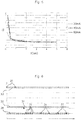
- the figure 5 represents an example of the quantity of reflected electromagnetic radiation energy captured by a receiver 26 such as those included in electronic components manufactured by VISHAY under the reference VCNL3020 or VCNL4010 or else that produced by STMicroelectronics under the reference VL6180X according to the distance between the receiver 26 and the portion of the frame 22 for different intensities (20mA, 40mA and 60mA) of the electric current supplied to the transmitter 24.
- the variation in the amount of energy of the reflected electromagnetic radiation is greater between 0.2cm and 1 cm in distance between the emitter 24 and the reflecting portion of the frame 22.
- the processing unit of the sensor 23 makes it possible to detect a displacement of the opening leaf on which the sensor 23 is placed relative to the frame 22 from reflection data supplied by the receiver 26 or produced by this processing unit from the instantaneous reflection signals delivered by the receiver 26.
- the processing unit of the sensor 23 makes it possible to detect a movement of the opening from a reference position of the opening.
- the processing unit is programmed to compare the reflection data with reference data which may be reference data of predetermined value or data representative of the reflection signals when the opening is in a reference position relative to the frame 22.
- the processing unit compares the reflection data with the reference data as soon as the processing unit of the home automation device receives a command to monitor the opening.
- This monitoring order can be transmitted to the processing unit by the user or else by means of detecting the presence of the user in the enclosed space to be protected.
- These user presence detection means may for example be an RFID identification circuit by radio frequency and an RFID reader.
- These presence detection means can be placed in the enclosed space to be protected or outside this enclosed space. In particular, these presence detection means can be placed on the frame 22 near the opening 21 or on the opening 21.
- Reference data can be generated during a calibration step and saved in a memory of the sensor 23. They can be adjusted during use of the device according to the invention, either on manual command d 'a user, either automatically according to a self-adaptation protocol. For example, an average value of the amount of energy of the reflected electromagnetic radiation measured on a plurality of successive measurements without detection of movement of the opening element can be used as a reference value.
- the processing unit After comparing the reflection data with the reference data, the processing unit is programmed to generate at least one signal, called the displacement signal, as a function of the result of the comparison between the reflection data.
- Such a displacement signal can be a displacement signal, called a positive displacement signal, representative of a return of a monitored leaf to a reference position.
- the displacement signal is produced when said comparison indicates that the instantaneous reflection signals or the reflection data take on a value which corresponds to a reference value corresponding to the fact that the leaf being monitored is in the reference position.
- the processing unit can thus be programmed to generate a positive displacement signal when at least one absolute value of the difference between the reflection data and the reference data supplied by the receiver 26 when the monitored leaf is in a position of reference, is less than a predetermined threshold value.
- This predetermined threshold value can be a percentage of said reference data.
- a positive displacement signal is produced when
- k is less than 25%, more particularly less than 20%, more particularly less than 15%, more particularly less than 10%, in particular of the order of 5%.
- a displacement signal can be a displacement signal, known as a negative displacement signal, representative of the fact that a monitored opening leaf has left a reference position.
- the displacement signal contains information on the distance between the leaf and the frame.
- the processing unit then generates a movement signal of the monitored opening element when the processing unit detects a value of the instantaneous reflection signals or of reflection data lower than a predetermined reference value representative of the fact that the receiver 26 no longer detects reflected electromagnetic radiation.
- the processing unit can generate a signal for displacement of the opening element when it detects a variation in the amount 31 of energy of the reflected electromagnetic radiation picked up by the receiver 26 for a current position of the opening relative to the amount of energy of the reflected electromagnetic radiation picked up by the receiver 26 when the opening is placed in a reference position, such as a closed position.
- the processing unit can thus be programmed to generate a displacement signal when at least one absolute value of the difference between the reflection data and reference data supplied by the receiver 26 when the leaf being monitored is in a position of reference, exceeds a predetermined threshold value.
- This predetermined threshold value can be a percentage of said reference data.
- a displacement signal is produced when IR-SI / R> k, where S is an instantaneous value of the reflection data, R is a value of the reference data and k is a predetermined ratio between 0% and 100% .
- k is greater than 5%, more particularly greater than 10%, more particularly greater than 15%, more particularly greater than 20%, in particular of the order of 25%.
- the processing unit can be programmed to generate a displacement signal when the reflection data becomes greater or less than a predetermined threshold value 32, which can be a lower threshold or an upper threshold, depending on the position of reference to be monitored and the location of the sensor relative to the opening.
- a predetermined threshold value 32 which can be a lower threshold or an upper threshold, depending on the position of reference to be monitored and the location of the sensor relative to the opening.
- the sensor 23 also advantageously comprises at least one accelerometer suitable for supplying signals representative of an acceleration of the leaf being monitored with respect to the frame 22.
- An accelerometer can be placed on the leaf 21 or else on the frame 22 near or on the frame framing the sash.
- Such an accelerometer can be used to detect shocks, in particular vibrations, on the sash when it is fixed to the sash or on the frame when it is attached to the frame. In particular, these shocks can occur during the opening, closing of the opening, or when the opening is handled suddenly.
- the vibrations linked to shocks can propagate on the frame as well as on the opening.
- the accelerometer also makes it possible to detect a displacement of the opening element in particular when it is placed on the opening element.
- Such an accelerometer notably makes it possible to confirm a displacement signal emitted by the processing unit from the reflection data. It can also make it possible to detect any movement of the opening, even though the reflection data would not allow such detection. It can also make it possible to increase the measurement frequency of the instantaneous reflection signals and / or the frequency of comparison between the reflection data and the reference data by the processing unit. However, such an accelerometer alone is not sufficient, for example to detect a slow opening of the opening.
- the sensor 23 can also include a magnetometer adapted to supply representative signals. of an orientation of the opening relative to the frame 22.
- the magnetometer can be used to detect a change of orientation of a swinging opening.
- the displacement signal can alternatively be used to confirm the opening acceleration information or the opening orientation information provided by the magnetometer.
- the senor 23 also comprises means for wireless communication of the displacement signals to a central processing unit.
- the wireless communication means can be adapted to transmit displacement signals by radio, sound, ultrasonic or optical waves.
- These wireless communication means can for example be chosen from Wi-Fi® antennas or Bluetooth® antennas.
- a central processing unit can communicate with a plurality of sensors 23.
- the central processing unit can also communicate remotely with an Internet server.
- the sensor 23 can include a man-machine interface allowing the user to interact with the sensor 23.
- this man-machine interface can be chosen from the group consisting of buttons and a touch screen, so to allow the user to start a calibration step.
- a home automation monitoring method may include a calibration step.
- This step consists in measuring the quantity of energy of the reflected electromagnetic radiation captured by the receiver 26 when the opening is in a reference position, in particular a closed or ajar position.
- This calibration step can be started automatically or manually.
- the user can start the calibration step by interacting with the human-machine interface of the sensor.
- the processing unit can also be adapted to start a calibration step automatically when the home automation device 20 and in particular the processing unit are powered up.
- the user positions the opening in a desired reference position so that the sensor 23 can measure the amount of energy of the reflected electromagnetic radiation picked up by the receiver 26 in order to develop reference data from the reflection signals picked up by the receiver 26.
- the processing unit of the sensor 23 is advantageously adapted to adjust the power of the electromagnetic radiation emitted by the transmitter 24 as a function of the amount of energy of the reflected electromagnetic radiation captured by the receiver 26.
- the power of the electromagnetic radiation emitted is increased by increasing the intensity of the electric current supplying the transmitter 24 so as to increase the electric power supplying the transmitter 24.
- the processing unit is also adapted to minimize the power of the electromagnetic radiation emitted by the transmitter 24 to reduce the consumption of electrical energy from the sensor and increase the autonomy of the electrical supply.
- the portion of the frame 22 reflecting the emitted electromagnetic radiation is chosen so as not to produce a specular reflection of this emitted electromagnetic radiation, but only a backscattering or a partial reflection. In this way, any attempt to neutralize the device according to the invention which consists in placing a perfectly reflecting surface opposite the sensor is prevented. In fact, too much energy from the reflected electromagnetic radiation, in particular greater than that corresponding to the reference position of the monitored window, can be used by the processing unit to emit an alarm signal.
- Starting the calibration step may require user authentication.
- the reference data produced during this calibration step are then recorded in the memory of the sensor 23.
- the processing unit of the sensor 23 wakes up the transmitter 24 and the receiver 26 periodically in order to carry out measurements of the amount 31 of energy of the electromagnetic radiation reflected as that represented in the figure 6 . These measurements can be performed for example every three seconds. However, nothing prevents having a duration between each measurement of less than or more than three seconds. Between each measurement, the processing unit is adapted to stop the electrical supply to the transmitter 24 and the receiver 26 in order to increase the autonomy of the electrical supply.
- the processing unit is adapted to increase the frequency of the measurements of the amount of energy of the electromagnetic radiation reflected when signals supplied by an accelerometer representative of an acceleration of the opening are greater than a threshold.
- said acceleration threshold can be representative of an acceleration between 0.15 m / s 2 and 5 m / s 2 .
- the processing unit then generates reflection data from instantaneous reflection signals delivered by the receiver 26 and then compares the reflection data with the reference data recorded in the memory of the sensor 23.
- the opening of the door causes a reduction in the value of the data reflection.
- the electromagnetic radiation emitted by the emitter 24, moving away from the frame 22 during the opening of the opening is no longer directed towards the portion of the frame 22 towards which these emitted electromagnetic radiation is directed when the the sash is in the reference position.
- the amount of energy of the reflected electromagnetic radiation captured by the receiver 26 therefore decreases with during the opening of the opening.
- the angle of reflection varies so that the receiver 26 picks up a quantity of energy of the reflected electromagnetic radiation less than that which it picks up when the opening leaf is in the reference position.
- the processing unit compares the value of the reflection data with a reference value as indicated above.
- the processing unit compares the reflection data with a ceiling, called the displacement ceiling, calculated by the processing unit as a function of the reference data representative of the reflection signals when the leaf is in a reference position relative to the frame 22 and of the reference data representative of the reflection signals when the leaf is in an open position and therefore of the quantity 36 of energy of the reflected electromagnetic radiation picked up by the receiver 26 when the opening is in an open position.
- the processing unit emits a displacement signal indicating that the leaf has been moved to an open position.
- a method and a device according to the invention make it possible to detect a displacement - in particular an opening -, or an absence of displacement, of an opening monitored by a distance which can be of the order of 1 cm.
- the displacement signal can be emitted after a confirmation step during which the processing unit verifies that several measurements, successive in time, of the amount of energy of the electromagnetic radiation reflected exceed the displacement threshold or ceiling.
- the frequency of the measurements can be increased by the processing unit from the first measurement of an amount of energy of the reflected electromagnetic radiation exceeding the threshold or the ceiling. of displacement. Increasing the frequency of measurements makes it possible to trigger a movement signal more quickly.
- the displacement signal is transmitted by means of the wireless communication means of the home automation device to the central processing unit adapted to trigger an alarm and to warn the user of an intrusion.
- the central processing unit adapted to trigger an alarm and to warn the user of an intrusion.
- the displacement signal is produced when the signals supplied by the accelerometer, representative of an acceleration of the opening being monitored, are greater than a threshold, called the acceleration detection threshold.
- a threshold called the acceleration detection threshold.
- an alarm can be triggered.
- a detection threshold may be representative of an acceleration of the order of 1 m / s 2 .
- the reflection data are compared with data representative of the orientation of the opening relative to the frame 22 provided by the magnetometer carried by the opening so as to confirm that a movement of the opening has product.
- Such a comparison makes it possible to validate the detection of a movement of the opening element before transmitting a displacement signal and consequently to reduce the risk of triggering a false alarm.
- the invention therefore relates to a home automation device 20 for monitoring an opening with respect to a frame 22.
- the invention also relates to a home automation method for monitoring an opening with respect to a frame 22.
- the home automation device 20 can comprise, in combination with the transmitter 24 and the receiver 26, only a magnetometer or only a accelerometer or a magnetometer and an accelerometer.
- a home automation device according to the invention may comprise a plurality of openings, each opening may include a plurality of sensors 23.
- the sensor may be integrated into the opening or the frame, in particular in a bore of a song of the sash or the frame (in particular in the edge of the frame framing the sash).
- the invention can therefore be applied to detect an intrusion into an enclosed space to be protected such as a house, an industrial building or a shop.
Claims (13)
- Verfahren zur Überwachung mindestens einer Platte, genannt überwachter Flügel (21), welche bezogen auf eine Zarge (22) derart angebracht ist, dass sie relativ zu der Zarge beweglich ist, dadurch gekennzeichnet, dass:- mindestens ein Sender (24) auf einer Vorderseite eines ersten Elements, das entweder die Zarge (22) oder ein überwachter Flügel (21) ist, hervorstehend befestigt ist, wobei jeder Sender derart ausgewählt und angeordnet ist, dass er eine Strahlung, die entweder eine elektromagnetische Strahlung oder eine akustische Strahlung ist, in Richtung eines zweiten Elements emittiert,• welches sich von dem ersten Element unterscheidet,• welches entweder die Zarge oder ein überwachter Flügel ist, derart, dass die emittierte Strahlung zumindest teilweise durch das zweite Element reflektiert wird,- mindestens ein Empfänger (26) derart ausgewählt und angeordnet ist,• dass eine Strahlung, genannt reflektierte Strahlung, erfasst wird, welche von mindestens einem an einem ersten Element befestigten Sender ausgeht und durch ein zweites Element reflektiert wird,• und dass Signale, genannt Reflexionssignale, geliefert werden, die für mindestens eine Eigenschaft der reflektierten Strahlung repräsentativ sind,- wobei jeder Sender, jeder Empfänger, jedes erste Element, jedes zweite Element derart ausgewählt und angeordnet ist, dass mindestens ein Teil der Reflexionssignale verändert wird, wenn mindestens ein überwachter Flügel zumindest ausgehend von mindestens einer vorbestimmten Referenzposition des überwachten Flügels bewegt wird,- die durch jeden Empfänger gelieferten Reflexionssignale, genannt momentane Reflexionssignale, zu jedem Zeitpunkt mit mindestens einem Wert, genannt Referenzwert, verglichen werden,- mindestens ein Signal, genannt Bewegungssignal, welches für eine Bewegung mindestens eines überwachten Flügels relativ zu einer Referenzposition repräsentativ ist, in Abhängigkeit von dem Ergebnis des Vergleichs zwischen den momentanen Reflexionssignalen und jedem Referenzwert erzeugt wird,wobei der mindestens eine Empfänger (26) auf einer Vorderseite eines dritten Elements, das entweder die Zarge oder ein Flügel ist, hervorstehend befestigt ist, derart, dass die durch den Sender (24) emittierte Strahlung eine Emissionsachse (28) aufweist, welche einen Winkel α bildet, der bezogen auf die Vorderseite des ersten Elements größer als 5° und kleiner als 90° ist, und derart, dass:- die Emissionsachse (28) der emittierten Strahlung in Richtung des zweiten Elements ausgerichtet ist,- die emittierte Strahlung durch das zweite Element in Richtung des Empfängers (26) reflektiert wird.
- Verfahren nach Anspruch 1, dadurch gekennzeichnet, dass mindestens ein Empfänger (26) auf dem ersten Element befestigt ist, auf welchem mindestens ein Sender (24) befestigt ist, wobei der Empfänger (26) zum Empfangen einer von mindestens einem auf dem ersten Element befestigten derartigen Sender (24) ausgehenden reflektierten Strahlung ausgebildet ist.
- Verfahren nach einem der Ansprüche 1 oder 2, dadurch gekennzeichnet, dass jeder Empfänger (26) derart ausgewählt ist, dass er in der Lage ist, momentane Reflexionssignale zu liefern, welche für eine Energiemenge der durch den Empfänger (26) erfassten reflektierten Strahlung repräsentativ sind.
- Verfahren nach einem der Ansprüche 1 bis 3, dadurch gekennzeichnet, dass mindestens ein Sender und mindestens ein Empfänger derart ausgewählt und angeordnet sind, dass die durch den Empfänger gelieferten momentanen Reflexionssignale zumindest im Wesentlichen einem vorgegebenen Wert entsprechen, wenn jeder überwachte Flügel, dessen Bewegung die durch den Empfänger gelieferten Reflexionssignale verändert, ausgehend von einer Referenzposition des überwachten Flügels um eine Distanz bewegt wird, welche größer ist als eine Distanz, genannt Mindestbewegungsdistanz, welche kleiner ist als 5 cm.
- Verfahren nach einem der Ansprüche 1 bis 4, dadurch gekennzeichnet, dass mindestens ein Sender und mindestens ein Empfänger und das zweite Element derart ausgewählt und angeordnet sind, dass die durch das zweite Element reflektierte Strahlung vom Empfänger nur dann erfassbar ist, wenn das zweite Element weniger als 10 cm von dem Empfänger entfernt platziert ist.
- Vorrichtung (20) zur Überwachung mindestens einer Platte, genannt überwachter Flügel (21), welche bezogen auf eine Zarge (22) derart angebracht ist, dass sie relativ zu der Zarge beweglich ist, dadurch gekennzeichnet, dass die Vorrichtung Folgendes umfasst:- mindestens einen Sender (24), der auf einer Vorderseite eines ersten Elements, das entweder die Zarge oder ein überwachter Flügel (21) ist, hervorstehend befestigbar ist, wobei jeder Sender dazu ausgebildet ist, eine Strahlung, die entweder eine elektromagnetische Strahlung oder eine akustische Strahlung ist, in Richtung mindestens eines Teils von mindestens einem zweiten Element zu emittieren,• welches sich von dem ersten Element unterscheidet,• welches entweder die Zarge oder ein überwachter Flügel ist, derart, dass die emittierte Strahlung zumindest teilweise durch das zweite Element reflektierbar ist,- mindestens einen Empfänger (26), der derart ausgebildet und angeordnet ist,• dass er eine Strahlung, genannt reflektierte Strahlung, erfasst, welche von mindestens einem an einem ersten Element befestigten Sender ausgeht und durch mindestens ein zweites Element reflektiert wird,• und dass er Signale, genannt Reflexionssignale, liefert, welche für mindestens eine Eigenschaft der reflektierten Strahlung repräsentativ sind,- wobei jeder Sender, jeder Empfänger, jedes erste Element, jedes zweite Element derart auswählbar und anordenbar ist, dass mindestens ein Teil der Reflexionssignale veränderbar ist, wenn mindestens ein überwachter Flügel zumindest ausgehend von mindestens einer vorbestimmten Referenzposition des überwachten Flügels bewegt wird,- eine Reflexionssignal-Verarbeitungseinheit, die dazu ausgebildet ist,wobei der mindestens eine Empfänger (26) auf einer Vorderseite eines dritten Elements, das entweder die Zarge oder ein Flügel ist, hervorstehend befestigt ist, derart, dass die durch den Sender (24) emittierte Strahlung eine Emissionsachse (28)aufweist, welche einen Winkel α bildet, der bezogen auf die Vorderseite des ersten Elements größer als 5° und kleiner als 90° ist, und derart, dass• die durch jeden Empfänger gelieferten Reflexionssignale, genannt momentane Reflexionssignale, zu jedem Zeitpunkt mit mindestens einem Wert, genannt Referenzwert, zu vergleichen,• mindestens ein Signal, genannt Bewegungssignal, welches für eine Bewegung mindestens eines überwachten Flügels relativ zu einer Referenzposition repräsentativ ist, in Abhängigkeit von dem Ergebnis des Vergleichs zwischen den momentanen Reflexionssignalen und jedem Referenzwert zu erzeugen,- die Emissionsachse (28) der emittierten Strahlung in Richtung des zweiten Elements ausgerichtet ist,- die emittierte Strahlung durch das zweite Element in Richtung des Empfängers (26) reflektierbar ist.
- Vorrichtung nach Anspruch 6, dadurch gekennzeichnet, dass die Vorrichtung mindestens einen Empfänger (26) umfasst, der auf dem ersten Element befestigt ist, auf welchem mindestens ein Sender (24) befestigt ist, wobei der Empfänger zum Empfangen einer von mindestens einem auf dem ersten Element befestigten derartigen Sender ausgehenden reflektierten Strahlung ausgebildet ist.
- Vorrichtung nach einem der Ansprüche 6 oder 7, dadurch gekennzeichnet, dass jeder Empfänger (26) derart ausgebildet ist, dass er in der Lage ist, momentane Reflexionssignale, die für eine Energiemenge der durch den Empfänger (26) erfassten reflektierten Strahlung repräsentativ sind, zu liefern.
- Vorrichtung nach einem der Ansprüche 7 oder 8, dadurch gekennzeichnet, dass die Vorrichtung ein Gehäuse (37) umfasst, welches eine Wand umfasst, die einen abgeschlossenen Bereich des Gehäuses begrenzt, in welchem mindestens ein Sender (24) und mindestens ein Empfänger (26) platziert sind, wobei die Wand mindestens ein Fenster, einschließlich einer Öffnung, aufweist, welches für die emittierte elektromagnetische Strahlung durchlässig ist und den Durchtritt der aus dem abgeschlossenen Bereich des Gehäuses heraus emittierten elektromagnetischen Strahlung ermöglicht, und mindestens ein Fenster, einschließlich einer Öffnung, aufweist, welches für die reflektierte elektromagnetische Strahlung durchlässig ist und den Durchtritt der von außerhalb des abgeschlossenen Bereichs des Gehäuses in Richtung des Inneren des abgeschlossenen Bereichs des Gehäuses reflektierten elektromagnetischen Strahlung ermöglicht.
- Vorrichtung nach einem der Ansprüche 6 bis 9, dadurch gekennzeichnet, dass die Vorrichtung des Weiteren mindestens einen an einem Element, das entweder die Zarge (22) oder ein überwachter Flügel (21) ist, befestigten Beschleunigungsmesser umfasst, wobei der Beschleunigungsmesser dazu ausgebildet ist, Signale zu liefern, die für eine Beschleunigung mindestens eines überwachten Flügels (21) bezogen auf eine Zarge (22) repräsentativ sind.
- Vorrichtung nach einem der Ansprüche 6 bis 10, dadurch gekennzeichnet, dass die Vorrichtung des Weiteren mindestens ein an einem überwachten Flügel (21) befestigtes und zum Liefern von Signalen, die für eine Ausrichtung des überwachten Flügels (21) bezogen auf die Zarge (21) repräsentativ sind, ausgebildetes Magnetometer umfasst.
- Vorrichtung nach einem der Ansprüche 6 bis 11, dadurch gekennzeichnet, dass die Vorrichtung zur Überwachung mindestens eine Stromversorgung umfasst.
- Öffnung, umfassend eine Zarge und mindestens einen Flügel, der bezogen auf eine Zarge (22) derart angebracht ist, dass er relativ zu der Zarge beweglich ist, und eine Vorrichtung zur Überwachung mindestens eines Flügels, genannt überwachter Flügel (21), dadurch gekennzeichnet, dass die Öffnung mindestens eine Vorrichtung zur Überwachung nach einem der Ansprüche 6 bis 12 umfasst.
Priority Applications (1)
| Application Number | Priority Date | Filing Date | Title |
|---|---|---|---|
| PL18164380T PL3383058T3 (pl) | 2017-03-28 | 2018-03-27 | Sposób i urządzenie do monitorowania co najmniej jednego skrzydła względem ościeżnicy |
Applications Claiming Priority (1)
| Application Number | Priority Date | Filing Date | Title |
|---|---|---|---|
| FR1752595A FR3064799B1 (fr) | 2017-03-28 | 2017-03-28 | Procede et dispositif de surveillance d'au moins un ouvrant par rapport a un dormant |
Publications (2)
| Publication Number | Publication Date |
|---|---|
| EP3383058A1 EP3383058A1 (de) | 2018-10-03 |
| EP3383058B1 true EP3383058B1 (de) | 2020-05-27 |
Family
ID=59253670
Family Applications (1)
| Application Number | Title | Priority Date | Filing Date |
|---|---|---|---|
| EP18164380.0A Active EP3383058B1 (de) | 2017-03-28 | 2018-03-27 | Verfahren und vorrichtung zur überwachung des öffnungszustand zwischen eines flügels und einer zarge |
Country Status (3)
| Country | Link |
|---|---|
| EP (1) | EP3383058B1 (de) |
| FR (1) | FR3064799B1 (de) |
| PL (1) | PL3383058T3 (de) |
Families Citing this family (1)
| Publication number | Priority date | Publication date | Assignee | Title |
|---|---|---|---|---|
| FR3099012B1 (fr) * | 2019-07-17 | 2022-06-24 | Somfy Activites Sa | Méthodes et dispositifs pour l’émission d’un message radio |
Family Cites Families (1)
| Publication number | Priority date | Publication date | Assignee | Title |
|---|---|---|---|---|
| US8773263B2 (en) * | 2011-09-01 | 2014-07-08 | Ecolink Intelligent Technology, Inc. | Security apparatus and method |
-
2017
- 2017-03-28 FR FR1752595A patent/FR3064799B1/fr active Active
-
2018
- 2018-03-27 EP EP18164380.0A patent/EP3383058B1/de active Active
- 2018-03-27 PL PL18164380T patent/PL3383058T3/pl unknown
Non-Patent Citations (1)
| Title |
|---|
| None * |
Also Published As
| Publication number | Publication date |
|---|---|
| PL3383058T3 (pl) | 2020-11-30 |
| EP3383058A1 (de) | 2018-10-03 |
| FR3064799B1 (fr) | 2020-10-09 |
| FR3064799A1 (fr) | 2018-10-05 |
Similar Documents
| Publication | Publication Date | Title |
|---|---|---|
| EP2350984B1 (de) | Einrichtung zum automatischen entriegeln eines öffnungsfähigen panels eines kraftfahrzeugs | |
| EP2350983B1 (de) | Einrichtung zum automatischen entriegeln eines öffnungsfähigen panels eines kraftfahrzeugs | |
| EP3022719B1 (de) | Heimautomatisierungsvorrichtung zur überwachung der bewegung eines schwingenden flügels und verfahren zur erhöhung der zuverlässigkeit solch einer vorrichtung | |
| FR3052902B1 (fr) | Capteur d'alarme, systeme comprenant un tel capteur, et procede d'utilisation de ce systeme d'alarme | |
| EP2807638A1 (de) | System zur erkennung eines eindringversuches in einen durch einen zaun definierten perimeter | |
| EP3383058B1 (de) | Verfahren und vorrichtung zur überwachung des öffnungszustand zwischen eines flügels und einer zarge | |
| EP3629307A1 (de) | Personenzählvorrichtung und -verfahren | |
| EP3428890A1 (de) | Verfahren und vorrichtung zur türüberwachung, und überwachungssystem, das eine solche vorrichtung einschliesst | |
| EP3158343B1 (de) | Energieeffiziente domotikvorrichtung und verfahren zur verfolgung der bewegung eines zu überwachenden objekts | |
| EP3662457B1 (de) | Alarmvorrichtung mit unterscheidung zwischen rechtmässigem bewohner und eindringling | |
| FR3054510A1 (fr) | Procede de defense contre une action de relais attaque sur une activation a distance d'une fonction presente dans un vehicule automobile | |
| EP3649627B1 (de) | Verfahren und vorrichtung zur detektion des eindringens | |
| WO2002011096A1 (fr) | Procede et dispositif pour la protection en continu contre les intrusions dans des locaux eventuellement habites | |
| FR2892549A1 (fr) | Systeme d'alarme, unite centrale de systeme d'alarme et procede de protection d'une telle unite centrale | |
| EP3173565B1 (de) | Betriebssteuerungsverfahren einer hausanlage zum verschliessen | |
| EP3528224B1 (de) | Vorrichtung und verfahren zur präsenz- und/oder bewegungserkennung durch infrarot-messung | |
| WO2022101595A1 (fr) | Ensemble de serrure électronique | |
| EP3314592B1 (de) | Heimautomatisierungsvorrichtung, verfahren zur steuerung einer heimautomatisierungsvorrichtung und computerprogramm | |
| FR3126804A1 (fr) | Dispositif de détermination adaptative d’actions sur un objet par analyse progressive des contraintes qu’elles génèrent | |
| EP3819447A1 (de) | Elektromechanische vorrichtung zur betätigung der verriegelung mit doppelten abstandssensoren, und verfahren | |
| WO2015114170A1 (fr) | Dispositif de détection d'incendie ou de fuite de gaz et système de sécurisation d'un local le comportant | |
| FR3039307A1 (fr) | Systeme de detection de fumee |
Legal Events
| Date | Code | Title | Description |
|---|---|---|---|
| PUAI | Public reference made under article 153(3) epc to a published international application that has entered the european phase |
Free format text: ORIGINAL CODE: 0009012 |
|
| STAA | Information on the status of an ep patent application or granted ep patent |
Free format text: STATUS: THE APPLICATION HAS BEEN PUBLISHED |
|
| AK | Designated contracting states |
Kind code of ref document: A1 Designated state(s): AL AT BE BG CH CY CZ DE DK EE ES FI FR GB GR HR HU IE IS IT LI LT LU LV MC MK MT NL NO PL PT RO RS SE SI SK SM TR |
|
| AX | Request for extension of the european patent |
Extension state: BA ME |
|
| STAA | Information on the status of an ep patent application or granted ep patent |
Free format text: STATUS: REQUEST FOR EXAMINATION WAS MADE |
|
| 17P | Request for examination filed |
Effective date: 20190305 |
|
| RBV | Designated contracting states (corrected) |
Designated state(s): AL AT BE BG CH CY CZ DE DK EE ES FI FR GB GR HR HU IE IS IT LI LT LU LV MC MK MT NL NO PL PT RO RS SE SI SK SM TR |
|
| GRAP | Despatch of communication of intention to grant a patent |
Free format text: ORIGINAL CODE: EPIDOSNIGR1 |
|
| STAA | Information on the status of an ep patent application or granted ep patent |
Free format text: STATUS: GRANT OF PATENT IS INTENDED |
|
| RIC1 | Information provided on ipc code assigned before grant |
Ipc: G08B 13/08 20060101ALI20191205BHEP Ipc: G08B 13/14 20060101ALI20191205BHEP Ipc: H04Q 9/00 20060101AFI20191205BHEP |
|
| INTG | Intention to grant announced |
Effective date: 20200108 |
|
| GRAS | Grant fee paid |
Free format text: ORIGINAL CODE: EPIDOSNIGR3 |
|
| GRAA | (expected) grant |
Free format text: ORIGINAL CODE: 0009210 |
|
| STAA | Information on the status of an ep patent application or granted ep patent |
Free format text: STATUS: THE PATENT HAS BEEN GRANTED |
|
| AK | Designated contracting states |
Kind code of ref document: B1 Designated state(s): AL AT BE BG CH CY CZ DE DK EE ES FI FR GB GR HR HU IE IS IT LI LT LU LV MC MK MT NL NO PL PT RO RS SE SI SK SM TR |
|
| REG | Reference to a national code |
Ref country code: GB Ref legal event code: FG4D Free format text: NOT ENGLISH |
|
| REG | Reference to a national code |
Ref country code: CH Ref legal event code: EP |
|
| REG | Reference to a national code |
Ref country code: AT Ref legal event code: REF Ref document number: 1275826 Country of ref document: AT Kind code of ref document: T Effective date: 20200615 |
|
| REG | Reference to a national code |
Ref country code: DE Ref legal event code: R096 Ref document number: 602018004813 Country of ref document: DE |
|
| REG | Reference to a national code |
Ref country code: LT Ref legal event code: MG4D |
|
| PG25 | Lapsed in a contracting state [announced via postgrant information from national office to epo] |
Ref country code: FI Free format text: LAPSE BECAUSE OF FAILURE TO SUBMIT A TRANSLATION OF THE DESCRIPTION OR TO PAY THE FEE WITHIN THE PRESCRIBED TIME-LIMIT Effective date: 20200527 Ref country code: NO Free format text: LAPSE BECAUSE OF FAILURE TO SUBMIT A TRANSLATION OF THE DESCRIPTION OR TO PAY THE FEE WITHIN THE PRESCRIBED TIME-LIMIT Effective date: 20200827 Ref country code: GR Free format text: LAPSE BECAUSE OF FAILURE TO SUBMIT A TRANSLATION OF THE DESCRIPTION OR TO PAY THE FEE WITHIN THE PRESCRIBED TIME-LIMIT Effective date: 20200828 Ref country code: PT Free format text: LAPSE BECAUSE OF FAILURE TO SUBMIT A TRANSLATION OF THE DESCRIPTION OR TO PAY THE FEE WITHIN THE PRESCRIBED TIME-LIMIT Effective date: 20200928 Ref country code: LT Free format text: LAPSE BECAUSE OF FAILURE TO SUBMIT A TRANSLATION OF THE DESCRIPTION OR TO PAY THE FEE WITHIN THE PRESCRIBED TIME-LIMIT Effective date: 20200527 Ref country code: SE Free format text: LAPSE BECAUSE OF FAILURE TO SUBMIT A TRANSLATION OF THE DESCRIPTION OR TO PAY THE FEE WITHIN THE PRESCRIBED TIME-LIMIT Effective date: 20200527 Ref country code: IS Free format text: LAPSE BECAUSE OF FAILURE TO SUBMIT A TRANSLATION OF THE DESCRIPTION OR TO PAY THE FEE WITHIN THE PRESCRIBED TIME-LIMIT Effective date: 20200927 |
|
| REG | Reference to a national code |
Ref country code: NL Ref legal event code: MP Effective date: 20200527 |
|
| PG25 | Lapsed in a contracting state [announced via postgrant information from national office to epo] |
Ref country code: HR Free format text: LAPSE BECAUSE OF FAILURE TO SUBMIT A TRANSLATION OF THE DESCRIPTION OR TO PAY THE FEE WITHIN THE PRESCRIBED TIME-LIMIT Effective date: 20200527 Ref country code: BG Free format text: LAPSE BECAUSE OF FAILURE TO SUBMIT A TRANSLATION OF THE DESCRIPTION OR TO PAY THE FEE WITHIN THE PRESCRIBED TIME-LIMIT Effective date: 20200827 Ref country code: LV Free format text: LAPSE BECAUSE OF FAILURE TO SUBMIT A TRANSLATION OF THE DESCRIPTION OR TO PAY THE FEE WITHIN THE PRESCRIBED TIME-LIMIT Effective date: 20200527 Ref country code: RS Free format text: LAPSE BECAUSE OF FAILURE TO SUBMIT A TRANSLATION OF THE DESCRIPTION OR TO PAY THE FEE WITHIN THE PRESCRIBED TIME-LIMIT Effective date: 20200527 |
|
| REG | Reference to a national code |
Ref country code: AT Ref legal event code: MK05 Ref document number: 1275826 Country of ref document: AT Kind code of ref document: T Effective date: 20200527 |
|
| PG25 | Lapsed in a contracting state [announced via postgrant information from national office to epo] |
Ref country code: AL Free format text: LAPSE BECAUSE OF FAILURE TO SUBMIT A TRANSLATION OF THE DESCRIPTION OR TO PAY THE FEE WITHIN THE PRESCRIBED TIME-LIMIT Effective date: 20200527 Ref country code: NL Free format text: LAPSE BECAUSE OF FAILURE TO SUBMIT A TRANSLATION OF THE DESCRIPTION OR TO PAY THE FEE WITHIN THE PRESCRIBED TIME-LIMIT Effective date: 20200527 |
|
| PG25 | Lapsed in a contracting state [announced via postgrant information from national office to epo] |
Ref country code: ES Free format text: LAPSE BECAUSE OF FAILURE TO SUBMIT A TRANSLATION OF THE DESCRIPTION OR TO PAY THE FEE WITHIN THE PRESCRIBED TIME-LIMIT Effective date: 20200527 Ref country code: AT Free format text: LAPSE BECAUSE OF FAILURE TO SUBMIT A TRANSLATION OF THE DESCRIPTION OR TO PAY THE FEE WITHIN THE PRESCRIBED TIME-LIMIT Effective date: 20200527 Ref country code: CZ Free format text: LAPSE BECAUSE OF FAILURE TO SUBMIT A TRANSLATION OF THE DESCRIPTION OR TO PAY THE FEE WITHIN THE PRESCRIBED TIME-LIMIT Effective date: 20200527 Ref country code: RO Free format text: LAPSE BECAUSE OF FAILURE TO SUBMIT A TRANSLATION OF THE DESCRIPTION OR TO PAY THE FEE WITHIN THE PRESCRIBED TIME-LIMIT Effective date: 20200527 Ref country code: SM Free format text: LAPSE BECAUSE OF FAILURE TO SUBMIT A TRANSLATION OF THE DESCRIPTION OR TO PAY THE FEE WITHIN THE PRESCRIBED TIME-LIMIT Effective date: 20200527 Ref country code: IT Free format text: LAPSE BECAUSE OF FAILURE TO SUBMIT A TRANSLATION OF THE DESCRIPTION OR TO PAY THE FEE WITHIN THE PRESCRIBED TIME-LIMIT Effective date: 20200527 Ref country code: EE Free format text: LAPSE BECAUSE OF FAILURE TO SUBMIT A TRANSLATION OF THE DESCRIPTION OR TO PAY THE FEE WITHIN THE PRESCRIBED TIME-LIMIT Effective date: 20200527 Ref country code: DK Free format text: LAPSE BECAUSE OF FAILURE TO SUBMIT A TRANSLATION OF THE DESCRIPTION OR TO PAY THE FEE WITHIN THE PRESCRIBED TIME-LIMIT Effective date: 20200527 |
|
| PG25 | Lapsed in a contracting state [announced via postgrant information from national office to epo] |
Ref country code: SK Free format text: LAPSE BECAUSE OF FAILURE TO SUBMIT A TRANSLATION OF THE DESCRIPTION OR TO PAY THE FEE WITHIN THE PRESCRIBED TIME-LIMIT Effective date: 20200527 |
|
| REG | Reference to a national code |
Ref country code: DE Ref legal event code: R097 Ref document number: 602018004813 Country of ref document: DE |
|
| PLBE | No opposition filed within time limit |
Free format text: ORIGINAL CODE: 0009261 |
|
| STAA | Information on the status of an ep patent application or granted ep patent |
Free format text: STATUS: NO OPPOSITION FILED WITHIN TIME LIMIT |
|
| 26N | No opposition filed |
Effective date: 20210302 |
|
| PG25 | Lapsed in a contracting state [announced via postgrant information from national office to epo] |
Ref country code: SI Free format text: LAPSE BECAUSE OF FAILURE TO SUBMIT A TRANSLATION OF THE DESCRIPTION OR TO PAY THE FEE WITHIN THE PRESCRIBED TIME-LIMIT Effective date: 20200527 |
|
| PG25 | Lapsed in a contracting state [announced via postgrant information from national office to epo] |
Ref country code: MC Free format text: LAPSE BECAUSE OF FAILURE TO SUBMIT A TRANSLATION OF THE DESCRIPTION OR TO PAY THE FEE WITHIN THE PRESCRIBED TIME-LIMIT Effective date: 20200527 |
|
| REG | Reference to a national code |
Ref country code: CH Ref legal event code: PL |
|
| REG | Reference to a national code |
Ref country code: BE Ref legal event code: MM Effective date: 20210331 |
|
| PG25 | Lapsed in a contracting state [announced via postgrant information from national office to epo] |
Ref country code: IE Free format text: LAPSE BECAUSE OF NON-PAYMENT OF DUE FEES Effective date: 20210327 Ref country code: LU Free format text: LAPSE BECAUSE OF NON-PAYMENT OF DUE FEES Effective date: 20210327 Ref country code: LI Free format text: LAPSE BECAUSE OF NON-PAYMENT OF DUE FEES Effective date: 20210331 Ref country code: CH Free format text: LAPSE BECAUSE OF NON-PAYMENT OF DUE FEES Effective date: 20210331 |
|
| PG25 | Lapsed in a contracting state [announced via postgrant information from national office to epo] |
Ref country code: BE Free format text: LAPSE BECAUSE OF NON-PAYMENT OF DUE FEES Effective date: 20210331 |
|
| PGFP | Annual fee paid to national office [announced via postgrant information from national office to epo] |
Ref country code: FR Payment date: 20230209 Year of fee payment: 6 |
|
| PGFP | Annual fee paid to national office [announced via postgrant information from national office to epo] |
Ref country code: PL Payment date: 20230222 Year of fee payment: 6 |
|
| PG25 | Lapsed in a contracting state [announced via postgrant information from national office to epo] |
Ref country code: CY Free format text: LAPSE BECAUSE OF FAILURE TO SUBMIT A TRANSLATION OF THE DESCRIPTION OR TO PAY THE FEE WITHIN THE PRESCRIBED TIME-LIMIT Effective date: 20200527 |
|
| PG25 | Lapsed in a contracting state [announced via postgrant information from national office to epo] |
Ref country code: HU Free format text: LAPSE BECAUSE OF FAILURE TO SUBMIT A TRANSLATION OF THE DESCRIPTION OR TO PAY THE FEE WITHIN THE PRESCRIBED TIME-LIMIT; INVALID AB INITIO Effective date: 20180327 |
|
| PG25 | Lapsed in a contracting state [announced via postgrant information from national office to epo] |
Ref country code: MK Free format text: LAPSE BECAUSE OF FAILURE TO SUBMIT A TRANSLATION OF THE DESCRIPTION OR TO PAY THE FEE WITHIN THE PRESCRIBED TIME-LIMIT Effective date: 20200527 |
|
| PGFP | Annual fee paid to national office [announced via postgrant information from national office to epo] |
Ref country code: DE Payment date: 20240307 Year of fee payment: 7 Ref country code: GB Payment date: 20240325 Year of fee payment: 7 |