EP3382840B1 - Vorrichtung zur überwachung eines energiesystems und verfahren zur überwachung eines energiesystems - Google Patents
Vorrichtung zur überwachung eines energiesystems und verfahren zur überwachung eines energiesystems Download PDFInfo
- Publication number
- EP3382840B1 EP3382840B1 EP16868376.1A EP16868376A EP3382840B1 EP 3382840 B1 EP3382840 B1 EP 3382840B1 EP 16868376 A EP16868376 A EP 16868376A EP 3382840 B1 EP3382840 B1 EP 3382840B1
- Authority
- EP
- European Patent Office
- Prior art keywords
- dynamic behavior
- electric power
- power system
- estimation
- constant
- Prior art date
- Legal status (The legal status is an assumption and is not a legal conclusion. Google has not performed a legal analysis and makes no representation as to the accuracy of the status listed.)
- Active
Links
Images


Classifications
-
- G—PHYSICS
- G01—MEASURING; TESTING
- G01R—MEASURING ELECTRIC VARIABLES; MEASURING MAGNETIC VARIABLES
- G01R21/00—Arrangements for measuring electric power or power factor
- G01R21/133—Arrangements for measuring electric power or power factor by using digital technique
-
- H—ELECTRICITY
- H02—GENERATION; CONVERSION OR DISTRIBUTION OF ELECTRIC POWER
- H02J—ELECTRIC POWER NETWORKS; CIRCUIT ARRANGEMENTS OR SYSTEMS FOR SUPPLYING OR DISTRIBUTING ELECTRIC POWER; SYSTEMS FOR STORING ELECTRIC ENERGY
- H02J13/00—Circuit arrangements for providing remote monitoring or remote control of equipment in a power distribution network
- H02J13/12—Monitoring network conditions, e.g. electrical magnitudes or operational status
-
- H—ELECTRICITY
- H02—GENERATION; CONVERSION OR DISTRIBUTION OF ELECTRIC POWER
- H02J—ELECTRIC POWER NETWORKS; CIRCUIT ARRANGEMENTS OR SYSTEMS FOR SUPPLYING OR DISTRIBUTING ELECTRIC POWER; SYSTEMS FOR STORING ELECTRIC ENERGY
- H02J3/00—Circuit arrangements for AC mains or AC distribution networks
-
- G—PHYSICS
- G01—MEASURING; TESTING
- G01R—MEASURING ELECTRIC VARIABLES; MEASURING MAGNETIC VARIABLES
- G01R31/00—Arrangements for testing electric properties; Arrangements for locating electric faults; Arrangements for electrical testing characterised by what is being tested not provided for elsewhere
- G01R31/34—Testing dynamo-electric machines
- G01R31/343—Testing dynamo-electric machines in operation
-
- H—ELECTRICITY
- H02—GENERATION; CONVERSION OR DISTRIBUTION OF ELECTRIC POWER
- H02J—ELECTRIC POWER NETWORKS; CIRCUIT ARRANGEMENTS OR SYSTEMS FOR SUPPLYING OR DISTRIBUTING ELECTRIC POWER; SYSTEMS FOR STORING ELECTRIC ENERGY
- H02J2103/00—Details of circuit arrangements for mains or AC distribution networks
- H02J2103/30—Simulating, planning, modelling, reliability check or computer assisted design [CAD] of electric power networks
-
- Y—GENERAL TAGGING OF NEW TECHNOLOGICAL DEVELOPMENTS; GENERAL TAGGING OF CROSS-SECTIONAL TECHNOLOGIES SPANNING OVER SEVERAL SECTIONS OF THE IPC; TECHNICAL SUBJECTS COVERED BY FORMER USPC CROSS-REFERENCE ART COLLECTIONS [XRACs] AND DIGESTS
- Y02—TECHNOLOGIES OR APPLICATIONS FOR MITIGATION OR ADAPTATION AGAINST CLIMATE CHANGE
- Y02E—REDUCTION OF GREENHOUSE GAS [GHG] EMISSIONS, RELATED TO ENERGY GENERATION, TRANSMISSION OR DISTRIBUTION
- Y02E60/00—Enabling technologies; Technologies with a potential or indirect contribution to GHG emissions mitigation
-
- Y—GENERAL TAGGING OF NEW TECHNOLOGICAL DEVELOPMENTS; GENERAL TAGGING OF CROSS-SECTIONAL TECHNOLOGIES SPANNING OVER SEVERAL SECTIONS OF THE IPC; TECHNICAL SUBJECTS COVERED BY FORMER USPC CROSS-REFERENCE ART COLLECTIONS [XRACs] AND DIGESTS
- Y04—INFORMATION OR COMMUNICATION TECHNOLOGIES HAVING AN IMPACT ON OTHER TECHNOLOGY AREAS
- Y04S—SYSTEMS INTEGRATING TECHNOLOGIES RELATED TO POWER NETWORK OPERATION, COMMUNICATION OR INFORMATION TECHNOLOGIES FOR IMPROVING THE ELECTRICAL POWER GENERATION, TRANSMISSION, DISTRIBUTION, MANAGEMENT OR USAGE, i.e. SMART GRIDS
- Y04S10/00—Systems supporting electrical power generation, transmission or distribution
- Y04S10/30—State monitoring, e.g. fault, temperature monitoring, insulator monitoring, corona discharge
-
- Y—GENERAL TAGGING OF NEW TECHNOLOGICAL DEVELOPMENTS; GENERAL TAGGING OF CROSS-SECTIONAL TECHNOLOGIES SPANNING OVER SEVERAL SECTIONS OF THE IPC; TECHNICAL SUBJECTS COVERED BY FORMER USPC CROSS-REFERENCE ART COLLECTIONS [XRACs] AND DIGESTS
- Y04—INFORMATION OR COMMUNICATION TECHNOLOGIES HAVING AN IMPACT ON OTHER TECHNOLOGY AREAS
- Y04S—SYSTEMS INTEGRATING TECHNOLOGIES RELATED TO POWER NETWORK OPERATION, COMMUNICATION OR INFORMATION TECHNOLOGIES FOR IMPROVING THE ELECTRICAL POWER GENERATION, TRANSMISSION, DISTRIBUTION, MANAGEMENT OR USAGE, i.e. SMART GRIDS
- Y04S40/00—Systems for electrical power generation, transmission, distribution or end-user application management characterised by the use of communication or information technologies, or communication or information technology specific aspects supporting them
- Y04S40/20—Information technology specific aspects, e.g. CAD, simulation, modelling, system security
Definitions
- the present invention relates to a power system monitoring apparatus and a power system monitoring method.
- An apparatus that monitors an electric power system for stably operating an electric power system has to grasp characteristics (dynamic behavior constants) relating to the swing of the electric power system.
- dynamic behavior constants include an inertia constant, a damping factor, and a synchronizing power coefficient.
- the inertia constant is derived from the rotating mass of a synchronous generator or a prime mover interconnected to an electric power system.
- the damping factor is derived from the damping torque of a synchronous generator having a PSS (Power System Stabilizer) or the frequency response of a load.
- the synchronizing power coefficient is derived from a change in a power transmission capacity due to voltages at power receiving and transmission ends or phase difference angles.
- the inertia constant is changed by paralleling off a synchronous generator or a prime mover. Since system operators grasp the parallel off of large-sized synchronous generators, they can calculate the inertia constant based on the specifications of large-sized synchronous generators. Conventionally, since the ratio of the mass of the large-sized synchronous generator is high, the parallel off of small-sized synchronous generators, such as distributed power supplies and prime movers, is not greatly affected on the accuracy of the inertia constant.
- the damping torque of the large-sized synchronous generator including a PSS is conventionally dominant similarly to the inertia constant, and the frequency response of the load is taken as a rough change, such as seasons and daytime/nighttime.
- a change in the frequency response of the load is being noticeable as an error factor.
- the technological development of power electronics devices having active control characteristics and distributed power supplies is advancing. When these devices and power supplies are widely used in electric power systems, a dynamic change in the damping factor is expected.
- the synchronizing power coefficient is dynamically changed depending on power flow states and switching of systems. Depending on regions, frequent switching of systems and a lack of facility information, for example, are also the error factors of the synchronizing power coefficient. Dynamic behavior constants other than the inertia constant, the damping factor, and the synchronizing power coefficient, which are taken as examples above, are also changed depending on electric power system configurations and operating states.
- Patent Literature 1 describes that "a method, an apparatus, and a program for estimating a dynamic behavior constant of an electric power system are provided in which the value of a dynamic behavior constant is calculated by a nonlinear least squares method using an analysis result data output obtained from analysis data including an uncertain dynamic behavior constant and a data point series stored in advance, and hence a plurality of uncertain dynamic behavior constants in an analysis target model can be simultaneously highly accurately estimated using response data, for example, in observing a phenomenon in the system or in testing the system even in the case where the analysis target model for electric power system analysis has nonlinear characteristics".
- Patent Literature 1 Japanese Unexamined Patent Application Publication No. 2006-238664
- Patent Literature 1 simultaneously highly accurately estimates a plurality of uncertain dynamic behavior constants in the analysis target model using response data when a phenomenon, such as power failure, occurs in the electric power system, or response data in testing the system, and any other data.
- Patent Literature 1 is based on response data, for example, that is measured when failure occurs in the electric power system. That is, the technique in Patent Literature 1 is based on the premise that measurement signals observed in association with large disturbance are used. The technique fails to determine the accuracy of a dynamic behavior constant estimated from weak measurement signals.
- Patent Literature 1 fails to estimate the dynamic behavior constant changed all the time due to small-sized synchronous generators, loads, and distributed power supplies, for example, from measurement signals observed in association with small disturbance. Consequently, the technique in Patent Literature 1 fails to use the estimated dynamic behavior constant for analysis or control of the swing of the system after determining the estimation accuracy of the dynamic behavior constant.
- the preamble of claim 1 and of claim 15 is based on this prior art.
- An object is to provide an electric power system monitoring apparatus and an electric power system monitoring method that can estimate dynamic behavior constants using measurement signals and can obtain the accuracy of the estimation result.
- a dynamic behavior constant can be estimated using a measurement signal obtained from an electric power system, and the estimation error of a dynamic behavior constant estimation value can be calculated. Accordingly, after the accuracy of the dynamic behavior constant estimation value is grasped, a process using the dynamic behavior constant estimation value can be executed.
- an electric power system monitoring apparatus 1 receives inputs of measurement values and reference power generator information of an electric power system 2.
- the electric power system monitoring apparatus 1 includes a dynamic behavior constant estimation unit to estimate a dynamic behavior constant from a measurement value, a relative accuracy calculation unit to calculate the relative accuracy index of a dynamic behavior constant estimation value from a measurement value, and an estimation error calculation unit to calculate an estimation error from the dynamic behavior constant estimation value, the relative accuracy index, and the reference power generator information.
- a dynamic behavior constant can be estimated using a measurement signal having a given strength, and error information for determining the accuracy of the estimation result of the dynamic behavior constant can be provided.
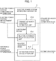
- FIG. 1 is a functional block diagram of an electric power system monitoring apparatus.
- An electric power system monitoring apparatus 1 is configured of a computer device as described later in FIG. 2 .
- the electric power system monitoring apparatus 1 includes, for example, a dynamic behavior constant estimation unit F10, a relative accuracy calculation unit F11, and an estimation error calculation unit F12.
- the electric power system monitoring apparatus 1 receives inputs of an electric power system measurement value that is an example of "a measurement signal obtained from an electric power system", electric power system configuration information, and reference power generator information that is an example of "reference dynamic behavior information”, and outputs a dynamic behavior constant estimation value and an estimation error.
- the dynamic behavior constant estimation unit F10 estimates a dynamic behavior constant based on an electric power system measurement value and electric power system configuration information, and outputs the dynamic behavior constant as a dynamic behavior constant estimation value.
- the relative accuracy calculation unit F11 calculates a relative accuracy index that indicates the accuracy of the dynamic behavior constant estimation value from the electric power system measurement value and a matrix of coefficients obtained from the dynamic behavior constant estimation unit F10.
- the estimation error calculation unit F12 estimates an error of the dynamic behavior constant estimation value from the relative accuracy index, the dynamic behavior constant estimation value, and reference power generator information, and outputs the error as an estimation error.
- FIG. 2 is a block diagram of devices of a system including the electric power system monitoring apparatus 1.
- the electric power system monitoring apparatus 1 is a computer device including, for example, a processor 100, a memory 101, a communication interface (in the drawing, I/F) 102, interfaces 103 and 104, and a user interface 105.
- the memory 101 includes a main storage device and an auxiliary storage device.
- the memory 101 stores computer programs to implement the functions F10 to F12 illustrated in FIG. 1 and a table that manages information.
- the communication interface 102 is a device that communicates with a communication circuit 4.
- the interface 103 is a device that reads electric power system configuration information from an electric power system configuration information DB 5.
- the interface 104 is a device that outputs a dynamic behavior constant estimation value and an estimation error to an estimation information recorder 7.
- the user interface 105 is a device with which a user using the electric power system monitoring apparatus 1 inputs reference power generator information.
- the user interface 105 can also display a screen described later and provide information to the user. Note that, information input-output methods for the electric power system monitoring apparatus 1 are not limited to the example described above.
- electric power system configuration information may be acquired from the database 5, the dynamic behavior constant estimation value and the estimation error may be outputted to the recorder 7, or reference power generator information may be acquired.
- Various quantities of states of an electric power system 2 such as voltages, frequencies, and electric power, are measured by a measuring device 3, and are inputted as electric power system measurement values to the electric power system monitoring apparatus 1 through the communication circuit 4.
- the electric power system configuration information that indicates the configuration of the electric power system 2 includes, for example, a system topology, the specifications of a main power generator, and any other data.
- the electric power system configuration information is recorded on the electric power system configuration information DB (database) 5, and is read by the electric power system monitoring apparatus 1.
- a reference power generator information setting unit. 6 sets a power generator to be a reference for calculating estimation errors as reference power generator information to the electric power system monitoring apparatus 1.
- the dynamic behavior constant estimation value and the estimation error outputted from the electric power system monitoring apparatus 1 are recorded on the estimation information recorder 7.
- the dynamic behavior constant estimation value is inputted to an electric power system analyzer 8 and used for stability analysis at the electric power system analyzer 8
- the dynamic behavior constant estimation value and the estimation error are stored on the estimation information recorder 7 for showing the reliability of the analysis result.
- FIG. 3 is a schematic diagram of the electric power system 2 that is illustrated as a four generator system.
- the electric power system 2 includes one electric power line 21A, another electric power line 21B, a connecting wire 22 that connects the electric power lines 21A and 21B to each other as necessary, power generator nodes 23A of two generators connected to the one electric power line 21A, and power generator nodes 23B of two generators connected to the other electric power line 21B.
- the electric power lines 21A and 21B are referred to as the electric power line 21, and the power generator nodes 23A and 23B are referred to as the power generator node 23, unless otherwise specified.
- the power generator node 23 is an interconnection node of a power generator alone or a contraction power generator.
- Inputs to the dynamic behavior constant estimation unit F10 are the electric power system measurement value and the electric power system configuration information.
- the electric power system measurement value is time series data, such as phase difference angles and angular velocity measured by a phase measuring device and an electric power demand by a load.
- the electric power system configuration information is system topologies showing the connection relationship of the electric power system and known dynamic behavior constants, for example.
- the dynamic behavior constant estimation unit F10 configures a state space model expressed in Equations 1 and 2 below using the electric power system measurement value and the electric power system configuration information.
- the dynamic behavior constant estimation value is calculated by correcting a known dynamic behavior constant (in the following, referred to as an initial dynamic behavior constant) in the initial state in calculation.
- the state vector x is the phase difference angle and the angular velocity from the equilibrium point of the node of the electric power system.
- the input vector u is the machine input or the load demand of the power generator node.
- the state matrix A corresponds to the coefficient matrix of a differential equation relating to a time variation in the state vector x.
- the state matrix A is configured including an inertia constant M_n, a damping factor D_n, and a synchronizing power coefficient K_nm based on the system topology. Numerical subscripts n and m express power generator node numbers.
- the input matrix B is configured including the inertia constant M_n based on the system topology.
- the output vector y is a value that the state vector x is directly measured.
- the output matrix C is a unit matrix
- the direct matrix D is a zero matrix.
- e is the disturbance vector.
- Equations 3 and 4 To the state space model expressed by Equations 1 and 2, the disturbance observer is configured by Equations 3 and 4 below.
- the vector x' is an extended state vector configured of the state vector x and the disturbance vector e.
- the vector x'_h is the estimation value of the extended state vector x'.
- the matrices A', B', and C' are extended system matrices corresponding to the extended state vector x'.
- the matrix L is an observer gain.
- the sequential calculation of Equation 4 obtains the estimation value of the extended state vector x', i.e., the estimation values of the state vector x and the disturbance vector e.
- the disturbance vector e is decomposed as in Equation 5 below.
- the state vector x, the input vector u, the disturbance vector e, and the external disturbance vector r are explicitly pointed out as time series data, and are written in x(t), u(t), e(t), and r(t).
- the matrices ⁇ A and ⁇ B are deviation matrices corresponding to deviations from the true values of the state matrix A and the input matrix B. As described above, in the disturbance observer, the deviation matrices are included in the disturbance vector.
- the deviations are calculated at the regression analysis of Equations 6 and 7 below on the basis of the premise that time series data of the individual elements of the state vector x, the input vector u, and the external disturbance vector r, is linearly independent from one another.
- trans () expresses the transpose operation
- inv () expresses the inverse matrix operation
- e_i(t) expresses time series data of the ith element of the disturbance vector estimation value.
- ⁇ A_ij expresses the (i,j) element of the deviation matrix ⁇ A, and the same thing is applied to ⁇ B_ij.
- x_j (t) expresses time series data of the jth element of the state vector x, and the same thing is applied to u_j(t).
- the estimation values of AA_ij and AB_ij obtained by solving Equations 6, 7, and 8 are expressed as the functions of the inertia constant deviation ⁇ M_n, the damping factor deviation ⁇ D_n, and the synchronizing power coefficient deviation ⁇ K_nm.
- the estimation values of ⁇ M_n, ⁇ D_n, and ⁇ K_nm can be calculated by solving the simultaneous equations of the estimation values of ⁇ A_ij and ⁇ B_ij. From the arithmetic operations above, the dynamic behavior constant estimation unit F10 outputs the dynamic behavior constant estimation values.
- the relative accuracy calculation unit F11 calculates the relative accuracy index that indicates the accuracy of the estimation values of the dynamic behavior constant deviations, focusing attention on Equations 5, 6, 7, and 8.
- the disturbance vector e is the linear synthesis of the state vector x, the input vector u, and the external disturbance vector r using the deviation matrices ⁇ A and ⁇ B as coefficients.
- the signal has a stronger strength in the linear synthesis of Equation 5.
- a signal having a stronger strength in Equation 5 is not prone to be affected by the external disturbance vector r, and the deviation matrix element that is the coefficient of the signal can be highly accurately calculated. Therefore, with a signal having a stronger strength in Equation 5, the corresponding dynamic behavior constant deviation can also be highly accurately calculated.
- an estimation accuracy index ⁇ is defined as in Equation 9.
- log10 expresses a common logarithm
- var expresses a variance.
- Equation 9 the direct calculation of Equation 9 is not allowed. Therefore, in the embodiment, A_ij and B_ij are used instead of ⁇ A_ij and ⁇ B_ij, and a relative accuracy index ⁇ ' is defined as in Equations 10 and 11 below.
- ⁇ ′ _ ij log 10 var G _ ij ⁇ Z _ j t
- G _ i A _ i 1 , A _ i 2 , ... , B _ i 1 , B _ i 2 , ...
- the value of the relative accuracy index ⁇ ' is different from the value of the estimation accuracy index ⁇ .
- the values of ⁇ A_ij and ⁇ B_ij are respectively proportional to the values of A_ij and B_ij, the relative size relationship between the indexes ⁇ ' and ⁇ is the same order. Actually, this assumption is not strictly held. However, Equations 9 and 10 are expressed by the common logarithm.
- the relative accuracy index ⁇ ' is an index that approximates the size relationship of the estimation accuracy index ⁇ in the order.
- the relative accuracy index is described by the variance of ⁇ G_ij ⁇ Z_j(t), which is non-limiting.
- the relative accuracy index may be normalized using the variance of the external disturbance r(t).
- the relative accuracy index is normalized using the variance of the estimation value of the disturbance e(t), and hence the relative accuracy index can be described as the magnitude of the signal strength to disturbance.
- the description using the variance may be substituted by another statistical index that indicates signal strength.
- the estimation error calculation unit F12 calculates estimation errors by the following process based on reference power generator information that is an input to the electric power system monitoring apparatus 1, the dynamic behavior constant estimation value calculated at the dynamic behavior constant estimation unit F10, and the relative accuracy index ⁇ ' calculated at the relative accuracy calculation unit F11.
- FIG. 4 shows an example of a table T10 that manages reference power generator information.
- the reference power generator information management table T10 manages reference power generator nodes having a known dynamic behavior constant, for example, associating a node number C100 with a dynamic behavior constant C101 to be the reference.
- the power generator node having a known dynamic behavior constant is the power generator node of a single power generator having a calibrated constant or the power generator node of a distributed power supply whose dynamic behavior is simulated in a pseudo manner by power electronics control, for example.
- FIG. 5 is an example of a dynamic behavior constant estimation value management table T11 that manages dynamic behavior constant estimation values calculated at the dynamic behavior constant estimation unit F10.
- the dynamic behavior constant estimation value management table T11 manages a power generator node number C110 that identifies the power generator node and a dynamic behavior constant estimation value in association with each other.
- the inertia constants are shown as examples of dynamic behavior constants.
- similar tables are also provided for the damping factor and the synchronizing power coefficient.
- a reference estimation error ⁇ can be calculated on the reference power generator node as in Equation 12 below.
- the inertia constant will be described as an example.
- ⁇ (M)_n is a reference estimation error relating to the inertia constant of a reference power generator node n.
- M0_n and ⁇ M_n are an initial dynamic behavior constant and a deviation estimation value, respectively, relating to the inertia constant of the reference power generator node n at the dynamic behavior constant estimation unit F10.
- M_n is the inertia constant of the reference power generator node n.
- FIG. 6 shows graphs that plot a relative accuracy index ⁇ ' (M)_n calculated at the relative accuracy calculation unit F11 and the reference estimation error ⁇ (M)_n obtained from Equation 12. Note that, ⁇ ' (M)_n is an element corresponding to the inertia constant of the power generator node n in the relative accuracy index ⁇ '_ij in Equation 10.
- the relationship between the relative accuracy index ⁇ ' (M)_n and the reference estimation error ⁇ (M)_n is approximated to a straight line L1, and hence the relative accuracy index of another power generator node can be converted into an estimation error.
- the reference estimation error ⁇ (M)_n is weighted on the plurality of plots P, and approximated to a straight line L2, and then the relative accuracy index is converted into an estimation error.
- an approximation to a curve L3 can also convert the relative accuracy index into an estimation error, instead of an approximation to a straight line.
- the estimation error calculation unit F12 associates the relative accuracy index with the estimation error, and calculates estimation errors relating to the dynamic behavior constants of the power generator nodes.
- plotting a reference estimation error on a number line allows the determination of the size of the estimation error of another power generator node to the reference estimation error.
- This method is effective in estimating the dynamic behavior constants all the time, for example, in the case of adopting only the estimation result of the dynamic behavior constant of a power generator having an estimation error smaller than the reference estimation error at the timing at which the reference estimation error becomes sufficiently small.
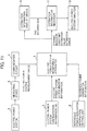
- FIG. 7 is a flowchart of a process performed by the electric power system monitoring apparatus 1.
- the electric power system monitoring apparatus 1 performs an initialization process, and sets an initial dynamic behavior constant (S10).
- the electric power system monitoring apparatus 1 estimates a dynamic behavior constant using the dynamic behavior constant estimation unit F10 (S11).
- the dynamic behavior constant estimation unit F10 outputs a dynamic behavior constant estimation value to the estimation information recorder 7 described in FIG. 1 .
- the estimation information recorder 7 records the received dynamic behavior constant estimation value in association with an estimation error that is to be received in Step S13.
- the electric power system monitoring apparatus 1 calculates a relative accuracy index that is an index indicating the accuracy of the dynamic behavior constant estimation value using the relative accuracy calculation unit F11 (S12).
- the electric power system monitoring apparatus 1 calculates an estimation error using the estimation error calculation unit F12 (S13).
- the estimation error calculation unit F12 sends the calculated estimation error to the estimation information recorder 7.
- the electric power system monitoring apparatus 1 performs Steps S10 to S13 described above to output the dynamic behavior constant estimation value and the estimation error to the estimation information recorder 7 and other devices.
- Step S14 is performed as an additional process.
- the electric power system monitoring apparatus 1 compares a preset error threshold with the estimation error, and updates the initial dynamic behavior constant for the dynamic behavior constant whose estimation error is below the error threshold.
- the electric power system monitoring apparatus 1 repeatedly performs Steps S11 to S14 to sequentially improve the accuracy (estimation accuracy) of the initial dynamic behavior constant.
- the estimation error that is previously estimated may be used as a new error threshold.
- dynamic behavior constants can be estimated using measurement signals obtained from the electric power system, and the accuracy of the estimation results of the dynamic behavior constants can be obtained. Consequently, in accordance with the embodiment, after the accuracy of a dynamic behavior constant estimation value is grasped, the process using the dynamic behavior constant estimation value can be performed.
- the dynamic behavior constant is estimated from given weak measurement signals observed in the electric power system, and the accuracy of the estimated dynamic behavior constant can be determined. Therefore, the electric power system monitoring apparatus 1 can use the dynamic behavior constant estimation value after confirming the estimation error, and can monitor the state of the electric power system.
- the accuracy of the dynamic behavior constant estimation value can be determined.
- the accuracy of the initial dynamic behavior constant can be sequentially improved.
- the electric power system monitoring apparatus 1 enables the automatic improvement of the performance of monitoring the electric power system.
- the reliability and user usability of the electric power system monitoring apparatus 1 can be improved.
- FIGS. 8 to 10 a second embodiment will be described. Since the following embodiments including the second embodiment correspond to exemplary modifications of the first embodiment, differences from the first embodiment will be mainly described. In the embodiment, the case will be described in which reference power generator information is generated in the inside of an electric power system monitoring apparatus 1A.
- FIG. 8 shows the functional configuration of the electric power system monitoring apparatus 1A according to the embodiment.
- the electric power system monitoring apparatus 1A includes a dynamic behavior constant estimation unit F10, a relative accuracy calculation unit F11, and an estimation error calculation unit F12 described in FIG. 1 .
- the electric power system monitoring apparatus 1A according to the embodiment further includes a reference power generator information generating unit F13 to generate reference power generator information.
- the reference power generator information generating unit F13 receives an input of a relative accuracy index calculated at the relative accuracy calculation unit F11, generates reference power generator information by calculation, and outputs the generated reference power generator information to the estimation error calculation unit F12.
- FIG. 9 shows an example of a method for generating reference power generator information.
- the description is made in which the relative accuracy index ⁇ ' (M)_n relating to the inertia constants of the power generator nodes is taken as an example.
- the reference power generator information generating unit F13 selects one or a plurality of the reference power generator nodes G1 and G2 in the descending order of the mean value of the relative accuracy index in (2) in FIG. 9 .
- the reference power generator information generating unit F13 then calculates statistical representative values, such as mean values and medians, on the inertia constants of the reference power generator node G1 and G2 in (1) in FIG. 9 , and outputs the calculation result as reference power generator information to the estimation error calculation unit F12.
- reference power generator information is generated based on the relative accuracy index that indicates the accuracy of the inertia constant estimation value as described above. Since the reference power generator information thus generated is used instead of reference power generator information set in the first embodiment, the reference power generator information can also be referred to as alternate reference power generator information.
- a configuration may be possible in which a statistical range, such as standard deviation, is calculated on the inertia constants of the alternate reference power generator nodes G1 and G2 in (1) in FIG. 9 , and the calculation result is used as the alternate value of the reference estimation error in Equation 12.
- FIG. 10 is a flowchart of an electric power system monitoring process executed by the electric power system monitoring apparatus 1A according to the embodiment. This process includes an iteration process S20 for calculating statistic values at the reference power generator information generating unit F13.
- the electric power system monitoring apparatus 1A executes an initialization process for setting an initial dynamic behavior constant (S10).
- the electric power system monitoring apparatus 1A executes a dynamic behavior constant estimation process (S11) at the dynamic behavior constant estimation unit F10 and a relative accuracy index calculation process (S12) at the relative accuracy calculation unit F11 as the iteration process (S20).
- the electric power system monitoring apparatus 1A executes Steps S11 and S12 until the number of times of execution reaches a pre-specified number of times or until the statistical representative values of the dynamic behavior constant converge. Upon finishing the iteration process, the electric power system monitoring apparatus 1A instructs the reference power generator information generating unit F13 to generate reference power generator information (S21).
- the estimation error calculation unit F12 calculates an estimation error based on the reference power generator information generated at the reference power generator information generating unit F13 and the relative accuracy index calculated at the relative accuracy calculation unit F11 (S13).
- the embodiment thus configured also exerts the operation and effect similar to the first embodiment.
- reference power generator information can be generated in the inside of the electric power system monitoring apparatus 1A.
- the dynamic behavior constant that is reference power generator information generated at the reference power generator information generating unit F13 according to the embodiment is not always accurate.
- the dynamic behavior constant can be estimated, and the accuracy of the dynamic behavior constant estimation value can be calculated. Accordingly, user usability is improved.
- the electric power system monitoring apparatus 1 is in connection to an estimation information display device 9 to provide a dynamic behavior constant estimation value and its error to a user.
- the estimation information display device 9 receives a dynamic behavior constant estimation value and an estimation error from the electric power system monitoring apparatus 1, and displays the value and the error on a screen. The estimation information display device 9 then outputs tag information to an estimation information recorder 7.
- the estimation information display device 9 may be configured as a computer separate from the electric power system monitoring apparatus 1, or may be provided as the function of the electric power system monitoring apparatus 1 in the inside of the electric power system monitoring apparatus 1. Alternatively, the estimation information display device 9 may be integrated with the estimation information recorder 7. Note that, the estimation information recorder 7 and the estimation information display device 9 may be provided in the inside of the electric power system monitoring apparatus 1.
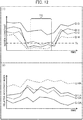
- FIG. 12 shows exemplary screens displayed by the estimation information display device 9.
- the horizontal axis in (1) and (2) in FIG. 12 expresses a time base. Every time when Steps S11 to S13 are repeated in the processes in FIG. 7 , the time base goes forward.
- the vertical axis in (1) in FIG. 12 expresses the size of the estimation error of the dynamic behavior constant.
- the vertical axis in (2) in FIG. 12 expresses the size of the relative accuracy index.
- Solid lines G11 and G12 in (1) in FIG. 12 express reference estimation errors relating to reference power generator nodes
- dotted lines G13 and G14 express estimation errors calculated at the estimation error calculation unit F12 on the other power generator nodes .
- Thick lines G11A and G12A in (2) in FIG. 12 are relative accuracy indexes relating to reference power generator nodes
- thin lines G13A and G14A are relative accuracy indexes relating to the other power generator nodes.
- the estimation error of the dynamic behavior constant and the relative accuracy index are changed depending on the size of the signal strength of the electric power system measurement value inputted to the electric power system monitoring apparatus 1.
- the selective extraction of the calculation result is necessary at the timing at which the signal strength of the electric power system measurement value is large.
- filtering is performed on the estimation error calculated at the estimation error calculation unit F12 by setting a threshold Th on the screen in (1) in FIG. 12 .
- Th on the screen in (1) in FIG. 12 .
- a method may be possible with which an estimation result with a large relative accuracy index is selected on each of the power generator nodes on the time base in (2) in FIG. 12 , an estimation value corresponding to the estimation result is extracted, and hence a dynamic behavior constant estimation value of relatively high estimation accuracy can be obtained.
- the dynamic behavior constant estimation value of high estimation accuracy can also be manually extracted. For example, a user (an operator) selects, on the screen in (1) in FIG. 12 , a period TS for which reference estimation errors are sequentially small.
- the electric power system monitoring apparatus 1 extracts an estimation value on a power generator node having an estimation error smaller than the threshold Th or on a power generator node having a relative accuracy index greater than the reference power generator node in the selected period TS.
- the estimation value can be extracted using the estimation information display device 9.
- tag information is added.
- the extracted estimation value is sorted in association with the dynamic behavior constant estimation value and the estimation error at the estimation information recorder 7.
- the electric power system analyzer 8 can perform calculation based on the dynamic behavior constant estimation value of higher accuracy in system analysis using the dynamic behavior constant estimation value having tag information.
- system analysis include analysis of eigenvalues relating to the swing of the electric power system and control parameter design for reducing swings.
- the embodiment thus configured also exerts the operation and effect similar to the first embodiment.
- the electric power system can be monitored using the dynamic behavior constant estimation value calculated at the timing at which the signal strength of the electric power system measurement value is strong. Accordingly, reliability and usability are improved.
- FIG. 13 a fourth embodiment will be described.
- an example of utilization of the electric power system monitoring apparatus 1 will be described.
- the electric power and the phase angle which are the physical quantities of the electric power system 2, are measured by the measuring device 3.
- the electric power system monitoring apparatus 1 receives inputs of this measured information, reference power generator information, and electric power system configuration information, and calculates an estimation value of the dynamic behavior constant and its estimation error.
- the electric power system monitoring apparatus 1 outputs the estimation value of a dynamic behavior constant (the inertia constant, the damping factor, and the synchronizing power coefficient) having high accuracy in the calculation results to the estimation information recorder 7.
- An electric power system controller 10 calculates a control parameter for a stabilizer 11 using dynamic behavior constants recorded on the estimation information recorder 7, and outputs the parameter.
- the stabilizer 11 outputs active power or reactive power, for example, to the electric power system 2 based on the control parameter.
- the electric power system monitoring apparatus 1 estimates the dynamic behavior constants of the electric power system 2 all the time, and the electric power system controller 10 determines the control parameter for the stabilizer 11 using estimation values of high accuracy among estimation values. Accordingly, in the embodiment, the synchronization stability of the electric power system 2 can be improved.
- the present invention is not limited to the foregoing embodiments, and can include various exemplary modifications.
- the embodiments are described in detail for easily understanding the present invention.
- the embodiments are not necessarily limited to ones having all the described configurations.
- the configuration of an embodiment can also be replaced by the configuration of another embodiment.
- the configuration of another embodiment can also be added to the configuration of an embodiment.
- another configuration can be added, removed, and replaced.
Landscapes
- Engineering & Computer Science (AREA)
- Power Engineering (AREA)
- Physics & Mathematics (AREA)
- General Physics & Mathematics (AREA)
- Supply And Distribution Of Alternating Current (AREA)
- Remote Monitoring And Control Of Power-Distribution Networks (AREA)
Claims (15)
- Überwachungsvorrichtung für ein Stromversorgungssystem, die Folgendes umfasst:eine Einheit zur Schätzung einer Konstante des dynamischen Verhaltens, um eine vorbestimmte Konstante des dynamischen Verhaltens aus einem Messsignal zu schätzen, das von einem Stromversorgungssystem erhalten worden ist;dadurch gekennzeichnet, dass sie ferner Folgendes umfasst:eine Einheit zur Berechnung einer relativen Genauigkeit, um aus dem Messsignal einen Index der relativen Genauigkeit zu berechnen, der die Genauigkeit des Schätzwertes der Konstante des dynamischen Verhaltens anzeigt, der von der Einheit zur Schätzung der Konstante des dynamischen Verhaltens geschätzt worden ist; undeine Einheit zur Berechnung eines Schätzfehlers, um einen Schätzfehler aus Referenzinformationen des dynamischen Verhaltens, dem Schätzwert der Konstante des dynamischen Verhaltens und dem Index der relativen Genauigkeit zu berechnen.
- Überwachungsvorrichtung für ein Stromversorgungssystem nach Anspruch 1,
wobei die Einheit zur Berechnung der relativen Genauigkeit den Index der relativen Genauigkeit basierend auf einer Signalstärke des Messsignals berechnet. - Überwachungsvorrichtung für ein Stromversorgungssystem nach Anspruch 1,
wobei die Einheit zur Berechnung der relativen Genauigkeit den Index der relativen Genauigkeit basierend auf einem Produkt aus der Signalstärke des Messsignals und aus einem Koeffizienten einer Differenzialgleichung, die ein dynamisches Verhalten des Stromversorgungssystems ausdrückt, berechnet. - Überwachungsvorrichtung für ein Stromversorgungssystem nach Anspruch 1,
wobei die vorbestimmte Konstante des dynamischen Verhaltens eine erste Konstante des dynamischen Verhaltens und eine zweite Konstante des dynamischen Verhaltens enthält,
das Messsignal ein erstes Messsignal, das verwendet wird, um die erste Konstante des dynamischen Verhaltens zu schätzen, und ein zweites Messsignal enthält, das verwendet wird, um die zweite Konstante des dynamischen Verhaltens zu schätzen, und
die Einheit zur Berechnung einer relativen Genauigkeit den Index der relativen Genauigkeit basierend auf einem Größenverhältnis zwischen Signalstärke des ersten Messsignals und der Signalstärke des zweiten Messsignals berechnet. - Überwachungsvorrichtung für ein Stromversorgungssystem nach Anspruch 1,
wobei die Referenzinformationen des dynamischen Verhaltens eine Zahl enthalten, die einen Referenz-Stromgeneratorknoten, der eine bekannte Konstante des dynamischen Verhaltens aufweist, und die Konstante des dynamischen Verhaltens des Referenz-Stromgeneratorknotens anzeigt. - Überwachungsvorrichtung für ein Stromversorgungssystem nach Anspruch 5,
wobei der Referenz-Stromgeneratorknoten einem einzelnen Stromgeneratorknoten, der eine kalibrierte Konstante des dynamischen Verhaltens aufweist, oder einem verteilten Stromverteilerknoten mit einem dynamischen Verhalten eines synchronen Generators, das pseudosimuliert ist, entspricht. - Überwachungsvorrichtung für ein Stromversorgungssystem nach Anspruch 5,
wobei die Einheit zur Berechnung eines Schätzfehlers:einen Referenzschätzfehler berechnet, der einem Schätzfehler der Konstante des dynamischen Verhaltens bezüglich des Referenz-Stromgeneratorknotens entspricht, durch Vergleichen des Schätzwerts der Konstante des dynamischen Verhaltens mit den Referenzinformationen des dynamischen Verhaltens, undden Index der relativen Genauigkeit eines weiteren Stromgeneratorknotens mit Ausnahme des Referenz-Stromgeneratorknotens in einen Schätzfehler umwandelt, durch Ausdrücken des berechneten Referenz-Schätzfehlers als Funktion des Index der relativen Genauigkeit. - Überwachungsvorrichtung für ein Stromversorgungssystem nach Anspruch 7,
wobei während der wiederholten Ausführung der Prozesse der Einheit zur Schätzung der Konstante des dynamischen Verhaltens, der Einheit zur Berechnung der relativen Genauigkeit und der Einheit zur Berechnung des Schätzfehlers jedes Mal, wenn die Prozesse durchgeführt werden, ein Stromgeneratorknoten, der den kleinsten Schätzfehler aufweist, und ein Schätzwert der Konstante des dynamischen Verhaltens des Stromgeneratorknotens zu den Referenzinformationen des dynamischen Verhaltens hinzugefügt werden. - Überwachungsvorrichtung für ein Stromversorgungssystem nach Anspruch 1, das ferner eine Einheit zur Erzeugung von Referenzinformationen des dynamischen Verhaltens umfasst, um die Referenzinformationen des dynamischen Verhaltens aus dem Index der relativen Genauigkeit zu berechnen.
- Überwachungsvorrichtung für ein Stromversorgungssystem nach Anspruch 9,
wobei die Einheit zur Erzeugung von Referenzinformationen des dynamischen Verhaltens die Referenzinformationen des dynamischen Verhaltens unter Verwendung eines Stromgeneratorknotens, der den besten Index der relativen Genauigkeit aufweist, und einer Konstante des dynamischen Verhaltens des Stromgeneratorknoten erzeugt. - Überwachungsvorrichtung für ein Stromversorgungssystem nach Anspruch 9,
wobei die Prozesse der Einheit zur Schätzung einer Konstante des dynamischen Verhaltens, der Einheit zur Berechnung einer relativen Genauigkeit und der Einheit zur Berechnung eines Schätzfehlers wiederholt durchgeführt werden, und
die Einheit zur Erzeugung von Referenzinformationen des dynamischen Verhaltens die Referenzinformationen des dynamischen Verhaltens unter Verwendung eines Stromgeneratorknotens, der einen Mittelwert des besten Index der relativen Genauigkeit aufweist, und einer Konstante des dynamischen Verhaltens des Stromgeneratorknotens erzeugt. - Überwachungsvorrichtung für ein Stromversorgungssystem nach Anspruch 1, das ferner eine Einrichtung zum Anzeigen von Schätzinformationen umfasst, um den Index der relativen Genauigkeit und den Schätzfehler anzuzeigen.
- Überwachungsvorrichtung für ein Stromversorgungssystem nach Anspruch 12,
wobei unter mehreren der Schätzwerte der Konstante des dynamischen Verhaltens der Schätzwert der Konstanten des dynamischen Verhaltens ausgegeben wird, wobei der Schätzwert der Konstanten des dynamischen Verhaltens nicht größer ist als ein Schwellenwert, der auf den Schätzfehler eingestellt ist, der durch die Einrichtung zum Anzeigen der Schätzinformationen angezeigt wird. - Überwachungsvorrichtung für ein Stromversorgungssystem nach Anspruch 12,
wobei in dem Schätzwert der Konstanten des dynamischen Verhaltens ein Ergebnis mit hoher Genauigkeit durch das Einstellen eines Schwellenwertes auf den Index der relativen Genauigkeit auf einem Bildschirm der Einrichtung zum Anzeigen der Schätzinformationen selektiv ausgegeben wird. - Überwachungsverfahren für ein Stromversorgungssystem unter Verwendung eines Computers,
wobei der Computer:ein Messsignal von einer Messeinrichtung, die in einem Stromversorgungssystem vorgesehen ist, erfasst;eine vorbestimmte Konstante des dynamischen Verhaltens als einen Schätzwert der Konstanten des dynamischen Verhaltens aus dem Messsignal schätzt;wobei das Verfahren dadurch gekennzeichnet ist, dass der Computer ferner:einen Index der relativen Genauigkeit berechnet, der eine Genauigkeit des Schätzwerts der Konstanten des dynamischen Verhaltens aus dem Messwert anzeigt;Referenzinformationen des dynamischen Verhaltens erfasst, die einer Referenz des Schätzwerts der Konstanten des dynamischen Verhaltens entspricht; undeinen Schätzfehler aus den Referenzinformationen des dynamischen Verhaltens, dem Schätzwert der Konstanten des dynamischen Verhaltens und dem Index der relativen Genauigkeit berechnet.
Applications Claiming Priority (2)
| Application Number | Priority Date | Filing Date | Title |
|---|---|---|---|
| JP2015228471A JP6374371B2 (ja) | 2015-11-24 | 2015-11-24 | 電力系統監視装置および電力系統監視方法 |
| PCT/JP2016/083151 WO2017090428A1 (ja) | 2015-11-24 | 2016-11-09 | 電力系統監視装置および電力系統監視方法 |
Publications (3)
| Publication Number | Publication Date |
|---|---|
| EP3382840A1 EP3382840A1 (de) | 2018-10-03 |
| EP3382840A4 EP3382840A4 (de) | 2019-08-07 |
| EP3382840B1 true EP3382840B1 (de) | 2020-03-18 |
Family
ID=58764001
Family Applications (1)
| Application Number | Title | Priority Date | Filing Date |
|---|---|---|---|
| EP16868376.1A Active EP3382840B1 (de) | 2015-11-24 | 2016-11-09 | Vorrichtung zur überwachung eines energiesystems und verfahren zur überwachung eines energiesystems |
Country Status (4)
| Country | Link |
|---|---|
| US (1) | US11035892B2 (de) |
| EP (1) | EP3382840B1 (de) |
| JP (1) | JP6374371B2 (de) |
| WO (1) | WO2017090428A1 (de) |
Families Citing this family (4)
| Publication number | Priority date | Publication date | Assignee | Title |
|---|---|---|---|---|
| KR102078652B1 (ko) * | 2013-11-13 | 2020-02-19 | 삼성전자주식회사 | 스마트플러그 장치에서 이벤트 감지장치 및 방법 |
| JP7358837B2 (ja) * | 2019-08-21 | 2023-10-11 | 東京電力ホールディングス株式会社 | 慣性推定装置、慣性推定プログラム及び慣性推定方法 |
| JP7358836B2 (ja) * | 2019-08-21 | 2023-10-11 | 東京電力ホールディングス株式会社 | 慣性推定装置、慣性推定プログラム及び慣性推定方法 |
| JP7593141B2 (ja) * | 2021-01-26 | 2024-12-03 | 東京電力ホールディングス株式会社 | 情報処理装置、情報処理方法、及びプログラム |
Family Cites Families (13)
| Publication number | Priority date | Publication date | Assignee | Title |
|---|---|---|---|---|
| JP3174525B2 (ja) * | 1997-03-07 | 2001-06-11 | 三菱電機株式会社 | モデリング方法、予測方法及び系統安定化制御方法 |
| JPH10271686A (ja) * | 1997-03-25 | 1998-10-09 | Tokyo Electric Power Co Inc:The | 電力系統の安定化装置 |
| JP4080952B2 (ja) * | 2003-06-02 | 2008-04-23 | 三菱電機株式会社 | 周波数測定装置 |
| US7233843B2 (en) * | 2003-08-08 | 2007-06-19 | Electric Power Group, Llc | Real-time performance monitoring and management system |
| JP2006238664A (ja) * | 2005-02-28 | 2006-09-07 | Toshiba Corp | 電力系統の動特性定数推定方法と装置、電力系統解析方法と装置、電力系統安定化方法と装置、およびプログラム |
| US20170046458A1 (en) * | 2006-02-14 | 2017-02-16 | Power Analytics Corporation | Systems and methods for real-time dc microgrid power analytics for mission-critical power systems |
| JP2010193535A (ja) * | 2009-02-16 | 2010-09-02 | Hitachi Ltd | 非線形系統安定化装置 |
| JP2010226906A (ja) * | 2009-03-25 | 2010-10-07 | Tokyo Electric Power Co Inc:The | 電力系統解析モデル評価装置 |
| US20120022713A1 (en) * | 2010-01-14 | 2012-01-26 | Deaver Sr Brian J | Power Flow Simulation System, Method and Device |
| US9863985B2 (en) * | 2012-04-13 | 2018-01-09 | Regents Of The University Of Minnesota | State estimation of electrical power networks using semidefinite relaxation |
| JP5292505B1 (ja) * | 2012-11-20 | 2013-09-18 | 株式会社東芝 | 行動推定装置、閾値算出装置、行動推定方法、行動推定プログラム |
| US9658260B2 (en) * | 2013-09-04 | 2017-05-23 | Abb Schweiz Ag | Power system state estimation using a two-level solution |
| JP6144611B2 (ja) * | 2013-12-03 | 2017-06-07 | 株式会社日立製作所 | 配電系統の状態推定装置、状態推定方法、および状態推定プログラム |
-
2015
- 2015-11-24 JP JP2015228471A patent/JP6374371B2/ja not_active Expired - Fee Related
-
2016
- 2016-11-09 WO PCT/JP2016/083151 patent/WO2017090428A1/ja not_active Ceased
- 2016-11-09 US US15/773,022 patent/US11035892B2/en not_active Expired - Fee Related
- 2016-11-09 EP EP16868376.1A patent/EP3382840B1/de active Active
Non-Patent Citations (1)
| Title |
|---|
| None * |
Also Published As
| Publication number | Publication date |
|---|---|
| EP3382840A1 (de) | 2018-10-03 |
| WO2017090428A1 (ja) | 2017-06-01 |
| EP3382840A4 (de) | 2019-08-07 |
| JP6374371B2 (ja) | 2018-08-15 |
| US11035892B2 (en) | 2021-06-15 |
| US20180313876A1 (en) | 2018-11-01 |
| JP2017099119A (ja) | 2017-06-01 |
Similar Documents
| Publication | Publication Date | Title |
|---|---|---|
| US9864820B2 (en) | Generator dynamic model parameter estimation and tuning using online data and subspace state space model | |
| EP3382840B1 (de) | Vorrichtung zur überwachung eines energiesystems und verfahren zur überwachung eines energiesystems | |
| US7107187B1 (en) | Method for modeling system performance | |
| US9746511B2 (en) | Estimating the locations of power system events using PMU measurements | |
| EP3477404B1 (de) | Parameterkonditionierungswerkzeug für das stromsystemmodell | |
| US12278490B2 (en) | Power system measurement based model calibration with enhanced optimization | |
| WO2020197533A1 (en) | Surrogate of a simulation engine for power system model calibration | |
| CA2867187A1 (en) | Systems and methods for detecting, correcting, and validating bad data in data streams | |
| US10282272B2 (en) | Operation management apparatus and operation management method | |
| US11169188B2 (en) | Low-observability matrix completion | |
| AU2014281126A1 (en) | Source impedance estimation | |
| CN116105885B (zh) | 一种核电用电气设备状态监测方法及系统 | |
| KR102226677B1 (ko) | 전력계통의 하모닉 임피던스 측정장치 및 측정방법 | |
| US20190379237A1 (en) | Smart Outlet System with Fast Frequency Tracking for Power System Frequency Control Using Distributed Appliances | |
| JP6756603B2 (ja) | 電力系統の状態推定装置および状態推定方法 | |
| CN111695319A (zh) | 一种实时补偿连接器串联回路电感的方法和设备 | |
| US11133674B2 (en) | System operation support device and method in power system, and wide-area monitoring protection control system | |
| JP2020047846A (ja) | データ処理方法、データ処理装置、データ処理システム、およびデータ処理プログラム | |
| CN116540038B (zh) | 一种电容器组的绝缘状态监测方法和装置 | |
| CN114731325A (zh) | 智能电子设备的配置方法 | |
| Sairam et al. | Contingency Ranking in a Power Transmission System Using ZIP Load Modeling | |
| CN115573866A (zh) | 惯性量值处理方法、装置、计算机设备、存储介质和产品 | |
| Pijpers et al. | Data acquisition and processing for power hardware-in-the loop simulations of LV distribution feeders | |
| Sun et al. | An automatic design technique for hardware system of ATS | |
| AU2021421464B2 (en) | Storage battery management device and storage battery management method |
Legal Events
| Date | Code | Title | Description |
|---|---|---|---|
| STAA | Information on the status of an ep patent application or granted ep patent |
Free format text: STATUS: THE INTERNATIONAL PUBLICATION HAS BEEN MADE |
|
| PUAI | Public reference made under article 153(3) epc to a published international application that has entered the european phase |
Free format text: ORIGINAL CODE: 0009012 |
|
| STAA | Information on the status of an ep patent application or granted ep patent |
Free format text: STATUS: REQUEST FOR EXAMINATION WAS MADE |
|
| 17P | Request for examination filed |
Effective date: 20180625 |
|
| AK | Designated contracting states |
Kind code of ref document: A1 Designated state(s): AL AT BE BG CH CY CZ DE DK EE ES FI FR GB GR HR HU IE IS IT LI LT LU LV MC MK MT NL NO PL PT RO RS SE SI SK SM TR |
|
| AX | Request for extension of the european patent |
Extension state: BA ME |
|
| DAV | Request for validation of the european patent (deleted) | ||
| DAX | Request for extension of the european patent (deleted) | ||
| A4 | Supplementary search report drawn up and despatched |
Effective date: 20190708 |
|
| RIC1 | Information provided on ipc code assigned before grant |
Ipc: G01R 19/25 20060101ALI20190702BHEP Ipc: H02J 3/00 20060101AFI20190702BHEP Ipc: H02J 13/00 20060101ALI20190702BHEP |
|
| GRAP | Despatch of communication of intention to grant a patent |
Free format text: ORIGINAL CODE: EPIDOSNIGR1 |
|
| STAA | Information on the status of an ep patent application or granted ep patent |
Free format text: STATUS: GRANT OF PATENT IS INTENDED |
|
| RIC1 | Information provided on ipc code assigned before grant |
Ipc: G01R 19/25 20060101ALI20190930BHEP Ipc: G01R 31/34 20060101ALI20190930BHEP Ipc: H02J 3/00 20060101AFI20190930BHEP Ipc: H02J 13/00 20060101ALI20190930BHEP |
|
| INTG | Intention to grant announced |
Effective date: 20191106 |
|
| GRAJ | Information related to disapproval of communication of intention to grant by the applicant or resumption of examination proceedings by the epo deleted |
Free format text: ORIGINAL CODE: EPIDOSDIGR1 |
|
| GRAP | Despatch of communication of intention to grant a patent |
Free format text: ORIGINAL CODE: EPIDOSNIGR1 |
|
| INTG | Intention to grant announced |
Effective date: 20200109 |
|
| RIN1 | Information on inventor provided before grant (corrected) |
Inventor name: OMI, SHOTA Inventor name: YAMANE, KENICHIROU Inventor name: KUMAGAI, MASATOSHI |
|
| GRAS | Grant fee paid |
Free format text: ORIGINAL CODE: EPIDOSNIGR3 |
|
| GRAA | (expected) grant |
Free format text: ORIGINAL CODE: 0009210 |
|
| STAA | Information on the status of an ep patent application or granted ep patent |
Free format text: STATUS: THE PATENT HAS BEEN GRANTED |
|
| AK | Designated contracting states |
Kind code of ref document: B1 Designated state(s): AL AT BE BG CH CY CZ DE DK EE ES FI FR GB GR HR HU IE IS IT LI LT LU LV MC MK MT NL NO PL PT RO RS SE SI SK SM TR |
|
| REG | Reference to a national code |
Ref country code: GB Ref legal event code: FG4D |
|
| REG | Reference to a national code |
Ref country code: DE Ref legal event code: R096 Ref document number: 602016032302 Country of ref document: DE |
|
| REG | Reference to a national code |
Ref country code: AT Ref legal event code: REF Ref document number: 1247041 Country of ref document: AT Kind code of ref document: T Effective date: 20200415 Ref country code: IE Ref legal event code: FG4D |
|
| PG25 | Lapsed in a contracting state [announced via postgrant information from national office to epo] |
Ref country code: NO Free format text: LAPSE BECAUSE OF FAILURE TO SUBMIT A TRANSLATION OF THE DESCRIPTION OR TO PAY THE FEE WITHIN THE PRESCRIBED TIME-LIMIT Effective date: 20200618 Ref country code: FI Free format text: LAPSE BECAUSE OF FAILURE TO SUBMIT A TRANSLATION OF THE DESCRIPTION OR TO PAY THE FEE WITHIN THE PRESCRIBED TIME-LIMIT Effective date: 20200318 Ref country code: RS Free format text: LAPSE BECAUSE OF FAILURE TO SUBMIT A TRANSLATION OF THE DESCRIPTION OR TO PAY THE FEE WITHIN THE PRESCRIBED TIME-LIMIT Effective date: 20200318 |
|
| REG | Reference to a national code |
Ref country code: NL Ref legal event code: MP Effective date: 20200318 |
|
| PG25 | Lapsed in a contracting state [announced via postgrant information from national office to epo] |
Ref country code: GR Free format text: LAPSE BECAUSE OF FAILURE TO SUBMIT A TRANSLATION OF THE DESCRIPTION OR TO PAY THE FEE WITHIN THE PRESCRIBED TIME-LIMIT Effective date: 20200619 Ref country code: BG Free format text: LAPSE BECAUSE OF FAILURE TO SUBMIT A TRANSLATION OF THE DESCRIPTION OR TO PAY THE FEE WITHIN THE PRESCRIBED TIME-LIMIT Effective date: 20200618 Ref country code: SE Free format text: LAPSE BECAUSE OF FAILURE TO SUBMIT A TRANSLATION OF THE DESCRIPTION OR TO PAY THE FEE WITHIN THE PRESCRIBED TIME-LIMIT Effective date: 20200318 Ref country code: LV Free format text: LAPSE BECAUSE OF FAILURE TO SUBMIT A TRANSLATION OF THE DESCRIPTION OR TO PAY THE FEE WITHIN THE PRESCRIBED TIME-LIMIT Effective date: 20200318 Ref country code: HR Free format text: LAPSE BECAUSE OF FAILURE TO SUBMIT A TRANSLATION OF THE DESCRIPTION OR TO PAY THE FEE WITHIN THE PRESCRIBED TIME-LIMIT Effective date: 20200318 |
|
| REG | Reference to a national code |
Ref country code: LT Ref legal event code: MG4D |
|
| PG25 | Lapsed in a contracting state [announced via postgrant information from national office to epo] |
Ref country code: NL Free format text: LAPSE BECAUSE OF FAILURE TO SUBMIT A TRANSLATION OF THE DESCRIPTION OR TO PAY THE FEE WITHIN THE PRESCRIBED TIME-LIMIT Effective date: 20200318 |
|
| PG25 | Lapsed in a contracting state [announced via postgrant information from national office to epo] |
Ref country code: SK Free format text: LAPSE BECAUSE OF FAILURE TO SUBMIT A TRANSLATION OF THE DESCRIPTION OR TO PAY THE FEE WITHIN THE PRESCRIBED TIME-LIMIT Effective date: 20200318 Ref country code: IS Free format text: LAPSE BECAUSE OF FAILURE TO SUBMIT A TRANSLATION OF THE DESCRIPTION OR TO PAY THE FEE WITHIN THE PRESCRIBED TIME-LIMIT Effective date: 20200718 Ref country code: SM Free format text: LAPSE BECAUSE OF FAILURE TO SUBMIT A TRANSLATION OF THE DESCRIPTION OR TO PAY THE FEE WITHIN THE PRESCRIBED TIME-LIMIT Effective date: 20200318 Ref country code: CZ Free format text: LAPSE BECAUSE OF FAILURE TO SUBMIT A TRANSLATION OF THE DESCRIPTION OR TO PAY THE FEE WITHIN THE PRESCRIBED TIME-LIMIT Effective date: 20200318 Ref country code: PT Free format text: LAPSE BECAUSE OF FAILURE TO SUBMIT A TRANSLATION OF THE DESCRIPTION OR TO PAY THE FEE WITHIN THE PRESCRIBED TIME-LIMIT Effective date: 20200812 Ref country code: EE Free format text: LAPSE BECAUSE OF FAILURE TO SUBMIT A TRANSLATION OF THE DESCRIPTION OR TO PAY THE FEE WITHIN THE PRESCRIBED TIME-LIMIT Effective date: 20200318 Ref country code: LT Free format text: LAPSE BECAUSE OF FAILURE TO SUBMIT A TRANSLATION OF THE DESCRIPTION OR TO PAY THE FEE WITHIN THE PRESCRIBED TIME-LIMIT Effective date: 20200318 Ref country code: RO Free format text: LAPSE BECAUSE OF FAILURE TO SUBMIT A TRANSLATION OF THE DESCRIPTION OR TO PAY THE FEE WITHIN THE PRESCRIBED TIME-LIMIT Effective date: 20200318 |
|
| REG | Reference to a national code |
Ref country code: AT Ref legal event code: MK05 Ref document number: 1247041 Country of ref document: AT Kind code of ref document: T Effective date: 20200318 |
|
| REG | Reference to a national code |
Ref country code: DE Ref legal event code: R097 Ref document number: 602016032302 Country of ref document: DE |
|
| PLBE | No opposition filed within time limit |
Free format text: ORIGINAL CODE: 0009261 |
|
| STAA | Information on the status of an ep patent application or granted ep patent |
Free format text: STATUS: NO OPPOSITION FILED WITHIN TIME LIMIT |
|
| PG25 | Lapsed in a contracting state [announced via postgrant information from national office to epo] |
Ref country code: IT Free format text: LAPSE BECAUSE OF FAILURE TO SUBMIT A TRANSLATION OF THE DESCRIPTION OR TO PAY THE FEE WITHIN THE PRESCRIBED TIME-LIMIT Effective date: 20200318 Ref country code: DK Free format text: LAPSE BECAUSE OF FAILURE TO SUBMIT A TRANSLATION OF THE DESCRIPTION OR TO PAY THE FEE WITHIN THE PRESCRIBED TIME-LIMIT Effective date: 20200318 Ref country code: ES Free format text: LAPSE BECAUSE OF FAILURE TO SUBMIT A TRANSLATION OF THE DESCRIPTION OR TO PAY THE FEE WITHIN THE PRESCRIBED TIME-LIMIT Effective date: 20200318 Ref country code: AT Free format text: LAPSE BECAUSE OF FAILURE TO SUBMIT A TRANSLATION OF THE DESCRIPTION OR TO PAY THE FEE WITHIN THE PRESCRIBED TIME-LIMIT Effective date: 20200318 |
|
| 26N | No opposition filed |
Effective date: 20201221 |
|
| PG25 | Lapsed in a contracting state [announced via postgrant information from national office to epo] |
Ref country code: PL Free format text: LAPSE BECAUSE OF FAILURE TO SUBMIT A TRANSLATION OF THE DESCRIPTION OR TO PAY THE FEE WITHIN THE PRESCRIBED TIME-LIMIT Effective date: 20200318 |
|
| PG25 | Lapsed in a contracting state [announced via postgrant information from national office to epo] |
Ref country code: SI Free format text: LAPSE BECAUSE OF FAILURE TO SUBMIT A TRANSLATION OF THE DESCRIPTION OR TO PAY THE FEE WITHIN THE PRESCRIBED TIME-LIMIT Effective date: 20200318 |
|
| PG25 | Lapsed in a contracting state [announced via postgrant information from national office to epo] |
Ref country code: MC Free format text: LAPSE BECAUSE OF FAILURE TO SUBMIT A TRANSLATION OF THE DESCRIPTION OR TO PAY THE FEE WITHIN THE PRESCRIBED TIME-LIMIT Effective date: 20200318 |
|
| REG | Reference to a national code |
Ref country code: CH Ref legal event code: PL |
|
| GBPC | Gb: european patent ceased through non-payment of renewal fee |
Effective date: 20201109 |
|
| PG25 | Lapsed in a contracting state [announced via postgrant information from national office to epo] |
Ref country code: LU Free format text: LAPSE BECAUSE OF NON-PAYMENT OF DUE FEES Effective date: 20201109 |
|
| REG | Reference to a national code |
Ref country code: BE Ref legal event code: MM Effective date: 20201130 |
|
| PG25 | Lapsed in a contracting state [announced via postgrant information from national office to epo] |
Ref country code: LI Free format text: LAPSE BECAUSE OF NON-PAYMENT OF DUE FEES Effective date: 20201130 Ref country code: CH Free format text: LAPSE BECAUSE OF NON-PAYMENT OF DUE FEES Effective date: 20201130 |
|
| PG25 | Lapsed in a contracting state [announced via postgrant information from national office to epo] |
Ref country code: FR Free format text: LAPSE BECAUSE OF NON-PAYMENT OF DUE FEES Effective date: 20201130 Ref country code: IE Free format text: LAPSE BECAUSE OF NON-PAYMENT OF DUE FEES Effective date: 20201109 |
|
| PG25 | Lapsed in a contracting state [announced via postgrant information from national office to epo] |
Ref country code: GB Free format text: LAPSE BECAUSE OF NON-PAYMENT OF DUE FEES Effective date: 20201109 |
|
| PG25 | Lapsed in a contracting state [announced via postgrant information from national office to epo] |
Ref country code: TR Free format text: LAPSE BECAUSE OF FAILURE TO SUBMIT A TRANSLATION OF THE DESCRIPTION OR TO PAY THE FEE WITHIN THE PRESCRIBED TIME-LIMIT Effective date: 20200318 Ref country code: MT Free format text: LAPSE BECAUSE OF FAILURE TO SUBMIT A TRANSLATION OF THE DESCRIPTION OR TO PAY THE FEE WITHIN THE PRESCRIBED TIME-LIMIT Effective date: 20200318 Ref country code: CY Free format text: LAPSE BECAUSE OF FAILURE TO SUBMIT A TRANSLATION OF THE DESCRIPTION OR TO PAY THE FEE WITHIN THE PRESCRIBED TIME-LIMIT Effective date: 20200318 |
|
| PG25 | Lapsed in a contracting state [announced via postgrant information from national office to epo] |
Ref country code: MK Free format text: LAPSE BECAUSE OF FAILURE TO SUBMIT A TRANSLATION OF THE DESCRIPTION OR TO PAY THE FEE WITHIN THE PRESCRIBED TIME-LIMIT Effective date: 20200318 Ref country code: AL Free format text: LAPSE BECAUSE OF FAILURE TO SUBMIT A TRANSLATION OF THE DESCRIPTION OR TO PAY THE FEE WITHIN THE PRESCRIBED TIME-LIMIT Effective date: 20200318 |
|
| PG25 | Lapsed in a contracting state [announced via postgrant information from national office to epo] |
Ref country code: BE Free format text: LAPSE BECAUSE OF NON-PAYMENT OF DUE FEES Effective date: 20201130 |
|
| PGFP | Annual fee paid to national office [announced via postgrant information from national office to epo] |
Ref country code: DE Payment date: 20230929 Year of fee payment: 8 |
|
| REG | Reference to a national code |
Ref country code: DE Ref legal event code: R119 Ref document number: 602016032302 Country of ref document: DE |
|
| PG25 | Lapsed in a contracting state [announced via postgrant information from national office to epo] |
Ref country code: DE Free format text: LAPSE BECAUSE OF NON-PAYMENT OF DUE FEES Effective date: 20250603 |
|
| PG25 | Lapsed in a contracting state [announced via postgrant information from national office to epo] |
Ref country code: IS Free format text: LAPSE BECAUSE OF NON-PAYMENT OF DUE FEES Effective date: 20200718 |