EP3379908A1 - Verfahren zur herstellung eines fluidbasierten kühlelements und fluidbasiertes kühlelement - Google Patents
Verfahren zur herstellung eines fluidbasierten kühlelements und fluidbasiertes kühlelement Download PDFInfo
- Publication number
- EP3379908A1 EP3379908A1 EP17162828.2A EP17162828A EP3379908A1 EP 3379908 A1 EP3379908 A1 EP 3379908A1 EP 17162828 A EP17162828 A EP 17162828A EP 3379908 A1 EP3379908 A1 EP 3379908A1
- Authority
- EP
- European Patent Office
- Prior art keywords
- base body
- body portion
- plate
- fluid
- protrusions
- Prior art date
- Legal status (The legal status is an assumption and is not a legal conclusion. Google has not performed a legal analysis and makes no representation as to the accuracy of the status listed.)
- Granted
Links
- 239000012530 fluid Substances 0.000 title claims abstract description 90
- 238000001816 cooling Methods 0.000 title claims abstract description 62
- 238000000034 method Methods 0.000 title claims abstract description 41
- 238000004519 manufacturing process Methods 0.000 title claims abstract description 22
- 238000004512 die casting Methods 0.000 claims abstract description 32
- 229910045601 alloy Inorganic materials 0.000 claims description 25
- 239000000956 alloy Substances 0.000 claims description 25
- 238000007789 sealing Methods 0.000 claims description 17
- 229910052782 aluminium Inorganic materials 0.000 claims description 8
- XAGFODPZIPBFFR-UHFFFAOYSA-N aluminium Chemical compound [Al] XAGFODPZIPBFFR-UHFFFAOYSA-N 0.000 claims description 8
- CSDREXVUYHZDNP-UHFFFAOYSA-N alumanylidynesilicon Chemical compound [Al].[Si] CSDREXVUYHZDNP-UHFFFAOYSA-N 0.000 claims description 7
- 239000012809 cooling fluid Substances 0.000 claims description 5
- SNAAJJQQZSMGQD-UHFFFAOYSA-N aluminum magnesium Chemical compound [Mg].[Al] SNAAJJQQZSMGQD-UHFFFAOYSA-N 0.000 claims description 4
- -1 aluminum-silicon-magnesium Chemical compound 0.000 claims description 4
- 229910003407 AlSi10Mg Inorganic materials 0.000 claims description 3
- RYGMFSIKBFXOCR-UHFFFAOYSA-N Copper Chemical compound [Cu] RYGMFSIKBFXOCR-UHFFFAOYSA-N 0.000 claims description 3
- 229910052802 copper Inorganic materials 0.000 claims description 3
- 239000010949 copper Substances 0.000 claims description 3
- 239000000463 material Substances 0.000 description 6
- 238000005260 corrosion Methods 0.000 description 4
- 230000007797 corrosion Effects 0.000 description 4
- 229910052751 metal Inorganic materials 0.000 description 4
- 239000002184 metal Substances 0.000 description 4
- 230000004907 flux Effects 0.000 description 3
- 238000003754 machining Methods 0.000 description 3
- ORQBXQOJMQIAOY-UHFFFAOYSA-N nobelium Chemical compound [No] ORQBXQOJMQIAOY-UHFFFAOYSA-N 0.000 description 3
- 238000005266 casting Methods 0.000 description 2
- 238000005520 cutting process Methods 0.000 description 2
- 230000003247 decreasing effect Effects 0.000 description 2
- 239000007788 liquid Substances 0.000 description 2
- 238000003860 storage Methods 0.000 description 2
- XLYOFNOQVPJJNP-UHFFFAOYSA-N water Substances O XLYOFNOQVPJJNP-UHFFFAOYSA-N 0.000 description 2
- 229910000838 Al alloy Inorganic materials 0.000 description 1
- XUIMIQQOPSSXEZ-UHFFFAOYSA-N Silicon Chemical compound [Si] XUIMIQQOPSSXEZ-UHFFFAOYSA-N 0.000 description 1
- 239000000654 additive Substances 0.000 description 1
- 230000000996 additive effect Effects 0.000 description 1
- 230000001419 dependent effect Effects 0.000 description 1
- 238000011161 development Methods 0.000 description 1
- 230000018109 developmental process Effects 0.000 description 1
- 238000005516 engineering process Methods 0.000 description 1
- 239000000155 melt Substances 0.000 description 1
- 238000002844 melting Methods 0.000 description 1
- 230000008018 melting Effects 0.000 description 1
- 229910052710 silicon Inorganic materials 0.000 description 1
- 239000010703 silicon Substances 0.000 description 1
- 238000003466 welding Methods 0.000 description 1
Images




Classifications
-
- H—ELECTRICITY
- H05—ELECTRIC TECHNIQUES NOT OTHERWISE PROVIDED FOR
- H05K—PRINTED CIRCUITS; CASINGS OR CONSTRUCTIONAL DETAILS OF ELECTRIC APPARATUS; MANUFACTURE OF ASSEMBLAGES OF ELECTRICAL COMPONENTS
- H05K7/00—Constructional details common to different types of electric apparatus
- H05K7/20—Modifications to facilitate cooling, ventilating, or heating
- H05K7/20218—Modifications to facilitate cooling, ventilating, or heating using a liquid coolant without phase change in electronic enclosures
- H05K7/20254—Cold plates transferring heat from heat source to coolant
-
- H—ELECTRICITY
- H05—ELECTRIC TECHNIQUES NOT OTHERWISE PROVIDED FOR
- H05K—PRINTED CIRCUITS; CASINGS OR CONSTRUCTIONAL DETAILS OF ELECTRIC APPARATUS; MANUFACTURE OF ASSEMBLAGES OF ELECTRICAL COMPONENTS
- H05K1/00—Printed circuits
- H05K1/02—Details
- H05K1/0201—Thermal arrangements, e.g. for cooling, heating or preventing overheating
- H05K1/0203—Cooling of mounted components
-
- H—ELECTRICITY
- H05—ELECTRIC TECHNIQUES NOT OTHERWISE PROVIDED FOR
- H05K—PRINTED CIRCUITS; CASINGS OR CONSTRUCTIONAL DETAILS OF ELECTRIC APPARATUS; MANUFACTURE OF ASSEMBLAGES OF ELECTRICAL COMPONENTS
- H05K2201/00—Indexing scheme relating to printed circuits covered by H05K1/00
- H05K2201/06—Thermal details
- H05K2201/064—Fluid cooling, e.g. by integral pipes
Definitions
- the invention relates to a method for manufacturing a fluid-based cooling element, wherein the fluid-based cooling element is configured for cooling a heat generating element arranged on a printed circuit board (PCB). Further, the invention relates to a fluid-based cooling element for cooling a heat generating element arranged on a printed circuit board.
- PCB printed circuit board
- fluid-based cooling systems for cooling of computers and other heat generating electronic and/or electric components arranged on a printed circuit board are normally designed like a conventional car engine fluid-based cooling system.
- a fluid-based cooling system is normally a closed loop setup, comprised of a cold plate, a fluid, a fluid transportation tubing, a fluid cooling pump and a heat exchanger.
- high performance cold plates i.e. liquid or water blocks
- a metal base typically consisting of copper or aluminum
- a high-density heat sink fin structure above the high-heat flux area of the PCB component (typically a high-power microprocessor)
- a sealing lid with gaskets and inlet and outlet fluid connectors or ports.
- the fluid-based cold plates i.e. liquid or water blocks
- the fluid-based cold plates are made from one or more raw bars of metal with a high thermal conductivity, in particular by removing (cutting) of the material to final shape.
- one or more material removing techniques such as machining, skiving, electro-erosion or other techniques are used.
- the known cold plates are almost exclusively made by material cutting since this technique does not require any additional expensive tooling.
- raw metal bars are normally replaced by a die-casted, stamped, forged or extruded metal profile in order to ramp up the production rate.
- a pre-forming to shape reduces the machining time of the known cold plates as normally only a few structural details need to be produced of which the most important and time-consuming is the manufacturing of the heat sink cooling channels.
- the heat sink cooling channels of the heat sink fin structure are most commonly made using a small diameter high-speed cutter, a wheel-type slit-saw, electro-erosion or a fin skiving technique. In this way, a linear array of heat sink fins is produced.
- the heat sink fin gap size can be made as thin as 0.1 mm in width for skived fins and 0.2 mm in width for slit-saw machined fins, depending on the cold plate material and technology.
- a high-density heat sink fin structure is crucial for achieving a good thermal performance of the cold plate, especially with heat generating PCB components reaching a relatively high heat flux up to 80 W/cm 2 .
- Figure 5 shows a base 12' of a cold plate with such a high-density heat sink fin structure according to the prior art.
- the base 12' of the cold plate shown in Figure 5 is manufactured by using a known pre-forming technique.
- the heat sink cooling channels of the heat sink fin structure are manufactured by using a small diameter high-speed cutter, a wheel-type slit-saw, electro-erosion or a fin skiving technique.
- any of the just-mentioned processing steps can amount up to half of the cold plate production costs.
- a method for manufacturing a fluid-based cooling element is provided.
- the fluid-based cooling element is configured for cooling a heat generating element arranged on a printed circuit board.
- the method comprises forming a base body comprising a plate-shaped based body portion and an inner base body portion integrally formed with the plate-shaped base body portion.
- the step of forming the base body comprises forming the plate-shaped base body portion and the inner base body portion by means of die casting.
- the inner base body portion comprises a plurality of protrusions formed on an upper side of the inner base body portion.
- the protrusions have a gap size in a range of 0.5 mm to 1.5 mm.
- the step of forming the base body comprises forming the plate-shaped base body portion and the inner base body portion in a single processing step.
- the production of a fluid-based cooling element can be achieved in an efficient, simple and economical way.
- the fluid-based cooling element is characterized by a good thermal performance.
- the protrusions have a gap size of approximately 1 mm.
- a sufficiently high density of a heat sink fin arrangement can be provided, and on the other hand, the heat sink fin arrangement can be made relatively robust.
- the step of forming the base body comprises using an aluminum-silicon die casting alloy, wherein the aluminum-silicon die casting alloy is G-AlSi12.
- the aluminum-silicon die casting alloy is G-AlSi12.
- This die casting alloy G-AlSi12 offers excellent die casting properties while maintaining a high thermal conductivity, casting yield rate and corrosion resistance.
- the aluminum-silicon die casting alloy G-AISil2 is substantially free of copper.
- galvanic corrosion which increases the reliability of the fluid-based cooling element.
- the step of forming the base body comprises using an aluminum-silicon-magnesium die casting alloy or using an aluminum-magnesium die casting alloy.
- the aluminum-silicon-magnesium die casting alloy is G-AlSi7Mg, G-AlSi5Mg, G-AlMg5Si or G-AlSi10Mg.
- the aluminum-magnesium die casting alloy may be G-AlMg3 or G-AlMg5.
- several different aluminum-based die casting alloys can be used for the production of the fluid-based cooling element.
- protrusions extend parallel to an upper surface of the plate-shaped base body portion, when the protrusions define a plurality of fluid channels extending parallel to the upper surface of the plate-shaped base body portion, and when the protrusions are configured as a heat sink fin arrangement. This allows to effectively cool a high-heat flux area arranged below the heat sink fin arrangement.
- a first individual protrusion of the plurality of protrusions extends into a first longitudinal direction parallel to an upper surface of the plate-shaped base body portion
- a second individual protrusion of the plurality of protrusions extends into a second longitudinal direction parallel to the upper surface of the plate-shaped base body portion
- the extension of the first individual protrusion in the first longitudinal direction defines a first angle with respect to a symmetry axis of the plurality of protrusions extending parallel to the upper surface of the plate-shaped base body portion
- the extension of the second individual protrusion in the second longitudinal direction defines a second angle with respect to the symmetry axis of the plurality of protrusions extending parallel to the upper surface of the plate-shaped base body portion
- the first angle and/or the second angle are equal to or larger than 15° and smaller than 90°.
- the first angle and the second angle are of the same size.
- a symmetric configuration of the heat sink fin arrangement can be obtained.
- the method further comprises forming a nozzle body comprising a longitudinally extending fluid inlet, wherein the step of forming the nozzle body comprises using an aluminum-based die casting alloy.
- This allows to provide a central inlet split-flow nozzle which can be used to generate a split fluid flow for the heat sink fin arrangement. Thereby, the thermal performance can be improved while at the same time a hydraulic restriction of the fluid-based cooling element can be decreased.
- the method further comprises arranging the nozzle body on the inner base body portion, wherein the longitudinally extending fluid inlet is arranged perpendicular above a symmetry axis of the plurality of protrusions formed on the upper side of the inner base body portion.
- the generation of the split fluid flow for the heat sink fin arrangement can be optimized.
- the method further comprises arranging a sealing element on/or in the plate-shaped base body portion.
- a leakage of the cooling fluid from the fluid chamber can effectively be prevented.
- the method further comprises arranging a sealing body on the plate-shaped base body portion, wherein the plate-shaped base body portion, the inner base body portion and the sealing body together define a fluid chamber, and when the fluid chamber is configured for receiving a cooling fluid. This allows to obtain a controlled and reliable flow of the cooling fluid within the fluid chamber.
- a fluid-based cooling element for cooling a heat generating element arranged on the printed circuit board comprises a base body comprising a plate-shaped base body portion and an inner base body portion integrally formed with the plate-shaped base body position.
- the plate-shaped base boy portion and the inner base body portion are formed by means of die casting.
- the inner base body portion comprises a plurality of protrusions formed on an upper side of the inner base body portion.
- the protrusions have a gap size in a range of 0.5 mm to 1.5 mm.
- the heat generating element may be a microprocessor, integrated circuit, or any other PCB component arranged on the printed circuit board, e.g. a memory IC (RAM), a non-volatile storage IC (flash storage), a bus line switch (PCle switch), an FPGA, an ASIC, an I/O-controller, a PHY controller, a coil, a diode and a voltage converter.
- Figure 1 shows a top perspective view of a base body 12 of an embodiment of a fluid-based cooling element 10 (cf. Figure 4 ).
- the base body 12 comprises a plate-shaped base body portion 11 and an inner base body portion 20 integrally formed with the plate-shaped base body portion 11.
- the plate-shaped base body portion 11 comprises a plurality of inner recess portions 14a to 14c configured to define a fluid chamber for receiving a cooling fluid.
- the plate-shaped base body portion 11 further comprises a plurality of fluid openings 16a to 16c and a circumferential recess portion 18 surrounding the inner recess portions 14a to 14c.
- the fluid openings 16a to 16c are implemented to provide a fluidic connection between the fluid chamber defined by the inner recess portions 14a to 14c and a fluid inlet and a fluid outlet.
- the circumferential recess portion 18 is formed in an upper surface of the plate-shaped base body portion 11 and is configured for receiving a sealing element, such as a sealing gasket.
- the inner base body portion 20 comprises a heat sink fin arrangement extending into the fluid chamber defined within the plate-shaped base body portion 11. More details of the heat sink fin arrangement are subsequently described with reference to Figure 2 .
- the base body 12 shown in Figure 1 is obtained by means of pressure die casting of the aluminum-silicon die casting alloy G-AlSi12.
- Figure 2 shows a top view of the base body 12 according to Figure 1 illustrating the heat sink fin arrangement.
- the inner base body portion 20 comprises a plurality of protrusions 22a to 22o and 24a to 24o formed on an upper side of the inner base body portion 20.
- the protrusions 22a to 22o and 24a to 24o extend parallel to an upper surface of the plate-shaped base body portion 11 and define a plurality of fluid channels 23a to 23p and 25a to 25p extending parallel to the upper surface of the plate-shaped base body portion 11.
- the heat sink fin arrangement comprises a first group of protrusions 22a to 22o and a second group of protrusions 24a to 24o arranged symmetrically with respect to a symmetry axis S of the plurality of protrusions 22a to 22o and 24a to 24o.
- the heat sink fin arrangement shown in Figure 2 can also be referred to as a non-linear array of heat sink fins.
- the heat sink fins are formed by the plurality of protrusions 22a to 22o and 24a to 24o.
- a first individual protrusion i.e. any of the protrusions 22a to 22o of the first group
- a second individual protrusion i.e. any of the protrusions 24a to 24o of the second group
- the direction of the input fluid flow is indicated by the arrow P1
- the first longitudinal direction and the second longitudinal direction are indicated by the arrows P2 and P3, respectively.
- the extension of the first individual protrusion in the first longitudinal direction defines a first angle ⁇ 1 with respect to the symmetry axis S and the extension of the second individual protrusion in the second longitudinal direction defines a second angle ⁇ 2 with respect to the symmetry axis S.
- the first angle ⁇ 1 and/or the second angle ⁇ 2 are equal to or larger than 15° and smaller than 90°.
- the non-linear array of heat sink fins shown in Figure 2 is substantially different from the known linear or straight heat sink fin structure 20' shown in Figure 5 .
- the first angle ⁇ 1 and the second angle ⁇ 2 are of the same size.
- the total angle ⁇ 3 defined by the first longitudinal direction and the second longitudinal direction is equal to or larger than 30° and smaller than 180°.
- the protrusions 22a to 22o of the first group and the protrusions 24a to 24o of the second group extend parallel to each other, respectively.
- the protrusions 22a to 22o of the first group and the protrusions 24a to 24o of the second group have a same gap size D.
- the gap size D may be defined as an average of the minimum distance between two adjacent protrusions (i.e. protrusions 22a, 22b; 22b, 22c; ... 22n, 22o) of the first group or between two adjacent protrusions (i.e. protrusions 24a, 24b; 24b, 24c; ... 24n, 24o) of the second group.
- the protrusions 22a to 22o and 24a to 24o have a gap size D in a range of 0.5 mm to 1.5 mm.
- the gap size D is in a range of 0.6 mm to 1.4 mm, 0.7 mm to 1.3 mm, 0.8 mm to 1.2 mm or 0.9 mm to 1.1 mm.
- the gap size D is 1mm ⁇ 0.1mm.
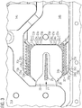
- Figure 3 shows a top view of an exemplary nozzle body 26 arranged on the heat sink fin arrangement of the base body 12 according to Figure 1 .
- the nozzle body 26 is obtained by means of die casting using an aluminum-based die casting alloy.
- the nozzle body 26 comprises an inner recess portion 28 tapering in the direction of the input fluid flow P1.
- the nozzle body 26 comprises a longitudinally extending fluid inlet 29 configured to split the input fluid flow in the direction P1 into a first output fluid flow in the direction P2' and a second output fluid flow in the direction P3'.
- the direction P2' and the direction P3' are parallel to the first longitudinal direction P2 and the second longitudinal direction P3 shown in Figure 2 .
- the nozzle body 26 is arranged on the inner base body portion 20 such that the longitudinally extending fluid inlet 29 is aligned with the symmetry axis S of the plurality of protrusions 22a to 22o and 24a to 24o.
- FIG 4 shows an exploded view of the embodiment of the fluid-based cooling element 10 fixable to a printed circuit board 100.
- the printed circuit board 100 comprises a heat generating element 102 to be cooled (e.g. a high-power microprocessor).
- the fluid-based cooling element 10 is configured to be fixed to the printed circuit board 100 by means of fixing members 40.
- the fluid-based cooling element 10 is fixable to the printed circuit board 100 such that the inner base body portion 20 is arranged above the heat generating element 102.
- the heat generating element 102 can efficiently be cooled by the fluid-based cooling element 10.
- the fluid-based cooling element 10 comprises the base body 12 comprising the plate-shaped base body portion 11 and the inner base body portion 20 integrally formed with the plate-shaped base body portion 11.
- the fluid-based cooling element 10 comprises a sealing element 30 configured to be received by the circumferential recess portion 18 formed in the upper surface of the plate-shaped base body portion 11.
- the fluid-based cooling element 10 further comprises the nozzle body 26 with the inner recess portion 28 configured to be arranged perpendicular above the inner base body portion 20 so as to be in mechanical and thermal contact with the heat sink fins formed on the upper side of the inner base body portion 20.
- the fluid-based cooling element 10 further comprises a sealing body 32 configured to be arranged on the plate-shaped base body portion 11.
- the sealing body 32 is plate-shaped and can be fixed to the plate-shaped base body portion 11 by means of a plurality of fixing elements, such as screws 34.
- the plate-shaped base body portion 11, the inner base body portion 20 and the sealing body 32 together define the fluid chamber.
- a connecting element 36 may be provided on one side of the base body 12 comprising a fluid inlet 38a and a fluid outlet 38b. By means of the fluid inlet 38a and the fluid outlet 38b, a controlled fluid flow though the fluid chamber defined within the plate-shaped base body portion 11 can be provided.
- Embodiments of the invention provide a rapid production of high performance cold plates (i.e. the fluid-based cooling element 10) using a pressure die casting of the aluminum-based alloy G-AISil2 where the complete cooling fin heat sink structure can be die casted in a single operation, without any further manufacturing process.
- Embodiments of the invention provide the advantage that the cooling fin gap size D can be as small as 1 mm or less. Contrary to the known pre-forming techniques, embodiments of the invention allow for the production of a high-density heat sink fin structure with filigrane heat sink cooling channels.
- the use of the afore-mentioned alloy G-AISil2 is preferred since it offers excellent die casting properties while maintaining a high thermal conductivity, casting yield rate and corrosion resistance.
- the employed die casting alloy is substantially copper-free ( ⁇ 0.05 %) which further improves the reliability of the cold plate 10 by avoiding galvanic corrosion.
- the following alloys can be used as well: G-AlSi7Mg, G-AISi5Mg, G-AlMg3, G-AlMg5, G-AlMg5Si or G-AlSi10Mg.
- pure aluminum since pure aluminum has a low strength and is difficult to cast, it is typically used only for special applications such as electric motor components for which a high electric and thermal conductivity is required.
- silicon (Si) as an exemplary additive in the employed aluminum alloys is advantageous since it lowers the melting point and increases the melt flow, fluidity, hardness and strength.
- embodiments of the invention provide a non-linear cooling fin array design where the angle ⁇ 3 between both halfs of the heat sink fin structure is equal to or larger than 30° and smaller than 180°.
- This inventive design lengthens the cooling channels which in turn increases the effective heat sink surface (up to 40% compared to a straight fin array structure). Further, the hydraulic performance can be improved.
- a central fluid inlet split-flow design can be used in order to increase the thermal performance of the cold plate 10 while at the same time decreasing the hydraulic restriction.
- a central inlet split-flow nozzle 26 is provided which can also be made from a die casting aluminum-based alloy. This helps to improve the cooling performance of the cold plate 10 as the nozzle 26 and the cold plate fin structure are in a mechanical and thus thermal contact.
- the nozzle 26 can also be made from another material, like plastic, albeit without additional thermal performance gains.
- embodiments of the invention also allow for a welding of a sealing lid which eliminates the need for sealing gaskets and fasteners.
- the invention also provides the advantage that due to the specific size or density of the cooling fin structure, there is substantially no danger of a heat induced deformation of the cooling fin array, especially when compared to a thinner structure made by using skiving or other material removal techniques.
Landscapes
- Engineering & Computer Science (AREA)
- Microelectronics & Electronic Packaging (AREA)
- Physics & Mathematics (AREA)
- Thermal Sciences (AREA)
- Cooling Or The Like Of Semiconductors Or Solid State Devices (AREA)
- Cooling Or The Like Of Electrical Apparatus (AREA)
Priority Applications (4)
| Application Number | Priority Date | Filing Date | Title |
|---|---|---|---|
| EP17162828.2A EP3379908B1 (de) | 2017-03-24 | 2017-03-24 | Verfahren zur herstellung eines fluidbasierten kühlelements und fluidbasiertes kühlelement |
| CN201880019920.4A CN110463368A (zh) | 2017-03-24 | 2018-03-23 | 用于制造流体基冷却元件以及流体基冷却元件 |
| PCT/EP2018/057483 WO2018172534A1 (en) | 2017-03-24 | 2018-03-23 | Method for manufacturing a fluid-based cooling element and fluid-based cooling element |
| US16/494,954 US20200015384A1 (en) | 2017-03-24 | 2018-03-23 | Method for manufacturing a fluid-based cooling element and fluid-based cooling element |
Applications Claiming Priority (1)
| Application Number | Priority Date | Filing Date | Title |
|---|---|---|---|
| EP17162828.2A EP3379908B1 (de) | 2017-03-24 | 2017-03-24 | Verfahren zur herstellung eines fluidbasierten kühlelements und fluidbasiertes kühlelement |
Publications (2)
| Publication Number | Publication Date |
|---|---|
| EP3379908A1 true EP3379908A1 (de) | 2018-09-26 |
| EP3379908B1 EP3379908B1 (de) | 2020-04-29 |
Family
ID=58605992
Family Applications (1)
| Application Number | Title | Priority Date | Filing Date |
|---|---|---|---|
| EP17162828.2A Not-in-force EP3379908B1 (de) | 2017-03-24 | 2017-03-24 | Verfahren zur herstellung eines fluidbasierten kühlelements und fluidbasiertes kühlelement |
Country Status (4)
| Country | Link |
|---|---|
| US (1) | US20200015384A1 (de) |
| EP (1) | EP3379908B1 (de) |
| CN (1) | CN110463368A (de) |
| WO (1) | WO2018172534A1 (de) |
Families Citing this family (5)
| Publication number | Priority date | Publication date | Assignee | Title |
|---|---|---|---|---|
| US11153965B1 (en) * | 2019-11-14 | 2021-10-19 | Rockwell Collins, Inc. | Integrated vapor chamber printed circuit board (PCB) assembly |
| US11785740B2 (en) * | 2020-06-26 | 2023-10-10 | Lear Corporation | High-voltage junction box coolant baffle |
| US11729944B2 (en) * | 2021-05-21 | 2023-08-15 | Quanta Computer Inc. | Cold plate with anti-clogging mechanism |
| JP7687795B2 (ja) * | 2021-09-08 | 2025-06-03 | 日本電気株式会社 | ヒートシンク |
| CN117440645A (zh) * | 2022-07-15 | 2024-01-23 | 华为技术有限公司 | 电子组件和电子设备 |
Citations (5)
| Publication number | Priority date | Publication date | Assignee | Title |
|---|---|---|---|---|
| US20050103472A1 (en) * | 2003-11-19 | 2005-05-19 | Lofland Steve J. | Cold plate |
| US20120247743A1 (en) * | 2011-04-01 | 2012-10-04 | Toyota Jidosha Kabushiki Kaisha | Heat sink, and heat sink-equipped electronic component part |
| US20140043765A1 (en) * | 2011-04-26 | 2014-02-13 | Fuji Electric Co., Ltd | Semiconductor module cooler and semiconductor module |
| US20140138063A1 (en) * | 2011-04-20 | 2014-05-22 | Nippon Soken, Inc | Cooling fin structure |
| GB2536051A (en) * | 2015-03-06 | 2016-09-07 | Hiflux Ltd | Heatsink |
Family Cites Families (3)
| Publication number | Priority date | Publication date | Assignee | Title |
|---|---|---|---|---|
| CN100546450C (zh) * | 2006-05-19 | 2009-09-30 | 国立中央大学 | 液体冷却式散热装置的散热器 |
| CN103996665B (zh) * | 2014-06-09 | 2016-08-03 | 电子科技大学 | 一种采用脉动流及波壁微通道的强化散热装置 |
| CN104159438B (zh) * | 2014-08-28 | 2017-02-08 | 电子科技大学 | 一种采用纳米工质流体及脉动流的微通道散热装置 |
-
2017
- 2017-03-24 EP EP17162828.2A patent/EP3379908B1/de not_active Not-in-force
-
2018
- 2018-03-23 US US16/494,954 patent/US20200015384A1/en not_active Abandoned
- 2018-03-23 CN CN201880019920.4A patent/CN110463368A/zh active Pending
- 2018-03-23 WO PCT/EP2018/057483 patent/WO2018172534A1/en not_active Ceased
Patent Citations (5)
| Publication number | Priority date | Publication date | Assignee | Title |
|---|---|---|---|---|
| US20050103472A1 (en) * | 2003-11-19 | 2005-05-19 | Lofland Steve J. | Cold plate |
| US20120247743A1 (en) * | 2011-04-01 | 2012-10-04 | Toyota Jidosha Kabushiki Kaisha | Heat sink, and heat sink-equipped electronic component part |
| US20140138063A1 (en) * | 2011-04-20 | 2014-05-22 | Nippon Soken, Inc | Cooling fin structure |
| US20140043765A1 (en) * | 2011-04-26 | 2014-02-13 | Fuji Electric Co., Ltd | Semiconductor module cooler and semiconductor module |
| GB2536051A (en) * | 2015-03-06 | 2016-09-07 | Hiflux Ltd | Heatsink |
Also Published As
| Publication number | Publication date |
|---|---|
| US20200015384A1 (en) | 2020-01-09 |
| WO2018172534A1 (en) | 2018-09-27 |
| EP3379908B1 (de) | 2020-04-29 |
| CN110463368A (zh) | 2019-11-15 |
Similar Documents
| Publication | Publication Date | Title |
|---|---|---|
| EP3379908B1 (de) | Verfahren zur herstellung eines fluidbasierten kühlelements und fluidbasiertes kühlelement | |
| US9245821B2 (en) | Cooling device for semiconductor module, and semiconductor module | |
| US8365409B2 (en) | Heat exchanger and method of manufacturing the same | |
| CN105308742B (zh) | 半导体组件用冷却器的制造方法、半导体组件用冷却器、半导体组件和电驱动车辆 | |
| JP5608187B2 (ja) | ヒートシンク | |
| JP4888721B2 (ja) | 板状のフィンを有する放熱器の製造方法 | |
| US6397926B1 (en) | Heat sink, method manufacturing the same and cooling apparatus using the same | |
| US8860210B2 (en) | Semiconductor device | |
| CN103107149A (zh) | 液冷式冷却装置及其制造方法 | |
| EP2944395A1 (de) | Verfahren zur herstellung einer kühlvorrichtung und wärmeableitendes element | |
| JP2013254787A (ja) | 熱交換器及びその製造方法 | |
| US20160088770A1 (en) | Heatsink equipped with plural fins whose connection methods are different | |
| CN105514064A (zh) | 散热器 | |
| JP2013219127A (ja) | 熱交換器 | |
| JP2016219571A (ja) | 液冷式冷却装置 | |
| GB2536051A (en) | Heatsink | |
| JP5316004B2 (ja) | 冷却装置 | |
| US12424512B2 (en) | Cooling system comprising a serpentine passageway | |
| JP4723661B2 (ja) | 受熱面平行フィン型扁平状放熱構造体 | |
| JP2003234443A (ja) | フィン付ヒートシンク | |
| EP3923320A1 (de) | Kühlstruktur | |
| JP6491553B2 (ja) | 放熱器の製造装置 | |
| US20250230993A1 (en) | Cooling device | |
| US20250151236A1 (en) | Heatsink design with variable effective heat transfer coefficient | |
| CN215500288U (zh) | 车辆的控制器和车辆 |
Legal Events
| Date | Code | Title | Description |
|---|---|---|---|
| PUAI | Public reference made under article 153(3) epc to a published international application that has entered the european phase |
Free format text: ORIGINAL CODE: 0009012 |
|
| STAA | Information on the status of an ep patent application or granted ep patent |
Free format text: STATUS: THE APPLICATION HAS BEEN PUBLISHED |
|
| AK | Designated contracting states |
Kind code of ref document: A1 Designated state(s): AL AT BE BG CH CY CZ DE DK EE ES FI FR GB GR HR HU IE IS IT LI LT LU LV MC MK MT NL NO PL PT RO RS SE SI SK SM TR |
|
| AX | Request for extension of the european patent |
Extension state: BA ME |
|
| TPAC | Observations filed by third parties |
Free format text: ORIGINAL CODE: EPIDOSNTIPA |
|
| STAA | Information on the status of an ep patent application or granted ep patent |
Free format text: STATUS: REQUEST FOR EXAMINATION WAS MADE |
|
| 17P | Request for examination filed |
Effective date: 20190326 |
|
| RBV | Designated contracting states (corrected) |
Designated state(s): AL AT BE BG CH CY CZ DE DK EE ES FI FR GB GR HR HU IE IS IT LI LT LU LV MC MK MT NL NO PL PT RO RS SE SI SK SM TR |
|
| GRAP | Despatch of communication of intention to grant a patent |
Free format text: ORIGINAL CODE: EPIDOSNIGR1 |
|
| STAA | Information on the status of an ep patent application or granted ep patent |
Free format text: STATUS: GRANT OF PATENT IS INTENDED |
|
| INTG | Intention to grant announced |
Effective date: 20191025 |
|
| GRAS | Grant fee paid |
Free format text: ORIGINAL CODE: EPIDOSNIGR3 |
|
| GRAA | (expected) grant |
Free format text: ORIGINAL CODE: 0009210 |
|
| STAA | Information on the status of an ep patent application or granted ep patent |
Free format text: STATUS: THE PATENT HAS BEEN GRANTED |
|
| AK | Designated contracting states |
Kind code of ref document: B1 Designated state(s): AL AT BE BG CH CY CZ DE DK EE ES FI FR GB GR HR HU IE IS IT LI LT LU LV MC MK MT NL NO PL PT RO RS SE SI SK SM TR |
|
| REG | Reference to a national code |
Ref country code: GB Ref legal event code: FG4D |
|
| REG | Reference to a national code |
Ref country code: CH Ref legal event code: EP |
|
| REG | Reference to a national code |
Ref country code: AT Ref legal event code: REF Ref document number: 1265307 Country of ref document: AT Kind code of ref document: T Effective date: 20200515 |
|
| REG | Reference to a national code |
Ref country code: DE Ref legal event code: R096 Ref document number: 602017015482 Country of ref document: DE |
|
| REG | Reference to a national code |
Ref country code: IE Ref legal event code: FG4D |
|
| REG | Reference to a national code |
Ref country code: NL Ref legal event code: MP Effective date: 20200429 |
|
| REG | Reference to a national code |
Ref country code: LT Ref legal event code: MG4D |
|
| PG25 | Lapsed in a contracting state [announced via postgrant information from national office to epo] |
Ref country code: PT Free format text: LAPSE BECAUSE OF FAILURE TO SUBMIT A TRANSLATION OF THE DESCRIPTION OR TO PAY THE FEE WITHIN THE PRESCRIBED TIME-LIMIT Effective date: 20200831 Ref country code: IS Free format text: LAPSE BECAUSE OF FAILURE TO SUBMIT A TRANSLATION OF THE DESCRIPTION OR TO PAY THE FEE WITHIN THE PRESCRIBED TIME-LIMIT Effective date: 20200829 Ref country code: GR Free format text: LAPSE BECAUSE OF FAILURE TO SUBMIT A TRANSLATION OF THE DESCRIPTION OR TO PAY THE FEE WITHIN THE PRESCRIBED TIME-LIMIT Effective date: 20200730 Ref country code: LT Free format text: LAPSE BECAUSE OF FAILURE TO SUBMIT A TRANSLATION OF THE DESCRIPTION OR TO PAY THE FEE WITHIN THE PRESCRIBED TIME-LIMIT Effective date: 20200429 Ref country code: NO Free format text: LAPSE BECAUSE OF FAILURE TO SUBMIT A TRANSLATION OF THE DESCRIPTION OR TO PAY THE FEE WITHIN THE PRESCRIBED TIME-LIMIT Effective date: 20200729 Ref country code: SE Free format text: LAPSE BECAUSE OF FAILURE TO SUBMIT A TRANSLATION OF THE DESCRIPTION OR TO PAY THE FEE WITHIN THE PRESCRIBED TIME-LIMIT Effective date: 20200429 Ref country code: FI Free format text: LAPSE BECAUSE OF FAILURE TO SUBMIT A TRANSLATION OF THE DESCRIPTION OR TO PAY THE FEE WITHIN THE PRESCRIBED TIME-LIMIT Effective date: 20200429 |
|
| REG | Reference to a national code |
Ref country code: AT Ref legal event code: MK05 Ref document number: 1265307 Country of ref document: AT Kind code of ref document: T Effective date: 20200429 |
|
| PG25 | Lapsed in a contracting state [announced via postgrant information from national office to epo] |
Ref country code: LV Free format text: LAPSE BECAUSE OF FAILURE TO SUBMIT A TRANSLATION OF THE DESCRIPTION OR TO PAY THE FEE WITHIN THE PRESCRIBED TIME-LIMIT Effective date: 20200429 Ref country code: HR Free format text: LAPSE BECAUSE OF FAILURE TO SUBMIT A TRANSLATION OF THE DESCRIPTION OR TO PAY THE FEE WITHIN THE PRESCRIBED TIME-LIMIT Effective date: 20200429 Ref country code: BG Free format text: LAPSE BECAUSE OF FAILURE TO SUBMIT A TRANSLATION OF THE DESCRIPTION OR TO PAY THE FEE WITHIN THE PRESCRIBED TIME-LIMIT Effective date: 20200729 Ref country code: RS Free format text: LAPSE BECAUSE OF FAILURE TO SUBMIT A TRANSLATION OF THE DESCRIPTION OR TO PAY THE FEE WITHIN THE PRESCRIBED TIME-LIMIT Effective date: 20200429 |
|
| PG25 | Lapsed in a contracting state [announced via postgrant information from national office to epo] |
Ref country code: AL Free format text: LAPSE BECAUSE OF FAILURE TO SUBMIT A TRANSLATION OF THE DESCRIPTION OR TO PAY THE FEE WITHIN THE PRESCRIBED TIME-LIMIT Effective date: 20200429 Ref country code: NL Free format text: LAPSE BECAUSE OF FAILURE TO SUBMIT A TRANSLATION OF THE DESCRIPTION OR TO PAY THE FEE WITHIN THE PRESCRIBED TIME-LIMIT Effective date: 20200429 |
|
| PG25 | Lapsed in a contracting state [announced via postgrant information from national office to epo] |
Ref country code: SM Free format text: LAPSE BECAUSE OF FAILURE TO SUBMIT A TRANSLATION OF THE DESCRIPTION OR TO PAY THE FEE WITHIN THE PRESCRIBED TIME-LIMIT Effective date: 20200429 Ref country code: EE Free format text: LAPSE BECAUSE OF FAILURE TO SUBMIT A TRANSLATION OF THE DESCRIPTION OR TO PAY THE FEE WITHIN THE PRESCRIBED TIME-LIMIT Effective date: 20200429 Ref country code: AT Free format text: LAPSE BECAUSE OF FAILURE TO SUBMIT A TRANSLATION OF THE DESCRIPTION OR TO PAY THE FEE WITHIN THE PRESCRIBED TIME-LIMIT Effective date: 20200429 Ref country code: ES Free format text: LAPSE BECAUSE OF FAILURE TO SUBMIT A TRANSLATION OF THE DESCRIPTION OR TO PAY THE FEE WITHIN THE PRESCRIBED TIME-LIMIT Effective date: 20200429 Ref country code: CZ Free format text: LAPSE BECAUSE OF FAILURE TO SUBMIT A TRANSLATION OF THE DESCRIPTION OR TO PAY THE FEE WITHIN THE PRESCRIBED TIME-LIMIT Effective date: 20200429 Ref country code: RO Free format text: LAPSE BECAUSE OF FAILURE TO SUBMIT A TRANSLATION OF THE DESCRIPTION OR TO PAY THE FEE WITHIN THE PRESCRIBED TIME-LIMIT Effective date: 20200429 Ref country code: IT Free format text: LAPSE BECAUSE OF FAILURE TO SUBMIT A TRANSLATION OF THE DESCRIPTION OR TO PAY THE FEE WITHIN THE PRESCRIBED TIME-LIMIT Effective date: 20200429 Ref country code: DK Free format text: LAPSE BECAUSE OF FAILURE TO SUBMIT A TRANSLATION OF THE DESCRIPTION OR TO PAY THE FEE WITHIN THE PRESCRIBED TIME-LIMIT Effective date: 20200429 |
|
| REG | Reference to a national code |
Ref country code: DE Ref legal event code: R097 Ref document number: 602017015482 Country of ref document: DE |
|
| PG25 | Lapsed in a contracting state [announced via postgrant information from national office to epo] |
Ref country code: SK Free format text: LAPSE BECAUSE OF FAILURE TO SUBMIT A TRANSLATION OF THE DESCRIPTION OR TO PAY THE FEE WITHIN THE PRESCRIBED TIME-LIMIT Effective date: 20200429 Ref country code: PL Free format text: LAPSE BECAUSE OF FAILURE TO SUBMIT A TRANSLATION OF THE DESCRIPTION OR TO PAY THE FEE WITHIN THE PRESCRIBED TIME-LIMIT Effective date: 20200429 |
|
| PLBE | No opposition filed within time limit |
Free format text: ORIGINAL CODE: 0009261 |
|
| STAA | Information on the status of an ep patent application or granted ep patent |
Free format text: STATUS: NO OPPOSITION FILED WITHIN TIME LIMIT |
|
| 26N | No opposition filed |
Effective date: 20210201 |
|
| PG25 | Lapsed in a contracting state [announced via postgrant information from national office to epo] |
Ref country code: SI Free format text: LAPSE BECAUSE OF FAILURE TO SUBMIT A TRANSLATION OF THE DESCRIPTION OR TO PAY THE FEE WITHIN THE PRESCRIBED TIME-LIMIT Effective date: 20200429 |
|
| PGFP | Annual fee paid to national office [announced via postgrant information from national office to epo] |
Ref country code: GB Payment date: 20210324 Year of fee payment: 5 |
|
| PGFP | Annual fee paid to national office [announced via postgrant information from national office to epo] |
Ref country code: DE Payment date: 20210427 Year of fee payment: 5 |
|
| PG25 | Lapsed in a contracting state [announced via postgrant information from national office to epo] |
Ref country code: MC Free format text: LAPSE BECAUSE OF FAILURE TO SUBMIT A TRANSLATION OF THE DESCRIPTION OR TO PAY THE FEE WITHIN THE PRESCRIBED TIME-LIMIT Effective date: 20200429 |
|
| REG | Reference to a national code |
Ref country code: CH Ref legal event code: PL |
|
| REG | Reference to a national code |
Ref country code: BE Ref legal event code: MM Effective date: 20210331 |
|
| PG25 | Lapsed in a contracting state [announced via postgrant information from national office to epo] |
Ref country code: CH Free format text: LAPSE BECAUSE OF NON-PAYMENT OF DUE FEES Effective date: 20210331 Ref country code: LU Free format text: LAPSE BECAUSE OF NON-PAYMENT OF DUE FEES Effective date: 20210324 Ref country code: LI Free format text: LAPSE BECAUSE OF NON-PAYMENT OF DUE FEES Effective date: 20210331 Ref country code: IE Free format text: LAPSE BECAUSE OF NON-PAYMENT OF DUE FEES Effective date: 20210324 Ref country code: FR Free format text: LAPSE BECAUSE OF NON-PAYMENT OF DUE FEES Effective date: 20210331 |
|
| PG25 | Lapsed in a contracting state [announced via postgrant information from national office to epo] |
Ref country code: BE Free format text: LAPSE BECAUSE OF NON-PAYMENT OF DUE FEES Effective date: 20210331 |
|
| REG | Reference to a national code |
Ref country code: DE Ref legal event code: R119 Ref document number: 602017015482 Country of ref document: DE |
|
| GBPC | Gb: european patent ceased through non-payment of renewal fee |
Effective date: 20220324 |
|
| PG25 | Lapsed in a contracting state [announced via postgrant information from national office to epo] |
Ref country code: GB Free format text: LAPSE BECAUSE OF NON-PAYMENT OF DUE FEES Effective date: 20220324 Ref country code: DE Free format text: LAPSE BECAUSE OF NON-PAYMENT OF DUE FEES Effective date: 20221001 |
|
| PG25 | Lapsed in a contracting state [announced via postgrant information from national office to epo] |
Ref country code: CY Free format text: LAPSE BECAUSE OF FAILURE TO SUBMIT A TRANSLATION OF THE DESCRIPTION OR TO PAY THE FEE WITHIN THE PRESCRIBED TIME-LIMIT Effective date: 20200429 |
|
| PG25 | Lapsed in a contracting state [announced via postgrant information from national office to epo] |
Ref country code: HU Free format text: LAPSE BECAUSE OF FAILURE TO SUBMIT A TRANSLATION OF THE DESCRIPTION OR TO PAY THE FEE WITHIN THE PRESCRIBED TIME-LIMIT; INVALID AB INITIO Effective date: 20170324 |
|
| PG25 | Lapsed in a contracting state [announced via postgrant information from national office to epo] |
Ref country code: MK Free format text: LAPSE BECAUSE OF FAILURE TO SUBMIT A TRANSLATION OF THE DESCRIPTION OR TO PAY THE FEE WITHIN THE PRESCRIBED TIME-LIMIT Effective date: 20200429 |
|
| PG25 | Lapsed in a contracting state [announced via postgrant information from national office to epo] |
Ref country code: TR Free format text: LAPSE BECAUSE OF FAILURE TO SUBMIT A TRANSLATION OF THE DESCRIPTION OR TO PAY THE FEE WITHIN THE PRESCRIBED TIME-LIMIT Effective date: 20200429 |
|
| PG25 | Lapsed in a contracting state [announced via postgrant information from national office to epo] |
Ref country code: MT Free format text: LAPSE BECAUSE OF FAILURE TO SUBMIT A TRANSLATION OF THE DESCRIPTION OR TO PAY THE FEE WITHIN THE PRESCRIBED TIME-LIMIT Effective date: 20200429 |