EP3379552B1 - Betätigungselement zur bewegung eines beweglichen bauelements - Google Patents
Betätigungselement zur bewegung eines beweglichen bauelements Download PDFInfo
- Publication number
- EP3379552B1 EP3379552B1 EP17162441.4A EP17162441A EP3379552B1 EP 3379552 B1 EP3379552 B1 EP 3379552B1 EP 17162441 A EP17162441 A EP 17162441A EP 3379552 B1 EP3379552 B1 EP 3379552B1
- Authority
- EP
- European Patent Office
- Prior art keywords
- actuating element
- actuating
- threaded body
- component
- contact
- Prior art date
- Legal status (The legal status is an assumption and is not a legal conclusion. Google has not performed a legal analysis and makes no representation as to the accuracy of the status listed.)
- Active
Links
Images


Classifications
-
- H—ELECTRICITY
- H01—ELECTRIC ELEMENTS
- H01H—ELECTRIC SWITCHES; RELAYS; SELECTORS; EMERGENCY PROTECTIVE DEVICES
- H01H3/00—Mechanisms for operating contacts
- H01H3/32—Driving mechanisms, i.e. for transmitting driving force to the contacts
- H01H3/42—Driving mechanisms, i.e. for transmitting driving force to the contacts using cam or eccentric
-
- E—FIXED CONSTRUCTIONS
- E05—LOCKS; KEYS; WINDOW OR DOOR FITTINGS; SAFES
- E05B—LOCKS; ACCESSORIES THEREFOR; HANDCUFFS
- E05B15/00—Other details of locks; Parts for engagement by bolts of fastening devices
- E05B15/04—Spring arrangements in locks
-
- E—FIXED CONSTRUCTIONS
- E05—LOCKS; KEYS; WINDOW OR DOOR FITTINGS; SAFES
- E05B—LOCKS; ACCESSORIES THEREFOR; HANDCUFFS
- E05B17/00—Accessories in connection with locks
- E05B17/22—Means for operating or controlling lock or fastening device accessories, i.e. other than the fastening members, e.g. switches, indicators
-
- E—FIXED CONSTRUCTIONS
- E05—LOCKS; KEYS; WINDOW OR DOOR FITTINGS; SAFES
- E05B—LOCKS; ACCESSORIES THEREFOR; HANDCUFFS
- E05B63/00—Locks or fastenings with special structural characteristics
- E05B63/0056—Locks with adjustable or exchangeable lock parts
-
- H—ELECTRICITY
- H01—ELECTRIC ELEMENTS
- H01H—ELECTRIC SWITCHES; RELAYS; SELECTORS; EMERGENCY PROTECTIVE DEVICES
- H01H13/00—Switches having rectilinearly-movable operating part or parts adapted for pushing or pulling in one direction only, e.g. push-button switch
- H01H13/02—Details
- H01H13/12—Movable parts; Contacts mounted thereon
- H01H13/14—Operating parts, e.g. push-button
- H01H13/18—Operating parts, e.g. push-button adapted for actuation at a limit or other predetermined position in the path of a body, the relative movement of switch and body being primarily for a purpose other than the actuation of the switch, e.g. door switch, limit switch, floor-levelling switch of a lift
- H01H13/186—Operating parts, e.g. push-button adapted for actuation at a limit or other predetermined position in the path of a body, the relative movement of switch and body being primarily for a purpose other than the actuation of the switch, e.g. door switch, limit switch, floor-levelling switch of a lift wherein the pushbutton is rectilinearly actuated by a lever pivoting on the housing of the switch
-
- H—ELECTRICITY
- H01—ELECTRIC ELEMENTS
- H01H—ELECTRIC SWITCHES; RELAYS; SELECTORS; EMERGENCY PROTECTIVE DEVICES
- H01H3/00—Mechanisms for operating contacts
- H01H3/02—Operating parts, i.e. for operating driving mechanism by a mechanical force external to the switch
- H01H3/16—Operating parts, i.e. for operating driving mechanism by a mechanical force external to the switch adapted for actuation at a limit or other predetermined position in the path of a body, the relative movement of switch and body being primarily for a purpose other than the actuation of the switch, e.g. for a door switch, a limit switch, a floor-levelling switch of a lift
- H01H3/161—Operating parts, i.e. for operating driving mechanism by a mechanical force external to the switch adapted for actuation at a limit or other predetermined position in the path of a body, the relative movement of switch and body being primarily for a purpose other than the actuation of the switch, e.g. for a door switch, a limit switch, a floor-levelling switch of a lift for actuation by moving a closing member, e.g. door, cover or lid
- H01H3/163—Operating parts, i.e. for operating driving mechanism by a mechanical force external to the switch adapted for actuation at a limit or other predetermined position in the path of a body, the relative movement of switch and body being primarily for a purpose other than the actuation of the switch, e.g. for a door switch, a limit switch, a floor-levelling switch of a lift for actuation by moving a closing member, e.g. door, cover or lid associated with locking or manipulating means of the closing member
-
- H—ELECTRICITY
- H01—ELECTRIC ELEMENTS
- H01H—ELECTRIC SWITCHES; RELAYS; SELECTORS; EMERGENCY PROTECTIVE DEVICES
- H01H3/00—Mechanisms for operating contacts
- H01H3/22—Power arrangements internal to the switch for operating the driving mechanism
- H01H3/30—Power arrangements internal to the switch for operating the driving mechanism using spring motor
- H01H3/3042—Power arrangements internal to the switch for operating the driving mechanism using spring motor using a torsion spring
-
- E—FIXED CONSTRUCTIONS
- E05—LOCKS; KEYS; WINDOW OR DOOR FITTINGS; SAFES
- E05B—LOCKS; ACCESSORIES THEREFOR; HANDCUFFS
- E05B63/00—Locks or fastenings with special structural characteristics
- E05B63/18—Locks or fastenings with special structural characteristics with arrangements independent of the locking mechanism for retaining the bolt or latch in the retracted position
- E05B63/20—Locks or fastenings with special structural characteristics with arrangements independent of the locking mechanism for retaining the bolt or latch in the retracted position released automatically when the wing is closed
Definitions
- the invention relates to an actuating element according to claim 1. Furthermore, the invention relates to a system according to claim 13.
- Switches for position detection of movable components are basically known from the prior art.
- microswitches can be used as such switches.
- a microswitch e.g. B. in door locks
- an actuating element is required, with its relative movement to a switching flag of the microswitch, a switching signal is generated.
- the more exact the size of the microswitch decreases (miniaturization) the greater the demands placed on the positioning accuracy of the actuating element.
- the adjustability of the switching position of the actuating element is imperative.
- the distance between the actuating element and the microswitch can be functionally critical.
- the actuating element In the case of known actuating elements, the actuating element is displaced until the correct switching point is reached at the switch in order to set the switching point. The actuating element is then fixed in this position. A later readjustment is difficult, sometimes impossible.
- the position of the microswitch In the case of rigid, non-adjustable actuating elements, the position of the microswitch can in turn be changed, but this is not possible in the case of microswitches fixed to the circuit board. In this case, the switch flags are adjusted.
- Some actuating elements are designed to be dimensionally elastic in order to enable tolerance compensation in the switching position of the actuating element, as a result of which the adjustability of the switching position is no longer necessary. However, it is disadvantageous that the microswitch can be damaged by excessive deformation of the actuating element.
- a movable component to which the actuating element is attached is referred to as a movable component.
- the movable element that is to be moved by the movable component with the aid of the actuating element is referred to as a movable component.
- An actuator for actuating a switch flag of a switch is from the DE-A-2815888 known.
- Features and details that are described in connection with the actuating element according to the invention apply, of course, also in connection with the system according to the invention and vice versa, so that with respect to the disclosure of the individual aspects of the invention, reference is always made or can be made to one another.
- the object is also achieved by a system with an actuating element according to the invention, in particular with an actuating element according to one of claims 1 to 12.
- a lock with a system according to the invention is also placed under protection.
- the lock according to the invention can comprise an actuating element according to the invention, in particular an actuating element according to one of claims 1 to 12, and / or an inventive system, in particular with a system according to one of claims 13 to 15.
- an actuating element for moving a movable component in particular a switching flag of a switch, which is formed with a threaded body for fastening the actuating element to a movable component and a contact element for moving the movable component, the threaded body being designed for adjusting the contact element ,
- the switch can be designed as a microswitch.
- the switch can be used to detect the position of the movable component.
- the movable component can move a movable component.
- the movable component and the movable component z. B. be part of a transmission.
- a point at which the movable component contacts the movable component can be adjustable by the adjustment. Due to the adjustment, the position at which the movable component contacts the movable component can be changed, in particular shifted, in its spatial position. The spatial extent of the point at which the movable component contacts the movable component preferably remains unchanged.
- the idea of the invention is to design the actuating element with a threaded body and at least one, in particular terminal, contact element, the contact element projecting beyond the threaded body of the actuating element.
- the threaded body can be formed from a spring wire or from a monolithic body, for example made of plastic, with an external thread.
- the threaded body can serve as a screw insert for fastening the actuating element, for example in a threaded receptacle, to the movable component.
- the threaded body can thus be screwed to the movable component, the position of which can be detected.
- the contact element can extend from the threaded body axially or at the end and preferably eccentrically to the threaded body.
- the contact element is in the screwed-in state from one end of the threaded body.
- the contact element lies in the actuation area of a switching flag of a microswitch.
- the adjustment can e.g. B. take place in order to ensure a simple and precise setting of the switching point or switching range on the switch, for example on the microswitch. It is also advantageous that a subsequent readjustment of the switching point or switching range on the switch is easily possible at any time. It is also possible to create an exact translation or a specific lever by adjusting.
- the threaded body can also advantageously have a pretension in an axial and / or radial direction in order to secure the actuating element in the threaded receptacle on the movable component.
- the threaded body can have a self-locking in order to hold the actuating element in the set position with respect to the switch.
- the actuating element according to the invention is a simple, robust component and has a long service life. This can be ensured in particular by the elastic properties of the contact element.
- the switch can remain in operation for a long time without problems.
- the actuating element can be formed from a spring wire.
- a screw insert for example for threading, can thus be provided on the movable component with simple means and from inexpensive materials.
- the Spring wire can form the threaded body through windings and the contact element through a protruding end, which can extend in an axial direction of the threaded body beyond the threaded part of the spring wire.
- the turns in the thread body can correspond to a counter contour in the thread receptacle.
- Such an actuating element can simply be screwed to the movable component.
- the outer diameter of the threaded body can also be selected so that it is oversized compared to the thread holder.
- the pitch of the turns can be selected to be smaller or greater than the pitch of the turns in the thread receptacle. Due to the radial and / or axial flexibility of the wound thread body, its turns can nestle against the thread grooves of the thread receptacle when screwed in. A spring-elastic pretension can thus be provided in the threaded body of the actuating element in order to achieve self-locking of the screw insert in the set position on the movable component by means of static friction. This allows the set position of the contact element to be permanently secured. A subsequent securing of the set position of the contact element or fixing of the contact element is advantageously no longer necessary.
- the actuating element can be formed in one piece, in particular monolithically. The manufacture, the fastening and the handling of the actuating element can thus be simplified.
- a web running transverse to an axis of rotation of the threaded body can be provided as an assembly aid for attaching the threaded body to the movable component.
- the transverse web has the advantage that a user or a fitter can comfortably grasp this web in order to screw the threaded body into the threaded receptacle on the movable component.
- the thread receptacle can be designed as a through opening. This can make it easier to grip the web.
- the web can be locked in a corresponding contour in the thread receptacle.
- the latching can, for. B. may be provided on a bottom of the thread receiving means.
- the thread receptacle is designed as a blind hole to secure the set position of the contact element.
- the contact element is designed to be resilient.
- the contact element can yield elastically during the movement of the movable component. This can prevent breakage.
- the web can be formed between the threaded body and the contact element.
- the contact element can thus in particular connect to the web.
- the threaded body is located between the contact element and the web.
- the wire of the threaded body at one end of the threaded body into the wire of the web and the wire of the threaded body at the other end of the threaded body into the wire of the contact element.
- the contact element extends partially into the threaded body.
- the contact element can be passed through from one end to another end of the threaded body in the axial direction of the threaded body and can extend over the threaded body at the other end.
- the contact element may have been handled accordingly. The advantage can thus be achieved that the contact element can be made longer in order to allow a particularly flexible cushioning of the contact element to protect the actuating element in addition to a precise adjustment of the position.
- a predetermined breaking point can be provided between the threaded body and the web.
- the web can be formed at one end and the contact element at another end of the threaded body, wherein the threaded receptacle can be designed as a through hole with an internal thread.
- the web can be separated, for example broken off, after the threaded body has been screwed into the movable component, so that it no longer stands in the way after the actuating element has been fastened to the movable component, and in order to possibly carry out a connecting screw through the threaded body to the movable component can.
- the contact element can be aligned axially and / or eccentrically to the threaded body.
- the contact element aligned axially to the threaded body can advantageously protrude from the threaded body in order to contact the movable component, in particular in order to get into the switching area of the switch.
- the advantage of a contact element aligned eccentrically to the threaded body is that its relative position to the movable component, in particular to the switch lug of the switch, can be made possible by simply rotating the threaded body in the threaded receptacle on the movable component.
- the contact element can have a contact area for moving the movable component.
- the contact element with the contact area touches the switch during the actuation process. Through the contact area z. B. a switch flag of the switch can be moved.
- the contact element can be formed in a straight line.
- the contact area can be formed in a straight line.
- the contact area is preferably formed laterally.
- the contact area is provided deviating from an end of the contact element facing away from the threaded body.
- the contact area can be arranged outside a tip of the contact element. In the event that the contact element yields elastically when the movable component moves, the contact element can be elastically bent laterally.
- the contact area is preferably not perpendicular to the axis of rotation of the threaded body.
- z. B. include a straight line through the contact area and the axis of rotation an angle between 0 ° and 20 °, preferably between 0 ° and 10 °, particularly preferably between 0 ° and 5 °.
- the contact area and the axis of rotation are particularly preferably aligned parallel to one another. This makes z. B. an adjustment of the actuating element possible without reducing the contact with the movable component, in particular with the switching flag.
- the actuating element is preferably provided to move the movable component, in particular to actuate the switch, by a lateral movement.
- the actuating element does not move in the direction of the axis of rotation for moving the movable component.
- a movement of the actuating element for moving the movable component, in particular for actuating the switch, can take place in deviation from the direction of the axis of rotation.
- the direction of movement of the actuating element for moving the movable component is particularly preferably orthogonal to the axis of rotation.
- the The course of movement of the actuating element can be linear or curved. In the first case, the movable component in particular moves linearly with the actuating element, in the second case the movable component is pivoted.
- the switch in particular the switching flag, has a switching area which the contact element touches or comes closest to when the switch is actuated. Provision can be made for the spatial position of the switching area to be changed, in particular shifted, by adjusting the actuating element. A changed switching position of the actuating element can therefore result in a changed switching range of the switch.
- the spatial size of the switching region preferably remains unchanged when the contact element is adjusted.
- the threaded body can be designed such that an axial and / or radial internal prestress can be built up in the threaded body in the attached state on the movable component.
- a radial internal preload in the threaded body can be set by the choice of the outer diameter of the threaded body, which can have an oversize compared to the inner diameter of the threaded receptacle on the movable component.
- An axial internal prestress in the threaded body can be set by the choice of the pitch of the turns of the threaded body, which can differ from the pitch of the turns in the threaded receptacle.
- a self-locking of the actuating element in the thread holder on the movable component can be achieved by elastic deformation of the threaded body in the thread holder.
- the advantage can thus be achieved that the set switching position of the contact element with respect to the contact lug on the switch can be reliably secured without a separate securing of the contact element.
- the windings in the threaded body can bear against one another in such a way that a pre-tension can be realized in the threaded body before screwing into the threaded receptacle.
- the threaded body can have a surface structure in order to secure the threaded body on the movable component in the fastened state.
- the surface structure can be designed as a roughened and / or structured surface on the threaded body.
- the threaded body can be firmly attached to the threaded receptacle, in particular by an adhesive.
- an adhesive for example, a varnish can be applied to the threaded body, which contains microcapsules with adhesive when applied. The microcapsules can burst in the thread holder and release the adhesive.
- the thread body can be fixed to the thread receptacle with the aid of the adhesive from the microcapsules. As a result, the threaded body can be fastened particularly evenly in the thread receptacle.
- the actuating element in the context of the invention, it is also possible for the actuating element to be formed from an electrically conductive material.
- the actuating element can serve as an electrical connection for the transmission of electrical energy and / or as equipotential bonding.
- An electrical connection between the movable component and the movable component can be made possible in a simple manner, at least when the movable component is moved.
- the actuating element can have an electrically insulating casing.
- An electrically insulating sheathing can be advantageous in order to be able to grip the actuating element safely during assembly and to protect the surrounding components from unwanted current transmission during operation of the actuating element.
- the actuating element can be formed from a dielectric material.
- Such an actuating element can be advantageous for mechanically actuated switches, for example pressure switches.
- the actuating element can be formed from a temperature-dependent shape memory material.
- Such an actuating element can advantageously not only transmit elastic deformation, but also forces. It may be possible that the actuator can be heated and eventually deformed by the application of electricity.
- the actuating element can be formed from a thermally conductive material. This has the advantage that the actuating element can be used to generate a thermal bridge between two components.
- the actuating element can be formed from a hollow wire, wherein in particular the actuating element can be designed to receive a medium.
- a tubular channel can thus be formed in the actuating element in order to be able to transfer liquid and / or gaseous media between two components.
- the object according to the invention is achieved by a system, in particular for a door lock, according to claim 13.
- the door lock can in particular be a self-locking panic lock.
- the system is designed with a stationary component, at least one movable component, at least one movable component, in particular the switching flag of a switch, an actuating element for moving the movable component being provided, which is provided with a threaded body for fastening the actuating element in a threaded receptacle on movable component and a contact element for moving the movable component.
- the movable component can be a linearly displaceable component. In particular, however, it can be provided that the movable component is a pivotable component.
- the movable component is z. B. pivoted to move the movable component.
- a first movable component can be a trap, in particular an auxiliary trap, and / or a second movable component can be a nut, wherein in particular the actuating element can be designed as described above.
- the stationary component can be a fixed housing and / or a faceplate.
- the actuating element according to the invention can thus be used for function monitoring of the door lock.
- the actuating element according to the invention is advantageously suitable for detecting the position of a linearly displaceable latch, a linearly displaceable auxiliary latch, and for detecting the position of a rotatable nut, for example in comparison to the stationary component.
- the actuating element according to the invention can advantageously be used universally. Conceivable uses for the actuating element according to the invention are in all mechatronic products in which, due to lack of space, the adjustability of microswitches with the known solutions is only possible with considerable effort, for. B. TV, matrix, T ⁇ FF, etc. With the free-form terminal element there are diverse applications and uses of the actuating element, for example.
- the actuating element according to the invention is advantageous in various locks, including: motorized panic lock, mechanically actuated panic lock with electrical contacts, mechanically actuated panic lock with an electrical connection function, mechanically actuated lock with electrical connection function.
- the system according to the invention can also be used in lock components on single and double-leaf doors, on full-leaf doors and profile doors with different backset dimensions and faceplate designs.
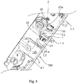
- Figure 1 shows an actuating element 10 according to the invention for a switch 21, 22, in particular for a microswitch 21, 22, which is subsequently in the Figures 2a and 2b will be shown.
- the switch 21, 22 is used for position detection of a movable component 1, 2.
- Die Figure 1 also shows the movable component 1, 2, in which a threaded receptacle 1a, 2a is formed for the actuating element 10.
- the actuating element 10 is formed with a threaded body 11 for screwing the actuating element 10 into the threaded receptacle 1a, 2a on the movable component 1, 2 and a contact element 12 for actuating the switch 21, 22.
- the contact element 12 comes into contact with a switch lug 21a, 22a of the switch 21, 22.
- the precise positioning of the contact element 12 for actuating the switch 21, 22 is functionally essential.
- the threaded body 11 is designed to change the switching position of the contact element 12 with respect to the position of the contact element 12 by rotating the threaded body 11 in the thread receptacle 1a, 2a Switch lug 21a, 22a to be set precisely, ie in order to adjust the contact element 12 in an adjustment direction J.
- the direction of rotation and the direction of adjustment are below in the Figure 2b shown.
- the Figure 2a shows a microswitch 21, 22, which has a switching flag 21a, 22a.
- the microswitch 21, 22 can be actuated, for example, with the aid of a conventional actuating element 10 'when the actuating element 10' is moved downwards relative to the switching flag 21a, 22a.
- known actuating elements 10 ' the actuating element 10' is shifted closer to the switching lug 21a, 22a until the actuating element 10 'can touch the switching lug 21a, 22a while driving past in order to set the switching point x.
- the actuating element 10 ' is then fixed in this position on the movable component 1, 2. Such positioning of the actuator 10 'is difficult and inaccurate. In addition, a later readjustment of the actuating element 10 'is also difficult if not impossible.
- the Figure 2b shows the thread holder 1a, 2a on the movable component 1, 2 for the actuating element 10 according to the invention in a sectional view.
- the switch 21, 22 is positioned above the threaded receptacle 1a, 2a, which has a distance x between the switching flag 21a, 22a and a corresponding contact 21.4, 22.4 on the switch 21, 22. By closing this distance x, the switches 21, 22 can be actuated or closed. In microswitches 21, 22, this distance x is very small and is, for example, less than 3 mm.
- the actuating element 10 according to the invention can be set very precisely. When the threaded body 11 is rotated in the direction of rotation D, the switching position of the contact element 12 on the switching lug 21a, 22a can be set precisely in the adjustment direction J, so that this distance x can be closed reliably.
- the Figure 2c shows the actuating element 10 according to the invention, which overcomes the disadvantages known from the prior art.
- the Figure 2c furthermore shows that the contact element 12 is aligned axially and eccentrically to the threaded body 11, so that the contact element 12 can reach the switching area x of the switch 21, 22 in the adjustment direction J.
- a subsequent readjustment of the switching point x on the switch 21, 22 is advantageously possible at any time in the sense of the invention, the switching point x in the Figure 2b is shown.
- the actuating element 10 can be formed from a spring wire and can be screwed in as a screw insert in the threaded receptacle 1a, 2a on the movable component 1, 2, the threaded receptacle 1a, 2a in the Figure 1 is shown.
- the spring wire forms the threaded body 11 by means of windings and the contact element 12 by a protruding end which extends in an axial direction of the threaded body 11 beyond the threaded part. It is conceivable that the spring wire can have a diameter of approximately 0.4 mm. Then a slope h2 between two adjacent turns can be approximately 0.8 mm.
- the actuating element 10 can be made from a monolithic body with an external thread.
- the windings in the threaded body 11 can correspond to a counter-contour in the threaded receptacle 1a, 2a, which has corresponding grooves for the turns of the threaded body 11.
- the outer diameter d2 of the threaded body 11 can also have an oversize compared to an inner diameter d1 of the grooves in the threaded receptacle 1a, 2a, as a result of which the turns of the threaded body 11 can nestle into the corresponding grooves in the threaded receptacle 1a, 2a.
- the pitch h2 between the turns can be selected to be larger or smaller than the pitch h1 of the furrows in the thread receptacle 1a, 2a.
- Self-locking of the actuating element 10 in the set switching position of the contact element 12 can thus be made possible.
- This The effect is in interaction with the dimensions d1, h1 of the thread holder 1a, 2b in detail in the Figure 6a shown.
- a resilient preload V can thus be set in the threaded body 11 of the actuating element 10.
- the windings in the threaded body 11 can bear against one another in such a way that a pre-tension V can be realized in the threaded body 11 before screwing into the threaded receptacle 1a, 2a.
- the set switching position of the contact element 12 Due to the self-locking of the actuating element 10 in the set position on the movable component 1, 2, the set switching position of the contact element 12 can be permanently secured. Subsequent fixing of the set switching position of the contact element 12, as is the case, for example, in the conventional actuating element 10 ' Figure 2a is necessary, is no longer necessary according to the invention.
- the actuator 10 according to the Figure 2c is also formed in one piece, which can facilitate its manufacture, attachment and handling.
- a web 13 extending transversely to an axis of rotation of the threaded body 11 can be provided on the threaded body 11 as an assembly aid for attaching the threaded body 11 to the movable component 1, 2.
- a user or a mechanic can comfortably grasp this web 13 in order to screw the threaded body 11 into the threaded receptacle 1a, 2a.
- the contact element 12 can be formed at one end and the web 13 at another end of the threaded body 11.
- the web 13 can be detachable from the threaded body 11 by a predetermined breaking point 13.1, for example after the actuating element 10 has been mounted on the movable component 1, 2. It is also conceivable that a locking screw, not shown, can be screwed into the threaded body 11 in order to to secure the actuating element 10 as an additional protection against rotation on the movable component 1, 2. Alternatively, the web 13 can be unwound from one end of the threaded body 11 and pass continuously into the contact element 12, as shown in FIGS Figures 3 to 5c is shown below. Such a web 13 remains on the actuating element 10 during operation.
- the web 13 can also serve as a locking element, which is in a corresponding locking guide on the floor of the threaded receptacle 1a, 2a can latch in order to reliably hold the set position of the contact element 12 during operation of the actuating element 10.
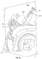
- the Figure 3 shows a system 100 according to the invention for a lock 101, for example for a self-locking panic lock 101.
- the actuating element 10 according to the invention is used therein for position detection of at least one auxiliary latch 1.1 and one latch 2.1.
- the system 100 has a stationary component 3, for example in the form of a cuff 3, with respect to which the position detection of the auxiliary trap 1.1 and the trap 2.1 takes place.
- a stationary component 3 any fixed part of the panic lock 101 can also be understood, such as. B. a housing or a housing part.
- Microswitches 21, 22 are used for position detection.
- the microswitches 21, 22 each have a switching flag 21a, 22a, which is actuated by the contact element 12 when the actuating element 10 drives past.
- the first actuating element 10 according to the invention is attached to the movable component 1 of the auxiliary latch 1.1, which is moved linearly.
- the second actuating element 10 according to the invention is fastened to a rotatable nut 2.
- the panic lock 101 has a locking cylinder 4, it also being conceivable that a third actuating element 10 according to the invention can be provided for position detection of the locking cylinder 4.
- the panic lock 101 is shown in a state in which the panic lock 101 is unlocked, a bolt 4.1 is inserted into a lock housing behind the faceplate 3, a corresponding door, not shown, is open and the nut 2 is in an actuated or tightened position located.
- the Figures 4a and 4b show in an enlarged view the area from the Figure 3 around the first movable component 1, which is connected to the auxiliary trap 1.1, from above and from below.
- a plateau 1.3 is provided on the first movable component 1, which is fastened to the movable component 1 with the aid of a bolt 1.2.
- the plateau 1.3 moves with the movable component 1.
- a thread holder 1a is provided for the threaded body 11 of the first actuating element 10.
- the first Microswitch 21 is attached to a circuit board (not shown) with the help of contacts 21.1, 21.2, 21.3.
- the extended position of the auxiliary latch 1.1 is detected, the terminal contact element 12 abutting the switching lug 21a and thus actuating the first microswitch 21.
- the auxiliary latch 1.1 is pressed back into the lock housing behind the faceplate 3 by the door frame.
- the actuating element 10 moves back with the first movable component 1 and releases the switching lug 21a of the switch 21.
- the switch 21 is thus opened, whereby a retracted position of the auxiliary latch 1.1 can be detected.
- the auxiliary latch 1.1 moves out of a corresponding opening in the faceplate 3 out of the lock housing. In this position, the switch 21 is operated again.
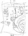
- the Figures 5a and 5b show in an enlarged view the area from the Figure 3 around the second movable component 2 in the form of a nut 2 each from above and from below.
- a thread receptacle 2a for the threaded body 11 of the second actuating element 10 is provided in the nut 2.
- the second microswitch 22 is fastened to a circuit board (not shown) with the aid of the contacts 22.1, 22.2, 22.3.
- the nut 2 is tightened in the shown state of the panic lock 101, in which the panic lock 101 is unlocked.
- the terminal contact element 12 is located at a distance from the switching lug 22a, as a result of which the second microswitch 22 is opened.
- the nut 2 is pivoted clockwise, as a result of which the contact element 12 again comes into the switching region x on the switching lug 22a in order to actuate the second microswitch 22. A rest position of the nut 2 can thus be detected.
- the Figure 5c essentially shows the area from the Figure 5a , wherein the actuating element 10 according to the invention is removed from the thread holder 2a on the nut 2. It can be seen that the actuating element 10 has a threaded body 11 with a developed transverse web 13 and a subsequent one, which runs through the threaded body 11 and out of which Threaded body 11 has extending contact element 12. In the exemplary embodiment of the invention shown, the web 13 is located between the threaded body 11 and the contact element 12. Thus, the contact element 12 can have a longer actuating arm. Alternatively, however, it is conceivable that the transverse web 13 and the contact element 12 can be unwound at different ends of the threaded body 11, as is shown, for example, in FIG Figure 1 is shown.
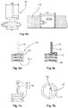
- the Figure 6a shows again in detail how an internal preload V in the threaded body 11 can be set, namely by an excess of the outer diameter d2 of the threaded body 11 with respect to the inner diameter d1 in the grooves in the thread receptacle 1a, 2a on the movable component 1, 2, or by a deviation of the slope d2 between the turns of the threaded body 11 from the slope d1 of the turns in the thread receptacle 1a, 2a.
- the self-locking of the actuator 10 can be realized in the set position.
- the threaded body 11 can have a surface structure 11.1 in order to secure the threaded body 11 on the movable component 1, 2 by static friction in the fastened state. It is conceivable that the surface structure 11.1 can be formed as a roughened and / or structured surface on the threaded body 11.
- the actuating element 10 can be formed from an electrically conductive material, for example to enable an electrical connection between the switch 21, 22 and the movable component 1, 2. It is conceivable that the actuating element 10 can have an electrically insulating casing 15, as is shown in FIG Figure 6c is shown. The electrically insulating sheath 15 can prevent unwanted current transmission from the actuating element 10. Alternatively, however, it is also conceivable that the actuating element 10 can be formed from a non-conductive material.
- an optical and / or magnetic sensor element 14 for interacting with an optical and / or magnetic sensor can be attached to the contact element 12 as an alternative switch 21, 22.
- the actuating element 10 can be formed from a hollow wire, wherein a tubular channel 16 can be formed in the actuating element 10 in order to be able to transfer liquid and / or gaseous media between two components.
- the embodiment of the invention is not limited to the exemplary embodiments of the invention described above. Rather, a large number of variants are conceivable in which form and from which materials the actuating element 10 can be formed. Materials such as a temperature-dependent shape memory material and / or a thermally conductive material etc. are conceivable.
- the actuating element 10 can be used in all mechatronic, optical and / or magnetic systems with movable components for their position detection.
Landscapes
- Engineering & Computer Science (AREA)
- Computer Security & Cryptography (AREA)
- Structural Engineering (AREA)
- Push-Button Switches (AREA)
Description
- Die Erfindung betrifft ein Betätigungselement gemäß dem Anspruch 1. Ferner bezieht sich die Erfindung auf ein System gemäß dem Anspruch 13.
- Aus dem Stand der Technik sind Schalter zur Positionserkennung von bewegbaren Bauteilen grundsätzlich bekannt. Bspw. können als solche Schalter Mikroschalter eingesetzt werden. Für die Betätigung eines Mikroschalters, z. B. bei Türschlössern, ist ein Betätigungselement erforderlich, mit dessen Relativbewegung zu einer Schaltfahne des Mikroschalters ein Schaltsignal erzeugt wird. Die Anforderung an die Positioniergenauigkeit des Betätigungselementes ist umso höher, je mehr die Baugröße des Mikroschalters abnimmt (Miniaturisierung). Zur Erreichung eines genauen Schaltpunktes ist die Einstellbarkeit der Schaltposition des Betätigungselementes zwingend erforderlich. Dabei kann der Abstand des Betätigungselementes zum Mikroschalter funktionskritisch sein. Bei bekannten Betätigungselementen wird zur Einstellung des Schaltpunktes das Betätigungselement soweit verschoben, bis der korrekte Schaltpunkt am Schalter erreicht ist. Anschließend wird das Betätigungselement in dieser Position fixiert. Ein späteres Nachjustieren ist schwierig, mitunter unmöglich. Bei starren, nicht verstellbaren Betätigungselementen, kann wiederum die Position des Mikroschalters verändert werden, was bei platinenfixierten Mikroschaltern jedoch nicht möglich ist. In dem Fall werden die Schaltfahnen angepasst. Manche Betätigungselemente werden formelastisch ausgeführt, um einen Toleranzausgleich in der Schaltposition des Betätigungselementes zu ermöglichen, wodurch die Einstellbarkeit der Schaltposition nicht mehr erforderlich wird. Nachteilig ist dabei jedoch, dass durch eine zu große Deformierung des Betätigungselementes der Mikroschalter beschädigt werden kann.
- Ebenfalls ist es denkbar, dass es notwendig sein kann, ein Auftreffen zweier beweglicher Elemente zueinander zu justieren. Hierbei wird im Weiteren das bewegliche Element, an dem das Betätigungselement befestigt ist, als bewegbares Bauteil bezeichnet. Das bewegliche Element, das von dem bewegbaren Bauteil mit Hilfe des Betätigungselements bewegt werden soll, als bewegliches Bauelement bezeichnet. Ein Betätigungselement zur Betätigung einer Schaltfahne eines Schalters wird aus der
DE-A-2815888 bekannt. - Es ist daher eine Aufgabe der vorliegenden Erfindung, die voranstehend beschriebenen Nachteile zumindest teilweise zu beheben. Insbesondere ist es Aufgabe der vorliegenden Erfindung, ein verbessertes Betätigungselement für einen Schalter, insbesondere für einen Schalter, bereitzustellen, wessen Schaltposition bzgl. des Schalters einfach und präzise eingestellt, d. h. justiert, werden kann.
- Die voranstehende Aufgabe wird durch ein Betätigungselement mit den Merkmalen des Anspruchs 1 und ein System mit den Merkmalen des Anspruchs 13 gelöst. Weitere Vorteile der Erfindung ergeben sich aus den jeweiligen Unteransprüchen, der Beschreibung und den Zeichnungen. Dabei gelten Merkmale und Details, die im Zusammenhang mit dem erfindungsgemäßen Betätigungselement beschrieben sind, selbstverständlich auch im Zusammenhang mit dem erfindungsgemäßen System und jeweils umgekehrt, so dass bzgl. der Offenbarung zu den einzelnen Erfindungsaspekten stets wechselseitig Bezug genommen wird bzw. werden kann. Insbesondere wird die Aufgabe auch durch ein System mit einem erfindungsgemäßen Betätigungselement, insbesondere mit einem Betätigungselement nach einem der Ansprüche 1 bis 12, gelöst. Ebenfalls wird ein Schloss mit einem erfindungsgemäßen System unter Schutz gestellt. Das erfindungsgemäße Schloss kann ein erfindungsgemäßes Betätigungselement, insbesondere ein Betätigungselement nach einem der Ansprüche 1 bis 12, und/oder ein erfindungsgemäßes System, insbesondere mit einem System nach einem der Ansprüche 13 bis 15, umfassen.
- Die Aufgabe wird durch ein Betätigungselement zur Bewegung eines beweglichen Bauelements, insbesondere einer Schaltfahne eines Schaltergelöst, welches mit einem Gewindekörper zum Befestigen des Betätigungselementes an einem bewegbaren Bauteil und einem Kontaktelement zum Bewegen des beweglichen Bauelements ausgebildet ist, wobei der Gewindekörper zum Justieren des Kontaktelementes ausgeführt ist.
- Der Schalter kann als Mikroschalter ausgebildet sein. Der Schalter kann zur Positionserkennung des bewegbaren Bauteils dienen.
- Alternativ kann das bewegbare Bauteil ein bewegliches Bauelement bewegen. Hierbei können das bewegbare Bauelement und das bewegliche Bauelement z. B. Teil eines Getriebes sein. Durch die Justierung kann eine Stelle, an der das bewegbare Bauteil das bewegliche Bauelement kontaktiert, einstellbar sein. Durch die Justierung kann die Stelle, an der das bewegbare Bauteil das bewegliche Bauelement kontaktiert, in seiner räumlichen Position geändert, insbesondere verschoben sein. Bevorzugt bleibt die räumliche Ausdehnung der Stelle, an der das bewegbare Bauteil das bewegliche Bauelement kontaktiert, unverändert.
- Der Erfindungsgedanke liegt dabei darin, das Betätigungselement mit einem Gewindekörper und mindestens einem, insbesondere endständigen, Kontaktelement auszuführen, wobei das Kontaktelement über den Gewindekörper des Betätigungselementes hinausragt. Der Gewindekörper kann dabei aus einem Federdraht oder aus einem monolithischen Körper, bspw. aus Kunststoff, mit einem Außengewinde ausgebildet sein. Der Gewindekörper kann dabei als ein Schraubeinsatz zum Befestigen des Betätigungselementes, bspw. in einer Gewindeaufnahme, am bewegbaren Bauteil dienen. Somit ist der Gewindekörper mit dem bewegbaren Bauteil verschraubbar, dessen Position zu detektieren ist.
- Axial bzw. stirnseitig und vorzugsweise exzentrisch zum Gewindekörper kann vom Gewindekörper das Kontaktelement abgehen. Das Kontaktelement steht im eingeschraubten Zustand über ein Ende des Gewindekörpers hervor. Z. B. liegt das Kontaktelement im Betätigungsbereich einer Schaltfahne eines Mikroschalters. Dabei kann durch ein einfaches Verdrehen des Gewindekörpers in der Gewindeaufnahme am bewegbaren Bauteil ein Justieren einer Kontaktposition des Kontaktelementes ermöglicht werden.
- Das Justieren kann z. B. erfolgen um ein einfaches und genaues Einstellen des Schaltpunkts oder Schaltbereichs am Schalter, bspw. am Mikroschalter, sicherzustellen. Vorteilhafterweise ist außerdem, dass ein nachträgliches Nachjustieren des Schaltpunktes oder Schaltbereichs am Schalter jederzeit einfach möglich ist. Ebenfalls ist es möglich, durch das Justieren eine genaue Übersetzung oder einen bestimmten Hebel zu erzeugen.
- Der Gewindekörper kann zudem vorteilhafterweise eine Vorspannung in einer axialen und/oder radialen Richtung aufweisen, um das Betätigungselement in der Gewindeaufnahme am bewegbaren Bauteil zu sichern. Mit anderen Worten kann der Gewindekörper eine Selbsthemmung aufweisen, um das Betätigungselement in der eingestellten Position bzgl. des Schalters festzuhalten.
- Das erfindungsgemäße Betätigungselement ist ein einfaches, robustes Bauteil und weist eine lange Lebensdauer auf. Dieses kann insbesondere durch die elastischen Eigenschaften des Kontaktelements gewährleistet sein.
- Durch eine genaue Einstellung des Schaltpunktes des Schalters kann der Schalter lange störungsfrei im Betrieb verbleiben. Zudem ist es von Vorteil, dass mit dem erfindungsgemäßen Betätigungselement problemlos eine Positionserkennung von nicht nur linear, sondern auch schwenkbar bewegbaren Bauteilen möglich ist.
- Ferner kann es im Rahmen der Erfindung vorgesehen sein, dass das Betätigungselement aus einem Federdraht ausgebildet sein kann. Somit kann mit einfachen Mitteln und aus günstigen Materialien ein Schraubeinsatz, bspw. für eine Gewindeaufnahme, am bewegbaren Bauteil bereit-gestellt werden. Der Federdraht kann dabei den Gewindekörper durch Windungen und das Kontaktelement durch ein abstehendes Ende bilden, welches sich in einer axialen Richtung des Gewindekörpers über den gewindeförmigen Teil des Federdrahts hinaus erstrecken kann. Die Windungen im Gewindekörper können dabei mit einer Gegenkontur in der Gewindeaufnahme korrespondieren. Ein solches Betätigungselement kann einfach mit dem bewegbaren Bauteil verschraubt werden.
- Der Außendurchmesser des Gewindekörpers kann zudem so gewählt werden, dass er gegenüber der Gewindeaufnahme ein Übermaß hat. Zudem oder alternativ kann die Steigung der Windungen kleiner oder größer als die Steigung der Windungen in der Gewindeaufnahme ausgewählt werden. Durch die radiale und/oder axiale Flexibilität des gewickelten Gewindekörpers können sich dessen Windungen beim Einschrauben an die Gewindefurchen der Gewindeaufnahme anschmiegen. Somit kann eine federelastische Vorspannung im Gewindekörper des Betätigungselementes bereitgestellt werden, um durch eine Haftreibung eine Selbsthemmung des Schraubeinsatzes in der eingestellten Position am bewegbaren Bauteil zu realisieren. Dadurch kann die eingestellte Position des Kontaktelementes dauerhaft gesichert werden. Ein nachträgliches Sichern der eingestellten Position des Kontaktelementes bzw. Fixieren des Kontaktelementes ist vorteilhafterweise nicht mehr erforderlich.
- Weiterhin ist es denkbar, dass das Betätigungselement einteilig, insbesondere monolithisch, ausgebildet sein kann. Somit kann die Herstellung, die Befestigung und die Handhabung des Betätigungselementes vereinfacht werden.
- Des Weiteren ist es im Rahmen der Erfindung denkbar, dass ein quer zu einer Drehachse des Gewindekörpers verlaufender Steg als Montagehilfe zum Anbringen des Gewindekörpers am bewegbaren Bauteil vorgesehen sein kann. Durch den querliegenden Steg kann der Vorteil erreicht werden, dass ein Benutzer bzw. ein Monteur bequem an diesem Steg greifen kann, um den Gewindekörper in der Gewindeaufnahme am bewegbaren Bauteil einzuschrauben. Somit kann die Befestigung des Betätigungselementes am bewegbaren Bauteil erleichtert werden. Die Gewindeaufnahme kann als eine Durchgangsöffnung ausgebildet sein. Hierdurch kann das Greifen des Steges erleichtert sein.
- Weiterhin ist es denkbar, dass der Steg in einer entsprechenden Kontur in der Gewindeaufnahme verrastet werden kann. Hierdurch kann die eingestellte Position des Kontaktelements abgesichert werden. Die Verrastung kann z. B. an einem Boden der Gewindeaufnahme vorgesehen sein. Bspw. kann die Gewindeaufnahme als eine Sackbohrung ausgebildet ist, um die eingestellte Position des Kontaktelementes abzusichern.
- Es kann vorgesehen sein, dass das Kontaktelement elastisch nachgiebig ausgestaltet ist. Insbesondere kann das Kontaktelement während der Bewegung des beweglichen Bauelements elastisch nachgeben. Hierdurch kann ein Bruch verhindert werden.
- Zudem kann es im Rahmen der Erfindung vorgesehen sein, dass der Steg zwischen dem Gewindekörper und dem Kontaktelement ausgebildet sein kann. Das Kontaktelement kann sich somit insbesondere an den Steg anschließen. So kann z. B. der Draht des Gewindekörpers in den Draht des Steges und der Draht des Steges in den Draht des Kontaktelements übergehen. Dabei ist es denkbar, dass an einem Ende des Gewindekörpers zuerst der Steg quer zum Gewindekörper abgewickelt werden kann, wobei anschließend das Kontaktelement vom querverlaufenden Steg abgewickelt werden kann. Somit kann die Herstellung des Betätigungselementes vereinfacht werden.
- Alternativ ist es denkbar, dass der Gewindekörper sich zwischen dem Kontaktelement und dem Steg befindet. So kann der Draht des Gewindekörpers an dem einen Ende des Gewindekörpers in den Draht des Steges und der Draht des Gewindekörpers an dem anderen Ende des Gewindekörpers in den Draht des Kontaktelements übergehen.
- Weiterhin ist es denkbar, dass sich das Kontaktelement teilweise in den Gewindekörper erstreckt. Insbesondere ist es denkbar, dass das Kontaktelement in der axialen Richtung des Gewindekörpers von einem Ende zu einem anderen Ende des Gewindekörpers durch diesen durchgeführt werden kann und am anderen Ende sich über den Gewindekörper erstrecken kann. Das Kontaktelement kann hierzu entsprechend abgewickelt worden sein. Somit kann der Vorteil erreicht werden, dass das Kontaktelement länger ausgeführt werden kann, um ein besonders nachgiebiges Abfedern des Kontaktelementes zur Schonung des Betätigungselementszusätzlich zu einer genauen Einstellung der Position zu ermöglichen.
- Ferner ist es möglich, dass zwischen dem Gewindekörper und dem Steg eine Sollbruchstelle vorgesehen sein kann. Dabei können der Steg an einem Ende und das Kontaktelement an einem anderen Ende des Gewindekörpers ausgebildet sein, wobei die Gewindeaufnahme als eine Durchgangsbohrung mit einem Innengewinde ausgebildet sein kann. Somit kann der Steg nach dem Einschrauben des Gewindekörpers im beweglichen Bauteil abgetrennt, bspw. abgebrochen, werden, um nach der Befestigung des Betätigungselementes am bewegbaren Bauteil nicht mehr im Wege zu stehen, und um ggf. eine Verbindungsschraube durch den Gewindekörper zum bewegbaren Bauteil durchführen zu können.
- Weiterhin kann es im Rahmen der Erfindung vorgesehen sein, dass das Kontaktelement axial und/oder exzentrisch zum Gewindekörper ausgerichtet sein kann. Das axial zum Gewindekörper ausgerichtete Kontaktelement kann vorteilhafterweise aus dem Gewindekörper herausstehen, um um das bewegliche Bauelement zu kontaktieren, insbesondere um in den Schaltbereich des Schalters zu gelangen. Der Vorteil eines exzentrisch zum Gewindekörper ausgerichteten Kontaktelementes liegt darin, dass somit seine relative Position zum beweglichen Bauelement, insbesondere zur Schaltfahne des Schalters, durch ein einfaches Verdrehen des Gewindekörpers in der Gewindeaufnahme am bewegbaren Bauteil ermöglicht werden kann.
- Das Kontaktelement kann einen Kontaktbereich zum Bewegen des beweglichen Bauelements aufweisen. Insbesondere berührt das Kontaktelement mit dem Kontaktbereich den Schalter während des Betätigungsvorgangs. Durch den Kontaktbereich kann z. B. eine Schaltfahne des Schalters bewegt werden.
- Das Kontaktelement kann gradlinig ausgebildet sein. Der Kontaktbereich kann gradlinig ausgebildet sein.
- Der Kontaktbereich ist bevorzugt seitlich ausgebildet. Anders ausgedrückt, ist der Kontaktbereich abweichend von einem dem Gewindekörper abgewandtes Ende des Kontaktelements vorgesehen. Der Kontaktbereich kann außerhalb einer Spitze des Kontaktelements angeordnet sein. In dem Falle, dass bei einer Bewegung des beweglichen Bauelements das Kontaktelement elastisch nachgibt, kann das Kontaktelement seitlich elastisch verbogen werden.
- Bevorzugt steht der Kontaktbereich nicht senkrecht zu der Drehachse des Gewindekörpers. So können z. B. eine Gerade durch den Kontaktbereich und die Drehachse einen Winkel zwischen 0° und 20°, bevorzugt zwischen 0° und 10°, besonders bevorzugt zwischen 0° und 5° einschließen. Besonders bevorzugt sind der Kontaktbereich und die Drehachse parallel zueinander ausgerichtet. Hierdurch ist z. B. ein Justieren des Betätigungselements möglich, ohne den Kontakt mit dem beweglichen Bauelement, insbesondere mit der Schaltfahne, zu verringern.
- Bevorzugt ist das Betätigungselement dazu vorgesehen, durch eine seitliche Bewegung, das bewegliche Bauelement zu bewegen, insbesondere den Schalter zu betätigen. Somit erfolgt eine Bewegung des Betätigungselements zur Bewegung des beweglichen Bauelements nicht in Richtung der Drehachse. Eine Bewegung des Betätigungselements zur Bewegung des beweglichen Bauelements, insbesondere zur Betätigung des Schalters, kann abweichend zur Richtung der Drehachse erfolgen. Besonders bevorzugt ist die Bewegungsrichtung des Betätigungselements zur Bewegung des beweglichen Bauelements orthogonal zu der Drehachse. Insbesondere hierbei kann der Bewegungsverlauf des Betätigungselements linear oder gekrümmt sein. Im ersten Falle bewegt sich insbesondere das bewegbare Bauteil mit dem Betätigungselement linear, in dem zweiten Falle wird das bewegbare Bauteil verschwenkt.
- Der Schalter, insbesondere die Schaltfahne, weist einen Schaltbereich auf, den das Kontaktelement bei der Betätigung des Schalters berührt oder am nächsten kommt. Es kann vorgesehen sein, dass durch ein Justieren des Betätigungselements der Schaltbereich in seiner räumlichen Position geändert, insbesondere verschoben wird. Eine geändere Schaltposition des Betätigungselements kann somit einen geänderten Schaltbereich des Schalters bedingen. Bevorzugt bleibt die räumliche Größe des Schaltbereichs bei einem Justieren des Kontaktelements unverändert.
- Des Weiteren kann es im Rahmen der Erfindung vorgesehen sein, dass der Gewindekörper derart ausgebildet sein kann, dass im befestigten Zu-stand am bewegbaren Bauteil eine axiale und/oder radiale innere Vor-spannung im Gewindekörper aufgebaut werden kann. Eine radiale innere Vorspannung im Gewindekörper kann durch die Wahl des Außendurchmessers des Gewindekörpers eingestellt werden, der gegenüber dem Innendurchmesser der Gewindeaufnahme am bewegbaren Bauteil ein Übermaß haben kann. Eine axiale innere Vorspannung im Gewindekörper kann durch die Wahl der Steigung der Windungen des Gewindekörpers eingestellt werden, die sich von der Steigung der Windungen in der Gewindeaufnahme unterscheiden kann. Durch elastische Verformung des Gewindekörpers in der Gewindeaufnahme kann eine Selbsthemmung des Betätigungselementes in der Gewindeaufnahme am bewegbaren Bauteil erreicht werden. Somit kann der Vorteil erreicht werden, dass die eingestellte Schaltposition des Kontaktelementes bzgl. der Kontaktfahne am Schalter ohne eine separate Sicherung des Kontaktelementes zuverlässig abgesichert werden kann. Außerdem ist es denkbar, dass die Windungen im Gewindekörper derart gegeneinander anliegen können, dass bereits vor dem Einschrauben in der Gewindeaufnahme eine Vorspannung im Gewindekörper realisiert werden kann.
- Zudem kann es im Rahmen der Erfindung vorgesehen sein, dass der Gewindekörper eine Oberflächenstruktur aufweisen kann, um im befestigten Zustand den Gewindekörper am bewegbaren Bauteil zu sichern. Dabei ist es denkbar, dass die Oberflächenstruktur als eine aufgeraute und/oder strukturierte Oberfläche am Gewindekörper ausgebildet sein kann. Somit kann beim Einschrauben des Gewindekörpers in der Gewindeaufnahme am bewegbaren Bauteil eine Reibhaftung realisiert werden, die verhindern kann, dass der Gewindekörper ungewollt aus der eingestellten Position verdreht werden kann.
- Zusätzlich oder alternativ kann der Gewindekörper stoffschlüssig, insbesondere durch einen Klebstoff, an der Gewindeaufnahme befestigt sein. Z. B. kann auf dem Gewindekörper ein Lack aufgetragen sein, der beim Auftragen Mikrokapseln mit Klebstoff enthält. In der Gewindeaufnahme können die Mikrokapseln platzen und den Klebstoff freisetzen. Der Gewindekörper kann mit Hilfe des Klebstoffs aus den Mikrokapseln an der Gewindeaufnahme fixiert sein. Hierdurch kann der Gewindekörper besonders gleichmäßig in der Gewindeaufnahme befestigt sein.
- Im Rahmen der Erfindung ist es ferner möglich, dass das Betätigungselement aus einem elektrisch leitfähigen Material ausgebildet sein kann. Das Betätigungselement kann als eine elektrische Verbindung zur Übertragung von elektrischer Energie und/oder als Potentialausgleich dienen. Es kann auf eine einfache Weise eine elektrische Verbindung zwischen dem beweglichen Bauelement und dem bewegbaren Bauteil ermöglicht werden, zumindest wenn das bewegliche Bauelement bewegt wird. Weiterhin ist es denkbar, dass das Betätigungselement eine elektrisch isolierende Ummantelung aufweisen kann. Eine elektrisch isolierende Ummantelung kann vorteilhaft sein, um das Betätigungselement bei der Montage gefahrlos anfassen zu können und im Betrieb des Betätigungselementes die umliegenden Bauteile vor ungewollter Stromübertragung zu schützen. Alternativ ist es jedoch ebenfalls denkbar, dass das Betätigungselement aus einem dielektrischen Material ausgebildet sein kann. Ein solches Betätigungselement kann für mechanisch betätigbare Schalter, bspw. Druckschalter, von Vorteil sein.
- Weiterhin ist es im Rahmen der Erfindung möglich, dass das Betätigungselement aus einem temperaturabhängigen Formgedächtnismaterial ausgebildet sein kann. Ein solches Betätigungselement kann vorteil-hafterweise nicht nur elastische Verformung, sondern auch Kräfte über-tragen. Es kann möglich sein, dass durch Anlagen von Strom das Betätigungselement erwärmt werden kann und sich schließlich verformen kann.
- Des Weiteren ist es im Rahmen der Erfindung denkbar, dass das Betätigungselement aus einem wärmeleitfähigen Material ausgebildet sein kann. Dadurch kann der Vorteil erreicht werden, dass das Betätigungs-element zur Erzeugung einer Wärmebrücke zwischen zwei Bauteilen genutzt werden kann.
- Weiterhin ist es möglich, dass das Betätigungselement aus einem Hohl-draht ausgebildet sein kann, wobei insbesondere das Betätigungselement zur Aufnahme eines Mediums ausgebildet sein kann. Somit kann ein röhrenförmiger Kanal im Betätigungselement gebildet werden, um flüssige und/oder gasförmige Medien zwischen zwei Bauteilen übertragen zu können.
- Ferner wird die erfindungsgemäße Aufgabe durch ein System insbesondre für ein Tür-schloss, gemäß dem Anspruch 13 gelöst. Bei dem Türschloss kann es sich insbesondere um ein selbstverriegelndes Panikschloss handeln. Das System ist dabei mit einem stationären Bauteil, mindestens einem bewegbaren Bauteil, mindestens einem beweglichen Bauelements, insbesondere der Schaltfahne eines Schalters, ausgeführt, wobei ein Betätigungselement zur Bewegung des beweglichen Bauelements vorgesehen ist, das mit einem Gewindekörper zum Befestigen des Betätigungselementes in einer Gewindeaufnahme am bewegbaren Bauteil und einem Kontaktelement zur Bewegung des beweglichen Bauelements ausgeführt ist. Dabei werden die gleichen Vorteile erreicht, die oben zu dem Betätigungselement beschrieben wurden. Zur Vermeidung von Wiederholungen wird hiermit vollumfänglich darauf Bezug genommen.
- Das bewegbare Bauteil kann ein linear verschiebbares Bauteil sein. Insbesondere kann jedoch vorgesehen sein, dass das bewegbare Bauteil ein verschwenkbares Bauteil ist. Das bewegbare Bauteil wird z. B. zur Bewegung des beweglichen Bauelements verschwenkt.
- Weiterhin kann es im Rahmen der Erfindung vorgesehen sein, dass ein erstes bewegbares Bauteil eine Falle, insbesondere eine Hilfsfalle, und/oder ein zweites bewegbares Bauteil eine Nuss sein können/kann, wobei insbesondere das Betätigungselement wie oben beschrieben ausgebildet sein kann. Das stationäre Bauteil kann ein feststehendes Gehäuse und/oder ein Stulp sein. Somit kann das erfindungsgemäße Betätigungselement für eine Funktionsüberwachung des Türschlosses genutzt werden. Das erfindungsgemäße Betätigungselement eignet sich vorteilhafterweise zur Positionserkennung einer linear verschiebbaren Falle, einer linear verschiebbaren Hilfsfalle, sowie zur Positionserkennung einer drehbar bewegbaren Nuss, bspw. im Vergleich zum stationären Bauteil.
- Das erfindungsgemäße Betätigungselement ist vorteilhafterweise universell einsetzbar. Denkbare Verwendungen für das erfindungsgemäße Betätigungselement sind in allen mechatronischen Produkten, in denen aufgrund von Platzmangel die Einstellbarkeit von Mikroschaltern mit den bekannten Lösungen nur mit erheblichem Aufwand möglich ist, z. B. TV, Matrix, TÖFF, usw. Mit dem freiformbaren endständigen Element ergeben sich vielfältige Anwendungen und Einsatzmöglichkeiten des Betätigungselementes, bspw. zur Übertragung von Strom, Medien und/oder Kräfte zwischen zwei Bauteilen. Insbesondere ist das erfindungsgemäße Betätigungselement in verschiedenen Schlössern von Vorteil, darunter: motorisch betätigbares Panikschloss, mechanisch betätigbares Panikschloss mit elektrischen Kontakten, mechanisch betätigbares Panikschloss mit einer elektrischen Zuschaltfunktion, mechanisch betätigbares Schloss mit elektrischer Zuschaltfunktion. Das erfindungsgemäße System kann weiterhin in Schlosskomponenten an ein- und zweiflügeligen Türen, an Vollblatttüren und Profiltüren mit verschiedenen Dornmaßen und Stulpausführungen eingesetzt werden.
- Weitere Vorteile, Merkmale und Einzelheiten der Erfindung ergeben sich aus der nachfolgenden Beschreibung, in der unter Bezugnahme auf die Zeichnungen Ausführungsbeispiele der Erfindung im Einzelnen beschrieben sind. Dabei können die in den Ansprüchen und in der Beschreibung erwähnten Merkmale jeweils einzeln für sich oder in beliebiger Kombination erfindungswesentlich sein. Es zeigen:
- Fig. 1
- ein erfindungsgemäßes Betätigungselement und eine Gewindeaufnahme an einem bewegbaren Bauteil,
- Fig. 2a
- einen Mikroschalter mit einem herkömmlichen Betätigungselement,
- Fig. 2b
- das erfindungsgemäße Betätigungselement zur Betätigung des Mikroschalters und die Gewindeaufnahme am bewegbaren Bauteil in einer Schnittdarstellung,
- Fig. 2c
- das erfindungsgemäße Betätigungselement in einer Draufsicht, in einer Unteransicht und in einer Schnittdarstellung,
- Fig. 3
- ein erfindungsgemäßes System insbesondere für ein selbstverriegelndes Panikschloss,
- Fig. 4a
- das erfindungsgemäße Betätigungselement zur Positionserkennung einer Hilfsfalle in einer perspektivischen Ansicht von oben,
- Fig. 4b
- das erfindungsgemäße Betätigungselement zur Positionserkennung der Hilfsfalle in einer perspektivischen Ansicht von unten,
- Fig. 5a
- das erfindungsgemäße Betätigungselement zur Positionserkennung einer Nuss in einer perspektivischen Ansicht von oben,
- Fig. 5b
- das erfindungsgemäße Betätigungselement zur Positionserkennung der Nuss in einer perspektivischen Ansicht von unten,
- Fig. 5c
- das erfindungsgemäße Betätigungselement zur Positionserkennung der Nuss außerhalb einer Gewindeaufnahme in der Nuss,
- Fig. 6a
- das erfindungsgemäße Betätigungselement mit einer Vorspannung und die Gewindeaufnahme in einer Schnittdarstellung,
- Fig. 6b
- das erfindungsgemäße Betätigungselement mit einer Oberflächenstruktur,
- Fig. 6c
- das erfindungsgemäße Betätigungselement mit einer elektrisch isolierenden Ummantelung,
- Fig. 7a
- das erfindungsgemäße Betätigungselement mit einem Sensorelement, und
- Fig. 7b
- das erfindungsgemäße Betätigungselement mit einem röhrenförmigen Kanal.
-
Figur 1 zeigt ein erfindungsgemäßes Betätigungselement 10 für einen Schalter 21, 22, insbesondere für einen Mikroschalter 21, 22, welcher nachfolgend in denFiguren 2a und 2b gezeigt wird. Der Schalter 21, 22 dient zur Positionserkennung eines bewegbaren Bauteils 1, 2. DieFigur 1 zeigt ferner das bewegbare Bauteil 1, 2, in welchem eine Gewindeaufnahme 1a, 2a für das Betätigungselement 10 ausgebildet ist. Das Betätigungselement 10 ist mit einem Gewindekörper 11 zum Einschrauben des Betätigungselementes 10 in der Gewindeaufnahme 1a, 2a am bewegbaren Bauteil 1, 2 und einem Kontaktelement 12 zum Betätigen des Schalters 21, 22 ausgebildet. Das Kontaktelement 12 kommt beim Betätigen des Schalters 21, 22 in Kontakt mit einer Schaltfahne 21a, 22a des Schalters 21, 22. Dabei ist die genaue Positionierung des Kontaktelementes 12 zum Betätigen des Schalters 21, 22 funktionswesentlich. Hierzu ist der Gewindekörper 11 ausgelegt, um durch Verdrehen des Gewindekörpers 11 in der Gewindeaufnahme 1a, 2a in eine Drehrichtung D die Schaltposition des Kontaktelementes 12 bzgl. der Schaltfahne 21a, 22a genau einzustellen, d. h. um das Kontaktelement 12 in einer Justagerichtung J zu justieren. Die Drehrichtung und die Justagerichtung sind nachfolgend in derFigur 2b gezeigt. - Die
Figur 2a zeigt einen Mikroschalter 21, 22, welcher eine Schaltfahne 21a, 22a aufweist. Der Mikroschalter 21, 22 kann bspw. mit Hilfe eines herkömmlichen Betätigungselementes 10' betätigt werden, wenn das Betätigungselement 10' relativ zur Schaltfahne 21a, 22a nach unten bewegt wird. Die Anforderung an die Positioniergenauigkeit des Betätigungselementes 10' ist umso höher, je mehr die Baugröße des Mikroschalters 21, 22 abnimmt. Bei bekannten Betätigungselementen 10' wird zur Einstellung des Schaltpunktes x das Betätigungselement 10' soweit näher zur Schaltfahne 21a, 22a verschoben, bis das Betätigungselement 10' die Schaltfahne 21a, 22a im Vorbeifahren berühren kann. Anschließend wird das Betätigungselement 10' in dieser Position am bewegbaren Bauteil 1, 2 fixiert. Eine solche Positionierung des Betätigungselementes 10' ist schwierig und ungenau. Außerdem ist ein späteres Nachjustieren des Betätigungselementes 10' ebenfalls schwierig bis gar unmöglich. - Die
Figur 2b zeigt die Gewindeaufnahme 1a, 2a am bewegbaren Bauteil 1, 2 für das erfindungsgemäße Betätigungselement 10 in einer Schnittansicht. Oberhalb der Gewindeaufnahme 1a, 2a ist der Schalter 21, 22 positioniert, welcher einen Abstand x zwischen der Schaltfahne 21a, 22a und einem entsprechenden Kontakt 21.4, 22.4 am Schalter 21, 22 aufweist. Durch Schließen dieses Abstandes x kann der Schalter 21, 22 betätigt bzw. geschlossen werden. Bei Mikroschaltern 21, 22 ist dieser Abstand x sehr gering und liegt bspw. unter 3 mm. Das erfindungsgemäße Betätigungselement 10 kann dabei sehr präzise eingestellt werden. Beim Verdrehen des Gewindekörpers 11 in die Drehrichtung D, kann die Schaltposition des Kontaktelementes 12 an der Schaltfahne 21a, 22a in der Justagerichtung J genau eingestellt werden, sodass dieser Abstand x sicher geschlossen werden kann. - Die
Figur 2c zeigt das erfindungsgemäße Betätigungselement 10, welches die aus dem Stand der Technik bekannten Nachteile überwindet. DieFigur 2c zeigt weiterhin, dass das Kontaktelement 12 axial und exzentrisch zum Gewindekörper 11 ausgerichtet ist, sodass das Kontaktelement 12 in der Justagerichtung J in den Schaltbereich x des Schalters 21, 22 gelangen kann. Ein nachträgliches Nachjustieren des Schaltpunktes x am Schalter 21, 22 ist im Sinne der Erfindung vorteilhafterweise jederzeit möglich, wobei der Schaltpunkt x in derFigur 2b gezeigt ist. - Das erfindungsgemäße Betätigungselement 10 kann aus einem Federdraht ausgebildet sein und als ein Schraubeinsatz in der Gewindeaufnahme 1a, 2a am bewegbaren Bauteil 1, 2 eingeschraubt werden, wobei die Gewindeaufnahme 1a, 2a in der
Figur 1 gezeigt ist. Der Federdraht bildet dabei den Gewindekörper 11 durch Windungen und das Kontaktelement 12 durch ein abstehendes Ende, welches sich in einer axialen Richtung des Gewindekörpers 11 über den gewindeförmigen Teil hinaus erstreckt. Dabei ist es denkbar, dass der Federdraht einen Durchmesser von ungefähr 0,4 mm aufweisen kann. Dann kann eine Steigung h2 zwischen zwei anliegenden Windungen ungefähr 0,8 mm groß sein. Alternativ kann das Betätigungselement 10 aus einem monolithischen Körper mit Außengewinde ausgeführt sein. - Wie in der
Figur 2b außerdem gezeigt ist, können die Windungen im Gewindekörper 11 mit einer Gegenkontur in der Gewindeaufnahme 1a, 2a korrespondieren, die entsprechende Furchen für die Windungen des Gewindekörpers 11 aufweist. Der Außendurchmesser d2 des Gewindekörpers 11 kann weiterhin gegenüber einem Innendurchmesser d1 der Furchen in der Gewindeaufnahme 1a, 2a ein Übermaß aufweisen, wodurch sich die Windungen des Gewindekörpers 11 in die entsprechenden Furchen in der Gewindeaufnahme 1a, 2a anschmiegen können. Weiterhin ist es denkbar, dass die Steigung h2 zwischen den Windungen größer oder kleiner ausgewählt werden kann als die Steigung h1 der Furchen in der Gewindeaufnahme 1a, 2a. Somit kann eine Selbsthemmung des Betätigungselementes 10 in der eingestellten Schaltposition des Kontaktelementes 12 ermöglicht werden. Dieser Effekt ist im Zusammenspiel mit den Abmaßen d1, h1 der Gewindeaufnahme 1a, 2b im Detail in derFigur 6a dargestellt. Somit kann eine federelastische Vorspannung V im Gewindekörper 11 des Betätigungselementes 10 eingestellt werden. Außerdem ist es denkbar, dass die Windungen im Gewindekörper 11 derart gegeneinander anliegen können, dass bereits vor dem Einschrauben in der Gewindeaufnahme 1a, 2a eine Vorspannung V im Gewindekörper 11 realisiert werden kann. Durch die Selbsthemmung des Betätigungselementes 10 in der eingestellten Position am bewegbaren Bauteil 1, 2 kann die eingestellte Schaltposition des Kontaktelementes 12 dauerhaft gesichert werden. Ein nachträgliches Fixieren der eingestellten Schaltposition des Kontaktelementes 12, wie es bspw. bei dem herkömmlichen Betätigungselement 10' aus derFigur 2a notwendig ist, ist erfindungsgemäß nicht mehr erforderlich. - Das Betätigungselement 10 gemäß der
Figur 2c ist außerdem einteilig ausgebildet, was seine Herstellung, Befestigung und Handhabung erleichtern kann. Neben dem endseitig abstehenden Kontaktelement 12 kann am Gewindekörper 11 ein quer zu einer Drehachse des Gewindekörpers 11 verlaufender Steg 13 als Montagehilfe zum Anbringen des Gewindekörpers 11 am bewegbaren Bauteil 1, 2 vorgesehen sein. An diesem Steg 13 kann ein Benutzer bzw. ein Monteur bequem greifen, um den Gewindekörper 11 in der Gewindeaufnahme 1a, 2a einzuschrauben. Dabei ist es denkbar, dass das Kontaktelement 12 an einem Ende und der Steg 13 an einem anderen Ende des Gewindekörpers 11 ausgebildet werden können. Dabei kann der Steg 13 durch eine Sollbruchstelle 13.1 vom Gewindekörper 11 lösbar sein, bspw. nach der erfolgten Montage des Betätigungselementes 10 am bewegbaren Bauteil 1, 2. Denkbar ist es ferner, dass eine nicht dargestellte Sicherungsschraube in den Gewindekörper 11 eingeschraubt werden kann, um das Betätigungselement 10 als ein zusätzlicher Verdrehschutz am bewegbaren Bauteil 1, 2 zu sichern. Alternativ kann der Steg 13 von einem Ende des Gewindekörpers 11 abgewickelt werden und ununterbrochen in das Kontaktelement 12 übergehen, wie es in denFiguren 3 bis 5c nachfolgend gezeigt wird. Ein solcher Steg 13 verbleibt im Laufe des Betriebes am Betätigungselement 10. Der Steg 13 kann zudem als ein Rastelement dienen, welches in einer entsprechenden Rastführung am Boden der Gewindeaufnahme 1a, 2a verrasten kann, um die eingestellte Position des Kontaktelementes 12 im Betrieb des Betätigungselementes 10 zuverlässig zu halten. - Die
Figur 3 zeigt ein erfindungsgemäßes System 100 für ein Schloss 101, bspw. für ein selbstverriegelndes Panikschloss 101. Darin ist das erfindungsgemäße Betätigungselement 10 zur Positionserkennung zumindest einer Hilfsfalle 1.1 und einer Falle 2.1 eingesetzt. Das System 100 weist dabei ein stationäres Bauteil 3, bspw. in Form eines Stulpes 3, auf, bzgl. welchem die Positionserkennung der Hilfsfalle 1.1 und der Falle 2.1 erfolgt. Als stationäres Bauteil 3 kann weiterhin jedes feststehende Teil des Panikschlosses 101 verstanden werden, wie z. B. ein Gehäuse oder ein Gehäuseteil. Zur Positionserkennung werden Mikroschalter 21, 22 eingesetzt. Die Mikroschalter 21, 22 weisen jeweils eine Schaltfahne 21a, 22a auf, die beim Vorbeifahren des Betätigungselementes 10 durch das Kontaktelement 12 betätigt wird. Das erste erfindungsgemäße Betätigungselement 10 ist am bewegbaren Bauteil 1 der Hilfsfalle 1.1 befestigt, welches linear verfahren wird. Das zweite erfindungsgemäße Betätigungselement 10 ist an einer drehbaren Nuss 2 befestigt. Zudem weist das Panikschloss 101 einen Schließzylinder 4 auf, wobei es ebenfalls denkbar ist, dass zur Positionserkennung des Schließzylinders 4 ein drittes erfindungsgemäßes Betätigungselement 10 vorgesehen werden kann. Das Panikschloss 101 ist dabei in einem Zustand gezeigt, in welchem das Panikschloss 101 entriegelt ist, ein Riegel 4.1 in ein Schlossgehäuse hinter den Stulp 3 eingefahren ist, eine entsprechende nicht dargestellte Tür offen steht und die Nuss 2 sich in einer betätigten bzw. angezogenen Stellung befindet. - Die
Figuren 4a und4b zeigen in einer vergrößerten Darstellung den Bereich aus derFigur 3 um das erste bewegbare Bauteil 1, welches mit der Hilfsfalle 1.1 verbunden ist, jeweils von oben und von unten. Am ersten bewegbaren Bauteil 1 ist dabei ein Plateau 1.3 vorgesehen, welches mit Hilfe eines Bolzens 1.2 am bewegbaren Bauteil 1 befestigt ist. Das Plateau 1.3 bewegt sich mit dem bewegbaren Bauteil 1. Im Plateau 1.3 ist eine Gewindeaufnahme 1a für den Gewindekörper 11 des ersten Betätigungselementes 10 vorgesehen. Der erste Mikroschalter 21 ist mit Hilfe der Kontakte 21.1, 21.2, 21.3 an einer nicht dargestellten Platine befestigt. Im gezeigten Zustand des Panikschlosses 101 wird die ausgefahrene Position der Hilfsfalle 1.1 detektiert, wobei das endständige Kontaktelement 12 an der Schaltfahne 21a anliegt und somit den ersten Mikroschalter 21 betätigt. Wird die nicht dargestellte Tür geschlossen, so wird die Hilfsfalle 1.1 durch die Türzarge zurück in das Schlossgehäuse hinter den Stulp 3 eingedrückt. Dabei verfährt das Betätigungselement 10 mit dem ersten bewegbaren Bauteil 1 zurück und gibt die Schaltfahne 21a des Schalters 21 frei. Der Schalter 21 wird somit geöffnet, wodurch eine eingefahrene Position der Hilfsfalle 1.1 erfasst werden kann. Wenn die Tür schließlich geschlossen wird, verfährt die Hilfsfalle 1.1 wieder aus einer entsprechenden Öffnung im Stulp 3 aus dem Schlossgehäuse. In dieser Position wird der Schalter 21 erneut betätigt. - Die
Figuren 5a und5b zeigen in einer vergrößerten Darstellung den Bereich aus derFigur 3 um das zweite bewegbare Bauteil 2 in Form einer Nuss 2 jeweils von oben und von unten. In der Nuss 2 ist eine Gewindeaufnahme 2a für den Gewindekörper 11 des zweiten Betätigungselementes 10 vorgesehen. Der zweite Mikroschalter 22 ist mit Hilfe der Kontakte 22.1, 22.2, 22.3 an einer nicht dargestellten Platine befestigt. Die Nuss 2 ist im gezeigten Zustand des Panikschlosses 101, bei dem das Panikschloss 101 entriegelt ist, angezogen. Dabei befindet sich das endständige Kontaktelement 12 beabstandet zu der Schaltfahne 22a, wodurch der zweite Mikroschalter 22 geöffnet wird. Wird die nicht dargestellte Tür wieder geschlossen, so wird die Nuss 2 im Uhrzeigersinn verschwenkt, wodurch das Kontaktelement 12 wieder in den Schaltbereich x an der Schaltfahne 22a kommt, um den zweiten Mikroschalter 22 zu betätigen. Somit kann eine Ruheposition der Nuss 2 detektiert werden. - Die
Figur 5c zeigt im Wesentlichen den Bereich aus derFigur 5a , wobei das erfindungsgemäße Betätigungselement 10 aus der Gewindeaufnahme 2a an der Nuss 2 entnommen ist. Dabei ist es ersichtlich, dass das Betätigungselement 10 einen Gewindekörper 11 mit einem abgewickelten querverlaufenden Steg 13 und einem anschließenden, durch den Gewindekörper 11 verlaufenden und aus dem Gewindekörper 11 sich erstreckenden Kontaktelement 12 aufweist. In dem gezeigten Ausführungsbeispiel der Erfindung befindet sich der Steg 13 zwischen dem Gewindekörper 11 und dem Kontaktelement 12. Somit kann das Kontaktelement 12 einen längeren Betätigungsarm aufweisen. Alternativ ist es jedoch denkbar, dass der querverlaufende Steg 13 und das Kontaktelement 12 an verschiedenen Enden des Gewindekörpers 11 abgewickelt werden können, wie es bspw. in derFigur 1 gezeigt ist. - Die
Figur 6a zeigt noch einmal im Detail, wie eine innere Vorspannung V im Gewindekörper 11 eingestellt werden kann, nämlich durch ein Übermaß des Außendurchmessers d2 des Gewindekörpers 11 bzgl. des Innendurchmessers d1 in den Furchen in der Gewindeaufnahme 1a, 2a am bewegbaren Bauteil 1, 2, oder durch eine Abweichung der Steigung d2 zwischen den Windungen des Gewindekörpers 11 von der Steigung d1 der Windungen in der Gewindeaufnahme 1a, 2a. Somit kann die Selbsthemmung des Betätigungselementes 10 in der eingestellten Position realisiert werden. - Die
Figur 6b zeigt nachfolgend, dass der Gewindekörper 11 eine Oberflächenstruktur 11.1 aufweisen kann, um im befestigten Zustand den Gewindekörper 11 am bewegbaren Bauteil 1, 2 durch Haftreibung zu sichern. Dabei ist es denkbar, dass die Oberflächenstruktur 11.1 als eine aufgeraute und/oder strukturierte Oberfläche am Gewindekörper 11 ausgebildet sein kann. - Das erfindungsgemäße Betätigungselement 10 kann gemäß einer Ausführungsform aus einem elektrisch leitfähigen Material ausgebildet sein, bspw. um eine elektrische Verbindung zwischen dem Schalter 21, 22 und dem bewegbaren Bauteil 1, 2 zu ermöglichen. Dabei ist es denkbar, dass das Betätigungselement 10 eine elektrisch isolierende Ummantelung 15 aufweisen kann, wie es in der
Figur 6c gezeigt ist. Die elektrisch isolierende Ummantelung 15 kann eine ungewollte Stromübertragung vom Betätigungselement 10 unterbinden. Alternativ ist es jedoch ebenfalls denkbar, dass das Betätigungselement 10 aus einem nicht leitenden Material ausgebildet sein kann. - Wie die
Figur 7a weiterhin zeigt, kann am Kontaktelement 12 ein optisches und/oder magnetisches Sensorelement 14 zum Wechselwirken mit einem optischen und/oder magnetischen Sensor als ein alternativer Schalter 21, 22 befestigt werden. - Wie die
Figur 7b ferner zeigt, kann das Betätigungselement 10 aus einem Hohldraht ausgebildet sein, wobei im Betätigungselement 10 ein röhrenförmiger Kanal 16 ausgebildet sein kann, um flüssige und/oder gasförmige Medien zwischen zwei Bauteilen übertragen zu können. - Die Erfindung beschränkt sich in ihrer Ausführung nicht auf die vorstehend beschriebenen Ausführungsbeispiele der Erfindung. Vielmehr ist eine Vielzahl von Varianten denkbar, in welcher Form und aus welchen Materialien das Betätigungselement 10 ausgebildet sein kann. Denkbar sind dabei Materialien wie ein temperaturabhängiges Formgedächtnismaterial und/oder ein wärmeleitfähiges Material usw.
- Die Verwendungsmöglichkeiten des erfindungsgemäßen Betätigungselementes 10 sind breit. Grundsätzlich kann das erfindungsgemäße in allen mechatronischen, optischen und/oder magnetischen Systemen mit bewegbaren Bauteilen zu deren Positionserkennung eingesetzt werden.
-
- 1
- erstes bewegbares Bauteil
- 1a
- Gewindeaufnahme
- 1.1
- Hilfsfalle
- 1.2
- Bolzen
- 1.3
- Plateau
- 2
- zweites bewegbare Bauteil / Nuss
- 2a
- Gewindeaufnahme
- 2.1
- Falle
- 3
- stationäres Bauteil
- 4
- Schließzylinder
- 4.1
- Riegel
- 10
- Betätigungselement
- 11
- Gewindekörper
- 11.1
- Oberflächenstruktur
- 12
- Kontaktelement
- 13
- Steg
- 14
- Sensorelement
- 15
- Ummantelung
- 16
- röhrenförmiger Kanal
- 21
- erster Schalter / Mikroschalter
- 21a
- Schaltfahne
- 21.1
- Kontakt
- 21.2
- Kontakt
- 21.3
- Kontakt
- 21.4
- Kontakt
- 22
- zweiter Schalter / Mikroschalter
- 22a
- Schaltfahne
- 22.1
- Kontakt
- 22.2
- Kontakt
- 22.3
- Kontakt
- 22.4
- Kontakt
- 100
- System
- 101
- Schloss / Türschloss / Panikschloss
- x
- Abstand zum Schließen des Schalters / Schaltbereich / Schaltpunkt
- J
- Justagerichtung
- D
- Drehrichtung
Claims (15)
- Betätigungselement (10) zur Betätigung eines betätigbaren Bauelements (21a, 22a), insbesondere einer Schaltfahne (21a, 22a) eines Schalters (21, 22), mit
einem Kontaktelement (12) zur Betätigung des betätigbaren Bauelements (21a, 22a), gekennzeichnet durch einen Gewindekörper (11) zum Befestigen des Betätigungselementes (10) an einem bewegbaren Bauteil (1,2), wobei der Gewindekörper (11) zum Justieren des Kontaktelementes (12) ausgeführt ist. - Betätigungselement (10) nach Anspruch 1,
dadurch gekennzeichnet,
dass das Betätigungselement (10) aus einem Federdraht ausgebildet ist,
wobei insbesondere das Betätigungselement (10) einteilig ausgebildet ist. - Betätigungselement (10) nach Anspruch 1 oder 2,
dadurch gekennzeichnet,
dass ein quer zu einer Drehachse des Gewindekörpers (11) verlaufender Steg (13) als Montagehilfe zum Anbringen des Gewindekörpers (11) am bewegbaren Bauteil (1, 2) vorgesehen ist,
wobei insbesondere der Steg (13) zwischen dem Gewindekörper (11) und dem Kontaktelement (12) ausgebildet ist. - Betätigungselement (10) nach Anspruch 3,
dadurch gekennzeichnet,
dass zwischen dem Gewindekörper (11) und dem Steg (13) eine Sollbruchstelle (13.1) vorgesehen ist. - Betätigungselement (10) nach einem der vorhergehenden Ansprüche,
dadurch gekennzeichnet,
dass das Kontaktelement (12) axial und/oder exzentrisch zum Gewindekörper (11) ausgerichtet ist. - Betätigungselement (10) nach einem der vorhergehenden Ansprüche,
dadurch gekennzeichnet,
dass das Kontaktelement (12) elastisch nachgiebig ausgestaltet ist, insbesondere dass das Kontaktelement (12) bei der Betätigung des betätigbaren Bauelements (21a, 22a) elastisch nachgibt. - Betätigungselement (10) nach einem der vorhergehenden Ansprüche,
dadurch gekennzeichnet,
dass das Kontaktelement (12) einen seitlichen Kontaktbereich zur Betätigung des betätigbaren Bauelements (21a, 22a) umfasst. - Betätigungselement (10) nach einem der vorhergehenden Ansprüche,
dadurch gekennzeichnet,
dass der Gewindekörper (11) derart ausgebildet ist, dass im Befestigten Zustand am bewegbaren Bauteil (1, 2) eine axiale und/oder radiale innere Vorspannung (V) im Gewindekörper (11) aufbaubar ist. - Betätigungselement (10) nach einem der vorhergehenden Ansprüche,
dadurch gekennzeichnet,
dass der Gewindekörper (11) eine Oberflächenstruktur (11.1) aufweist, um im befestigten Zustand den Gewindekörper (11) am bewegbaren Bauteil (1, 2) zu sichern. - Betätigungselement (10) nach einem der vorhergehenden Ansprüche,
dadurch gekennzeichnet,
dass das Betätigungselement (10) aus einem elektrisch leitfähigen Material ausgebildet ist,
wobei insbesondere das Betätigungselement (10) eine elektrisch isolierende Ummantelung (15) aufweist,
oder dass das Betätigungselement (10) aus einem dielektrischen Material ausgebildet ist. - Betätigungselement (10) nach einem der vorhergehenden Ansprüche,
dadurch gekennzeichnet,
dass das Betätigungselement (10) aus einem temperaturabhängigen Formgedächtnismaterial ausgebildet ist,
und/oder dass das Betätigungselement (10) aus einem wärmeleitfähigem Material ausgebildet ist. - Betätigungselement (10) nach einem der vorhergehenden Ansprüche,
dadurch gekennzeichnet,
dass das Betätigungselement (10) aus einem Hohldraht ausgebildet ist,
wobei insbesondere das Betätigungselement (10) zur Aufnahme eines Mediums ausgebildet ist. - System (100) für ein Türschloss (101), besonders bevorzugt für ein selbstverriegelndes Panikschloss (101), mit
einem stationären Bauteil (3),
mindestens einem bewegbaren Bauteil (1, 2),
mindestens einem betätigbaren Bauelement, insbesondere einer Schaltfahne (21a, 22a) eines Schalters (21, 22),
wobei ein Betätigungselement (10) zur Betätigung des betätigbaren Bauelements (21a, 22a) vorgesehen ist,
und wobei das Betätigungselement (10) mit
einem Kontaktelement (12) zur Betätigung des betätigbaren Bauelements (21a, 22a) ausgeführt ist, gekennzeichnet durch einen Gewindekörper (11) zum Befestigen des Betätigungselementes (10) in einer Gewindeaufnahme (1a, 2a) am bewegbaren Bauteil (1,2), wobei der Gewindekörper (11) zum Justieren des Kontaktelementes (12) ausgeführt ist. - System (100) nach Anspruch 13,
dadurch gekennzeichnet,
dass ein erstes bewegbares Bauteil (1) eine Falle, insbesondere eine Hilfsfalle (1), und/oder ein zweites bewegbares Bauteil (2) eine Nuss (2) sind/ist,
wobei insbesondere das Betätigungselement (10) nach einem der vorhergehenden Ansprüche 1 bis 12 ausgebildet ist. - System (100) nach Anspruch 13 oder 14,
dadurch gekennzeichnet,
dass das bewegbare Bauteil (1) zur Betätigung des betätigbaren Bauelements (21a, 22a) verschwenkbar ist.
Priority Applications (2)
| Application Number | Priority Date | Filing Date | Title |
|---|---|---|---|
| EP17162441.4A EP3379552B1 (de) | 2017-03-22 | 2017-03-22 | Betätigungselement zur bewegung eines beweglichen bauelements |
| DK17162441.4T DK3379552T3 (da) | 2017-03-22 | 2017-03-22 | Betjeningselement til betjening af et bevægeligt komponentelement |
Applications Claiming Priority (1)
| Application Number | Priority Date | Filing Date | Title |
|---|---|---|---|
| EP17162441.4A EP3379552B1 (de) | 2017-03-22 | 2017-03-22 | Betätigungselement zur bewegung eines beweglichen bauelements |
Publications (2)
| Publication Number | Publication Date |
|---|---|
| EP3379552A1 EP3379552A1 (de) | 2018-09-26 |
| EP3379552B1 true EP3379552B1 (de) | 2020-02-12 |
Family
ID=58401511
Family Applications (1)
| Application Number | Title | Priority Date | Filing Date |
|---|---|---|---|
| EP17162441.4A Active EP3379552B1 (de) | 2017-03-22 | 2017-03-22 | Betätigungselement zur bewegung eines beweglichen bauelements |
Country Status (2)
| Country | Link |
|---|---|
| EP (1) | EP3379552B1 (de) |
| DK (1) | DK3379552T3 (de) |
Family Cites Families (5)
| Publication number | Priority date | Publication date | Assignee | Title |
|---|---|---|---|---|
| US3715530A (en) * | 1971-08-24 | 1973-02-06 | Westran Corp | Actuating device |
| US4182941A (en) * | 1977-08-03 | 1980-01-08 | Kabushiki Kaisha Saginomiya Seisakusho | Improved pressure switch |
| FI83802C (fi) * | 1988-11-25 | 1991-08-26 | Abloy Security Ltd Oy | Elektromekaniskt doerrlaos. |
| DE29503880U1 (de) * | 1995-03-07 | 1995-05-11 | Theodor Kromer GmbH & Co KG Spezialfabrik für Sicherheitsschlösser, 79224 Umkirch | Permutationsschloß mit einer Nockenscheibe und mehreren Zuhaltungsscheiben |
| US6032760A (en) * | 1997-08-05 | 2000-03-07 | Atoma International, Inc. | Bi-directional spring holder assembly for an actuator |
-
2017
- 2017-03-22 EP EP17162441.4A patent/EP3379552B1/de active Active
- 2017-03-22 DK DK17162441.4T patent/DK3379552T3/da active
Non-Patent Citations (1)
| Title |
|---|
| None * |
Also Published As
| Publication number | Publication date |
|---|---|
| DK3379552T3 (da) | 2020-03-30 |
| EP3379552A1 (de) | 2018-09-26 |
Similar Documents
| Publication | Publication Date | Title |
|---|---|---|
| EP2395605B1 (de) | Federklemmelement und Reihenklemme | |
| EP0646688B1 (de) | Aussengriffanordnung für eine Tür, insbesondere eine Kraftfahrzeugtür | |
| DE102021102920A1 (de) | Batteriebaugruppe | |
| EP2998483A1 (de) | Drehknauf zum Betätigen eines Zylinderadapters eines Schließzylinders | |
| DE102018126469B3 (de) | Federanschlusseinrichtung zum Anschließen eines elektrischen Leiters | |
| EP3474303A1 (de) | Betätiger | |
| DE4006707C2 (de) | Vorreiberverschluß | |
| DE102023125425A1 (de) | Fahrzeugtür-betätigungsvorrichtung mit grosser betätigungsfläche | |
| DE202009013488U1 (de) | Vorrichtung zum Fixieren eines Baukörpers in einer Gebäudeöffnung | |
| EP3379552B1 (de) | Betätigungselement zur bewegung eines beweglichen bauelements | |
| EP1997986B1 (de) | Schloss, insbesondere Panikschloss mit Nussbetätigungsstellungssensor | |
| EP3290622A1 (de) | Vorrichtung zum ausgleich von längendifferenzen zwischen einem zylinderschloss und einem türblatt | |
| EP2782199B1 (de) | Gerät zur Befehls- und/oder Signalgabe mit einer Steckkupplung | |
| DE19961370A1 (de) | Türaußengriffanordnung für eine Kraftfahrzeugtür, Kraftfahrzeugtür und Verfahren zur Montage eines Türaußengriffs | |
| DE102017106223A1 (de) | Betätigungselement für einen Schalter | |
| EP2704273B1 (de) | Befehls- und Meldegerät zur montage in eine Montagebohrung einer Montageplatte | |
| EP2019404B1 (de) | Schlüsselschalter | |
| EP2998463B1 (de) | Beschlag für eine gebäudetür und verfahren | |
| DE102022128727A1 (de) | Schutztürüberwachungsmodul | |
| EP3478911A1 (de) | Handhabe mit einem justierelement | |
| EP3611318B1 (de) | Verschluss und verschlusssystem | |
| EP3343580B1 (de) | Haltemittel zur montage eines befehlsgeräts an eine leiterplatte | |
| WO2000024022A1 (de) | Kopplungseinrichtung | |
| EP2980338B1 (de) | Schliesszylinderanordnung | |
| DE4207128A1 (de) | Kontaktvorrichtung zur elektrischen ueberwachung von eingangstueren |
Legal Events
| Date | Code | Title | Description |
|---|---|---|---|
| PUAI | Public reference made under article 153(3) epc to a published international application that has entered the european phase |
Free format text: ORIGINAL CODE: 0009012 |
|
| STAA | Information on the status of an ep patent application or granted ep patent |
Free format text: STATUS: THE APPLICATION HAS BEEN PUBLISHED |
|
| AK | Designated contracting states |
Kind code of ref document: A1 Designated state(s): AL AT BE BG CH CY CZ DE DK EE ES FI FR GB GR HR HU IE IS IT LI LT LU LV MC MK MT NL NO PL PT RO RS SE SI SK SM TR |
|
| AX | Request for extension of the european patent |
Extension state: BA ME |
|
| STAA | Information on the status of an ep patent application or granted ep patent |
Free format text: STATUS: REQUEST FOR EXAMINATION WAS MADE |
|
| 17P | Request for examination filed |
Effective date: 20190326 |
|
| RBV | Designated contracting states (corrected) |
Designated state(s): AL AT BE BG CH CY CZ DE DK EE ES FI FR GB GR HR HU IE IS IT LI LT LU LV MC MK MT NL NO PL PT RO RS SE SI SK SM TR |
|
| GRAP | Despatch of communication of intention to grant a patent |
Free format text: ORIGINAL CODE: EPIDOSNIGR1 |
|
| STAA | Information on the status of an ep patent application or granted ep patent |
Free format text: STATUS: GRANT OF PATENT IS INTENDED |
|
| RIC1 | Information provided on ipc code assigned before grant |
Ipc: E05B 15/04 20060101ALI20190807BHEP Ipc: E05B 17/22 20060101ALI20190807BHEP Ipc: H01H 3/16 20060101ALI20190807BHEP Ipc: H01H 3/42 20060101AFI20190807BHEP Ipc: H01H 3/30 20060101ALI20190807BHEP Ipc: E05B 63/20 20060101ALN20190807BHEP Ipc: H01H 13/18 20060101ALI20190807BHEP Ipc: E05B 63/00 20060101ALI20190807BHEP |
|
| INTG | Intention to grant announced |
Effective date: 20190830 |
|
| GRAS | Grant fee paid |
Free format text: ORIGINAL CODE: EPIDOSNIGR3 |
|
| GRAA | (expected) grant |
Free format text: ORIGINAL CODE: 0009210 |
|
| STAA | Information on the status of an ep patent application or granted ep patent |
Free format text: STATUS: THE PATENT HAS BEEN GRANTED |
|
| AK | Designated contracting states |
Kind code of ref document: B1 Designated state(s): AL AT BE BG CH CY CZ DE DK EE ES FI FR GB GR HR HU IE IS IT LI LT LU LV MC MK MT NL NO PL PT RO RS SE SI SK SM TR |
|
| REG | Reference to a national code |
Ref country code: GB Ref legal event code: FG4D Free format text: NOT ENGLISH |
|
| REG | Reference to a national code |
Ref country code: CH Ref legal event code: EP |
|
| REG | Reference to a national code |
Ref country code: AT Ref legal event code: REF Ref document number: 1233203 Country of ref document: AT Kind code of ref document: T Effective date: 20200215 |
|
| REG | Reference to a national code |
Ref country code: CH Ref legal event code: NV Representative=s name: FREI PATENTANWALTSBUERO AG, CH |
|
| REG | Reference to a national code |
Ref country code: IE Ref legal event code: FG4D Free format text: LANGUAGE OF EP DOCUMENT: GERMAN |
|
| REG | Reference to a national code |
Ref country code: DE Ref legal event code: R096 Ref document number: 502017003723 Country of ref document: DE |
|
| REG | Reference to a national code |
Ref country code: DK Ref legal event code: T3 Effective date: 20200325 |
|
| REG | Reference to a national code |
Ref country code: FI Ref legal event code: FGE |
|
| REG | Reference to a national code |
Ref country code: SE Ref legal event code: TRGR |
|
| REG | Reference to a national code |
Ref country code: NO Ref legal event code: T2 Effective date: 20200212 |
|
| PG25 | Lapsed in a contracting state [announced via postgrant information from national office to epo] |
Ref country code: RS Free format text: LAPSE BECAUSE OF FAILURE TO SUBMIT A TRANSLATION OF THE DESCRIPTION OR TO PAY THE FEE WITHIN THE PRESCRIBED TIME-LIMIT Effective date: 20200212 |
|
| REG | Reference to a national code |
Ref country code: LT Ref legal event code: MG4D |
|
| REG | Reference to a national code |
Ref country code: NL Ref legal event code: MP Effective date: 20200212 |
|
| PG25 | Lapsed in a contracting state [announced via postgrant information from national office to epo] |
Ref country code: IS Free format text: LAPSE BECAUSE OF FAILURE TO SUBMIT A TRANSLATION OF THE DESCRIPTION OR TO PAY THE FEE WITHIN THE PRESCRIBED TIME-LIMIT Effective date: 20200612 Ref country code: BG Free format text: LAPSE BECAUSE OF FAILURE TO SUBMIT A TRANSLATION OF THE DESCRIPTION OR TO PAY THE FEE WITHIN THE PRESCRIBED TIME-LIMIT Effective date: 20200512 Ref country code: LV Free format text: LAPSE BECAUSE OF FAILURE TO SUBMIT A TRANSLATION OF THE DESCRIPTION OR TO PAY THE FEE WITHIN THE PRESCRIBED TIME-LIMIT Effective date: 20200212 Ref country code: GR Free format text: LAPSE BECAUSE OF FAILURE TO SUBMIT A TRANSLATION OF THE DESCRIPTION OR TO PAY THE FEE WITHIN THE PRESCRIBED TIME-LIMIT Effective date: 20200513 Ref country code: HR Free format text: LAPSE BECAUSE OF FAILURE TO SUBMIT A TRANSLATION OF THE DESCRIPTION OR TO PAY THE FEE WITHIN THE PRESCRIBED TIME-LIMIT Effective date: 20200212 |
|
| PG25 | Lapsed in a contracting state [announced via postgrant information from national office to epo] |
Ref country code: NL Free format text: LAPSE BECAUSE OF FAILURE TO SUBMIT A TRANSLATION OF THE DESCRIPTION OR TO PAY THE FEE WITHIN THE PRESCRIBED TIME-LIMIT Effective date: 20200212 |
|
| PG25 | Lapsed in a contracting state [announced via postgrant information from national office to epo] |
Ref country code: ES Free format text: LAPSE BECAUSE OF FAILURE TO SUBMIT A TRANSLATION OF THE DESCRIPTION OR TO PAY THE FEE WITHIN THE PRESCRIBED TIME-LIMIT Effective date: 20200212 Ref country code: SK Free format text: LAPSE BECAUSE OF FAILURE TO SUBMIT A TRANSLATION OF THE DESCRIPTION OR TO PAY THE FEE WITHIN THE PRESCRIBED TIME-LIMIT Effective date: 20200212 Ref country code: SM Free format text: LAPSE BECAUSE OF FAILURE TO SUBMIT A TRANSLATION OF THE DESCRIPTION OR TO PAY THE FEE WITHIN THE PRESCRIBED TIME-LIMIT Effective date: 20200212 Ref country code: EE Free format text: LAPSE BECAUSE OF FAILURE TO SUBMIT A TRANSLATION OF THE DESCRIPTION OR TO PAY THE FEE WITHIN THE PRESCRIBED TIME-LIMIT Effective date: 20200212 Ref country code: RO Free format text: LAPSE BECAUSE OF FAILURE TO SUBMIT A TRANSLATION OF THE DESCRIPTION OR TO PAY THE FEE WITHIN THE PRESCRIBED TIME-LIMIT Effective date: 20200212 Ref country code: PT Free format text: LAPSE BECAUSE OF FAILURE TO SUBMIT A TRANSLATION OF THE DESCRIPTION OR TO PAY THE FEE WITHIN THE PRESCRIBED TIME-LIMIT Effective date: 20200705 Ref country code: CZ Free format text: LAPSE BECAUSE OF FAILURE TO SUBMIT A TRANSLATION OF THE DESCRIPTION OR TO PAY THE FEE WITHIN THE PRESCRIBED TIME-LIMIT Effective date: 20200212 Ref country code: LT Free format text: LAPSE BECAUSE OF FAILURE TO SUBMIT A TRANSLATION OF THE DESCRIPTION OR TO PAY THE FEE WITHIN THE PRESCRIBED TIME-LIMIT Effective date: 20200212 |
|
| REG | Reference to a national code |
Ref country code: DE Ref legal event code: R097 Ref document number: 502017003723 Country of ref document: DE |
|
| PG25 | Lapsed in a contracting state [announced via postgrant information from national office to epo] |
Ref country code: MC Free format text: LAPSE BECAUSE OF FAILURE TO SUBMIT A TRANSLATION OF THE DESCRIPTION OR TO PAY THE FEE WITHIN THE PRESCRIBED TIME-LIMIT Effective date: 20200212 |
|
| PLBE | No opposition filed within time limit |
Free format text: ORIGINAL CODE: 0009261 |
|
| STAA | Information on the status of an ep patent application or granted ep patent |
Free format text: STATUS: NO OPPOSITION FILED WITHIN TIME LIMIT |
|
| REG | Reference to a national code |
Ref country code: BE Ref legal event code: MM Effective date: 20200331 |
|
| PG25 | Lapsed in a contracting state [announced via postgrant information from national office to epo] |
Ref country code: LU Free format text: LAPSE BECAUSE OF NON-PAYMENT OF DUE FEES Effective date: 20200322 |
|
| 26N | No opposition filed |
Effective date: 20201113 |
|
| PG25 | Lapsed in a contracting state [announced via postgrant information from national office to epo] |
Ref country code: IT Free format text: LAPSE BECAUSE OF FAILURE TO SUBMIT A TRANSLATION OF THE DESCRIPTION OR TO PAY THE FEE WITHIN THE PRESCRIBED TIME-LIMIT Effective date: 20200212 Ref country code: FR Free format text: LAPSE BECAUSE OF NON-PAYMENT OF DUE FEES Effective date: 20200412 Ref country code: IE Free format text: LAPSE BECAUSE OF NON-PAYMENT OF DUE FEES Effective date: 20200322 |
|
| PG25 | Lapsed in a contracting state [announced via postgrant information from national office to epo] |
Ref country code: SI Free format text: LAPSE BECAUSE OF FAILURE TO SUBMIT A TRANSLATION OF THE DESCRIPTION OR TO PAY THE FEE WITHIN THE PRESCRIBED TIME-LIMIT Effective date: 20200212 Ref country code: PL Free format text: LAPSE BECAUSE OF FAILURE TO SUBMIT A TRANSLATION OF THE DESCRIPTION OR TO PAY THE FEE WITHIN THE PRESCRIBED TIME-LIMIT Effective date: 20200212 Ref country code: BE Free format text: LAPSE BECAUSE OF NON-PAYMENT OF DUE FEES Effective date: 20200331 |
|
| GBPC | Gb: european patent ceased through non-payment of renewal fee |
Effective date: 20210322 |
|
| PG25 | Lapsed in a contracting state [announced via postgrant information from national office to epo] |
Ref country code: GB Free format text: LAPSE BECAUSE OF NON-PAYMENT OF DUE FEES Effective date: 20210322 |
|
| PG25 | Lapsed in a contracting state [announced via postgrant information from national office to epo] |
Ref country code: TR Free format text: LAPSE BECAUSE OF FAILURE TO SUBMIT A TRANSLATION OF THE DESCRIPTION OR TO PAY THE FEE WITHIN THE PRESCRIBED TIME-LIMIT Effective date: 20200212 Ref country code: MT Free format text: LAPSE BECAUSE OF FAILURE TO SUBMIT A TRANSLATION OF THE DESCRIPTION OR TO PAY THE FEE WITHIN THE PRESCRIBED TIME-LIMIT Effective date: 20200212 Ref country code: CY Free format text: LAPSE BECAUSE OF FAILURE TO SUBMIT A TRANSLATION OF THE DESCRIPTION OR TO PAY THE FEE WITHIN THE PRESCRIBED TIME-LIMIT Effective date: 20200212 |
|
| PG25 | Lapsed in a contracting state [announced via postgrant information from national office to epo] |
Ref country code: MK Free format text: LAPSE BECAUSE OF FAILURE TO SUBMIT A TRANSLATION OF THE DESCRIPTION OR TO PAY THE FEE WITHIN THE PRESCRIBED TIME-LIMIT Effective date: 20200212 Ref country code: AL Free format text: LAPSE BECAUSE OF FAILURE TO SUBMIT A TRANSLATION OF THE DESCRIPTION OR TO PAY THE FEE WITHIN THE PRESCRIBED TIME-LIMIT Effective date: 20200212 |
|
| REG | Reference to a national code |
Ref country code: AT Ref legal event code: MM01 Ref document number: 1233203 Country of ref document: AT Kind code of ref document: T Effective date: 20220322 |
|
| PG25 | Lapsed in a contracting state [announced via postgrant information from national office to epo] |
Ref country code: AT Free format text: LAPSE BECAUSE OF NON-PAYMENT OF DUE FEES Effective date: 20220322 |
|
| PGFP | Annual fee paid to national office [announced via postgrant information from national office to epo] |
Ref country code: CH Payment date: 20250401 Year of fee payment: 9 |
|
| REG | Reference to a national code |
Ref country code: CH Ref legal event code: U11 Free format text: ST27 STATUS EVENT CODE: U-0-0-U10-U11 (AS PROVIDED BY THE NATIONAL OFFICE) Effective date: 20260401 |
|
| PGFP | Annual fee paid to national office [announced via postgrant information from national office to epo] |
Ref country code: SE Payment date: 20260319 Year of fee payment: 10 |
|
| PGFP | Annual fee paid to national office [announced via postgrant information from national office to epo] |
Ref country code: DE Payment date: 20260319 Year of fee payment: 10 Ref country code: NO Payment date: 20260323 Year of fee payment: 10 Ref country code: DK Payment date: 20260324 Year of fee payment: 10 |
|
| PGFP | Annual fee paid to national office [announced via postgrant information from national office to epo] |
Ref country code: FI Payment date: 20260323 Year of fee payment: 10 |