EP3379146B1 - Biomasse-pelletofen - Google Patents
Biomasse-pelletofen Download PDFInfo
- Publication number
- EP3379146B1 EP3379146B1 EP18156603.5A EP18156603A EP3379146B1 EP 3379146 B1 EP3379146 B1 EP 3379146B1 EP 18156603 A EP18156603 A EP 18156603A EP 3379146 B1 EP3379146 B1 EP 3379146B1
- Authority
- EP
- European Patent Office
- Prior art keywords
- stove
- firebox
- disposed
- control lever
- feed tube
- Prior art date
- Legal status (The legal status is an assumption and is not a legal conclusion. Google has not performed a legal analysis and makes no representation as to the accuracy of the status listed.)
- Active
Links
Images


Classifications
-
- F—MECHANICAL ENGINEERING; LIGHTING; HEATING; WEAPONS; BLASTING
- F24—HEATING; RANGES; VENTILATING
- F24B—DOMESTIC STOVES OR RANGES FOR SOLID FUELS; IMPLEMENTS FOR USE IN CONNECTION WITH STOVES OR RANGES
- F24B1/00—Stoves or ranges
- F24B1/02—Closed stoves
- F24B1/026—Closed stoves with several combustion zones
-
- F—MECHANICAL ENGINEERING; LIGHTING; HEATING; WEAPONS; BLASTING
- F23—COMBUSTION APPARATUS; COMBUSTION PROCESSES
- F23B—METHODS OR APPARATUS FOR COMBUSTION USING ONLY SOLID FUEL
- F23B50/00—Combustion apparatus in which the fuel is fed into or through the combustion zone by gravity, e.g. from a fuel storage situated above the combustion zone
- F23B50/12—Combustion apparatus in which the fuel is fed into or through the combustion zone by gravity, e.g. from a fuel storage situated above the combustion zone the fuel being fed to the combustion zone by free fall or by sliding along inclined surfaces, e.g. from a conveyor terminating above the fuel bed
-
- F—MECHANICAL ENGINEERING; LIGHTING; HEATING; WEAPONS; BLASTING
- F24—HEATING; RANGES; VENTILATING
- F24B—DOMESTIC STOVES OR RANGES FOR SOLID FUELS; IMPLEMENTS FOR USE IN CONNECTION WITH STOVES OR RANGES
- F24B1/00—Stoves or ranges
- F24B1/02—Closed stoves
- F24B1/024—Closed stoves for pulverulent fuels
-
- F—MECHANICAL ENGINEERING; LIGHTING; HEATING; WEAPONS; BLASTING
- F24—HEATING; RANGES; VENTILATING
- F24B—DOMESTIC STOVES OR RANGES FOR SOLID FUELS; IMPLEMENTS FOR USE IN CONNECTION WITH STOVES OR RANGES
- F24B1/00—Stoves or ranges
- F24B1/02—Closed stoves
- F24B1/16—Closed stoves with fuel storage in multiple or divided hoppers within the stove or range
-
- F—MECHANICAL ENGINEERING; LIGHTING; HEATING; WEAPONS; BLASTING
- F24—HEATING; RANGES; VENTILATING
- F24B—DOMESTIC STOVES OR RANGES FOR SOLID FUELS; IMPLEMENTS FOR USE IN CONNECTION WITH STOVES OR RANGES
- F24B13/00—Details solely applicable to stoves or ranges burning solid fuels
- F24B13/04—Arrangements for feeding solid fuel, e.g. hoppers
Definitions
- the present disclosure relates to the technical field of pellet stoves, and in particular to a pellet stove that uses biomass pellets as fuels.
- the invention relates to a stove, using biomass pellets as fuels, comprising: a stove body that includes a firebox; at least one hopper for storing fuels; and at least one feed tube extending between the at least one hopper and the firebox; and at least one control lever disposed on the at least one feed tube; wherein, fuels within the at least one hopper are prevented from entering the firebox along the at least one feed tube when the at least one control lever is in a first position, and fuels within the at least one hopper enter the firebox along the at least one feed tube under gravity when the at least one control lever is in a second position, wherein said at least one control lever is disposed laterally on the at least one feed tube, and the at least one control lever includes a fork having a plurality of tines extending from a first side of the at least one control lever and movable respectively out of and into an intersection portion of the feed tube.
- US 2016/0334107 A1 discloses a stove using biomass pellets as fuels of the generic type specified above.
- US 2016/0334107 A1 discloses a stove using biomass pellets as fuels, comprising a stove body that comprises a firebox, at least one hopper, and a feed tube, wherein the at least one hopper is connected to the firebox via the feed tube, and fuels contained inside the at least one hopper can enter the firebox along the feed tube under gravity.
- Control levers are provided to the feed tube and respectively include a fork having tines extending from a first side of the control lever and movable respectively out of and into an intersection portion of the respective feed tube.
- Pellet stoves that use biomass pellets as fuels can have a large size and heavy weight, inconvenient for mobile use after installing, and are usually suitable for indoor use. In addition, they often have complex designs and high manufacturing cost, and may include many electrical components, such as an auger system and/or other feeding apparatuses to feed biomass pellets to a firebox, which may limit reliability and/or raise costs of use and/or maintenance.
- Pellet stoves that use biomass pellets as fuels can have a large size and heavy weight, inconvenient for mobile use after installing, and are usually suitable for indoor use. In addition, they often have complex designs and high manufacturing cost, and may include many electrical components, such as an auger system and/or other feeding apparatuses to feed biomass pellets to a firebox, which may limit reliability and/or raise costs of use and/or maintenance.
- a portable biomass pellet stove may be desirable.
- FIGS. 1 and 2 generally illustrate an example biomass pellet stove 100.
- the stove 100 includes a stove body 1.
- the stove body 1 includes a firebox 2, which a firebox 2 resides and/or is disposed within a portion of the stove body 1, and one or more hoppers 3.
- the stove body 1 includes two hoppers 3.
- the hoppers 3 are installed and/or disposed symmetrically relative to each other.
- Each of the hoppers 3 are connected to the firebox 2 via one of two symmetrically disposed feed tubes 4.
- Fuels, such as biomass pellets may be loaded and/or inserted into at least one of the one or more hoppers 3.
- the biomass pellets loaded and/or inserted into each of the hoppers 3 may enter the firebox 2 via the feed tubes 4 under gravity.
- the stove 100 may comprise a relatively simple structure and removes any mechanically and/or electrically controlled feeding system by feeding the firebox 2 using gravity of the biomass pellets. This may, for example, lowers use, operating, and/or maintenance the costs associated with the stove 100.
- storage capacity of fuels, such as biomass pellets may be increased over similar embodiments including less hoppers 3.
- the hoppers 3 are installed symmetrically, relative to each other, such that the biomass pellets are fed into the firebox 2 from both sides evenly or substantially evenly, which may make the combustion more stable and/or balanced.
- the hoppers 3 are arranged and/or disposed at or near an upper portion of the stove body 1.
- Each hopper includes a gap between the stove body 1 and a respective hopper cover 12.
- Each of the hopper covers 12 is disposed at or near a top portion of a respective hopper 3.
- the gaps between the hoppers 3 and the stove body 1 may serve as an air insulation to avoid overheating of the hoppers 3, which effectively controls temperature of the fuels loaded and/or inserted into the hoppers 3. This may improve safety features of the stove 100 by preventing the hoppers 3 from overheating and becoming a potential burn hazard for users of the stove 100.
- gaps between the hoppers 3 and the stove body 1 may provide a baking area 24 that provides means to bake, warm, keep warm, or a combination thereof, food above stove body 1.
- the hopper covers 12 may reduce an amount of air that can enter respective hoppers 3. By reducing the amount of air that can enter the hoppers 3, a potential for the biomass pellets loaded and/or inserted in each of the hoppers 3 may be reduced and/or eliminated.
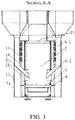
- Each of the feed tubes 4 may include an upright tube 4.1 and a slant tube 4.2 as is generally illustrated in FIG. 3 .
- Each slant tube 4.2 is disposed at or near a bottom portion of a respective upright tube 4.1
- Fuels, such as biomass pellets, loaded and/or inserted into respective hoppers 3 pass through the upright tubes 4.1 into respective slant tubes 4.2 That is, an upright tube 4.1 is joined to a respective hopper 3 via a respective slant tube 4.2.
- a first end portion of an upright tube 4.1 includes an aperture that opens into a bottom of a respective hopper 3 and a second end portion of the upright tube 4.1, disposed on opposite the first end portion of the upright tube 4.1, joins and/or connects the upright tube 4.1 to a third end portion of a respective slant tube 4.2.
- a fourth end portion of the slant tube 4.2, disposed opposite the third end portion of the slant tube 4.2, includes an aperture that opens into the firebox 2. Fuels, such as biomass pellets, may pass through the aperture associated with the fourth end portion of the slant tube 4.2 into the firebox 2.
- Each upright tube 4.1 may utilize gravity in order to draw the fuels down through each upright tube 4.1, through respective slant tubes 4.2, for feeding the fuels into the firebox 2.
- the dimensions of each upright tube 4.1 and each slant tube 4.2 may provide a means for reducing an amount of time the fuels are inside the upright tubes 4.1 and the slant tubes 4.2.
- a casing 26 may be fixedly secured to a portion of the stove body 1.
- Each upright tube 4.1 is disposed within a respective casing 26.
- a first interlayer 13 is arranged and/or disposed between the casing 26 and the stove body 1. The first interlayer 13 connects to ambient air with a first vent 15.
- a second interlayer 14 is arranged and/or disposed between the casing 26 and the upright tube 4.1. The second interlayer 14 connects to ambient air with a second vent 16.
- the fuels within in the upright tube 4.1 can avoid contact with the stove body 1 in a long time and a close distance, which prevents the fuels inside the upright tube 4.1 from overheating and/or combusting.
- the firebox 2 may be coupled with an air intake pipe 18, inside which the fourth end portion of the slant tube 4.2 can be disposed.
- the third vent 17 can be arranged and/or disposed on an outside surface of the casing 26, with which the air intake pipe 18 connects to ambient air.
- the fourth end portion of the slant tube 4.2 can be arranged as enclosed within the air intake pipe 18, pointing in a direction along incoming air (an inward wind), therefore simultaneously raises combustion efficiency and unblocks the fuel feeding.
- a cross section of the firebox 2 comprises a circular shape, which can permit fire within the firebox 2 to spiral easily, therefore the fuels can burn more thoroughly and the combustion efficiency can be improved.
- the stove body 1 includes an exhaust 27 that connects to a chimney 20.
- the connection between chimney 20 and exhaust 27 is fixed and/or detachable.
- a length of the chimney 20 is adjustable, which includes disposed at an upper portion a fourth vent 21 that fits in a spark arrestor, and includes disposed at a top a dish-shaped chimney cap (heat reflector) 22. Due to chimney effects generated by the chimney 20, the chimney 20 can provide a natural draft that creates a pressure difference between the firebox 2 and ambient air around the stove 100, which supports combustion by the incoming air.
- the fourth vent 21 disposed at the upper portion of chimney 20 can dissipate heat, and the spark arrestor fitted therein can prevent emissions of sparks.
- the chimney cap (heat reflector) 22 can comprise a dish shape and/or have profile similar to a profile of a dish, curving downwards, which converges uprising heat from the firebox 2. Heated air is then conducted and/or directed to a lower position, by which the heated air can diffuse around areas surrounding the stove body 1 below the chimney cap (heat reflector) 22 to improve warming effect. Additionally, or alternatively, the chimney cap (head reflector) 22 can provide aesthetic benefits.
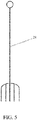
- the firebox 2 may include a grate 5.
- the grate 5 is disposed within the firebox 2, in which grate 5 is disposed lower than the connection between the feed tubes 4 and the firebox 2.
- the fuels above the grate 5 can burn into ashes that can later fall under the grate 5, by which the height of the fuels above the grate 5 can be lowered, further causing the fuels within the hoppers 3 to drop, under gravity, onto the grate 5 via the feed tubes 4, thus providing automatic control of feeding the fuels from the hoppers 3 into the firebox 2.
- the stove body 1 includes a grate support ring 6 disposed within the stove body 1, upon which the grate 5 can be placed.
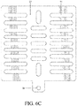
- the firebox 2 can include a grate 5', as is generally illustrated in FIG. 6A .
- the grate 5' includes one or more side walls 30. Each side wall 30 extends along a perimeter of a corresponding side of the grate 5' and extends away from the grate 5' toward a top portion of the firebox 2.
- the grate 5' includes four side walls 30, such that, the four side walls 30 form a pot or bowl shape. When the fuels, such as the biomass pellets, enter the firebox 2, the fuels fall in a concentrated pattern into the pot or bowl formed by the side walls 30. This may provide an increase in flame concentration.
- At least one of the side walls 30 includes a profile that is wide than a corresponding profile of another side wall 30.
- the at least one side wall 30 may be twice as wide as the other side walls 30.
- the at least one side wall 30 includes a plurality of apertures 31 disposed along a length of the at least one side wall 30.
- the apertures 31 may be disposed evenly or unevenly along the length of the at least one side wall 30.
- the at least one side wall 30 includes a plurality of holes disposed along a side of the at least one side wall 30 opposite the apertures 31.
- the apertures 31 are disposed along a top of the at least one side wall 30 and the holes are disposed along a bottom of the at least one side wall 30.
- the holes may be evenly or unevenly distributed along the at least one side wall 30.
- the apertures 31 substantially align with a corresponding hole on the at least one side wall 30.
- the apertures 31 and the holes may provide an increased air flow around the grate 5', increase ventilation, increase wind-ducting effect, increase fuel combustion, or a combination thereof, which may improve aerodynamic features of the grate 5' Additionally, or alternatively, because the grate 5' increases ventilation in and around the grate 5', an accumulation of ashes above the grate 5' is reduced, which can promote air flowing freely for a relatively longer period of time without external interference which may greatly extend the burning time of fuels within the firebox 2.
- the grate 5' includes a plate 32 and a shaker 33.
- the plate 32 is disposed on an upper portion of the grate 5' above the shaker 33.
- the plate 32 includes a plurality of holes 34.
- the shaker 33 includes a plurality of holes 35 disposed on the shaker 33.
- the holes 35 are disposed on the shaker 33 in staggered pattern relative to the holes 34 of the plate 32.
- the shaker 33 includes an attachment portion 36.
- the attachment portion 36 may be attached, coupled, and/or connected to an end of the grate lever 7.
- An ash tray 8 is arranged under the grate 5 and/or grate 5'. Ashes resulted from combustion of the fuels can fall from the grate 5 and/or grate 5' onto the ash tray 8.
- a grate lever 7 can be fixedly joined to the grate 5 and/or grate 5'. In some embodiments, the grate lever 7 can penetrate and extend outside the stove body 1. In some embodiments, by shaking the grate lever 7, the fire can be controlled, and the ashes can fall below the grate 5 into the ash tray 8.
- the grate lever 7 is fixedly joined to the grate 5'.
- the grate lever 7 can be actuated away from the firebox 2 (e.g., pulled out away from the firebox 2) and actuated toward the firebox 2 (e.g. pushed in toward the firebox 2).
- the shaker 33 is actuated toward the firebox 2
- the shaker 33 is actuated to a first position.
- the holes 35 are in a first position relative to the holes 34.
- the holes 34 and the holes 35 define a through bore pass through the plate 32 and the shaker 33.
- the shaker 33 is in the second position, the holes 35 are in a second position relative to the holes 34.
- the through bore defined by the holes 34 and the holes 35 may increase or decrease in size as the shaker 33 is actuated from the first position to the second position.
- actuating the grate lever 7 from the first position to the second position may cause ashes to pass through the through bore defined by the holes 34 and the holes 35 into the ash tray 8.
- the period of time it takes for ashes to fall into the ash tray 8 may be decreased.
- ventilation and/or air flow through the grate 5' may be increased as a result of the ashes falling into the ash tray 8.
- a viewport 11 is disposed on a front portion of stove body 1.
- the viewport 11 can comprise any suitable material, include heat-resisting glass.
- the front portion of the stove body 1 can include a fifth vent 23.
- the viewport 11 and the fifth vent 23 can be disposed on and/or in a stove body door 10.
- the fire within the firebox 2 can be conveniently watched through the viewport 11.
- the fifth vent 23, as arranged, can make the burning fire spiral, and provide convenient means for using a tool to poke the ashes, making them fall from the grate 5 onto the ash tray 8.
- legs 19 with adjustable height are installed, which can be conveniently adjusted to set a height for the stove body 1.
- a sixth vent 25 can be arranged at the fourth end portion of the slant tube 4.2, which can facilitate the fuels to fall into the firebox 2 from the slant tube 4.2.
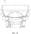
- FIGS. 7A and 7B generally illustrate a biomass pellet stove 100' according to the invention.
- the stove 100' includes one or more control levers 40 for controlling the feeding of fuels, such as biomass pellets, from the hoppers 3 to the firebox 2.
- the stove 100' includes two control levers 40 disposed on opposite sides of the stove 100'.
- Each of the control levers 40 are attached, coupled, and/or connected to a respective feed tube 4 and disposed between a respective hopper 3 and the stove body 1.
- a first control lever 40 is attached to a first feed tube 4 disposed between a first hopper 3 and the stove body 1
- a second control lever 40 is attached to a second feed tube 4 disposed between a second hopper 3 and the stove body 1.
- each control lever 40 can be actuated to a first position. For example, each control lever 40 can be pulled out away from the stove body 1 into the first position. As is generally illustrated in FIG. 7B , each control lever 40 can be actuated to a second position. For example, each control lever 40 can be pushed in toward the stove body 1. As will be described in detail below, when a control lever 40 is in the first position, the control lever 40 restricts or prevents fuels, such as biomass pellets, within a respective hopper 3 from passing into the firebox 2 through a respective feed tube 4. Conversely, when a control lever 40 is in the second position, the control lever 40 allows fuels, such as biomass pellets, within a respective hopper 3, to pass through a respective feed tube 4 into the firebox 2.
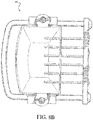
- FIGS. 8A-8C generally illustrates a control lever 40 according to the invention.
- FIG. 8A generally illustrates a control lever 40 actuated to the first position.
- FIG. 8B generally illustrates a control lever 40 actuated to a position between the first position and the second position. It should be understood that a control lever 40, according to the principles of the present invention, can be actuated to any suitable position between the first position and the second position.
- FIG. 8C generally illustrates a control lever 40 actuated to the second position.
- a control lever 40 includes a handle portion 41.
- the handle portion 41 may include a profile corresponding to a profile of a respective feed tube 4, or may include any suitable profile and/or shape.
- the handle portion 41 provides a means for lifting and/or moving the stove 100. For example, when a control lever 40 is in the first position, a respective handle portion 41 may extend away from a respective feed tubes 4. The handle portion 41 extends beyond a respective hopper 3 when the control lever 40 is in the first position.
- the handle portion 41 may be gripped by a user of the stove 100. The user may lift and/or move the stove 100 while gripping the handle portion 41. When a control lever 40 is in the second position, a respective handle portion 41 is pushed in toward the stove body 1, such that, the handle portion 41 does not extend beyond a respective hopper 3. In some embodiments, the handle portion 41 may be hidden when the control lever 40 is in the second position.
- Each of the control levers 40 includes a fork 42.
- a fork 42 includes a plurality of tines extending from a first side 43 of a respective control lever 40 toward a respective handle portion 41.
- the first side 43 is disposed opposite the handle portion 41.
- the tines may be disposed on the first side 43, such that, fuels, such as biomass pellets, are restricted and/or prohibited from passing beyond the fork 42 into a respective feed tube 4.
- a fork 42 is disposed, such that, the fork 42 can move respectively out of and into an intersection portion of a respective feed tube 4 along a lateral direction of the feed tube 4, in which the intersection can define holes or channels corresponding to the plurality of tines of the fork 42 to move through.
- the intersection portion can be through a portion of a respective feed tube 4 disposed between a respective hopper 3 and the baking area 24.
- a respective fork 42 is pushed in toward the stove body 1, such that, the plurality of tines do not extend into a respective feed tube 4, thereby allowing fuels, such as biomass pellets, within a respective hopper 3 to pass into a respective feed tube 4 into the firebox 2.
- the control lever 40 may be selectively positioned in any suitable position between the first and second position. The plurality of tines of a respective fork 42 of a control lever 40 in a position between the first and second positions may partially extend into the respective feed tube 4, thereby partially blocking fuels, such as biomass pellets, from passing into the feed tube 4 and the firebox 2.
- each control lever 40 includes a stop 44 disposed at or near the first side 43.
- the stop 44 prevents a respective fork 42 from extending beyond a respective feed tube 4 when a respective control lever 40 is actuated into the first position.
- a respective handle portion 41 may be secured to the control lever 40 via the stop 44.
- end portions 45 of a handle portion 41 may be welded to the stop 44, screwed to the stop 44, connected to the stop 44 using other suitable techniques, or a combination thereof.
- the control lever 40 comprises a unitary member that includes a handle portion 41, a fork 42, and a stop 44.
- a control lever 40 may be secured to a respective feed tube 4 by one or more brackets 46.
- the brackets 46 include a cylindrical profile and may be secured to the feed tube 4 using a suitable technique, such as welding.
- the brackets 46 are configured such that the control lever 40 can freely move between the first and second positions.
- stove 100' includes one or more secondary combustion air inlets 47.
- the stove 100' may include a secondary combustion air inlet 47 disposed on a front side of the stove body 1 on opposed sides of the firebox 2. Additionally, or alternatively, the stove 100' may include one or more secondary combustion air inlets 47 disposed on a rear side of the stove body 1 that is on an opposite side of the stove body 1 from the front side. In some embodiments, the stove 100' may include four secondary combustion air inlets 47.
- Each of the secondary combustion air inlets 47 promote a secondary combustion of fuels within the firebox 2.
- fuels such as biomass pellets
- some of the fuels may not properly combust or may inefficiently combust due to a lack of oxygen.
- Inefficiently combusted fuels may result in carbon particles rising up through the firebox 2.
- the secondary combustion air inlets 47 provide additional oxygen and/or air flow into the firebox 2 thereby promoting a secondary combustion of the carbon particles. The carbon particles are then consumed by the combustion which may result in little or no smoke exiting the firebox 2.
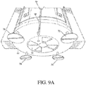
- FIGS. 9A-9C generally illustrate an air intake damper 50 according to the invention.
- the air intake damper 50 is disposed on a bottom surface 52 of the stove body 1.
- the bottom surface 52 includes an air intake 54, as is generally illustrated in FIG. 9B .
- the air intake 54 includes a plurality of air intake apertures 56.
- the air intake apertures 56 may be disposed evenly or unevenly on a surface of the air intake 54.
- the air intake apertures 56 allow air to be draw from outside of the firebox 2 into the firebox 2. Air drawn into the firebox 2 may promote combustion of the fuels, such as biomass pellets, within the firebox 2.
- the air intake damper 50 is secured to the bottom surface 52 such that the air intake damper 50 covers the air intake 54.
- the air intake damper 50 may be secured to the bottom surface 52 using any suitable technique.
- the air intake damper 50 is rotatably secured to the bottom surface 52 at or near a center of the air intake 54.
- the air intake damper 50 may be screwed, riveted, or otherwise secured to the center of the air intake 54.
- the air intake damper 50 is rotatably adjustable about the center of the air intake 54.
- the air intake damper 50 may be riveted to the air intake 54.
- the air intake damper 50 may rotate about the rivet securing the air intake damper 50 to the air intake 54.
- the air intake damper 50 includes a plurality of air control apertures 57, as is generally illustrated in FIG. 9C .
- the air control apertures 57 may be disposed evenly or unevenly on a surface of the air intake damper 50.
- the air control apertures 57 include a profile corresponding to a profile of the air intake apertures 56.
- the air control apertures 57 are disposed on the surface of the air intake damper 50 such that, when the air intake damper 50 is rotated to a first position, none of the air control apertures 57 overlap the air intake apertures 56.
- air intake damper 50 When the air intake damper 50 is in the first position, air is restricted and/or prohibited from being drawn into the firebox 2. This may reduce or extinguish the fire within the firebox 2 (e.g., due to a lack of oxygen required to continue combustion of the fuels within the firebox 2).
- each of the air control apertures 57 overlaps or substantially overlaps a corresponding air intake aperture 56. This may increase flame size associated with the fire within the firebox 2 (e.g., as a result of an increase in oxygen within the firebox 2).
- each of the air control apertures 57 partially overlaps a corresponding air intake aperture 56.
- the fire within the firebox 2 may be increased or reduced in response to the air intake damper 50 between rotated to a position between the first and second position (e.g., as the air intake damper 50 is rotated closer to the first position, the fire within the firebox 2 will be reduced, when the air intake damper 50 is rotated closer to the second position, the fire within the firebox 2 will be increased).
- the air intake damper 50 includes an air adjustment rod or control arm 58.
- the control arm 58 extends in a lateral direction away from the stove body 1.
- the control arm 58 includes a handle 59 and a connecting portion 60.
- the connecting portion 60 is disposed at a first end of the control arm 58 and may be connected to a portion of the air intake damper 50 using conventional techniques. For example, the connecting portion 60 may be welding to a surface of the air intake damper 50.
- the handle 59 is disposed at a second end opposite the connecting portion 60 and may comprise a flat profile disposed at a first end of the control arm 58.
- the handle 59 may comprise any suitable shape and/or profile other than those described herein. A user may grip the handle 59 and selectively rotate the air intake damper 50, as described above.
- FIG. 10 generally illustrates an example stove foot 70.
- the stove 100' includes a plurality of feet 70 disposed on a bottom surface 52.
- the stove 100' includes 4 feet 70 disposed equidistant from each other on the bottom surface 52.
- the feet 70 are configured to lift the bottom surface 52 off of a surface (e.g., the ground) below the stove 100'. This may promote airflow into the damper 50.
- the foot 70 includes a base 72 and a mounting shaft 74 extending away from the base.
- the mounting shaft includes a first portion 76 and a second portion 78.
- the first portion 76 may be disposed proximate the base 72 and include a profile that is wider than a profile of the second portion 78.
- the profile of the first portion 76 smoothly transitions into the profile of the second portion 78.
- the profile of the first portion 76 may include a generally conical profile and may transition into the profile of the second portion 78 which may include a generally cylindrical profile.
- the second portion 78 is dosed distally with respect to the base 72 and includes a plurality of threads.
- the plurality of threads are adapted to secure the foot 70 to the bottom surface 52.
- the foot 70 includes a securing aperture 80.
- the securing aperture 80 may be disposed on the base 72.
- the securing aperture 80 may be adapted to receive a securing mechanism, such as a stake, post, or other suitable mechanism for securing the foot 70 to a surface below the stove 100'.
- a securing mechanism such as a stake, post, or other suitable mechanism for securing the foot 70 to a surface below the stove 100'.
- each of the feet 70 (as is generally illustrated in FIG. 9A ) may be contacting a surface below the stove 100'.
- a first end of a stake may be inserted into corresponding ones of the securing apertures 80 and a second end of the stake may wrap around an edge of the base 72 proximate the securing aperture 80. This may reduce the risk that the stove 100' may be tipped over.
Landscapes
- Engineering & Computer Science (AREA)
- Chemical & Material Sciences (AREA)
- Combustion & Propulsion (AREA)
- Mechanical Engineering (AREA)
- General Engineering & Computer Science (AREA)
- Physics & Mathematics (AREA)
- Thermal Sciences (AREA)
- Solid-Fuel Combustion (AREA)
Claims (12)
- Ofen (100'), der Biomasse-Pellets als Brennstoff verwendet, umfassend:einen Ofenkörper (1), der einen Feuerraum (2) beinhaltet;mindestens einen Fülltrichter (3) zur Aufnahme von Brennstoffen; undmindestens ein Zuführungsrohr (4), das sich zwischen dem mindestens einen Fülltrichter und dem Feuerraum erstreckt; undmindestens einen Steuerhebel (40), der an dem mindestens einen Zuführungsrohr angeordnet ist;wobei Brennstoffe in dem mindestens einen Fülltrichter daran gehindert werden, entlang des mindestens einen Zuführungsrohrs in den Feuerraum einzutreten, wenn sich der mindestens eine Steuerhebel in einer ersten Stellung befindet, und Brennstoffe in dem mindestens einen Fülltrichter unter Schwerkrafteinwirkung entlang des mindestens einen Zuführungsrohrs in den Feuerraum eintreten, wenn sich der mindestens eine Steuerhebel in einer zweiten Stellung befindet, wobei der mindestens eine Steuerhebel seitlich an dem mindestens einen Zuführungsrohr angeordnet ist, undwobei der mindestens eine Steuerhebel eine Gabel (42) beinhaltet, die mehrere Zinken aufweist, die sich von einer ersten Seite (43) des mindestens einen Steuerhebels aus erstrecken und jeweils aus einem und in einen Kreuzungsabschnitt des Zuführungsrohrs bewegbar sind, dadurch gekennzeichnet, dassdie Gabel entlang einer Querrichtung des Zuführungsrohrs bewegbar ist und der mindestens eine Steuerhebel einen Griffabschnitt (41) beinhaltet, der von einem Benutzer des Ofens gegriffen wird, um den Ofen anzuheben und/oder zu bewegen.
- Ofen nach Anspruch 1, der ferner zwei Fülltrichter (3) umfasst, wobei die zwei Fülltrichter auf gegenüberliegenden Seiten des Ofens angeordnet sind, wobei sich ein jeweiliges Zuführungsrohr (4) zwischen jedem der zwei Fülltrichter hin zum Feuerraum erstreckt, und wobei ein jeweiliger Steuerhebel (40) seitlich an jedem Zuführungsrohr angeordnet ist.
- Ofen nach Anspruch 2, wobei ein Querschnitt des Feuerraums kreisförmig ist und die zwei Fülltrichter in Bezug auf eine Mittellinie des Feuerraums symmetrisch ausgelegt sind.
- Ofen nach Anspruch 2, wobei die zwei Steuerhebel auf gegenüberliegenden Seiten des Ofens angeordnet sind.
- Ofen nach Anspruch 4, wobei die Steuerhebel dafür vorgesehen sind, gegriffen zu werden, wenn sie sich in ihrer jeweiligen ersten Stellung befinden.
- Ofen nach Anspruch 1, wobei die Gabel das mindestens eine Zuführungsrohr seitlich schneidet und ein Eintreten von Brennstoffen aus dem mindestens einen Fülltrichter in den Feuerraum verhindert, wenn sich der mindestens eine Steuerhebel in der ersten Stellung befindet.
- Ofen nach Anspruch 1, wobei der Griffabschnitt (41) über den mindestens einen Fülltrichter hinausragt, wenn sich der mindestens eine Steuerhebel in der ersten Stellung befindet.
- Ofen nach Anspruch 1, wobei sich eine Fülltrichterabdeckung (12) auf einem oberen Abschnitt des mindestens einen Fülltrichters befindet.
- Ofen nach Anspruch 1, der ferner einen Rost (5, 5') umfasst, der in dem Feuerraum angeordnet ist und mehrere Seitenwände (30) aufweist, die sich entlang eines Umfangs des Rosts erstrecken, wobei Brennstoffe in den Feuerraum entlang des mindestens einen Zuführungsrohrs auf den Rost eintreten.
- Ofen nach Anspruch 9, wobei der Rost eine Platte (32) beinhaltet, die über einer Schütteleinrichtung (33) angeordnet ist, wobei die Schütteleinrichtung mehrere Löcher (35) aufweist, die gegenüber mehreren Löchern (34), die auf der Platte angeordnet sind, versetzt sind.
- Ofen nach Anspruch 10, wobei Asche auf dem Rost durch die mehreren Löcher der Platte und durch die mehreren Löcher auf der Schütteleinrichtung hindurchtritt, wenn die Schütteleinrichtung zwischen einer ersten und einer zweiten Stellung betrieben wird.
- Ofen nach Anspruch 1, der ferner eine Lufteinlassklappe (50) umfasst, die drehbar an einem Lufteinlass (54) befestigt ist, der an einer Unterseite (52) des Ofens angeordnet ist, wobei die Lufteinlassklappe einen Steuerarm (58) beinhaltet, der die Lufteinlassklappe dreht.
Applications Claiming Priority (1)
| Application Number | Priority Date | Filing Date | Title |
|---|---|---|---|
| US15/465,274 US10508814B2 (en) | 2016-05-11 | 2017-03-21 | Biomass pellet stove |
Publications (2)
| Publication Number | Publication Date |
|---|---|
| EP3379146A1 EP3379146A1 (de) | 2018-09-26 |
| EP3379146B1 true EP3379146B1 (de) | 2020-04-08 |
Family
ID=60295099
Family Applications (1)
| Application Number | Title | Priority Date | Filing Date |
|---|---|---|---|
| EP18156603.5A Active EP3379146B1 (de) | 2017-03-21 | 2018-02-14 | Biomasse-pelletofen |
Country Status (5)
| Country | Link |
|---|---|
| US (1) | US10508814B2 (de) |
| EP (1) | EP3379146B1 (de) |
| CN (1) | CN108626752B (de) |
| DK (1) | DK3379146T3 (de) |
| PT (1) | PT3379146T (de) |
Families Citing this family (9)
| Publication number | Priority date | Publication date | Assignee | Title |
|---|---|---|---|---|
| CN204665370U (zh) * | 2015-05-12 | 2015-09-23 | 青岛简洁家居有限公司 | 一种以生物质颗粒为燃料的炉子 |
| USD849900S1 (en) * | 2017-04-05 | 2019-05-28 | Qstoves Inc. | Furnace |
| USD835246S1 (en) * | 2017-05-16 | 2018-12-04 | Tanchengxian Hualong MACHINERY PLANT Sole Proprietorship Enterprise | Heating stove |
| CN107013946A (zh) * | 2017-05-26 | 2017-08-04 | 张志存 | 生物质颗粒取暖炉 |
| US11026543B2 (en) * | 2018-03-07 | 2021-06-08 | Onward Multi-Corp. Inc. | Pellet-fired cooking apparatus |
| CN115183469A (zh) * | 2021-04-07 | 2022-10-14 | 扬州华大锅炉有限公司 | 一种自动进料常压热水炉 |
| US20240053021A1 (en) * | 2022-08-12 | 2024-02-15 | Solo Brands, Llc | Outdoor heater |
| DE102023107003B4 (de) * | 2023-03-21 | 2025-05-28 | Kirchberger Metall Onlinevertrieb GmbH | Heizungsanlage zur Erzeugung thermischer Energie |
| USD1094670S1 (en) * | 2023-05-25 | 2025-09-23 | Haohong Electric Technology (Hubei) Co., Ltd. | Landscape furnace |
Family Cites Families (19)
| Publication number | Priority date | Publication date | Assignee | Title |
|---|---|---|---|---|
| FR898341A (de) * | ||||
| US2380000A (en) * | 1945-07-10 | Magazine feed solid fuel heater | ||
| GB589506A (en) * | 1944-01-24 | 1947-06-23 | Louvroil Montbard Aulnoye Sa | Method and apparatus for automatically introducing into or withdrawing from an enclosure isolated from the surrounding medium, controllable amounts of materials |
| US4416248A (en) * | 1981-01-22 | 1983-11-22 | Weber-Stephen Products Co. | Ash disposal damper for barbecue kettle |
| US5144939A (en) * | 1991-06-03 | 1992-09-08 | Christopherson Ernest W | Biomass pellet-burning orchard heaters |
| JPH11173541A (ja) * | 1997-12-12 | 1999-06-29 | Takeyuki Nakane | 蒸気噴射式自動給炭機 |
| US6397833B1 (en) * | 2000-11-16 | 2002-06-04 | Michael A Jarvi | Natural draft automatic feed pellet stove |
| US20020083944A1 (en) * | 2001-01-03 | 2002-07-04 | Darbonne Johnny R. | Pellet furnace heating apparatus |
| CA2464490C (en) * | 2004-04-15 | 2008-03-11 | Stephen Charles Brown | Combustion apparatus for solid fuel |
| US8020547B2 (en) * | 2007-08-06 | 2011-09-20 | Clarry Pellet Stove, Llc | Pellet stove |
| CN102277197B (zh) * | 2011-06-14 | 2013-07-31 | 福州市英袖能源科技有限公司 | 一种生物质垃圾裂解炉系统 |
| CN202328176U (zh) * | 2011-11-22 | 2012-07-11 | 李新民 | 一种新型燃煤锅炉 |
| CN203231330U (zh) * | 2013-04-17 | 2013-10-09 | 苏州迪森生物能源有限公司 | 生物质给料插板阀 |
| CN203727966U (zh) * | 2014-03-17 | 2014-07-23 | 国家电网公司 | 分层下料式流化原煤仓 |
| CN204026702U (zh) * | 2014-08-06 | 2014-12-17 | 梁成 | 一种螺旋式炉排 |
| CN104390347B (zh) * | 2014-10-17 | 2017-05-03 | 安徽明太生物科技有限公司 | 一种节能锅炉系统 |
| US9845957B2 (en) * | 2014-12-05 | 2017-12-19 | Richard L. Hill | Pellet stove |
| CN204665370U (zh) * | 2015-05-12 | 2015-09-23 | 青岛简洁家居有限公司 | 一种以生物质颗粒为燃料的炉子 |
| CN106439788A (zh) * | 2016-09-07 | 2017-02-22 | 成都聚立汇信科技有限公司 | 新型生物质能源燃烧装置 |
-
2017
- 2017-03-21 US US15/465,274 patent/US10508814B2/en active Active
-
2018
- 2018-02-14 PT PT181566035T patent/PT3379146T/pt unknown
- 2018-02-14 DK DK18156603.5T patent/DK3379146T3/da active
- 2018-02-14 EP EP18156603.5A patent/EP3379146B1/de active Active
- 2018-03-19 CN CN201810226627.7A patent/CN108626752B/zh active Active
Non-Patent Citations (1)
| Title |
|---|
| None * |
Also Published As
| Publication number | Publication date |
|---|---|
| US10508814B2 (en) | 2019-12-17 |
| PT3379146T (pt) | 2020-09-09 |
| US20170328572A1 (en) | 2017-11-16 |
| DK3379146T3 (da) | 2020-07-06 |
| CN108626752B (zh) | 2022-02-01 |
| CN108626752A (zh) | 2018-10-09 |
| EP3379146A1 (de) | 2018-09-26 |
Similar Documents
| Publication | Publication Date | Title |
|---|---|---|
| EP3379146B1 (de) | Biomasse-pelletofen | |
| US10753616B2 (en) | Biomass pellet stove | |
| US6615821B1 (en) | Camp stove | |
| US11092342B2 (en) | Non-gas fire pit | |
| US20200224879A1 (en) | Pellet burning fire pit | |
| US7644711B2 (en) | Spark arrestor and airflow control assembly for a portable cooking or heating device | |
| JP2024543061A (ja) | 熱偏向器 | |
| KR20190068335A (ko) | 캠핑용 난로 | |
| CN107708507B (zh) | 改进用于烹调的木炭燃烧的系统及方法 | |
| CN103388840B (zh) | 无烟火炉 | |
| KR101621511B1 (ko) | 무동력 펠릿 연소장치 | |
| WO2017050270A1 (zh) | 燃烧炉炉体及燃烧炉 | |
| US20030194671A1 (en) | Recreational cyclonic burner | |
| KR101918730B1 (ko) | 화덕 겸용 난로 | |
| CA2865969A1 (en) | An oven having an enclosed heat exchange zone | |
| US20240053021A1 (en) | Outdoor heater | |
| KR102365135B1 (ko) | 열 분산 화로 | |
| KR101579086B1 (ko) | 무동력 펠릿난로 | |
| KR20110088905A (ko) | 고형물질을 연료로 사용하는 난로 | |
| KR20220060453A (ko) | 펠릿난로용 연소장치와 이것이 구비된 펠릿난로 | |
| KR200472326Y1 (ko) | 화목 난로 | |
| US10168053B2 (en) | Combustion apparatus for both firewood and pellet fuel | |
| JP3247099U (ja) | ストーブ | |
| KR102591827B1 (ko) | 열효율을 향상시켜 온실가스 배출을 최소화한 쿡스토브 | |
| RU241010U1 (ru) | Бездымная костровая чаша |
Legal Events
| Date | Code | Title | Description |
|---|---|---|---|
| PUAI | Public reference made under article 153(3) epc to a published international application that has entered the european phase |
Free format text: ORIGINAL CODE: 0009012 |
|
| STAA | Information on the status of an ep patent application or granted ep patent |
Free format text: STATUS: THE APPLICATION HAS BEEN PUBLISHED |
|
| AK | Designated contracting states |
Kind code of ref document: A1 Designated state(s): AL AT BE BG CH CY CZ DE DK EE ES FI FR GB GR HR HU IE IS IT LI LT LU LV MC MK MT NL NO PL PT RO RS SE SI SK SM TR |
|
| AX | Request for extension of the european patent |
Extension state: BA ME |
|
| STAA | Information on the status of an ep patent application or granted ep patent |
Free format text: STATUS: REQUEST FOR EXAMINATION WAS MADE |
|
| 17P | Request for examination filed |
Effective date: 20190325 |
|
| RBV | Designated contracting states (corrected) |
Designated state(s): AL AT BE BG CH CY CZ DE DK EE ES FI FR GB GR HR HU IE IS IT LI LT LU LV MC MK MT NL NO PL PT RO RS SE SI SK SM TR |
|
| STAA | Information on the status of an ep patent application or granted ep patent |
Free format text: STATUS: EXAMINATION IS IN PROGRESS |
|
| 17Q | First examination report despatched |
Effective date: 20190515 |
|
| GRAP | Despatch of communication of intention to grant a patent |
Free format text: ORIGINAL CODE: EPIDOSNIGR1 |
|
| STAA | Information on the status of an ep patent application or granted ep patent |
Free format text: STATUS: GRANT OF PATENT IS INTENDED |
|
| INTG | Intention to grant announced |
Effective date: 20191111 |
|
| GRAS | Grant fee paid |
Free format text: ORIGINAL CODE: EPIDOSNIGR3 |
|
| GRAA | (expected) grant |
Free format text: ORIGINAL CODE: 0009210 |
|
| STAA | Information on the status of an ep patent application or granted ep patent |
Free format text: STATUS: THE PATENT HAS BEEN GRANTED |
|
| AK | Designated contracting states |
Kind code of ref document: B1 Designated state(s): AL AT BE BG CH CY CZ DE DK EE ES FI FR GB GR HR HU IE IS IT LI LT LU LV MC MK MT NL NO PL PT RO RS SE SI SK SM TR |
|
| REG | Reference to a national code |
Ref country code: AT Ref legal event code: REF Ref document number: 1254874 Country of ref document: AT Kind code of ref document: T Effective date: 20200415 Ref country code: CH Ref legal event code: EP |
|
| REG | Reference to a national code |
Ref country code: DE Ref legal event code: R096 Ref document number: 602018003498 Country of ref document: DE |
|
| REG | Reference to a national code |
Ref country code: IE Ref legal event code: FG4D |
|
| REG | Reference to a national code |
Ref country code: CH Ref legal event code: NV Representative=s name: TR-IP CONSULTING LLC, CH |
|
| REG | Reference to a national code |
Ref country code: DK Ref legal event code: T3 Effective date: 20200630 |
|
| REG | Reference to a national code |
Ref country code: SE Ref legal event code: TRGR |
|
| REG | Reference to a national code |
Ref country code: NL Ref legal event code: FP |
|
| REG | Reference to a national code |
Ref country code: PT Ref legal event code: SC4A Ref document number: 3379146 Country of ref document: PT Date of ref document: 20200909 Kind code of ref document: T Free format text: AVAILABILITY OF NATIONAL TRANSLATION Effective date: 20200730 |
|
| REG | Reference to a national code |
Ref country code: LT Ref legal event code: MG4D |
|
| PG25 | Lapsed in a contracting state [announced via postgrant information from national office to epo] |
Ref country code: NO Free format text: LAPSE BECAUSE OF FAILURE TO SUBMIT A TRANSLATION OF THE DESCRIPTION OR TO PAY THE FEE WITHIN THE PRESCRIBED TIME-LIMIT Effective date: 20200708 Ref country code: IS Free format text: LAPSE BECAUSE OF FAILURE TO SUBMIT A TRANSLATION OF THE DESCRIPTION OR TO PAY THE FEE WITHIN THE PRESCRIBED TIME-LIMIT Effective date: 20200808 Ref country code: FI Free format text: LAPSE BECAUSE OF FAILURE TO SUBMIT A TRANSLATION OF THE DESCRIPTION OR TO PAY THE FEE WITHIN THE PRESCRIBED TIME-LIMIT Effective date: 20200408 Ref country code: GR Free format text: LAPSE BECAUSE OF FAILURE TO SUBMIT A TRANSLATION OF THE DESCRIPTION OR TO PAY THE FEE WITHIN THE PRESCRIBED TIME-LIMIT Effective date: 20200709 Ref country code: LT Free format text: LAPSE BECAUSE OF FAILURE TO SUBMIT A TRANSLATION OF THE DESCRIPTION OR TO PAY THE FEE WITHIN THE PRESCRIBED TIME-LIMIT Effective date: 20200408 |
|
| REG | Reference to a national code |
Ref country code: AT Ref legal event code: MK05 Ref document number: 1254874 Country of ref document: AT Kind code of ref document: T Effective date: 20200408 |
|
| PG25 | Lapsed in a contracting state [announced via postgrant information from national office to epo] |
Ref country code: LV Free format text: LAPSE BECAUSE OF FAILURE TO SUBMIT A TRANSLATION OF THE DESCRIPTION OR TO PAY THE FEE WITHIN THE PRESCRIBED TIME-LIMIT Effective date: 20200408 Ref country code: HR Free format text: LAPSE BECAUSE OF FAILURE TO SUBMIT A TRANSLATION OF THE DESCRIPTION OR TO PAY THE FEE WITHIN THE PRESCRIBED TIME-LIMIT Effective date: 20200408 Ref country code: BG Free format text: LAPSE BECAUSE OF FAILURE TO SUBMIT A TRANSLATION OF THE DESCRIPTION OR TO PAY THE FEE WITHIN THE PRESCRIBED TIME-LIMIT Effective date: 20200708 Ref country code: RS Free format text: LAPSE BECAUSE OF FAILURE TO SUBMIT A TRANSLATION OF THE DESCRIPTION OR TO PAY THE FEE WITHIN THE PRESCRIBED TIME-LIMIT Effective date: 20200408 |
|
| PG25 | Lapsed in a contracting state [announced via postgrant information from national office to epo] |
Ref country code: AL Free format text: LAPSE BECAUSE OF FAILURE TO SUBMIT A TRANSLATION OF THE DESCRIPTION OR TO PAY THE FEE WITHIN THE PRESCRIBED TIME-LIMIT Effective date: 20200408 |
|
| REG | Reference to a national code |
Ref country code: DE Ref legal event code: R097 Ref document number: 602018003498 Country of ref document: DE |
|
| PG25 | Lapsed in a contracting state [announced via postgrant information from national office to epo] |
Ref country code: AT Free format text: LAPSE BECAUSE OF FAILURE TO SUBMIT A TRANSLATION OF THE DESCRIPTION OR TO PAY THE FEE WITHIN THE PRESCRIBED TIME-LIMIT Effective date: 20200408 Ref country code: ES Free format text: LAPSE BECAUSE OF FAILURE TO SUBMIT A TRANSLATION OF THE DESCRIPTION OR TO PAY THE FEE WITHIN THE PRESCRIBED TIME-LIMIT Effective date: 20200408 Ref country code: RO Free format text: LAPSE BECAUSE OF FAILURE TO SUBMIT A TRANSLATION OF THE DESCRIPTION OR TO PAY THE FEE WITHIN THE PRESCRIBED TIME-LIMIT Effective date: 20200408 Ref country code: CZ Free format text: LAPSE BECAUSE OF FAILURE TO SUBMIT A TRANSLATION OF THE DESCRIPTION OR TO PAY THE FEE WITHIN THE PRESCRIBED TIME-LIMIT Effective date: 20200408 Ref country code: EE Free format text: LAPSE BECAUSE OF FAILURE TO SUBMIT A TRANSLATION OF THE DESCRIPTION OR TO PAY THE FEE WITHIN THE PRESCRIBED TIME-LIMIT Effective date: 20200408 Ref country code: SM Free format text: LAPSE BECAUSE OF FAILURE TO SUBMIT A TRANSLATION OF THE DESCRIPTION OR TO PAY THE FEE WITHIN THE PRESCRIBED TIME-LIMIT Effective date: 20200408 Ref country code: IT Free format text: LAPSE BECAUSE OF FAILURE TO SUBMIT A TRANSLATION OF THE DESCRIPTION OR TO PAY THE FEE WITHIN THE PRESCRIBED TIME-LIMIT Effective date: 20200408 |
|
| PLBE | No opposition filed within time limit |
Free format text: ORIGINAL CODE: 0009261 |
|
| STAA | Information on the status of an ep patent application or granted ep patent |
Free format text: STATUS: NO OPPOSITION FILED WITHIN TIME LIMIT |
|
| PG25 | Lapsed in a contracting state [announced via postgrant information from national office to epo] |
Ref country code: PL Free format text: LAPSE BECAUSE OF FAILURE TO SUBMIT A TRANSLATION OF THE DESCRIPTION OR TO PAY THE FEE WITHIN THE PRESCRIBED TIME-LIMIT Effective date: 20200408 Ref country code: SK Free format text: LAPSE BECAUSE OF FAILURE TO SUBMIT A TRANSLATION OF THE DESCRIPTION OR TO PAY THE FEE WITHIN THE PRESCRIBED TIME-LIMIT Effective date: 20200408 |
|
| 26N | No opposition filed |
Effective date: 20210112 |
|
| PG25 | Lapsed in a contracting state [announced via postgrant information from national office to epo] |
Ref country code: SI Free format text: LAPSE BECAUSE OF FAILURE TO SUBMIT A TRANSLATION OF THE DESCRIPTION OR TO PAY THE FEE WITHIN THE PRESCRIBED TIME-LIMIT Effective date: 20200408 |
|
| PG25 | Lapsed in a contracting state [announced via postgrant information from national office to epo] |
Ref country code: MC Free format text: LAPSE BECAUSE OF FAILURE TO SUBMIT A TRANSLATION OF THE DESCRIPTION OR TO PAY THE FEE WITHIN THE PRESCRIBED TIME-LIMIT Effective date: 20200408 |
|
| PG25 | Lapsed in a contracting state [announced via postgrant information from national office to epo] |
Ref country code: LU Free format text: LAPSE BECAUSE OF NON-PAYMENT OF DUE FEES Effective date: 20210214 |
|
| PG25 | Lapsed in a contracting state [announced via postgrant information from national office to epo] |
Ref country code: PT Free format text: LAPSE BECAUSE OF NON-PAYMENT OF DUE FEES Effective date: 20211115 |
|
| PGFP | Annual fee paid to national office [announced via postgrant information from national office to epo] |
Ref country code: DK Payment date: 20211227 Year of fee payment: 5 Ref country code: SE Payment date: 20211223 Year of fee payment: 5 |
|
| PGFP | Annual fee paid to national office [announced via postgrant information from national office to epo] |
Ref country code: CH Payment date: 20211224 Year of fee payment: 5 Ref country code: BE Payment date: 20211222 Year of fee payment: 5 |
|
| PG25 | Lapsed in a contracting state [announced via postgrant information from national office to epo] |
Ref country code: CY Free format text: LAPSE BECAUSE OF FAILURE TO SUBMIT A TRANSLATION OF THE DESCRIPTION OR TO PAY THE FEE WITHIN THE PRESCRIBED TIME-LIMIT Effective date: 20200408 |
|
| PG25 | Lapsed in a contracting state [announced via postgrant information from national office to epo] |
Ref country code: HU Free format text: LAPSE BECAUSE OF FAILURE TO SUBMIT A TRANSLATION OF THE DESCRIPTION OR TO PAY THE FEE WITHIN THE PRESCRIBED TIME-LIMIT; INVALID AB INITIO Effective date: 20180214 |
|
| REG | Reference to a national code |
Ref country code: DK Ref legal event code: EBP Effective date: 20230228 |
|
| REG | Reference to a national code |
Ref country code: CH Ref legal event code: PL |
|
| REG | Reference to a national code |
Ref country code: SE Ref legal event code: EUG |
|
| REG | Reference to a national code |
Ref country code: BE Ref legal event code: MM Effective date: 20230228 |
|
| PG25 | Lapsed in a contracting state [announced via postgrant information from national office to epo] |
Ref country code: SE Free format text: LAPSE BECAUSE OF NON-PAYMENT OF DUE FEES Effective date: 20230215 Ref country code: LI Free format text: LAPSE BECAUSE OF NON-PAYMENT OF DUE FEES Effective date: 20230228 Ref country code: CH Free format text: LAPSE BECAUSE OF NON-PAYMENT OF DUE FEES Effective date: 20230228 |
|
| PG25 | Lapsed in a contracting state [announced via postgrant information from national office to epo] |
Ref country code: DK Free format text: LAPSE BECAUSE OF NON-PAYMENT OF DUE FEES Effective date: 20230228 |
|
| PG25 | Lapsed in a contracting state [announced via postgrant information from national office to epo] |
Ref country code: BE Free format text: LAPSE BECAUSE OF NON-PAYMENT OF DUE FEES Effective date: 20230228 |
|
| PGFP | Annual fee paid to national office [announced via postgrant information from national office to epo] |
Ref country code: IE Payment date: 20240214 Year of fee payment: 7 Ref country code: NL Payment date: 20240215 Year of fee payment: 7 |
|
| PG25 | Lapsed in a contracting state [announced via postgrant information from national office to epo] |
Ref country code: MK Free format text: LAPSE BECAUSE OF FAILURE TO SUBMIT A TRANSLATION OF THE DESCRIPTION OR TO PAY THE FEE WITHIN THE PRESCRIBED TIME-LIMIT Effective date: 20200408 |
|
| PGFP | Annual fee paid to national office [announced via postgrant information from national office to epo] |
Ref country code: DE Payment date: 20240215 Year of fee payment: 7 |
|
| PG25 | Lapsed in a contracting state [announced via postgrant information from national office to epo] |
Ref country code: TR Free format text: LAPSE BECAUSE OF FAILURE TO SUBMIT A TRANSLATION OF THE DESCRIPTION OR TO PAY THE FEE WITHIN THE PRESCRIBED TIME-LIMIT Effective date: 20200408 |
|
| PG25 | Lapsed in a contracting state [announced via postgrant information from national office to epo] |
Ref country code: MT Free format text: LAPSE BECAUSE OF FAILURE TO SUBMIT A TRANSLATION OF THE DESCRIPTION OR TO PAY THE FEE WITHIN THE PRESCRIBED TIME-LIMIT Effective date: 20200408 |
|
| PGFP | Annual fee paid to national office [announced via postgrant information from national office to epo] |
Ref country code: FR Payment date: 20250228 Year of fee payment: 8 |
|
| PGFP | Annual fee paid to national office [announced via postgrant information from national office to epo] |
Ref country code: GB Payment date: 20250227 Year of fee payment: 8 |
|
| REG | Reference to a national code |
Ref country code: DE Ref legal event code: R119 Ref document number: 602018003498 Country of ref document: DE |
|
| REG | Reference to a national code |
Ref country code: NL Ref legal event code: MM Effective date: 20250301 |
|
| PG25 | Lapsed in a contracting state [announced via postgrant information from national office to epo] |
Ref country code: NL Free format text: LAPSE BECAUSE OF NON-PAYMENT OF DUE FEES Effective date: 20250301 |
|
| PG25 | Lapsed in a contracting state [announced via postgrant information from national office to epo] |
Ref country code: DE Free format text: LAPSE BECAUSE OF NON-PAYMENT OF DUE FEES Effective date: 20250902 |
|
| PG25 | Lapsed in a contracting state [announced via postgrant information from national office to epo] |
Ref country code: IE Free format text: LAPSE BECAUSE OF NON-PAYMENT OF DUE FEES Effective date: 20250214 |