EP3379008A1 - Verriegelungseinrichtung - Google Patents
Verriegelungseinrichtung Download PDFInfo
- Publication number
- EP3379008A1 EP3379008A1 EP18160188.1A EP18160188A EP3379008A1 EP 3379008 A1 EP3379008 A1 EP 3379008A1 EP 18160188 A EP18160188 A EP 18160188A EP 3379008 A1 EP3379008 A1 EP 3379008A1
- Authority
- EP
- European Patent Office
- Prior art keywords
- locking device
- bolt
- lever
- wing
- Prior art date
- Legal status (The legal status is an assumption and is not a legal conclusion. Google has not performed a legal analysis and makes no representation as to the accuracy of the status listed.)
- Granted
Links
Images

Classifications
-
- E—FIXED CONSTRUCTIONS
- E05—LOCKS; KEYS; WINDOW OR DOOR FITTINGS; SAFES
- E05C—BOLTS OR FASTENING DEVICES FOR WINGS, SPECIALLY FOR DOORS OR WINDOWS
- E05C1/00—Fastening devices with bolts moving rectilinearly
- E05C1/02—Fastening devices with bolts moving rectilinearly without latching action
- E05C1/06—Fastening devices with bolts moving rectilinearly without latching action with operating handle or equivalent member moving otherwise than rigidly with the bolt
-
- E—FIXED CONSTRUCTIONS
- E05—LOCKS; KEYS; WINDOW OR DOOR FITTINGS; SAFES
- E05B—LOCKS; ACCESSORIES THEREFOR; HANDCUFFS
- E05B15/00—Other details of locks; Parts for engagement by bolts of fastening devices
- E05B15/10—Bolts of locks or night latches
- E05B15/101—Spring-retracted bolts
-
- E—FIXED CONSTRUCTIONS
- E05—LOCKS; KEYS; WINDOW OR DOOR FITTINGS; SAFES
- E05B—LOCKS; ACCESSORIES THEREFOR; HANDCUFFS
- E05B63/00—Locks or fastenings with special structural characteristics
- E05B63/0004—Additional locks added to existing lock arrangements
- E05B63/0008—Mounted on the hinged side of the wing
-
- E—FIXED CONSTRUCTIONS
- E05—LOCKS; KEYS; WINDOW OR DOOR FITTINGS; SAFES
- E05B—LOCKS; ACCESSORIES THEREFOR; HANDCUFFS
- E05B63/00—Locks or fastenings with special structural characteristics
- E05B63/04—Locks or fastenings with special structural characteristics for alternative use on the right-hand or left-hand side of wings
-
- E—FIXED CONSTRUCTIONS
- E05—LOCKS; KEYS; WINDOW OR DOOR FITTINGS; SAFES
- E05D—HINGES OR SUSPENSION DEVICES FOR DOORS, WINDOWS OR WINGS
- E05D15/00—Suspension arrangements for wings
- E05D15/48—Suspension arrangements for wings allowing alternative movements
- E05D15/52—Suspension arrangements for wings allowing alternative movements for opening about a vertical as well as a horizontal axis
- E05D15/526—Safety devices
- E05D2015/5263—Safety devices acting parallel to the plane of the wing
Definitions
- the invention relates to a locking device for a relative to a frame about a horizontal axis tiltable in a tilted position and rotatable about a vertical axis in a rotational position and movable into a closed position in the frame closed wing of a window, a French door or the like, with a for mounting on the wing provided wing-side fitting part and provided for mounting on the frame frame side fitting part, wherein a latch of one of the fitting parts in a pocket of the other of the fitting parts is movable and a control device for moving the bolt into the pocket in tilting and / or closed position wings and movement of the bolt out of the pocket is formed in located in rotational position wing.
- Turnable and tiltable windows have in the crossing region of the axes on a corner bearing, which allows both a tilting of the wing about the horizontal axis, as well as a rotation about the vertical axis. Often the corner bearing is inserted into each other and offers an unauthorized Aufhebel leak only a small resistance.
- a controllable by the movement of a wing locking device is from the GB 2 324 331 A known.
- the control device has a control gear for swinging the bolt.
- the control device has a button which detects the position of the wing relative to the frame. When lying in the frame wing of the bolt is swung out and penetrates into a pocket of the opposite component.
- this locking device is difficult to use in a wing with a corner bearing, because a mounted on a horizontal bar latch would block the movement of the wing in the tilted position and arranged in a vertical bar latch would block the movement in rotational position. The penetrating into the bag latch would be charged in these cases transversely to its pivotal movement.
- the invention is based on the problem of providing a locking device which ensures a further aggravation of a Aufhebel eggss regardless of a drive rod by the movement of the wing relative to the frame.
- the bolt can be moved in relation to the position of the wing relative to the frame.
- a preferred mounting position on the window with the bolt on the horizontal axis and the pocket at or near the intersection of the axes of the latch is moved in a tilted position of the wing into the pocket and removed in a rotational position of the wing from the bag.
- control device structurally particularly simple when the control device has a deflectable button for detecting the position of the wing relative to the frame.
- the button can be deflected in the assembled state during the movement of the wing against the frame, so that the control device for movement of the bolt can be controlled.
- the transmission of the pivotal movement of the wing on the longitudinal movement of the bolt is particularly simple according to another advantageous embodiment of the invention, when a pivotable control lever is supported on the longitudinally displaceable bolt and that a pivot lever is mounted on the bolt leading fitting part and that the control lever and the pivot lever are arranged to a knee lever.
- the formation of the toggle lever can produce a particularly large sliding path of the bolt with small deflections of the wing. By appropriate lengths of the pivot lever and the control lever, the intended path of the bolt can be easily set.
- the button could for example be made in one piece with the control lever.
- a particularly large stroke of the bolt can be easily generated according to another advantageous embodiment of the invention, when the button is arranged on the pivot lever.
- control device structurally particularly simple when the support of the control lever has a bearing on the bolt.
- the locking device is particularly compact according to another advantageous embodiment of the invention, when the pivot lever and the control lever are superimposed.
- a reliable positive guidance of the bolt can be produced according to another advantageous embodiment of the invention, when the bolt is biased in an open position located outside the bag.
- Tolerances of the wing relative to the frame can be easily compensated according to another advantageous embodiment of the invention, when the fitting part having the pocket has adjusting means for adjusting the height of the pocket.
- the locking device can be used according to another advantageous embodiment of the invention in right and left stop wings when the bag is designed symmetrically.
- the wing can tilt according to another advantageous embodiment of the invention in very large tilted positions of the frame when the bag is transverse to the direction of movement slidably guided by the bolt and is biased by a spring element into a basic position.
- the components locking device can be particularly space-saving in grooves in the frame and in order, when the bolt has a bend at its free, provided for penetration into the pocket end.
- FIG. 1 shows a window with a pivotable against a frame 1 wings 2 and with a drive rod fitting 3.
- the drive rod fitting 3 has to drive a longitudinally displaceable drive rod 4, a handle 5 and a plurality of closures 6.
- the wing 2 can be on the closures 6 in a frame in the first lock lying closed position. Furthermore, the wing 2 can tilt about a horizontal axis 7 in a tilted position and rotate about a vertical axis 8 in a rotational position.
- a corner bearing 9 is arranged at the intersection of the axes 7, 8, a corner bearing 9 is arranged.
- the window has a locking device 10 with a frame-side fitting part 11 and a wing-side fitting part 12.
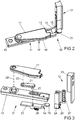
- the locking device 10 is in FIG. 2 enlarged and shown in perspective.
- the frame-side fitting part 11 has a longitudinally displaceably guided bolt 13 with a bend 14. In the intended preferred mounting position, the bend 14 leads the free end 15 of the bolt 13 on the in FIG. 1 illustrated horizontal axis 7.
- the movement of the bolt 13 is generated in the assembled state via a control device 16 in dependence on the position of the wing 2 relative to the frame 1.
- the control device 16 has a pivot lever 17 with a button 18.
- the frame-side fitting part 11 has a base body 19 to be screwed to the frame 19 for supporting the pivot lever 17 and for guiding the bolt 13. In the illustrated position, the pivot lever 17 is above the base body Pivoted 19 and the bolt 13 fully extended.
- the wing-side fitting part has a pocket 20.
- the pocket 20 receives the free end 15 of the latch 13.
- the locking device 10 prevents a lever in the FIG. 1 illustrated wing 2 transverse to the horizontal axis. 7
- FIG. 3 shows in an exploded view of the individual components of the locking device 10 FIG. 2 ,
- the control lever 16 has a control lever 21 arranged below the pivot lever 17.
- the control lever 21 has a bearing 22 in the bolt 13 and a bearing 23 in the pivot lever 17. Swivel lever 17 and control lever 21 together form a toggle, so that upon deflection of the pivot lever 17 the toggle lever is moved in an extended or angled position. Thus, the latch 13 is extended or retracted into the main body 19.
- FIG. 3 shows that the pocket 20 is bounded symmetrically by a bracket 24 and is mounted on a base 25 parallel to the one in FIG FIG. 1 shown vertical axis 8 is guided.
- Latch 13 and pocket 20 are each biased by a spring element 26, 27 in a basic position.
- the height of the pocket 20 may also be adjustable by an adjusting means.
- the locking device 10 can also be unlocked when the in FIG. 1 illustrated wing 2 is rotated by the frame 1 about the vertical axis 8 away.
- the bolt 13 is pulled by the force of the spring element 26 out of the pocket 20 and the pivot lever 17 is deflected with the button 18, so that the toggle lever of the pivot lever 17 and the control lever 21 is bent.
- a renewed movement of the wing 2 against the frame 1 leads to a depression of the button 18 and the associated extension of the toggle lever against the Force of the spring element 26.
- the locking device 10 is moved back into the locking position.
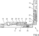
- FIG. 4 shows a sectional view of the locking device 10 FIG. 2 , Here it can be seen that the control lever 21 and the pivot lever 17 are sandwiched one above the other.
- the pivot lever 17 has a reinforcement 29 between a bearing 28 in the base body 19 and its bearing 23 on the control lever 21.
- the reinforcement 29 is slightly thicker than the height of the control lever 21st
Landscapes
- Engineering & Computer Science (AREA)
- Structural Engineering (AREA)
- Mechanical Engineering (AREA)
- Lock And Its Accessories (AREA)
Abstract
Description
- Die Erfindung betrifft eine Verriegelungseinrichtung für einen gegenüber einem Rahmen um eine horizontale Achse in eine Kippstellung kippbaren und um eine vertikale Achse in eine Drehstellung drehbaren und in eine im Rahmen liegende Schließstellung bewegbaren Flügel eines Fensters, einer Fenstertür oder dergleichen, mit einem zur Montage am Flügel vorgesehenen flügelseitigen Beschlagteil und einem zur Montage am Rahmen vorgesehenen rahmenseitigen Beschlagteil, wobei ein Riegel eines der Beschlagteile in eine Tasche des anderen der Beschlagteile bewegbar ist und eine Steuereinrichtung zur Bewegung des Riegels in die Tasche bei in Kippstellung und/oder Schließstellung befindlichen Flügel und zur Bewegung des Riegels aus der Tasche heraus bei in Drehstellung befindlichen Flügel ausgebildet ist.
- Dreh- und kippbare Fenster weisen im Kreuzungsbereich der Achsen ein Ecklager auf, welches sowohl ein Kippen des Flügels um die horizontale Achse, als auch ein Drehen um die vertikale Achse ermöglicht. Häufig ist das Ecklager ineinander gesteckt und bietet einem unberechtigten Aufhebelversuch nur einen geringen Widerstand.
- Eine von der Bewegung eines Flügels ansteuerbare Verriegelungseinrichtung ist aus der
GB 2 324 331 A - Man könnte daran denken, über eine Treibstange eines Treibstangenbeschlages auch eine Verriegelungseinrichtung nahe des Ecklagers anzutreiben. Dies erfordert jedoch einen sehr hohen baulichen Aufwand.
- Der Erfindung liegt das Problem zugrunde eine Verriegelungseinrichtung zu schaffen, welche unabhängig von einer Treibstange durch die Bewegung des Flügels gegenüber dem Rahmen eine weitere Erschwerung eines Aufhebelversuchs gewährleistet.
- Dieses Problem wird erfindungsgemäß dadurch gelöst, dass der Riegel in der vorgesehenen Montagelage parallel zur horizontalen Achse verschiebbar ist und die Tasche im anderen der Beschlagteile zur Aufnahme des freien Endes des Riegels mit ihrer Ebene orthogonal zur vorgesehenen horizontalen Achse angeordnet ist.
- Durch diese Gestaltung lässt sich der Riegel in Abhängigkeit von der Stellung des Flügels gegenüber dem Rahmen bewegen. In einer bevorzugten Montagestellung am Fenster mit dem Riegel auf der horizontalen Achse und der Tasche im oder nahe des Schnittpunktes der Achsen wird erfindungsgemäß der Riegel in einer Kippstellung des Flügels in die Tasche hinein bewegt und in einer Drehstellung des Flügels aus der Tasche entfernt. Damit ist die Steuerung der Verriegelungseinrichtung unabhängig von einem Treibstangenbeschlag. Die Verriegelungseinrichtung ermöglicht eine wesentliche Erschwerung eines Aufhebelversuches des Flügels.
- Die Steuereinrichtung gestaltet sich gemäß einer anderen vorteilhaften Weiterbildung der Erfindung konstruktiv besonders einfach, wenn die Steuereinrichtung einen auslenkbaren Taster zur Erfassung der Position des Flügels gegenüber dem Rahmen hat. Hierdurch lässt sich der Taster im montierten Zustand bei der Bewegung des Flügels gegen den Rahmen auslenken, so dass die Steuereinrichtung zur Bewegung des Riegels ansteuerbar ist.
- Die Übertragung der Schwenkbewegung des Flügels auf die Längsbewegung des Riegels gestaltet sich gemäß einer anderen vorteilhaften Weiterbildung der Erfindung besonders einfach, wenn ein schwenkbarer Steuerhebel an dem längsverschieblichen Riegel abgestützt ist und dass ein Schwenkhebel auf dem den Riegel führenden Beschlagteil gelagert ist und dass der Steuerhebel und der Schwenkhebel zu einem Kniehebel angeordnet sind. Durch die Bildung des Kniehebels lässt sich ein besonders großer Schiebeweg des Riegels bei geringen Auslenkungen des Flügels erzeugen. Durch entsprechende Längen des Schwenkhebels und des Steuerhebels lässt sich der vorgesehene Weg des Riegels einfach festlegen.
- Der Taster könnte beispielsweise einstückig mit dem Steuerhebel gefertigt sein. Ein besonders großer Hubweg des Riegels lässt sich jedoch gemäß einer anderen vorteilhaften Weiterbildung der Erfindung einfach erzeugen, wenn der Taster auf dem Schwenkhebel angeordnet ist.
- Eine frühzeitige Erfassung der Bewegung des Flügels lässt sich gemäß einer anderen vorteilhaften Weiterbildung der Erfindung einfach sicherstellen, wenn der Taster auf einem die Abstützung an dem Steuerhebel überragenden Ende des Schwenkhebels angeordnet ist.
- Die Steuereinrichtung gestaltet sich gemäß einer anderen vorteilhaften Weiterbildung der Erfindung konstruktiv besonders einfach, wenn die Abstützung des Steuerhebels an dem Riegel eine Lagerung aufweist.
- Zur Vereinfachung des Aufbaus der Steuereinrichtung und der Montage trägt es gemäß einer anderen vorteilhaften Weiterbildung der Erfindung bei, wenn der Schwenkhebel und der Steuerhebel über eine Lagerung miteinander verbunden sind.
- Die Verriegelungseinrichtung gestaltet sich gemäß einer anderen vorteilhaften Weiterbildung der Erfindung besonders kompakt, wenn der Schwenkhebel und der Steuerhebel übereinander liegen.
- Eine zuverlässige Zwangsführung des Riegels lässt sich gemäß einer anderen vorteilhaften Weiterbildung der Erfindung erzeugen, wenn der Riegel in eine außerhalb der Tasche befindlichen Offenstellung vorgespannt ist.
- Toleranzen des Flügels gegenüber dem Rahmen lassen sich gemäß einer anderen vorteilhaften Weiterbildung der Erfindung einfach ausgleichen, wenn das die Tasche aufweisende Beschlagteil Stellmittel zur Verstellung der Höhe der Tasche aufweist.
- Die Verriegelungseinrichtung lässt sich gemäß einer anderen vorteilhaften Weiterbildung der Erfindung bei rechts- und links anschlagenden Flügeln einsetzen, wenn die Tasche symmetrisch gestaltet ist.
- Der Flügel lässt sich gemäß einer anderen vorteilhaften Weiterbildung der Erfindung in sehr große Kippstellungen von dem Rahmen wegkippen, wenn die Tasche quer zur Bewegungsrichtung des Riegels verschieblich geführt und von einem Federelement in eine Grundstellung vorgespannt ist.
- Die Bauteile Verriegelungseinrichtung lassen sich besonders platzsparend in Nuten im Rahmen und im anordnen, wenn der Riegel an seinem freien, zum Eindringen in die Tasche vorgesehenen Ende eine Abkröpfung hat.
- Die Erfindung lässt zahlreiche Ausführungsformen zu. Zur weiteren Verdeutlichung ihres Grundprinzips ist eine davon in der Zeichnung dargestellt und wird nachfolgend beschrieben. Diese zeigt in
- Fig. 1
- ein Fenster mit einer Verriegelungseinrichtung,
- Fig. 2
- vergrößert eine perspektivische Darstellung der Verriegelungseinrichtung aus
Figur 1 - Fig. 3
- perspektivisch eine Darstellung der einzelnen Bauteile der Verriegelungseinrichtung aus
Figur 2 , - Fig. 4
- einen Längsschnitt durch die Verriegelungseinrichtung aus
Figur 2 . -
Figur 1 zeigt ein Fenster mit einem gegen einen Rahmen 1 schwenkbaren Flügel 2 und mit einem Treibstangenbeschlag 3. Der Treibstangenbeschlag 3 hat zum Antrieb einer längsverschieblichen Treibstange 4 eine Handhabe 5 und mehrere Verschlüsse 6. Der Flügel 2 lässt sich über die Verschlüsse 6 in einer im Rahmen 1 liegenden Schließstellung verriegeln. Weiterhin lässt sich der Flügel 2 um eine horizontale Achse 7 in eine Kippstellung kippen und über eine vertikale Achse 8 in eine Drehstellung drehen. Im Schnittpunkt der Achsen 7, 8 ist ein Ecklager 9 angeordnet. Nahe des Ecklagers 9 hat das Fenster eine Verriegelungseinrichtung 10 mit einem rahmenseitigen Beschlagteil 11 und einem flügelseitigen Beschlagteil 12. - Die Verriegelungseinrichtung 10 ist in
Figur 2 vergrößert und perspektivisch dargestellt. Das rahmenseitige Beschlagteil 11 hat einen längs verschieblich geführten Riegel 13 mit einer Abkröpfung 14. In der vorgesehenen bevorzugten Montagelage führt die Abkröpfung 14 das freie Ende 15 des Riegels 13 auf die inFigur 1 dargestellte horizontale Achse 7. Die Bewegung des Riegels 13 wird im montierten Zustand über eine Steuereinrichtung 16 in Abhängigkeit von der Stellung des Flügels 2 gegenüber dem Rahmen 1 erzeugt. Hierfür hat die Steuereinrichtung 16 einen Schwenkhebel 17 mit einem Taster 18. Das rahmenseitige Beschlagteil 11 hat einen mit dem Rahmen 1 zu verschraubenden Grundkörper 19 zur Lagerung des Schwenkhebels 17 und zur Führung des Riegels 13. In der dargestellten Stellung ist der Schwenkhebel 17 über den Grundkörper 19 geschwenkt und der Riegel 13 vollständig ausgefahren. - Das flügelseitige Beschlagteil hat eine Tasche 20. In der dargestellten, vollständig ausgefahrenen Stellung des Riegels 13 nimmt die Tasche 20 das freie Ende 15 des Riegels 13 auf. Dies kennzeichnet eine verriegelte Stellung der Verriegelungseinrichtung 10, in der die Beschlagteile 11, 12 über den Riegel 13 miteinander verbunden sind. In dieser Stellung verhindert die Verriegelungseinrichtung 10 ein Aufhebeln des in
Figur 1 dargestellten Flügels 2 quer zur horizontalen Achse 7. -
Figur 3 zeigt in einer Explosionsdarstellung die einzelnen Bauteile der Verriegelungseinrichtung 10 ausFigur 2 . Die Steuereinrichtung 16 hat einen unterhalb des Schwenkhebels 17 angeordneten Steuerhebel 21. Der Steuerhebel 21 hat eine Lagerung 22 in dem Riegel 13 und eine Lagerung 23 in dem Schwenkhebel 17. Schwenkhebel 17 und Steuerhebel 21 bilden zusammen einen Kniehebel, so dass bei einer Auslenkung des Schwenkhebels 17 der Kniehebel in eine gestreckte oder abgewinkelte Lage bewegt wird. Damit wird der Riegel 13 ausgefahren oder in den Grundkörper 19 zurückgezogen. - Weiterhin zeigt
Figur 3 , dass die Tasche 20 von einem Bügel 24 symmetrisch begrenzt wird und auf einem Grundkörper 25 parallel zu der inFigur 1 dargestellten vertikalen Achse 8 geführt ist. Riegel 13 und Tasche 20 sind jeweils von einem Federelement 26, 27 in eine Grundstellung vorgespannt. In einer nicht dargestellten Ausführungsform kann die Höhe der Tasche 20 auch von einem Stellmittel einstellbar sein. - Ausgehend von der in
Figur 2 dargestellten Verriegelungsstellung kann die Verriegelungseinrichtung 10 auch entriegelt werden, wenn der inFigur 1 dargestellte Flügel 2 von dem Rahmen 1 um die vertikale Achse 8 weg gedreht wird. Dabei wird der Riegel 13 durch die Kraft des Federelementes 26 aus der Tasche 20 gezogen und der Schwenkhebel 17 mit dem Taster 18 ausgelenkt, so dass der Kniehebel von Schwenkhebel 17 und Steuerhebel 21 gebeugt ist. Ein erneutes Bewegen des Flügels 2 gegen den Rahmen 1 führt zu einem Eindrücken des Tasters 18 und der damit verbundenen Streckung des Kniehebels gegen die Kraft des Federelementes 26. Damit wird die Verriegelungseinrichtung 10 wieder in die Verriegelungsstellung bewegt. -
Figur 4 zeigt eine Schnittdarstellung der Verriegelungseinrichtung 10 ausFigur 2 . Hierbei ist zu erkennen, dass der Steuerhebel 21 und der Schwenkhebel 17 sandwichartig übereinander liegen. Der Schwenkhebel 17 hat eine Verstärkung 29 zwischen einer Lagerung 28 im Grundkörper 19 und seiner Lagerung 23 am Steuerhebel 21. Die Verstärkung 29 ist geringfügig dicker als die Höhe des Steuerhebels 21.
Claims (13)
- Verriegelungseinrichtung (10) für einen gegenüber einem Rahmen (1) um eine horizontale Achse (7) in eine Kippstellung kippbaren und um eine vertikale Achse (8) in eine Drehstellung drehbaren und in eine im Rahmen (1) liegende Schließstellung bewegbaren Flügel (2) eines Fensters, einer Fenstertür oder dergleichen, mit einem zur Montage am Flügel (2) vorgesehenen flügelseitigen Beschlagteil (12) und einem zur Montage am Rahmen (1) vorgesehenen rahmenseitigen Beschlagteil (11), wobei ein Riegel (13) eines der Beschlagteile (11) in eine Tasche (20) des anderen der Beschlagteile (12) bewegbar ist und eine Steuereinrichtung (16) zur Bewegung des Riegels (13) in die Tasche (20) bei in Kippstellung und/oder Schließstellung befindlichen Flügel (2) und zur Bewegung des Riegels (13) aus der Tasche (20) heraus bei in Drehstellung befindlichen Flügel (2) ausgebildet ist, dadurch gekennzeichnet, dass der Riegel (13) in der vorgesehenen Montagelage parallel zur horizontalen Achse (7) verschiebbar ist und die Tasche (20) im anderen der Beschlagteile (12) zur Aufnahme des freien Endes (15) des Riegels (13) mit ihrer Ebene orthogonal zur vorgesehenen horizontalen Achse (7) angeordnet ist.
- Verriegelungseinrichtung nach Anspruch 1, dadurch gekennzeichnet, dass die Steuereinrichtung (16) einen auslenkbaren Taster (18) zur Erfassung der Position des Flügels (2) gegenüber dem Rahmen (1) hat.
- Verriegelungseinrichtung nach Anspruch 1 oder 2, dadurch gekennzeichnet, dass ein schwenkbarer Steuerhebel (21) an dem längs verschieblichen Riegel (13) abgestützt ist und dass ein Schwenkhebel (17) auf dem den Riegel (13) führenden Beschlagteil (11) gelagert ist und dass der Steuerhebel (21) und der Schwenkhebel (17) zu einem Kniehebel angeordnet sind.
- Verriegelungseinrichtung nach Anspruch 3, dadurch gekennzeichnet, dass der Taster (18) auf dem Schwenkhebel (17) angeordnet ist.
- Verriegelungseinrichtung nach Anspruch 4, dadurch gekennzeichnet, dass der Taster (18) auf einem die Abstützung an dem Steuerhebel (21) überragenden Ende des Schwenkhebels (17) angeordnet ist.
- Verriegelungseinrichtung nach einem der Ansprüche 2 bis 5, dadurch gekennzeichnet, dass die Abstützung des Steuerhebels (21) an dem Riegel (13) eine Lagerung (22) aufweist.
- Verriegelungseinrichtung nach einem der Ansprüche 2 bis 6, dadurch gekennzeichnet, dass der Schwenkhebel (17) und der Steuerhebel (21) über ein Lagerung (23) miteinander verbunden sind.
- Verriegelungseinrichtung nach einem der Ansprüche 2 bis 7, dadurch gekennzeichnet, dass der Schwenkhebel (17) und der Steuerhebel (21) übereinander liegen.
- Verriegelungseinrichtung nach einem der Ansprüche 1 bis 8, dadurch gekennzeichnet, dass der Riegel (13) in eine außerhalb der Tasche (20) befindlichen Offenstellung vorgespannt ist.
- Verriegelungseinrichtung nach einem der Ansprüche 1 bis 9, dadurch gekennzeichnet, dass das die Tasche (20) aufweisende Beschlagteil (12) Stellmittel zur Verstellung der Höhe der Tasche (20) aufweist.
- Verriegelungseinrichtung nach einem der Ansprüche 1 bis 10, dadurch gekennzeichnet, dass die Tasche (20) symmetrisch gestaltet ist.
- Verriegelungseinrichtung nach einem der Ansprüche 1 bis 11, dadurch gekennzeichnet, dass die Tasche (20) quer zur Bewegungsrichtung des Riegels (13) verschieblich geführt und von einem Federelement (27) in eine Grundstellung vorgespannt ist.
- Verriegelungseinrichtung nach einem der Ansprüche 1 bis 12, dadurch gekennzeichnet, dass der Riegel (13) an seinem freien, zum Eindringen in die Tasche (20) vorgesehenen Ende (15) eine Abkröpfung (14) hat.
Priority Applications (2)
| Application Number | Priority Date | Filing Date | Title |
|---|---|---|---|
| SI201830010T SI3379008T1 (sl) | 2017-03-20 | 2018-03-06 | Zaporna naprava |
| PL18160188T PL3379008T3 (pl) | 2017-03-20 | 2018-03-06 | Urządzenie ryglujące |
Applications Claiming Priority (1)
| Application Number | Priority Date | Filing Date | Title |
|---|---|---|---|
| DE102017204552.3A DE102017204552A1 (de) | 2017-03-20 | 2017-03-20 | Verriegelungseinrichtung |
Publications (2)
| Publication Number | Publication Date |
|---|---|
| EP3379008A1 true EP3379008A1 (de) | 2018-09-26 |
| EP3379008B1 EP3379008B1 (de) | 2019-09-18 |
Family
ID=61580973
Family Applications (1)
| Application Number | Title | Priority Date | Filing Date |
|---|---|---|---|
| EP18160188.1A Active EP3379008B1 (de) | 2017-03-20 | 2018-03-06 | Verriegelungseinrichtung |
Country Status (4)
| Country | Link |
|---|---|
| EP (1) | EP3379008B1 (de) |
| DE (1) | DE102017204552A1 (de) |
| PL (1) | PL3379008T3 (de) |
| SI (1) | SI3379008T1 (de) |
Citations (7)
| Publication number | Priority date | Publication date | Assignee | Title |
|---|---|---|---|---|
| DE29605592U1 (de) * | 1996-03-26 | 1997-07-24 | Mayer & Co., Salzburg | Aufdrücksperre |
| GB2324331A (en) * | 1997-04-15 | 1998-10-21 | Ian Alexander Gordon | Window lock automatically releasable on opening of the window |
| EP1728947A2 (de) * | 2005-06-01 | 2006-12-06 | Aug. Winkhaus GmbH & Co. KG | Schliesszapfen für einen Verschluss eines Treibstangenbeschlages und Verschluss für einen Treibstangenbeschlag |
| DE202008012837U1 (de) * | 2008-09-27 | 2010-03-04 | Haverkamp, Bernhard | Fenster mit verriegelbarem Beschlag |
| DE102008047194A1 (de) * | 2008-09-15 | 2010-04-15 | ABUS August Bremicker Söhne KG | Verriegelungseinheit für Fenster- oder Türflügel |
| EP2324331A1 (de) | 2008-09-12 | 2011-05-25 | Waters Technologies Corporation | Einlassprofil zur optimalen nutzung von motorkennwerten |
| DE102012103277A1 (de) * | 2012-04-16 | 2013-10-17 | REGEL-air Becks GmbH & Co. KG | Einbruchshemmende Verriegelungseinheit |
-
2017
- 2017-03-20 DE DE102017204552.3A patent/DE102017204552A1/de not_active Withdrawn
-
2018
- 2018-03-06 PL PL18160188T patent/PL3379008T3/pl unknown
- 2018-03-06 EP EP18160188.1A patent/EP3379008B1/de active Active
- 2018-03-06 SI SI201830010T patent/SI3379008T1/sl unknown
Patent Citations (7)
| Publication number | Priority date | Publication date | Assignee | Title |
|---|---|---|---|---|
| DE29605592U1 (de) * | 1996-03-26 | 1997-07-24 | Mayer & Co., Salzburg | Aufdrücksperre |
| GB2324331A (en) * | 1997-04-15 | 1998-10-21 | Ian Alexander Gordon | Window lock automatically releasable on opening of the window |
| EP1728947A2 (de) * | 2005-06-01 | 2006-12-06 | Aug. Winkhaus GmbH & Co. KG | Schliesszapfen für einen Verschluss eines Treibstangenbeschlages und Verschluss für einen Treibstangenbeschlag |
| EP2324331A1 (de) | 2008-09-12 | 2011-05-25 | Waters Technologies Corporation | Einlassprofil zur optimalen nutzung von motorkennwerten |
| DE102008047194A1 (de) * | 2008-09-15 | 2010-04-15 | ABUS August Bremicker Söhne KG | Verriegelungseinheit für Fenster- oder Türflügel |
| DE202008012837U1 (de) * | 2008-09-27 | 2010-03-04 | Haverkamp, Bernhard | Fenster mit verriegelbarem Beschlag |
| DE102012103277A1 (de) * | 2012-04-16 | 2013-10-17 | REGEL-air Becks GmbH & Co. KG | Einbruchshemmende Verriegelungseinheit |
Also Published As
| Publication number | Publication date |
|---|---|
| EP3379008B1 (de) | 2019-09-18 |
| PL3379008T3 (pl) | 2020-03-31 |
| SI3379008T1 (sl) | 2019-12-31 |
| DE102017204552A1 (de) | 2018-09-20 |
Similar Documents
| Publication | Publication Date | Title |
|---|---|---|
| EP3835526B1 (de) | Schiebe- und drehflügelsystem | |
| DE202021102238U1 (de) | Drehkippfenster und Beschlaganordnung | |
| DE8528395U1 (de) | Schiebeschwenktür | |
| EP3183408B1 (de) | Steuerelement für eine beschlaganordnung | |
| DE102015100547A1 (de) | Ausstellvorrichtung für ein Fenster oder eine Tür mit einer Energiespeichereinrichtung | |
| EP3168401B1 (de) | Ausstellscherenanordnung sowie schiebetür oder schiebefenster mit einer solchen ausstellscherenanordnung | |
| EP3379008B1 (de) | Verriegelungseinrichtung | |
| EP3749822B1 (de) | Unterstützungsbeschlag für einen kippbaren flügel eines fensters oder einer tür | |
| EP2369111B1 (de) | Zur verdeckten Anordnung vorgesehenes Ecklager | |
| EP1691000A1 (de) | Klapp-Schwing-Fenster | |
| DE2658626B2 (de) | Schaltsperre für Treibstangenbeschläge | |
| EP4336006A1 (de) | Beschlag für einen gegen einen rahmen schwenkbaren flügel | |
| EP2740872B1 (de) | Zur verdeckten anordnung vorgesehenes ecklager | |
| EP1321615B1 (de) | Drehkippfenster | |
| EP4119755A1 (de) | Kipp-vor-dreh treibstangenbeschlag für einen gegen einen rahmen schwenkbaren flügel | |
| DE102004060717B4 (de) | Verschluss zur Verriegelung eines Flügels in einem Rahmen eines Fensters | |
| EP3470606B1 (de) | Verschluss für einen treibstangenbeschlag | |
| DE102004049068A1 (de) | Schnäpper für Balkon-oder Terrassentüren | |
| DE102014221290B3 (de) | Verbindungsanordnung für ein Fenster, eine Tür oder dergleichen | |
| EP3088639B1 (de) | Vorrichtung zum ausrichten von einander gegenüberstehend anzuordnenden beschlagteilen | |
| EP1580380A2 (de) | Treibstangenbeschlag | |
| DE102014221292B4 (de) | Beschlaganordnung zur Öffnungsunterstützung eines Flügels eines Fensters oder einer Tür | |
| EP3715564B1 (de) | Verschluss eines treibstangenbeschlages | |
| EP2228509B1 (de) | Ausstellvorrichtung einer Verschlusseinrichtung zum mindestens teilweisen Verschließen einer Raumöffnung | |
| DE102023210536A1 (de) | Einrichtung zur Kopplung eines Schiebebeschlagbauteils |
Legal Events
| Date | Code | Title | Description |
|---|---|---|---|
| PUAI | Public reference made under article 153(3) epc to a published international application that has entered the european phase |
Free format text: ORIGINAL CODE: 0009012 |
|
| STAA | Information on the status of an ep patent application or granted ep patent |
Free format text: STATUS: THE APPLICATION HAS BEEN PUBLISHED |
|
| AK | Designated contracting states |
Kind code of ref document: A1 Designated state(s): AL AT BE BG CH CY CZ DE DK EE ES FI FR GB GR HR HU IE IS IT LI LT LU LV MC MK MT NL NO PL PT RO RS SE SI SK SM TR |
|
| AX | Request for extension of the european patent |
Extension state: BA ME |
|
| STAA | Information on the status of an ep patent application or granted ep patent |
Free format text: STATUS: REQUEST FOR EXAMINATION WAS MADE |
|
| 17P | Request for examination filed |
Effective date: 20190227 |
|
| RBV | Designated contracting states (corrected) |
Designated state(s): AL AT BE BG CH CY CZ DE DK EE ES FI FR GB GR HR HU IE IS IT LI LT LU LV MC MK MT NL NO PL PT RO RS SE SI SK SM TR |
|
| GRAP | Despatch of communication of intention to grant a patent |
Free format text: ORIGINAL CODE: EPIDOSNIGR1 |
|
| STAA | Information on the status of an ep patent application or granted ep patent |
Free format text: STATUS: GRANT OF PATENT IS INTENDED |
|
| RIC1 | Information provided on ipc code assigned before grant |
Ipc: E05B 15/10 20060101ALI20190408BHEP Ipc: E05B 63/00 20060101ALI20190408BHEP Ipc: E05D 15/526 20060101ALN20190408BHEP Ipc: E05B 63/04 20060101ALI20190408BHEP Ipc: E05C 1/06 20060101AFI20190408BHEP |
|
| INTG | Intention to grant announced |
Effective date: 20190507 |
|
| GRAS | Grant fee paid |
Free format text: ORIGINAL CODE: EPIDOSNIGR3 |
|
| GRAA | (expected) grant |
Free format text: ORIGINAL CODE: 0009210 |
|
| STAA | Information on the status of an ep patent application or granted ep patent |
Free format text: STATUS: THE PATENT HAS BEEN GRANTED |
|
| AK | Designated contracting states |
Kind code of ref document: B1 Designated state(s): AL AT BE BG CH CY CZ DE DK EE ES FI FR GB GR HR HU IE IS IT LI LT LU LV MC MK MT NL NO PL PT RO RS SE SI SK SM TR |
|
| REG | Reference to a national code |
Ref country code: GB Ref legal event code: FG4D Free format text: NOT ENGLISH |
|
| REG | Reference to a national code |
Ref country code: CH Ref legal event code: EP |
|
| REG | Reference to a national code |
Ref country code: DE Ref legal event code: R096 Ref document number: 502018000222 Country of ref document: DE |
|
| REG | Reference to a national code |
Ref country code: AT Ref legal event code: REF Ref document number: 1181492 Country of ref document: AT Kind code of ref document: T Effective date: 20191015 |
|
| REG | Reference to a national code |
Ref country code: IE Ref legal event code: FG4D Free format text: LANGUAGE OF EP DOCUMENT: GERMAN |
|
| REG | Reference to a national code |
Ref country code: NL Ref legal event code: MP Effective date: 20190918 |
|
| PG25 | Lapsed in a contracting state [announced via postgrant information from national office to epo] |
Ref country code: NO Free format text: LAPSE BECAUSE OF FAILURE TO SUBMIT A TRANSLATION OF THE DESCRIPTION OR TO PAY THE FEE WITHIN THE PRESCRIBED TIME-LIMIT Effective date: 20191218 Ref country code: FI Free format text: LAPSE BECAUSE OF FAILURE TO SUBMIT A TRANSLATION OF THE DESCRIPTION OR TO PAY THE FEE WITHIN THE PRESCRIBED TIME-LIMIT Effective date: 20190918 Ref country code: LT Free format text: LAPSE BECAUSE OF FAILURE TO SUBMIT A TRANSLATION OF THE DESCRIPTION OR TO PAY THE FEE WITHIN THE PRESCRIBED TIME-LIMIT Effective date: 20190918 Ref country code: HR Free format text: LAPSE BECAUSE OF FAILURE TO SUBMIT A TRANSLATION OF THE DESCRIPTION OR TO PAY THE FEE WITHIN THE PRESCRIBED TIME-LIMIT Effective date: 20190918 Ref country code: BG Free format text: LAPSE BECAUSE OF FAILURE TO SUBMIT A TRANSLATION OF THE DESCRIPTION OR TO PAY THE FEE WITHIN THE PRESCRIBED TIME-LIMIT Effective date: 20191218 Ref country code: SE Free format text: LAPSE BECAUSE OF FAILURE TO SUBMIT A TRANSLATION OF THE DESCRIPTION OR TO PAY THE FEE WITHIN THE PRESCRIBED TIME-LIMIT Effective date: 20190918 |
|
| REG | Reference to a national code |
Ref country code: LT Ref legal event code: MG4D |
|
| PG25 | Lapsed in a contracting state [announced via postgrant information from national office to epo] |
Ref country code: RS Free format text: LAPSE BECAUSE OF FAILURE TO SUBMIT A TRANSLATION OF THE DESCRIPTION OR TO PAY THE FEE WITHIN THE PRESCRIBED TIME-LIMIT Effective date: 20190918 Ref country code: GR Free format text: LAPSE BECAUSE OF FAILURE TO SUBMIT A TRANSLATION OF THE DESCRIPTION OR TO PAY THE FEE WITHIN THE PRESCRIBED TIME-LIMIT Effective date: 20191219 Ref country code: AL Free format text: LAPSE BECAUSE OF FAILURE TO SUBMIT A TRANSLATION OF THE DESCRIPTION OR TO PAY THE FEE WITHIN THE PRESCRIBED TIME-LIMIT Effective date: 20190918 Ref country code: LV Free format text: LAPSE BECAUSE OF FAILURE TO SUBMIT A TRANSLATION OF THE DESCRIPTION OR TO PAY THE FEE WITHIN THE PRESCRIBED TIME-LIMIT Effective date: 20190918 |
|
| REG | Reference to a national code |
Ref country code: ES Ref legal event code: FG2A Ref document number: 2748894 Country of ref document: ES Kind code of ref document: T3 Effective date: 20200318 |
|
| PG25 | Lapsed in a contracting state [announced via postgrant information from national office to epo] |
Ref country code: RO Free format text: LAPSE BECAUSE OF FAILURE TO SUBMIT A TRANSLATION OF THE DESCRIPTION OR TO PAY THE FEE WITHIN THE PRESCRIBED TIME-LIMIT Effective date: 20190918 Ref country code: NL Free format text: LAPSE BECAUSE OF FAILURE TO SUBMIT A TRANSLATION OF THE DESCRIPTION OR TO PAY THE FEE WITHIN THE PRESCRIBED TIME-LIMIT Effective date: 20190918 Ref country code: PT Free format text: LAPSE BECAUSE OF FAILURE TO SUBMIT A TRANSLATION OF THE DESCRIPTION OR TO PAY THE FEE WITHIN THE PRESCRIBED TIME-LIMIT Effective date: 20200120 Ref country code: EE Free format text: LAPSE BECAUSE OF FAILURE TO SUBMIT A TRANSLATION OF THE DESCRIPTION OR TO PAY THE FEE WITHIN THE PRESCRIBED TIME-LIMIT Effective date: 20190918 |
|
| PG25 | Lapsed in a contracting state [announced via postgrant information from national office to epo] |
Ref country code: SM Free format text: LAPSE BECAUSE OF FAILURE TO SUBMIT A TRANSLATION OF THE DESCRIPTION OR TO PAY THE FEE WITHIN THE PRESCRIBED TIME-LIMIT Effective date: 20190918 Ref country code: SK Free format text: LAPSE BECAUSE OF FAILURE TO SUBMIT A TRANSLATION OF THE DESCRIPTION OR TO PAY THE FEE WITHIN THE PRESCRIBED TIME-LIMIT Effective date: 20190918 Ref country code: IS Free format text: LAPSE BECAUSE OF FAILURE TO SUBMIT A TRANSLATION OF THE DESCRIPTION OR TO PAY THE FEE WITHIN THE PRESCRIBED TIME-LIMIT Effective date: 20200224 Ref country code: CZ Free format text: LAPSE BECAUSE OF FAILURE TO SUBMIT A TRANSLATION OF THE DESCRIPTION OR TO PAY THE FEE WITHIN THE PRESCRIBED TIME-LIMIT Effective date: 20190918 |
|
| REG | Reference to a national code |
Ref country code: DE Ref legal event code: R097 Ref document number: 502018000222 Country of ref document: DE |
|
| PLBE | No opposition filed within time limit |
Free format text: ORIGINAL CODE: 0009261 |
|
| STAA | Information on the status of an ep patent application or granted ep patent |
Free format text: STATUS: NO OPPOSITION FILED WITHIN TIME LIMIT |
|
| PG2D | Information on lapse in contracting state deleted |
Ref country code: IS |
|
| PG25 | Lapsed in a contracting state [announced via postgrant information from national office to epo] |
Ref country code: DK Free format text: LAPSE BECAUSE OF FAILURE TO SUBMIT A TRANSLATION OF THE DESCRIPTION OR TO PAY THE FEE WITHIN THE PRESCRIBED TIME-LIMIT Effective date: 20190918 Ref country code: IS Free format text: LAPSE BECAUSE OF FAILURE TO SUBMIT A TRANSLATION OF THE DESCRIPTION OR TO PAY THE FEE WITHIN THE PRESCRIBED TIME-LIMIT Effective date: 20200119 |
|
| 26N | No opposition filed |
Effective date: 20200619 |
|
| PG25 | Lapsed in a contracting state [announced via postgrant information from national office to epo] |
Ref country code: MC Free format text: LAPSE BECAUSE OF FAILURE TO SUBMIT A TRANSLATION OF THE DESCRIPTION OR TO PAY THE FEE WITHIN THE PRESCRIBED TIME-LIMIT Effective date: 20190918 |
|
| PG25 | Lapsed in a contracting state [announced via postgrant information from national office to epo] |
Ref country code: LU Free format text: LAPSE BECAUSE OF NON-PAYMENT OF DUE FEES Effective date: 20200306 |
|
| PG25 | Lapsed in a contracting state [announced via postgrant information from national office to epo] |
Ref country code: IE Free format text: LAPSE BECAUSE OF NON-PAYMENT OF DUE FEES Effective date: 20200306 |
|
| REG | Reference to a national code |
Ref country code: CH Ref legal event code: PL |
|
| PG25 | Lapsed in a contracting state [announced via postgrant information from national office to epo] |
Ref country code: CH Free format text: LAPSE BECAUSE OF NON-PAYMENT OF DUE FEES Effective date: 20210331 Ref country code: LI Free format text: LAPSE BECAUSE OF NON-PAYMENT OF DUE FEES Effective date: 20210331 |
|
| PG25 | Lapsed in a contracting state [announced via postgrant information from national office to epo] |
Ref country code: MT Free format text: LAPSE BECAUSE OF FAILURE TO SUBMIT A TRANSLATION OF THE DESCRIPTION OR TO PAY THE FEE WITHIN THE PRESCRIBED TIME-LIMIT Effective date: 20190918 Ref country code: CY Free format text: LAPSE BECAUSE OF FAILURE TO SUBMIT A TRANSLATION OF THE DESCRIPTION OR TO PAY THE FEE WITHIN THE PRESCRIBED TIME-LIMIT Effective date: 20190918 |
|
| PG25 | Lapsed in a contracting state [announced via postgrant information from national office to epo] |
Ref country code: MK Free format text: LAPSE BECAUSE OF FAILURE TO SUBMIT A TRANSLATION OF THE DESCRIPTION OR TO PAY THE FEE WITHIN THE PRESCRIBED TIME-LIMIT Effective date: 20190918 |
|
| GBPC | Gb: european patent ceased through non-payment of renewal fee |
Effective date: 20220306 |
|
| PG25 | Lapsed in a contracting state [announced via postgrant information from national office to epo] |
Ref country code: GB Free format text: LAPSE BECAUSE OF NON-PAYMENT OF DUE FEES Effective date: 20220306 |
|
| P01 | Opt-out of the competence of the unified patent court (upc) registered |
Effective date: 20230516 |
|
| REG | Reference to a national code |
Ref country code: DE Ref legal event code: R081 Ref document number: 502018000222 Country of ref document: DE Owner name: AUG. WINKHAUS SE & CO. KG, DE Free format text: FORMER OWNER: AUG. WINKHAUS GMBH & CO. KG, 48291 TELGTE, DE Ref country code: DE Ref legal event code: R081 Ref document number: 502018000222 Country of ref document: DE Owner name: AUG. WINKHAUS SE, DE Free format text: FORMER OWNER: AUG. WINKHAUS GMBH & CO. KG, 48291 TELGTE, DE |
|
| REG | Reference to a national code |
Ref country code: DE Ref legal event code: R081 Ref document number: 502018000222 Country of ref document: DE Owner name: AUG. WINKHAUS SE, DE Free format text: FORMER OWNER: AUG. WINKHAUS SE & CO. KG, 48291 TELGTE, DE |
|
| PGFP | Annual fee paid to national office [announced via postgrant information from national office to epo] |
Ref country code: DE Payment date: 20260320 Year of fee payment: 9 |
|
| PGFP | Annual fee paid to national office [announced via postgrant information from national office to epo] |
Ref country code: AT Payment date: 20260319 Year of fee payment: 9 |
|
| PGFP | Annual fee paid to national office [announced via postgrant information from national office to epo] |
Ref country code: BE Payment date: 20260323 Year of fee payment: 9 |
|
| PGFP | Annual fee paid to national office [announced via postgrant information from national office to epo] |
Ref country code: FR Payment date: 20260324 Year of fee payment: 9 |
|
| PGFP | Annual fee paid to national office [announced via postgrant information from national office to epo] |
Ref country code: TR Payment date: 20260227 Year of fee payment: 9 |
|
| PGFP | Annual fee paid to national office [announced via postgrant information from national office to epo] |
Ref country code: PL Payment date: 20260227 Year of fee payment: 9 |
|
| PGFP | Annual fee paid to national office [announced via postgrant information from national office to epo] |
Ref country code: SI Payment date: 20260223 Year of fee payment: 9 |
|
| PGFP | Annual fee paid to national office [announced via postgrant information from national office to epo] |
Ref country code: ES Payment date: 20260420 Year of fee payment: 9 |
|
| PGFP | Annual fee paid to national office [announced via postgrant information from national office to epo] |
Ref country code: IT Payment date: 20260331 Year of fee payment: 9 |