EP3378376B1 - Système d'endoscope - Google Patents
Système d'endoscope Download PDFInfo
- Publication number
- EP3378376B1 EP3378376B1 EP18170330.7A EP18170330A EP3378376B1 EP 3378376 B1 EP3378376 B1 EP 3378376B1 EP 18170330 A EP18170330 A EP 18170330A EP 3378376 B1 EP3378376 B1 EP 3378376B1
- Authority
- EP
- European Patent Office
- Prior art keywords
- flexural rigidity
- insertion section
- distal end
- proximal end
- tube body
- Prior art date
- Legal status (The legal status is an assumption and is not a legal conclusion. Google has not performed a legal analysis and makes no representation as to the accuracy of the status listed.)
- Active
Links
- 238000003780 insertion Methods 0.000 claims description 131
- 230000037431 insertion Effects 0.000 claims description 131
- 238000005452 bending Methods 0.000 claims description 24
- 230000008859 change Effects 0.000 claims description 14
- 239000011347 resin Substances 0.000 description 19
- 229920005989 resin Polymers 0.000 description 19
- XLYOFNOQVPJJNP-UHFFFAOYSA-N water Substances O XLYOFNOQVPJJNP-UHFFFAOYSA-N 0.000 description 9
- 239000012530 fluid Substances 0.000 description 6
- 230000000694 effects Effects 0.000 description 5
- 238000005286 illumination Methods 0.000 description 5
- 210000002784 stomach Anatomy 0.000 description 5
- 238000000034 method Methods 0.000 description 4
- 238000003745 diagnosis Methods 0.000 description 3
- 210000001198 duodenum Anatomy 0.000 description 3
- 239000000463 material Substances 0.000 description 3
- 238000005259 measurement Methods 0.000 description 3
- 230000002093 peripheral effect Effects 0.000 description 3
- 230000004044 response Effects 0.000 description 3
- 210000000813 small intestine Anatomy 0.000 description 3
- 239000011248 coating agent Substances 0.000 description 2
- 238000000576 coating method Methods 0.000 description 2
- 230000007423 decrease Effects 0.000 description 2
- 238000006073 displacement reaction Methods 0.000 description 2
- 229920001971 elastomer Polymers 0.000 description 2
- 238000003384 imaging method Methods 0.000 description 2
- 239000002184 metal Substances 0.000 description 2
- 241000192308 Agrostis hyemalis Species 0.000 description 1
- 239000000853 adhesive Substances 0.000 description 1
- 230000001070 adhesive effect Effects 0.000 description 1
- 238000006243 chemical reaction Methods 0.000 description 1
- 230000001419 dependent effect Effects 0.000 description 1
- 239000013013 elastic material Substances 0.000 description 1
- 210000001035 gastrointestinal tract Anatomy 0.000 description 1
- 210000003041 ligament Anatomy 0.000 description 1
- 230000007246 mechanism Effects 0.000 description 1
- 238000012986 modification Methods 0.000 description 1
- 230000004048 modification Effects 0.000 description 1
- 230000003287 optical effect Effects 0.000 description 1
- 229920002635 polyurethane Polymers 0.000 description 1
- 239000004814 polyurethane Substances 0.000 description 1
- 230000002980 postoperative effect Effects 0.000 description 1
- 230000008719 thickening Effects 0.000 description 1
- 238000004804 winding Methods 0.000 description 1
Images


Classifications
-
- A—HUMAN NECESSITIES
- A61—MEDICAL OR VETERINARY SCIENCE; HYGIENE
- A61B—DIAGNOSIS; SURGERY; IDENTIFICATION
- A61B1/00—Instruments for performing medical examinations of the interior of cavities or tubes of the body by visual or photographical inspection, e.g. endoscopes; Illuminating arrangements therefor
- A61B1/00147—Holding or positioning arrangements
- A61B1/00154—Holding or positioning arrangements using guiding arrangements for insertion
-
- A—HUMAN NECESSITIES
- A61—MEDICAL OR VETERINARY SCIENCE; HYGIENE
- A61B—DIAGNOSIS; SURGERY; IDENTIFICATION
- A61B1/00—Instruments for performing medical examinations of the interior of cavities or tubes of the body by visual or photographical inspection, e.g. endoscopes; Illuminating arrangements therefor
- A61B1/00064—Constructional details of the endoscope body
- A61B1/00071—Insertion part of the endoscope body
- A61B1/00078—Insertion part of the endoscope body with stiffening means
-
- A—HUMAN NECESSITIES
- A61—MEDICAL OR VETERINARY SCIENCE; HYGIENE
- A61B—DIAGNOSIS; SURGERY; IDENTIFICATION
- A61B1/00—Instruments for performing medical examinations of the interior of cavities or tubes of the body by visual or photographical inspection, e.g. endoscopes; Illuminating arrangements therefor
- A61B1/00064—Constructional details of the endoscope body
- A61B1/00071—Insertion part of the endoscope body
- A61B1/0008—Insertion part of the endoscope body characterised by distal tip features
- A61B1/00082—Balloons
-
- A—HUMAN NECESSITIES
- A61—MEDICAL OR VETERINARY SCIENCE; HYGIENE
- A61B—DIAGNOSIS; SURGERY; IDENTIFICATION
- A61B1/00—Instruments for performing medical examinations of the interior of cavities or tubes of the body by visual or photographical inspection, e.g. endoscopes; Illuminating arrangements therefor
- A61B1/00131—Accessories for endoscopes
- A61B1/00135—Oversleeves mounted on the endoscope prior to insertion
Definitions
- the present invention relates to an endoscope system according to the preamble of claim 1.
- Such system is known from US 2012/071722 A1 .
- An endoscope is sometimes used for diagnosis and an operation on the stomach, duodenum, small intestine, and the like.
- To improve insertion of an endoscope at the time of diagnosis or an operation it is known to vary hardness of an insertion section of the endoscope in response to operation by an operator (refer to Japanese Patent Application Laid-Open No. 2013-027466 (Patent Literature 1), and Japanese Patent Application Laid-Open No. 2003-260021 (Patent Literature 2), for example).
- Patent Literature 3 2013-090875
- Patent Literature 4 Japanese Patent Application Laid-Open No. 2005-334474
- Patent Literature 4 enables to vary hardness of an insertion section of an endoscope, a hardness value is constant within a range in which a hardness variable mechanism is provided (such as a range of L in Fig. 1 of Patent Literature 4).
- a level of flexural rigidity required for an insertion section, and a position or a range requiring the flexural rigidity are different depending on conditions, such as a removal range of the stomach (entire removal or partial removal), and an observation position.
- the present invention is made in light of the above-mentioned circumstances, and the present invention aims to provide an endoscope system capable of securing appropriate flexural rigidity of an insertion section.
- an endoscope system in accordance with a first aspect of the present invention includes the features of claim 1.
- the proximal end position of the low flexural rigidity portion is positioned on the proximal end side with respect to the distal end opening of the tube body, in the longitudinal axial direction of the insertion section.
- the endoscope system in accordance with the first aspect can secure an appropriate flexural rigidity of the insertion section.
- the "average rate of change of flexural rigidity" in each of the low flexural rigidity portion, the flexural rigidity varying portion, and the high flexural rigidity portion is a value expressed by (Y - X) / Z, where X is a value of the flexural rigidity in each of the portions at a distal end position and Y is a value in each of the portions at a proximal end position, and Z is a length of each of the portions (along a longitudinal direction of the insertion section) (here, X, Y, and Z are more than zero, and Y is more than X).
- the proximal end position of the low flexural rigidity portion is positioned on the proximal end side with respect to the distal end opening of the tube body, in the longitudinal axial direction of the insertion section.
- a part of the insertion section which is exposed from the tube body and a part on the distal end side of a region where the insertion section is covered with the tube body form the low flexural rigidity portion that is a portion having a minimum flexural rigidity.
- rigidity of a distal end part of the flexible portion is not too high and the insertion into a site with a large bend or curvature can be performed easily. Accordingly, when such the site is observed, a load on a patient can be reduced.
- the endoscope system in accordance with the second aspect of the present invention can secure an appropriate flexural rigidity of the insertion section, as with the first aspect.
- the flexural rigidity in the flexural rigidity varying portion may be set so as to uniformly increase from the low flexural rigidity portion side toward the high flexural rigidity portion side (a rate of increase in flexural rigidity is constant), or the rate of increase in flexural rigidity may be set so as to vary in the middle between the low flexural rigidity portion and the high flexural rigidity portion.
- the low flexural rigidity portion includes a first flexural rigidity uniform portion in which flexural rigidity is uniform along the longitudinal axial direction of the insertion section.
- the third aspect defines one aspect of the flexural rigidity in the low flexural rigidity portion.
- the flexural rigidity in the low flexural rigidity portion being "uniform" is not limited to the case where the flexural rigidity does not vary at all along the longitudinal axial direction of the insertion section.
- the term of "uniform” includes the case where the flexural rigidity in the low flexural rigidity portion varies within a very small range as compared with a variation range of flexural rigidity (an absolute value of difference between a flexural rigidity at the distal end position and a flexural rigidity at the proximal end position) in the flexural rigidity varying portion.
- a high flexural rigidity portion includes a second flexural rigidity uniform portion in which a flexural rigidity is uniform along the longitudinal axial direction of the insertion section.
- the fourth aspect defines one aspect of flexural rigidity in the high flexural rigidity portion.
- the flexural rigidity in the high flexural rigidity portion being "uniform" is not limited to the case where the flexural rigidity does not vary at all along the longitudinal axial direction of the insertion section.
- the term of "uniform” includes the case where the flexural rigidity in the high flexural rigidity portion varies within a very small range as compared with a variation range of flexural rigidity (an absolute value of difference between flexural rigidity at the distal end position and flexural rigidity at the proximal end position) in the flexural rigidity varying portion.
- a flexural rigidity at a distal end position of the flexural rigidity varying portion is indicated as a first flexural rigidity and a flexural rigidity at a proximal end position of the flexural rigidity varying portion is indicated as a second flexural rigidity
- the second flexural rigidity is more than twice the first flexural rigidity
- a flexural rigidity at the distal end position of the flexural rigidity varying portion is indicated as the first flexural rigidity
- a flexural rigidity at the proximal end position of the flexural rigidity varying portion is indicated as the second flexural rigidity
- a flexural rigidity at a position having a maximum flexural rigidity in the tube body is indicated as third flexural rigidity
- a difference between the first flexural rigidity and the second flexural rigidity is more than a half of the third flexural rigidity.
- the sixth aspect sets the difference between the first flexural rigidity and the second flexural rigidity to be more than half of the third flexural rigidity, thereby increasing the effect achieved by providing the flexural rigidity varying portion.
- the endoscope system according to the present invention can secure an appropriate flexural rigidity of the insertion section.
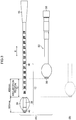
- FIG. 1 shows a general configuration of an endoscope system 100 in accordance with the present embodiment.
- the endoscope system 100 includes an endoscope 10 and the overtube 50.
- the endoscope 10 includes an insertion section 12 to be inserted into a body of a subject, and an operation section 14 is connected to a proximal end part of the insertion section 12.
- a universal code 16 is connected to the operation section 14, and a connector 18 for a light source is provided at a distal end of the universal code 16.
- a cable 20 branches off from the connector 18 for a light source, and a connector 22 for a processor is connected to a distal end of the cable 20.
- the connector 18 for a light source and the connector 22 for a processor are detachably connected to a light source device 24 and a processor device 26, respectively.
- the overtube 50 is one embodiment of an insertion auxiliary tool.
- the overtube 50 includes a holding section 52 to be held by an operator, and a tube body 54.
- the holding section 52 is a cylindrical body formed of hard material, such as resin.
- the tube body 54 is formed of flexible material, such as polyurethane, and has a cylindrical shape provided with a distal end opening 56 and a proximal end opening 58.
- the inside of the cylindrical part is configured to be an insertion passage 59 into which the insertion section 12 is inserted, and the insertion section 12 is movable back and forth in a center axis direction (X direction in Fig. 3 ) of the overtube 50.
- an inner edge of the proximal end opening 58 abuts on a boot 15 of the insertion section 12.
- the inner edge of the proximal end opening 58 constitutes a contact part.
- a balloon 57 is attached to an outer peripheral surface of a distal end part of the tube body 54.
- the balloon 57 is formed of elastic material, such as rubber, and has a cylindrical shape.
- the balloon 57 is provided at its center with a bulging part.
- the balloon 57 is attached and fixed to the outer peripheral surface of the distal end part of the tube body 54 and is configured to be expanded or shrunk by fluid (such as air or water) that is supplied and sucked through a fluid conduit line (not shown).
- This kind of expansion and shrinkage of the balloon 57 is controlled by a balloon control device 60.
- the balloon control device 60 supplies and sucks fluid, or controls a pressure of the fluid to expand or shrink the balloon 57, or to maintain a state of the balloon 57.
- the ballon control device 60 includes: a device body 62 provided with a pump, a sequencer, and the like, a hand switch 63; and a balloon monitor 64.
- the insertion section 12 includes a flexible portion 36, a bending portion 38, and a distal end hard portion 40, which are sequentially connected in this order from a proximal end side (operation section 14 side) to a distal end side.
- the boot 15 of the insertion section 12 is provided at a portion of the flexible portion 36, closest to the proximal end.
- the boot 15 is formed (tapered) so as to gradually decrease in diameter from the proximal end side toward the distal end side.
- the operation section 14 includes: an angle knob 28 for bending operation; an air/water supply button 30 for injecting air, water, or the like, from the distal end of the insertion section 12 (an opening provided at the distal end hard portion 40 to be described later); a suction button 32; and the like.
- the operation section 14 is provided on its insertion section 12 side with a forceps entry port 34 from which various treatment tools are to be inserted.
- air or water is supplied by an air/water supply device which is built in the light source device 24, and injected toward an observation window from an air/water supply nozzle.
- a forceps exit port is connected to a forceps channel (not shown) provided inside the insertion section 12 to communicate with the forceps entry port 34.
- a distal end of a treatment tool inserted from the forceps entry port 34 is exposed from the forceps exit port.
- the flexible portion 36 has a laminated structure as follows: an innermost of the flexible portion 36 is a spiral tube 37 which is formed by spirally winding an elastic thin strip-like plate 37A; the outside of the spiral tube 37 is coated with a net 37B which is woven from metal wires, and then caps 37C are fitted into respective opposite ends of the spiral tube 37 to form a tubular body 37D; an outer skin 37E which is made of resin is laminated on an outer peripheral surface of the tubular body 37D.
- the flexible portion 36 configured as above includes a low flexural rigidity portion 36A, a flexural rigidity varying portion 36B, and a high flexural rigidity portion 36C, in this order from the distal end side toward the proximal end side (refer to Fig. 1 ).
- a flexural rigidity of the low flexural rigidity portion 36A and the high flexural rigidity portion 36C is uniform along a longitudinal axial direction of the insertion section 12 (X direction in Fig. 3 ), and the high flexural rigidity portion 36C has a flexural rigidity that is relatively higher than a flexural rigidity of the low flexural rigidity portion 36A.
- the low flexural rigidity portion 36A and the high flexural rigidity portion 36C constitute a first flexural rigidity uniform portion and a second flexural rigidity uniform portion, in the present invention, respectively.
- a flexural rigidity of the flexural rigidity varying portion 36B uniformly increases from a low flexural rigidity portion 36A side (distal end side) to a high flexural rigidity portion 36C side(proximal end side) (details will be described later).
- the variations of flexural rigidity in the flexural rigidity varying portion 36B can be achieved by forming the outer skin 37E of the flexible portion 36 by resin layers RH and RS with different hardness, and varying thicknesses of the resin layers from the distal end side toward the proximal end side.
- an outside part of the outer skin 37E is composed of a hard (high flexural rigidity) resin layer RH
- an inside part of the outer skin 37E is composed of a soft resin layer RS (having a flexural rigidity less than that of the resin layer RH).
- the resin layer RS is increased in thickness at a first position P1 on the distal end side (low flexural rigidity portion 36A side).
- the resin layer RS is gradually reduced in thickness from the first position P1 toward a second position P2 on the proximal end side (high flexural rigidity portion 36C side) and increase a thickness of the resin layer RH, where the total thickness of the resin layers RH and RS is uniform.
- the flexural rigidity in the flexural rigidity varying portion 36B can uniformly increase from the distal end side toward the proximal end side (a rate of increase in flexural rigidity is constant).
- the variations of flexural rigidity also can be achieved by varying a mixing ratio of hard resin and soft resin, instead of varying the thickness of the resin layers.
- a ratio of soft (low flexural rigidity) resin may be set high on the distal end side, and a ratio of hard (high flexural rigidity) resin may be increased from the distal end side toward the proximal end side.
- a thickness of a resin layer may be increased from the distal end side toward the proximal end side by using a single resin (thickness of the outer skin 37E is increased) to increase the flexural rigidity.
- the present embodiment describes the case where the flexural rigidity in the flexural rigidity varying portion 36B uniformly increases from the low flexural rigidity portion 36A side toward the high flexural rigidity portion 36C side (a rate of increase in flexural rigidity is constant), the present invention does not limit the variation of flexural rigidity to this kind of aspect.
- a rate of increase in flexural rigidity may vary from the low flexural rigidity portion 36A side toward the high flexural rigidity portion 36C side.
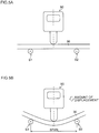
- the flexural rigidity of the flexible portion 36 can be measured by the following steps of: supporting the flexible portion 36 at two points S1 and S2 in the longitudinal axial direction; applying a load to the midpoint between the two points to deform the flexible portion 36; and measuring a reaction force from the flexible portion 36, caused by the deformation of the flexible portion 36, with a force gauge 90.
- a span (a distance between points S1 and S, which support the flexible portion 36, in the longitudinal axial direction) may be set to 30 mm to 200 mm
- a displacement an amount of deformation of the flexible portion 36 in a direction orthogonal to the longitudinal axial direction (downward in Figs. 5A and 5B ) caused by the applied load
- the measurement conditions of the flexural rigidity is not limited to the example above, and thus measurement conditions may be used properly depending on a length, the amount of displacement, and a level of flexural rigidity, of a portion to be measured.
- the bending portion 38 has a configuration as follows: angle rings (not shown) that are rotatably connected to each other to constitute a structure; an outer periphery of the structure is coated with a net woven from metal wires; and the net is coated with an outer skin made of rubber.
- a plurality of operation wires extend from the operation section 14 to the bending portion 38, and a distal end part of each of the operation wires is fixed to the angle ring of the distal end part constituting the bending portion 38. Accordingly, the bending portion 38 is bent up and down, and left and right, in response to operation of the angle knob 28 provided in the operation section 14.
- a balloon 39 is attached to an outer periphery of the bending portion 38 (refer to Fig. 1 ), and the balloon 39 is configured to be expanded or shrunk by fluid (such as air or water) supplied and discharged through a fluid conduit line (not shown) provided in the insertion section 12, as with the balloon 57 described above.
- An optical system (such as lens, and an imaging element, which are not shown) for imaging the inside of a subject is built inside the distal end hard portion 40.
- a distal end face of the distal end hard portion 40 is provided with an observation window, an illumination window, an air/water supply nozzle, a forceps exit port, and the like, which are not shown.
- Behind the illumination window there is provided an emission end of a light guide through which an illumination light from the light source device 24 is guided. The illumination light guided by the light guide is emitted toward a site to be observed inside the subject through the illumination window described above.
- a sliding range of the insertion section 12 with respect to the overtube 50 will be described. While the present embodiment describes a case where the effective length of the insertion section 12 is 1520 mm, and the overall length of the overtube 50 is 1050 mm, the present invention does not limit length of each of the insertion section 12 and the overtube 50 to this kind of case.
- Fig. 3 is prepared to clearly indicate a relationship between each element, and does not accurately reflect an actual size and shape.
- Portion (A) in Fig. 3 shows a position relation between the insertion section 12 and the overtube 50, where the insertion section 12 is inserted into the overtube 50 and is slid (moved) until the boot 15 which is provided on a proximal end side of the insertion section 12 abuts on the overtube 50 (that is, until the insertion section 12 is positioned at a distal end position within a back-and forth movable range in which the insertion section 12 is movable with respect to the overtube 50).
- an outer diameter of the boot 15 is equal to an inner diameter of the proximal end opening 58 of the overtube 50, and the overtube 50 abuts on the boot 15 to prevent the insertion section 12 from sliding further toward a distal end side of the overtube 50.
- the distal end hard portion 40, the bending portion 38, and a part of the flexible portion 36 (a part of a distal end side of the low flexural rigidity portion 36A) of the insertion section 12 project from the distal end opening 56 of the overtube 50 (refer to the Potion (A) in Fig. 3 ).
- the projecting part has a length of 500 mm, and hereinafter a region where a part of the flexible portion 36 projects, in the projecting part, is referred to as a "projection region 70".
- the balloon 39 is attached to the bending portion 38 and the bending portion 38 cannot slide in the overtube 50 (this state is shown in the Portion (B) in Fig. 3 by a dotted line).
- the flexible portion 36 can slide in the overtube 50 within a range of the projection region 70 (that is, a range between the states shown in the Portions (A) and (B) in Fig. 3 ).
- the total length of the distal end hard portion 40 and the bending portion 38 is set to 100 mm.
- the length of the projection region 70 is 400 mm.
- a position and a range, where the flexural rigidity varying portion 36B is provided, as well as a value of flexural rigidity in the flexural rigidity varying portion 36B, will be described in detail. While the present embodiment describes the case where the insertion section 12 and the overtube 50 are inserted into around the stomach and the small intestine of the subject, a case where the endoscope system of the present invention is applicable is not limited to this kind of case.
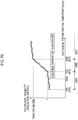
- Fig. 6 shows the flexural rigidity of the flexible portion 36 in the present embodiment.
- a distal end position P0 in the projection region 70 is 100 mm away from the distal end of the insertion section 12, and the length of the projection region 70 is 400 mm (up to a position at 500 mm way from the distal end of the insertion section 12).
- the flexural rigidity is uniform (a minimum flexural rigidity portion) up to a first position P1 that is further 200 mm away from the most proximal end part toward the proximal end (up to a position 700 mm away from the distal end of the insertion section 12).
- the minimum flexural rigidity portion from the distal end position P0 to the first position P1 is the low flexural rigidity portion 36A (first flexural rigidity uniform portion) described above.
- a portion from the first position P1 to a second position P2 (900 mm away from the distal end of the insertion section 12) which is closer to the proximal end of the insertion section 12 than the first position P1 is the flexural rigidity varying portion 36B, and a portion toward the proximal end with respect to the second position P2 is the high flexural rigidity portion 36C (second flexural rigidity uniform portion).
- a part of the low flexural rigidity portion 36A projects from the distal end opening 56 of the overtube 50, and a proximal end position of the low flexural rigidity portion 36A (, which is the same as the first position P1 on the distal end side of the flexural rigidity varying portion 36B,) is located to be closer to a proximal end side of the overtube 50 than the distal end opening 56 in the longitudinal axial direction of the insertion section 12 (X direction in Fig. 3 ).
- the flexural rigidity in the low flexural rigidity portion 36A and the high flexural rigidity portion 36C is uniform in the longitudinal axial direction of the insertion section 12 (that is, an average rate of change of flexural rigidity is zero) and the flexural rigidity in the flexural rigidity varying portion 36B uniformly increases in the longitudinal axial direction of the insertion section 12. That is, an average rate of change of flexural rigidity in the flexural rigidity varying portion 36B is larger than the average rate of change of flexural rigidity in the low flexural rigidity portion 36A, and also larger than the average rate of change of flexural rigidity in the high flexural rigidity portion 36C.
- the "average rate of change of flexural rigidity" in the flexural rigidity varying portion 36B is a value expressed by (Y - X) / Z, when it is assumed that: X (at the distal end position PI) and Y (at the proximal end position P2) are values of the flexural rigidity in the flexural rigidity varying portion 36B; and Z is a length (length along the longitudinal axial direction of the insertion section 12) of the flexural rigidity varying portion 36C (here, X, Y, and Z are more than zero, and Y is more than X).
- the average rate of change of the flexural rigidity of each of the low flexural rigidity portion 36A, and the high flexural rigidity portion 36C also can be defined.
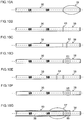
- Fig. 6 shows, as one of preferable aspects, the case where the flexural rigidity in the low flexural rigidity portion 36A and the high flexural rigidity portion 36C is uniform along a longitudinal direction of the flexible portion 36, the present invention is not limited to this kind of aspect.
- the flexural rigidity in each of the low flexural rigidity portion 36A and the high flexural rigidity portion 36C does not have to be always uniform.
- Fig. 7A shows an example of varying the flexural rigidity in the low flexural rigidity portion 36A and the high flexural rigidity portion 36C, in this way.
- Fig. 7A shows an example of varying the flexural rigidity in the low flexural rigidity portion 36A and the high flexural rigidity portion 36C, in this way.
- the flexural rigidity of any one of the low flexural rigidity portion 36A and the high flexural rigidity portion 36C may be varied.
- a rate of change of flexural rigidity in the low flexural rigidity portion 36A, the flexural rigidity varying portion 36B, and the high flexural rigidity portion 36C does not have to be uniform in the longitudinal axial direction of the insertion section 12.
- the flexural rigidity may vary up and down (a curve in a graph of Fig.
- the flexural rigidity may periodically vary along the longitudinal axial direction of the insertion section 12, or may vary in a random manner.
- a coating region 72 (a range in which the flexible portion 36 is covered with the overtube 50) has a length of 200 mm, however, the length is an example of preferable values. Even if the length of the coating region 72 is varied within a range from 100 mm to 300 mm, the same effect as that of the example shown in Fig. 6 can be achieved.
- the flexural rigidity varying portion 36B has a length of 200 mm, the length is an example of preferable values. Even if the length of the flexural rigidity varying portion 36B is varied within a range from 100 mm to 400 mm, the same effect as that of the example shown in Fig. 6 can be achieved.
- the flexural rigidity in the flexural rigidity varying portion 36B uniformly increases from the distal end position (first position PI) toward the proximal end position (second position P2) (a rate of increase in the flexural rigidity is constant).
- the second flexural rigidity that is flexural rigidity at the second position P2 is more than twice the first flexural rigidity that is flexural rigidity at the first position P1.
- the second flexural rigidity is set to be more than twice the first flexural rigidity to prevent the flexible portion 36 from being deformed on a proximal side, and the flexible portion 36 can be easily inserted.
- the insertion section 12 and the overtube 50 can be inserted into a subject as below, for example. Specifically, firstly, an operator holds the holding section 52 and inserts the overtube 50 into a body from the mouth of the subject. When a predetermined length of the overtube 50 is inserted, the balloon control device 60 described above is controlled to expand the balloon 57 to fix the overtube 50 to the subject. In this state, the insertion section 12 is inserted into the insertion passage 59 of the overtube 50. Then, the insertion section 12 is inserted deep into the subject until the boot 15 abuts on an inner periphery of the proximal end opening 58.
- the insertion section 12 is positioned at the distal end position within the back-and-forth movable range in which the insertion section 12 is movable with respect to the overtube 50, and a part of the distal end side of the flexible portion 36 and the bending portion 38 are exposed from the distal end opening 56.
- the balloon control device 60 is controlled to expand the balloon 39 to fix the insertion section 12 to the subject.
- the balloon 57 is shrunk to release the fixing of the overtube 50 to the subject, and the overtube 50 is inserted deeper (until the distal end opening 56 is located at a proximal end part of the bending portion 38).
- the balloon 57 is expanded to fix the overtube 50 to the subject, and the balloon 39 is shrunk to release the fixing of the insertion section 12 and the insertion section 12 is inserted deeper. Repeating that procedure enables the insertion section 12 and the overtube 50 to be inserted to a desired site of the subject.
- the angle knob 28 is appropriately operated to bend the bending portion 38 up and down, left and right, to direct the distal end part of the insertion section 12 in a desired direction.
- Fig. 8 shows a state when the insertion section 12 and the overtube 50 of the endoscope system 100 in accordance with the present embodiment are inserted into a subject from whom the stomach is completely removed.
- a direction of the insertion section 12 needs to be greatly changed near a Y-limb (an anastomotic part between the small intestine and the duodenum) designated by reference character PY in Fig. 8 . If the flexural rigidity of the insertion section is high, the insertion becomes difficult and the insertion causes a large load on the subject.
- the insertion into a duodenum with respect to the Y-limb can be facilitated, as well as a load on the subject, caused by the insertion, can be reduced.
- Figs. 9A and 9B are graphs showing examples of a relationship between the amount of variation of flexural rigidity in the flexural rigidity varying portion and the maximum flexural rigidity of the overtube. If the variation of flexural rigidity in the flexural rigidity varying portion 36B is too small relative to the flexural rigidity of the overtube 50, the effect to be achieved by providing the flexural rigidity variation portion 36B decreases. Thus, in the present embodiment, a difference between the maximum flexural rigidity and the minimum flexural rigidity in the flexural rigidity varying portion 36B, is set to be more than a half of the maximum flexural rigidity of the overtube 50, as shown in Figs. 9A and 9B .
- Figs. 9A and 9B describes the case where the flexural rigidity of the overtube 50 in the center axis direction is uniform.
- the flexural rigidity at a position having the maximum flexural rigidity is assumed to be C and satisfy the relationship above.
- the endoscope system 100 in accordance with the present embodiment can secure an appropriate flexural rigidity of the insertion section.
- the boot 15 abuts on the inner edge (contact part) of the proximal end opening 58 of the overtube 50 and performs positioning of the overtube 50 (identification and restriction of the proximal end position of the overtube 50).
- positioning identification and restriction of the distal end position of the overtube 50
- the insertion section 12 is positioned at the proximal end position within the back-and-forth movable range in which the insertion section 12 is movable with respect to the overtube 50, can be performed as shown in examples below, for example.
- the positioning can be performed by allowing an inner edge of the distal end opening 56 of the overtube 50 and a proximal end side of the balloon 39 attached to the outer periphery of the bending portion 38 to be brought into contact with each other (refer to Fig. 10A ).
- the positioning in the example 1 is applicable to so-called an endoscope of a double balloon type such as the aspect above, in which the balloons 39 and 57 are attached to the bending portion 38 and the overtube 50, respectively.
- the positioning can be performed by allowing a fixing portion 81 provided on a proximal end side of the bending portion 38 and the inner edge of the distal end opening 56 of the overtube 50 to be brought into contact with each other (refer to Fig. 10B ).
- the positioning in the example 2 is applicable not only to an endoscope of a double balloon type such as the aspect above, but also to an endoscope of a single balloon type, in which a balloon is attached to only a distal end of an insertion section.
- the positioning can be performed by providing a ring-shaped member 82 with an outer diameter larger than an outer diameter of the bending portion 38 in the middle of the bending portion 38 (middle of the insertion section 12 in the longitudinal axial direction) and allowing a distal end of the overtube 50 to abut on the ring-shaped member 82 (refer to Fig. 10C ).
- the positioning can be performed by providing a contact part 83 by partially thickening a part in the middle of the bending portion 38 (middle of the insertion section 12 in the longitudinal axial direction), and allowing the distal end of the overtube 50 to abut on the contact part 83 (refer to Fig. 10D ).
- the positioning can be performed by providing a contact part 84 by fixing a member, such as a ring, to the distal end side of the flexible portion 36 with adhesive, and allowing the distal end of the overtube 50 to abut on the contact part 84 (refer to Fig. 10E ).
- a member such as a ring
- the positioning can be performed by providing an enlarged diameter part 85 by expanding a part in the middle of the bending portion 38 (middle of the insertion section 12 in the longitudinal axial direction) (refer to Fig. 10F ), and fixing the enlarged diameter part 85 and an inner circumference of the overtube 50 to each other with a frictional force therebetween or a radial clamping force (refer to Fig. 10G ).
Landscapes
- Health & Medical Sciences (AREA)
- Life Sciences & Earth Sciences (AREA)
- Surgery (AREA)
- Biomedical Technology (AREA)
- Medical Informatics (AREA)
- Optics & Photonics (AREA)
- Pathology (AREA)
- Radiology & Medical Imaging (AREA)
- Biophysics (AREA)
- Engineering & Computer Science (AREA)
- Physics & Mathematics (AREA)
- Heart & Thoracic Surgery (AREA)
- Nuclear Medicine, Radiotherapy & Molecular Imaging (AREA)
- Molecular Biology (AREA)
- Animal Behavior & Ethology (AREA)
- General Health & Medical Sciences (AREA)
- Public Health (AREA)
- Veterinary Medicine (AREA)
- Endoscopes (AREA)
- Instruments For Viewing The Inside Of Hollow Bodies (AREA)
- Gastroenterology & Hepatology (AREA)
Claims (9)
- Système d'endoscope (100), comprenant :un endoscope (10) incluant : une section d'introduction (12) devant être introduite dans un corps, et une section de manœuvre (14) reliée à un côté d'extrémité proximale de la section d'introduction (12), la section d'introduction (12) présentant une portion dure d'extrémité distale (40), une portion de courbure (38) reliée à un côté d'extrémité proximale de la portion dure d'extrémité distale (40) et une portion flexible (36) reliée à un côté d'extrémité proximale de la portion de courbure (38) ;dans lequella portion flexible (36) inclut :une portion de rigidité à la flexion faible (36A), laquelle est positionnée sur un côté d'extrémité distale de la portion flexible (36), etune portion variant quant à la rigidité à la flexion (36B) positionnée sur le côté d'extrémité proximale de la portion de rigidité à la flexion faible (36A) et présentant une rigidité à la flexion qui diminue d'un côté de portion de rigidité à la flexion faible (36A) vers un côté d'extrémité proximale, la portion variant quant à la rigidité à la flexion (36B) présentant un taux moyen de modification de rigidité à la flexion dans une direction axiale longitudinale de la section d'introduction (12), le taux moyen de modification de rigidité à la flexion étant plus grand qu'un taux moyen de modification de rigidité à la flexion dans la portion de rigidité à la flexion faible (36A) dans la direction axiale longitudinale de la section d'introduction (12),caractérisé en ce que le système d'endoscope inclut un outil auxiliaire d'introduction (50) incluant un corps formant tube (54) présentant une ouverture d'extrémité distale (56), une ouverture d'extrémité proximale (58) et un passage d'introduction (59) dans lequel la section d'introduction (12) est introduite à partir de l'ouverture d'extrémité proximale (58), la section d'introduction (12) pouvant réaliser un va-et-vient le long d'une direction d'axe centrale du corps formant tube (54), le corps formant tube (54) étant configuré pour présenter une longueur permettant à au moins une partie de la portion flexible (36) de faire saillie à partir de l'ouverture d'extrémité distale (56) lorsque la section d'introduction (12) est positionnée sur une position d'extrémité distale dans les limites de la plage de va-et-vient sur laquelle la section d'introduction (12) peut se déplacer par rapport au corps formant tube (54), etlorsque la section d'introduction (12) est positionnée sur une position d'extrémité distale dans les limites de la plage de va-et-vient par rapport au corps formant tube (54), une position d'extrémité proximale de la portion de rigidité à la flexion faible (36A) est positionnée sur un côté d'extrémité proximale par rapport à l'ouverture d'extrémité distale (56) du corps formant tube (54), dans la direction axiale longitudinale de la section d'introduction (12).
- Système d'endoscope (100) selon la revendication 1, dans lequel
l'outil auxiliaire d'introduction (50) inclut, sur un côté d'extrémité proximale du corps formant tube (54), une partie de contact configurée pour abouter sur l'endoscope, et
lorsque l'endoscope (10) aboute sur la partie de contact, la position d'extrémité proximale de la portion de rigidité à la flexion faible (36A) est positionnée sur un côté d'extrémité proximale par rapport à l'ouverture d'extrémité distale (56) du corps formant tube (54), dans la direction axiale longitudinale de la section d'introduction (12). - Système d'endoscope (100) selon la revendication 1, dans lequel
la portion variant quant à la rigidité à la flexion (36B) est entièrement recouverte par le corps formant tube (54) lorsque la section d'introduction (12) est positionnée sur la position d'extrémité distale dans les limites de la plage de va-et-vient par rapport au corps formant tube (54). - Système d'endoscope (100) selon l'une quelconque des revendications 1 à 3, dans lequel
l'outil auxiliaire d'introduction (50) inclut, sur un côté d'extrémité proximale du corps formant tube (54), une partie de contact configurée pour abouter sur l'endoscope, et
la portion variant quant à la rigidité à la flexion (36B) est entièrement recouverte par le corps formant tube (54) lorsque l'endoscope (10) aboute sur la partie de contact. - Système d'endoscope (100) selon l'une quelconque des revendications 1 à 4, dans lequel
la portion de rigidité à la flexion faible (36A) inclut une première portion uniforme quant à la rigidité à la flexion, où une rigidité à la flexion est uniforme le long de la direction axiale longitudinale de la section d'introduction (12). - Système d'endoscope (100) selon l'une quelconque des revendications 1 à 5, dans lequel
la portion flexible (36) inclut une portion de rigidité à la flexion élevée (36C) sur un côté d'extrémité proximale de la portion flexible (36), la portion de rigidité à la flexion élevée (36C) présentant une rigidité à la flexion supérieure de manière relative à une rigidité à la flexion de la portion de rigidité à la flexion faible (36A), et
le taux moyen de modification de rigidité à la flexion dans la portion variant quant à la rigidité à la flexion (36B) dans une direction axiale longitudinale de la section d'introduction (12) est plus grand qu'un taux moyen de modification de rigidité à la flexion dans la portion de rigidité à la flexion élevée (36C) dans la direction axiale longitudinale de la section d'introduction (12). - Système d'endoscope (100) selon la revendication 6, dans lequel
la portion de rigidité à la flexion élevée (36C) inclut une seconde portion uniforme quant à la rigidité à la flexion, où une rigidité à la flexion est uniforme le long de la direction axiale longitudinale de la section d'introduction (12). - Système d'endoscope (100) selon l'une quelconque des revendications 1 à 7, dans lequel
lorsqu'une rigidité à la flexion sur une position d'extrémité distale de la portion variant quant à la rigidité à la flexion (36B) est indiquée comme une première rigidité à la flexion et qu'une rigidité à la flexion sur une position d'extrémité proximale de la portion variant quant à la rigidité à la flexion (36B) est indiquée comme une deuxième rigidité à la flexion, la deuxième rigidité à la flexion maximale est égale à plus du double de la première rigidité à la flexion. - Système d'endoscope (100) selon l'une quelconque des revendications 1 à 8, dans lequel
lorsqu'une rigidité à la flexion sur une position d'extrémité distale de la portion variant quant à la rigidité à la flexion (36B) est indiquée comme une première rigidité à la flexion, une rigidité à la flexion sur une position d'extrémité proximale de la portion variant quant à la rigidité à la flexion (36B) est indiquée comme une deuxième rigidité à la flexion, et une rigidité à la flexion sur une position présentant une rigidité à la flexion maximale dans le corps formant tube (54) est indiquée comme une troisième rigidité à la flexion, une différence entre la première rigidité à la flexion et la deuxième rigidité à la flexion est égale à plus de la moitié de la troisième rigidité à la flexion.
Applications Claiming Priority (2)
| Application Number | Priority Date | Filing Date | Title |
|---|---|---|---|
| JP2015114497A JP6444809B2 (ja) | 2015-06-05 | 2015-06-05 | 内視鏡システム |
| EP16172115.4A EP3103376B1 (fr) | 2015-06-05 | 2016-05-31 | Système d'endoscope |
Related Parent Applications (1)
| Application Number | Title | Priority Date | Filing Date |
|---|---|---|---|
| EP16172115.4A Division EP3103376B1 (fr) | 2015-06-05 | 2016-05-31 | Système d'endoscope |
Publications (2)
| Publication Number | Publication Date |
|---|---|
| EP3378376A1 EP3378376A1 (fr) | 2018-09-26 |
| EP3378376B1 true EP3378376B1 (fr) | 2019-10-23 |
Family
ID=56096523
Family Applications (2)
| Application Number | Title | Priority Date | Filing Date |
|---|---|---|---|
| EP16172115.4A Active EP3103376B1 (fr) | 2015-06-05 | 2016-05-31 | Système d'endoscope |
| EP18170330.7A Active EP3378376B1 (fr) | 2015-06-05 | 2016-05-31 | Système d'endoscope |
Family Applications Before (1)
| Application Number | Title | Priority Date | Filing Date |
|---|---|---|---|
| EP16172115.4A Active EP3103376B1 (fr) | 2015-06-05 | 2016-05-31 | Système d'endoscope |
Country Status (3)
| Country | Link |
|---|---|
| US (1) | US20160353980A1 (fr) |
| EP (2) | EP3103376B1 (fr) |
| JP (1) | JP6444809B2 (fr) |
Families Citing this family (7)
| Publication number | Priority date | Publication date | Assignee | Title |
|---|---|---|---|---|
| WO2016061315A1 (fr) * | 2014-10-15 | 2016-04-21 | Smith & Nephew, Inc. | Endoscope comportant une section de travail multidiamètre |
| CN108366710B (zh) * | 2015-11-20 | 2020-08-11 | 奥林巴斯株式会社 | 内窥镜系统 |
| US10939814B2 (en) * | 2016-08-19 | 2021-03-09 | Jason Andrew Slate | Systems and method for preventing air escape and maintaining air distension |
| CN110267581A (zh) * | 2017-03-31 | 2019-09-20 | Hoya株式会社 | 内窥镜 |
| WO2019130639A1 (fr) * | 2017-12-28 | 2019-07-04 | オリンパス株式会社 | Endoscope et système d'endoscope |
| JP7156805B2 (ja) * | 2018-02-21 | 2022-10-19 | Hoya株式会社 | 内視鏡 |
| JP7033157B2 (ja) * | 2019-03-28 | 2022-03-09 | 富士フイルム株式会社 | 取付治具付きバルーンの包装体及びバルーン取付方法 |
Family Cites Families (16)
| Publication number | Priority date | Publication date | Assignee | Title |
|---|---|---|---|---|
| US5885208A (en) * | 1996-12-24 | 1999-03-23 | Olympus Optical Co., Ltd. | Endoscope system |
| JP3869060B2 (ja) * | 1996-12-24 | 2007-01-17 | オリンパス株式会社 | 内視鏡 |
| US6837846B2 (en) * | 2000-04-03 | 2005-01-04 | Neo Guide Systems, Inc. | Endoscope having a guide tube |
| JP3850377B2 (ja) | 2003-02-21 | 2006-11-29 | オリンパス株式会社 | 内視鏡装置 |
| JP3806933B2 (ja) * | 2004-03-19 | 2006-08-09 | フジノン株式会社 | 内視鏡装置 |
| JP4499479B2 (ja) | 2004-05-28 | 2010-07-07 | オリンパス株式会社 | 内視鏡用オーバーチューブおよび小腸内視鏡システム |
| US8075476B2 (en) * | 2004-07-27 | 2011-12-13 | Intuitive Surgical Operations, Inc. | Cannula system and method of use |
| US20070015965A1 (en) * | 2005-07-13 | 2007-01-18 | Usgi Medical Inc. | Methods and apparatus for colonic cleaning |
| JP4885634B2 (ja) * | 2006-07-24 | 2012-02-29 | オリンパスメディカルシステムズ株式会社 | 回転自走式内視鏡 |
| WO2011016428A1 (fr) * | 2009-08-07 | 2011-02-10 | オリンパスメディカルシステムズ株式会社 | Système médical |
| JP5591043B2 (ja) * | 2010-09-22 | 2014-09-17 | 富士フイルム株式会社 | 内視鏡及びその軟性部 |
| JP5851139B2 (ja) | 2011-07-27 | 2016-02-03 | オリンパス株式会社 | 医療装置 |
| JP2013090875A (ja) | 2011-10-27 | 2013-05-16 | Fujifilm Corp | 内視鏡及び内視鏡洗浄用アダプタ |
| US9629535B2 (en) * | 2012-07-10 | 2017-04-25 | University Hospitals Of Cleveland | Colonoscope closure device |
| JP5927103B2 (ja) * | 2012-10-25 | 2016-05-25 | 富士フイルム株式会社 | 内視鏡挿入部、内視鏡、及び曲げ剛性プロファイル補正具 |
| JP6368256B2 (ja) * | 2015-02-05 | 2018-08-01 | 富士フイルム株式会社 | 内視鏡システム |
-
2015
- 2015-06-05 JP JP2015114497A patent/JP6444809B2/ja active Active
-
2016
- 2016-05-31 EP EP16172115.4A patent/EP3103376B1/fr active Active
- 2016-05-31 EP EP18170330.7A patent/EP3378376B1/fr active Active
- 2016-06-01 US US15/170,930 patent/US20160353980A1/en not_active Abandoned
Non-Patent Citations (1)
| Title |
|---|
| None * |
Also Published As
| Publication number | Publication date |
|---|---|
| JP6444809B2 (ja) | 2018-12-26 |
| US20160353980A1 (en) | 2016-12-08 |
| EP3103376A1 (fr) | 2016-12-14 |
| EP3378376A1 (fr) | 2018-09-26 |
| EP3103376B1 (fr) | 2018-05-16 |
| JP2017000222A (ja) | 2017-01-05 |
Similar Documents
| Publication | Publication Date | Title |
|---|---|---|
| EP3378376B1 (fr) | Système d'endoscope | |
| US20230074673A1 (en) | Endoscope system | |
| US11246472B2 (en) | Endoscope system | |
| EP1559361B1 (fr) | Applicateur pour l'endoscope et endoscope | |
| EP1849396B1 (fr) | Tube souple d'endoscope et dispositif endoscopique | |
| EP2080474B1 (fr) | Dispositif de mesure de diamètre interne | |
| EP2710949A1 (fr) | Dispositifs médicaux pour l'identification et le traitement de passages corporels | |
| JP2022106908A (ja) | 血管プロテーゼを受容し、その展開を補助するための柔軟部材 | |
| US20110237888A1 (en) | Guide tube for guiding endoscope or surgical tool in or into body cavity | |
| CN108968903B (zh) | 用于在结肠镜与附加管之间联接的设备和方法 | |
| EP2848187A1 (fr) | Tube souple pour endoscope, et endoscope | |
| JPWO2013088791A1 (ja) | 樹脂チューブ及び内視鏡 | |
| US20210308423A1 (en) | Support structure for medical apparatus and method of manufacturing same | |
| JP5927103B2 (ja) | 内視鏡挿入部、内視鏡、及び曲げ剛性プロファイル補正具 | |
| CN110475579B (zh) | 导向丝-导管组件 | |
| CN212879241U (zh) | 插入管及内窥镜 | |
| JPH0984878A (ja) | カテーテルチューブ | |
| US20190351190A1 (en) | Multi-culvature catheter and medical device for surgery | |
| US11540704B2 (en) | Flexible mechanism | |
| JP2002000552A (ja) | 内視鏡用可撓管 | |
| JP6525050B2 (ja) | 処置具挿入補助具 | |
| US9295819B2 (en) | Fluid supply body and balloon catheter | |
| JP6756780B2 (ja) | 内視鏡システム | |
| JP3821236B2 (ja) | 内視鏡の挿入補助具 | |
| JP2010035759A (ja) | 内視鏡 |
Legal Events
| Date | Code | Title | Description |
|---|---|---|---|
| PUAI | Public reference made under article 153(3) epc to a published international application that has entered the european phase |
Free format text: ORIGINAL CODE: 0009012 |
|
| STAA | Information on the status of an ep patent application or granted ep patent |
Free format text: STATUS: THE APPLICATION HAS BEEN PUBLISHED |
|
| AC | Divisional application: reference to earlier application |
Ref document number: 3103376 Country of ref document: EP Kind code of ref document: P |
|
| AK | Designated contracting states |
Kind code of ref document: A1 Designated state(s): AL AT BE BG CH CY CZ DE DK EE ES FI FR GB GR HR HU IE IS IT LI LT LU LV MC MK MT NL NO PL PT RO RS SE SI SK SM TR |
|
| STAA | Information on the status of an ep patent application or granted ep patent |
Free format text: STATUS: REQUEST FOR EXAMINATION WAS MADE |
|
| 17P | Request for examination filed |
Effective date: 20190321 |
|
| RBV | Designated contracting states (corrected) |
Designated state(s): AL AT BE BG CH CY CZ DE DK EE ES FI FR GB GR HR HU IE IS IT LI LT LU LV MC MK MT NL NO PL PT RO RS SE SI SK SM TR |
|
| GRAP | Despatch of communication of intention to grant a patent |
Free format text: ORIGINAL CODE: EPIDOSNIGR1 |
|
| STAA | Information on the status of an ep patent application or granted ep patent |
Free format text: STATUS: GRANT OF PATENT IS INTENDED |
|
| RIC1 | Information provided on ipc code assigned before grant |
Ipc: A61M 25/06 20060101ALI20190411BHEP Ipc: A61M 25/01 20060101ALI20190411BHEP Ipc: A61B 1/00 20060101AFI20190411BHEP Ipc: A61M 25/00 20060101ALI20190411BHEP |
|
| INTG | Intention to grant announced |
Effective date: 20190513 |
|
| GRAS | Grant fee paid |
Free format text: ORIGINAL CODE: EPIDOSNIGR3 |
|
| GRAA | (expected) grant |
Free format text: ORIGINAL CODE: 0009210 |
|
| STAA | Information on the status of an ep patent application or granted ep patent |
Free format text: STATUS: THE PATENT HAS BEEN GRANTED |
|
| AC | Divisional application: reference to earlier application |
Ref document number: 3103376 Country of ref document: EP Kind code of ref document: P |
|
| AK | Designated contracting states |
Kind code of ref document: B1 Designated state(s): AL AT BE BG CH CY CZ DE DK EE ES FI FR GB GR HR HU IE IS IT LI LT LU LV MC MK MT NL NO PL PT RO RS SE SI SK SM TR |
|
| REG | Reference to a national code |
Ref country code: GB Ref legal event code: FG4D |
|
| REG | Reference to a national code |
Ref country code: CH Ref legal event code: EP |
|
| REG | Reference to a national code |
Ref country code: IE Ref legal event code: FG4D |
|
| REG | Reference to a national code |
Ref country code: DE Ref legal event code: R096 Ref document number: 602016023150 Country of ref document: DE |
|
| REG | Reference to a national code |
Ref country code: AT Ref legal event code: REF Ref document number: 1192727 Country of ref document: AT Kind code of ref document: T Effective date: 20191115 |
|
| REG | Reference to a national code |
Ref country code: NL Ref legal event code: MP Effective date: 20191023 |
|
| REG | Reference to a national code |
Ref country code: LT Ref legal event code: MG4D |
|
| PG25 | Lapsed in a contracting state [announced via postgrant information from national office to epo] |
Ref country code: LV Free format text: LAPSE BECAUSE OF FAILURE TO SUBMIT A TRANSLATION OF THE DESCRIPTION OR TO PAY THE FEE WITHIN THE PRESCRIBED TIME-LIMIT Effective date: 20191023 Ref country code: SE Free format text: LAPSE BECAUSE OF FAILURE TO SUBMIT A TRANSLATION OF THE DESCRIPTION OR TO PAY THE FEE WITHIN THE PRESCRIBED TIME-LIMIT Effective date: 20191023 Ref country code: NO Free format text: LAPSE BECAUSE OF FAILURE TO SUBMIT A TRANSLATION OF THE DESCRIPTION OR TO PAY THE FEE WITHIN THE PRESCRIBED TIME-LIMIT Effective date: 20200123 Ref country code: PL Free format text: LAPSE BECAUSE OF FAILURE TO SUBMIT A TRANSLATION OF THE DESCRIPTION OR TO PAY THE FEE WITHIN THE PRESCRIBED TIME-LIMIT Effective date: 20191023 Ref country code: GR Free format text: LAPSE BECAUSE OF FAILURE TO SUBMIT A TRANSLATION OF THE DESCRIPTION OR TO PAY THE FEE WITHIN THE PRESCRIBED TIME-LIMIT Effective date: 20200124 Ref country code: BG Free format text: LAPSE BECAUSE OF FAILURE TO SUBMIT A TRANSLATION OF THE DESCRIPTION OR TO PAY THE FEE WITHIN THE PRESCRIBED TIME-LIMIT Effective date: 20200123 Ref country code: FI Free format text: LAPSE BECAUSE OF FAILURE TO SUBMIT A TRANSLATION OF THE DESCRIPTION OR TO PAY THE FEE WITHIN THE PRESCRIBED TIME-LIMIT Effective date: 20191023 Ref country code: LT Free format text: LAPSE BECAUSE OF FAILURE TO SUBMIT A TRANSLATION OF THE DESCRIPTION OR TO PAY THE FEE WITHIN THE PRESCRIBED TIME-LIMIT Effective date: 20191023 Ref country code: PT Free format text: LAPSE BECAUSE OF FAILURE TO SUBMIT A TRANSLATION OF THE DESCRIPTION OR TO PAY THE FEE WITHIN THE PRESCRIBED TIME-LIMIT Effective date: 20200224 Ref country code: NL Free format text: LAPSE BECAUSE OF FAILURE TO SUBMIT A TRANSLATION OF THE DESCRIPTION OR TO PAY THE FEE WITHIN THE PRESCRIBED TIME-LIMIT Effective date: 20191023 |
|
| PG25 | Lapsed in a contracting state [announced via postgrant information from national office to epo] |
Ref country code: RS Free format text: LAPSE BECAUSE OF FAILURE TO SUBMIT A TRANSLATION OF THE DESCRIPTION OR TO PAY THE FEE WITHIN THE PRESCRIBED TIME-LIMIT Effective date: 20191023 Ref country code: HR Free format text: LAPSE BECAUSE OF FAILURE TO SUBMIT A TRANSLATION OF THE DESCRIPTION OR TO PAY THE FEE WITHIN THE PRESCRIBED TIME-LIMIT Effective date: 20191023 Ref country code: IS Free format text: LAPSE BECAUSE OF FAILURE TO SUBMIT A TRANSLATION OF THE DESCRIPTION OR TO PAY THE FEE WITHIN THE PRESCRIBED TIME-LIMIT Effective date: 20200224 |
|
| PG25 | Lapsed in a contracting state [announced via postgrant information from national office to epo] |
Ref country code: AL Free format text: LAPSE BECAUSE OF FAILURE TO SUBMIT A TRANSLATION OF THE DESCRIPTION OR TO PAY THE FEE WITHIN THE PRESCRIBED TIME-LIMIT Effective date: 20191023 |
|
| REG | Reference to a national code |
Ref country code: DE Ref legal event code: R097 Ref document number: 602016023150 Country of ref document: DE |
|
| PG2D | Information on lapse in contracting state deleted |
Ref country code: IS |
|
| PG25 | Lapsed in a contracting state [announced via postgrant information from national office to epo] |
Ref country code: RO Free format text: LAPSE BECAUSE OF FAILURE TO SUBMIT A TRANSLATION OF THE DESCRIPTION OR TO PAY THE FEE WITHIN THE PRESCRIBED TIME-LIMIT Effective date: 20191023 Ref country code: DK Free format text: LAPSE BECAUSE OF FAILURE TO SUBMIT A TRANSLATION OF THE DESCRIPTION OR TO PAY THE FEE WITHIN THE PRESCRIBED TIME-LIMIT Effective date: 20191023 Ref country code: EE Free format text: LAPSE BECAUSE OF FAILURE TO SUBMIT A TRANSLATION OF THE DESCRIPTION OR TO PAY THE FEE WITHIN THE PRESCRIBED TIME-LIMIT Effective date: 20191023 Ref country code: ES Free format text: LAPSE BECAUSE OF FAILURE TO SUBMIT A TRANSLATION OF THE DESCRIPTION OR TO PAY THE FEE WITHIN THE PRESCRIBED TIME-LIMIT Effective date: 20191023 Ref country code: CZ Free format text: LAPSE BECAUSE OF FAILURE TO SUBMIT A TRANSLATION OF THE DESCRIPTION OR TO PAY THE FEE WITHIN THE PRESCRIBED TIME-LIMIT Effective date: 20191023 Ref country code: IS Free format text: LAPSE BECAUSE OF FAILURE TO SUBMIT A TRANSLATION OF THE DESCRIPTION OR TO PAY THE FEE WITHIN THE PRESCRIBED TIME-LIMIT Effective date: 20200223 |
|
| REG | Reference to a national code |
Ref country code: AT Ref legal event code: MK05 Ref document number: 1192727 Country of ref document: AT Kind code of ref document: T Effective date: 20191023 |
|
| PLBE | No opposition filed within time limit |
Free format text: ORIGINAL CODE: 0009261 |
|
| STAA | Information on the status of an ep patent application or granted ep patent |
Free format text: STATUS: NO OPPOSITION FILED WITHIN TIME LIMIT |
|
| PG25 | Lapsed in a contracting state [announced via postgrant information from national office to epo] |
Ref country code: SM Free format text: LAPSE BECAUSE OF FAILURE TO SUBMIT A TRANSLATION OF THE DESCRIPTION OR TO PAY THE FEE WITHIN THE PRESCRIBED TIME-LIMIT Effective date: 20191023 Ref country code: IT Free format text: LAPSE BECAUSE OF FAILURE TO SUBMIT A TRANSLATION OF THE DESCRIPTION OR TO PAY THE FEE WITHIN THE PRESCRIBED TIME-LIMIT Effective date: 20191023 Ref country code: SK Free format text: LAPSE BECAUSE OF FAILURE TO SUBMIT A TRANSLATION OF THE DESCRIPTION OR TO PAY THE FEE WITHIN THE PRESCRIBED TIME-LIMIT Effective date: 20191023 |
|
| 26N | No opposition filed |
Effective date: 20200724 |
|
| PG25 | Lapsed in a contracting state [announced via postgrant information from national office to epo] |
Ref country code: AT Free format text: LAPSE BECAUSE OF FAILURE TO SUBMIT A TRANSLATION OF THE DESCRIPTION OR TO PAY THE FEE WITHIN THE PRESCRIBED TIME-LIMIT Effective date: 20191023 Ref country code: SI Free format text: LAPSE BECAUSE OF FAILURE TO SUBMIT A TRANSLATION OF THE DESCRIPTION OR TO PAY THE FEE WITHIN THE PRESCRIBED TIME-LIMIT Effective date: 20191023 |
|
| PG25 | Lapsed in a contracting state [announced via postgrant information from national office to epo] |
Ref country code: CH Free format text: LAPSE BECAUSE OF NON-PAYMENT OF DUE FEES Effective date: 20200531 Ref country code: MC Free format text: LAPSE BECAUSE OF FAILURE TO SUBMIT A TRANSLATION OF THE DESCRIPTION OR TO PAY THE FEE WITHIN THE PRESCRIBED TIME-LIMIT Effective date: 20191023 Ref country code: LI Free format text: LAPSE BECAUSE OF NON-PAYMENT OF DUE FEES Effective date: 20200531 |
|
| REG | Reference to a national code |
Ref country code: BE Ref legal event code: MM Effective date: 20200531 |
|
| PG25 | Lapsed in a contracting state [announced via postgrant information from national office to epo] |
Ref country code: LU Free format text: LAPSE BECAUSE OF NON-PAYMENT OF DUE FEES Effective date: 20200531 |
|
| PG25 | Lapsed in a contracting state [announced via postgrant information from national office to epo] |
Ref country code: IE Free format text: LAPSE BECAUSE OF NON-PAYMENT OF DUE FEES Effective date: 20200531 |
|
| PG25 | Lapsed in a contracting state [announced via postgrant information from national office to epo] |
Ref country code: BE Free format text: LAPSE BECAUSE OF NON-PAYMENT OF DUE FEES Effective date: 20200531 |
|
| PG25 | Lapsed in a contracting state [announced via postgrant information from national office to epo] |
Ref country code: TR Free format text: LAPSE BECAUSE OF FAILURE TO SUBMIT A TRANSLATION OF THE DESCRIPTION OR TO PAY THE FEE WITHIN THE PRESCRIBED TIME-LIMIT Effective date: 20191023 Ref country code: MT Free format text: LAPSE BECAUSE OF FAILURE TO SUBMIT A TRANSLATION OF THE DESCRIPTION OR TO PAY THE FEE WITHIN THE PRESCRIBED TIME-LIMIT Effective date: 20191023 Ref country code: CY Free format text: LAPSE BECAUSE OF FAILURE TO SUBMIT A TRANSLATION OF THE DESCRIPTION OR TO PAY THE FEE WITHIN THE PRESCRIBED TIME-LIMIT Effective date: 20191023 |
|
| PG25 | Lapsed in a contracting state [announced via postgrant information from national office to epo] |
Ref country code: MK Free format text: LAPSE BECAUSE OF FAILURE TO SUBMIT A TRANSLATION OF THE DESCRIPTION OR TO PAY THE FEE WITHIN THE PRESCRIBED TIME-LIMIT Effective date: 20191023 |
|
| P01 | Opt-out of the competence of the unified patent court (upc) registered |
Effective date: 20230515 |
|
| PGFP | Annual fee paid to national office [announced via postgrant information from national office to epo] |
Ref country code: FR Payment date: 20240328 Year of fee payment: 9 |
|
| PGFP | Annual fee paid to national office [announced via postgrant information from national office to epo] |
Ref country code: GB Payment date: 20240402 Year of fee payment: 9 |
|
| PGFP | Annual fee paid to national office [announced via postgrant information from national office to epo] |
Ref country code: DE Payment date: 20240328 Year of fee payment: 9 |