EP3377816B1 - Effluent gas treatment apparatus - Google Patents
Effluent gas treatment apparatus Download PDFInfo
- Publication number
- EP3377816B1 EP3377816B1 EP16788759.5A EP16788759A EP3377816B1 EP 3377816 B1 EP3377816 B1 EP 3377816B1 EP 16788759 A EP16788759 A EP 16788759A EP 3377816 B1 EP3377816 B1 EP 3377816B1
- Authority
- EP
- European Patent Office
- Prior art keywords
- fluid
- treatment apparatus
- inlet
- combustion chamber
- fluid flow
- Prior art date
- Legal status (The legal status is an assumption and is not a legal conclusion. Google has not performed a legal analysis and makes no representation as to the accuracy of the status listed.)
- Active
Links
Images


Classifications
-
- F—MECHANICAL ENGINEERING; LIGHTING; HEATING; WEAPONS; BLASTING
- F23—COMBUSTION APPARATUS; COMBUSTION PROCESSES
- F23G—CREMATION FURNACES; CONSUMING WASTE PRODUCTS BY COMBUSTION
- F23G7/00—Incinerators or other apparatus for consuming industrial waste, e.g. chemicals
- F23G7/06—Incinerators or other apparatus for consuming industrial waste, e.g. chemicals of waste gases or noxious gases, e.g. exhaust gases
-
- F—MECHANICAL ENGINEERING; LIGHTING; HEATING; WEAPONS; BLASTING
- F23—COMBUSTION APPARATUS; COMBUSTION PROCESSES
- F23G—CREMATION FURNACES; CONSUMING WASTE PRODUCTS BY COMBUSTION
- F23G5/00—Incineration of waste; Incinerator constructions; Details, accessories or control therefor
- F23G5/08—Incineration of waste; Incinerator constructions; Details, accessories or control therefor having supplementary heating
- F23G5/12—Incineration of waste; Incinerator constructions; Details, accessories or control therefor having supplementary heating using gaseous or liquid fuel
-
- F—MECHANICAL ENGINEERING; LIGHTING; HEATING; WEAPONS; BLASTING
- F23—COMBUSTION APPARATUS; COMBUSTION PROCESSES
- F23G—CREMATION FURNACES; CONSUMING WASTE PRODUCTS BY COMBUSTION
- F23G5/00—Incineration of waste; Incinerator constructions; Details, accessories or control therefor
- F23G5/24—Incineration of waste; Incinerator constructions; Details, accessories or control therefor having a vertical, substantially cylindrical, combustion chamber
-
- F—MECHANICAL ENGINEERING; LIGHTING; HEATING; WEAPONS; BLASTING
- F23—COMBUSTION APPARATUS; COMBUSTION PROCESSES
- F23G—CREMATION FURNACES; CONSUMING WASTE PRODUCTS BY COMBUSTION
- F23G5/00—Incineration of waste; Incinerator constructions; Details, accessories or control therefor
- F23G5/44—Details; Accessories
- F23G5/46—Recuperation of heat
-
- F—MECHANICAL ENGINEERING; LIGHTING; HEATING; WEAPONS; BLASTING
- F23—COMBUSTION APPARATUS; COMBUSTION PROCESSES
- F23G—CREMATION FURNACES; CONSUMING WASTE PRODUCTS BY COMBUSTION
- F23G7/00—Incinerators or other apparatus for consuming industrial waste, e.g. chemicals
- F23G7/06—Incinerators or other apparatus for consuming industrial waste, e.g. chemicals of waste gases or noxious gases, e.g. exhaust gases
- F23G7/061—Incinerators or other apparatus for consuming industrial waste, e.g. chemicals of waste gases or noxious gases, e.g. exhaust gases with supplementary heating
- F23G7/065—Incinerators or other apparatus for consuming industrial waste, e.g. chemicals of waste gases or noxious gases, e.g. exhaust gases with supplementary heating using gaseous or liquid fuel
-
- F—MECHANICAL ENGINEERING; LIGHTING; HEATING; WEAPONS; BLASTING
- F23—COMBUSTION APPARATUS; COMBUSTION PROCESSES
- F23L—SUPPLYING AIR OR NON-COMBUSTIBLE LIQUIDS OR GASES TO COMBUSTION APPARATUS IN GENERAL ; VALVES OR DAMPERS SPECIALLY ADAPTED FOR CONTROLLING AIR SUPPLY OR DRAUGHT IN COMBUSTION APPARATUS; INDUCING DRAUGHT IN COMBUSTION APPARATUS; TOPS FOR CHIMNEYS OR VENTILATING SHAFTS; TERMINALS FOR FLUES
- F23L15/00—Heating of air supplied for combustion
- F23L15/02—Arrangements of regenerators
-
- F—MECHANICAL ENGINEERING; LIGHTING; HEATING; WEAPONS; BLASTING
- F23—COMBUSTION APPARATUS; COMBUSTION PROCESSES
- F23G—CREMATION FURNACES; CONSUMING WASTE PRODUCTS BY COMBUSTION
- F23G2206/00—Waste heat recuperation
-
- F—MECHANICAL ENGINEERING; LIGHTING; HEATING; WEAPONS; BLASTING
- F23—COMBUSTION APPARATUS; COMBUSTION PROCESSES
- F23G—CREMATION FURNACES; CONSUMING WASTE PRODUCTS BY COMBUSTION
- F23G2206/00—Waste heat recuperation
- F23G2206/10—Waste heat recuperation reintroducing the heat in the same process, e.g. for predrying
-
- F—MECHANICAL ENGINEERING; LIGHTING; HEATING; WEAPONS; BLASTING
- F23—COMBUSTION APPARATUS; COMBUSTION PROCESSES
- F23G—CREMATION FURNACES; CONSUMING WASTE PRODUCTS BY COMBUSTION
- F23G2207/00—Control
- F23G2207/50—Cooling fluid supply
-
- F—MECHANICAL ENGINEERING; LIGHTING; HEATING; WEAPONS; BLASTING
- F23—COMBUSTION APPARATUS; COMBUSTION PROCESSES
- F23G—CREMATION FURNACES; CONSUMING WASTE PRODUCTS BY COMBUSTION
- F23G2209/00—Specific waste
- F23G2209/14—Gaseous waste or fumes
-
- F—MECHANICAL ENGINEERING; LIGHTING; HEATING; WEAPONS; BLASTING
- F23—COMBUSTION APPARATUS; COMBUSTION PROCESSES
- F23G—CREMATION FURNACES; CONSUMING WASTE PRODUCTS BY COMBUSTION
- F23G2209/00—Specific waste
- F23G2209/14—Gaseous waste or fumes
- F23G2209/142—Halogen gases, e.g. silane
-
- F—MECHANICAL ENGINEERING; LIGHTING; HEATING; WEAPONS; BLASTING
- F23—COMBUSTION APPARATUS; COMBUSTION PROCESSES
- F23G—CREMATION FURNACES; CONSUMING WASTE PRODUCTS BY COMBUSTION
- F23G2900/00—Special features of, or arrangements for incinerators
- F23G2900/00001—Exhaust gas recirculation
-
- F—MECHANICAL ENGINEERING; LIGHTING; HEATING; WEAPONS; BLASTING
- F23—COMBUSTION APPARATUS; COMBUSTION PROCESSES
- F23L—SUPPLYING AIR OR NON-COMBUSTIBLE LIQUIDS OR GASES TO COMBUSTION APPARATUS IN GENERAL ; VALVES OR DAMPERS SPECIALLY ADAPTED FOR CONTROLLING AIR SUPPLY OR DRAUGHT IN COMBUSTION APPARATUS; INDUCING DRAUGHT IN COMBUSTION APPARATUS; TOPS FOR CHIMNEYS OR VENTILATING SHAFTS; TERMINALS FOR FLUES
- F23L2900/00—Special arrangements for supplying or treating air or oxidant for combustion; Injecting inert gas, water or steam into the combustion chamber
- F23L2900/07002—Injecting inert gas, other than steam or evaporated water, into the combustion chambers
-
- F—MECHANICAL ENGINEERING; LIGHTING; HEATING; WEAPONS; BLASTING
- F23—COMBUSTION APPARATUS; COMBUSTION PROCESSES
- F23L—SUPPLYING AIR OR NON-COMBUSTIBLE LIQUIDS OR GASES TO COMBUSTION APPARATUS IN GENERAL ; VALVES OR DAMPERS SPECIALLY ADAPTED FOR CONTROLLING AIR SUPPLY OR DRAUGHT IN COMBUSTION APPARATUS; INDUCING DRAUGHT IN COMBUSTION APPARATUS; TOPS FOR CHIMNEYS OR VENTILATING SHAFTS; TERMINALS FOR FLUES
- F23L2900/00—Special arrangements for supplying or treating air or oxidant for combustion; Injecting inert gas, water or steam into the combustion chamber
- F23L2900/07003—Controlling the inert gas supply
-
- Y—GENERAL TAGGING OF NEW TECHNOLOGICAL DEVELOPMENTS; GENERAL TAGGING OF CROSS-SECTIONAL TECHNOLOGIES SPANNING OVER SEVERAL SECTIONS OF THE IPC; TECHNICAL SUBJECTS COVERED BY FORMER USPC CROSS-REFERENCE ART COLLECTIONS [XRACs] AND DIGESTS
- Y02—TECHNOLOGIES OR APPLICATIONS FOR MITIGATION OR ADAPTATION AGAINST CLIMATE CHANGE
- Y02E—REDUCTION OF GREENHOUSE GAS [GHG] EMISSIONS, RELATED TO ENERGY GENERATION, TRANSMISSION OR DISTRIBUTION
- Y02E20/00—Combustion technologies with mitigation potential
- Y02E20/34—Indirect CO2mitigation, i.e. by acting on non CO2directly related matters of the process, e.g. pre-heating or heat recovery
Definitions
- the invention relates to treatment systems for treating effluent gases and in particular, to such systems having a burner within a combustion chamber.
- Effluent gases output from processes such as process chambers for processing semiconductors require treatment to reduce the amount of undesirable chemicals output.
- the semiconductor manufacturing industry may output residual perfluorinated compounds (PFCs) and other dangerous process gases such as NH 3 and NF 3 in the effluent gas stream pumped from the process tool.
- PFCs residual perfluorinated compounds
- NH 3 and NF 3 process gases
- NH 3 and NF 3 dangerous process gases
- a treatment apparatus of the prior art is disclosed in document DE3107664 .
- This treatment apparatus does not comprise a fluid flow communication path between the first and the second fluid flow paths.
- Known treatment apparatus use combustion to remove the undesirable compounds from the effluent gas stream. It is desirable to improve the combustion and abatement efficiency not only to increase the removal of dangerous process gases such as NH 3 and NF 3 but also to reduce the emissions of combustion by-products (e.g.CO, HC and NOx).
- combustion by-products e.g.CO, HC and NOx
- a mixture of fuel and air are supplied to the burner to generate a flame and secondary combustion air is added to the combustion chamber.
- adding this secondary combustion air downstream of the burner head can disrupt the flame structure on the burner head and quench the temperature of the combustion chamber shortly after the process gas has passed the burner head limiting the useful residence time of the process gas in the high temperature zone.
- This disruption of the flame leads to combustion of particle forming process gas (e.g. Silane) in close proximity to the burner head resulting in deposition of Silica on the head and importantly in process inlet nozzles.
- the disruption of the flame structure also allows process gas to bypass the flame so that emissions of process gases such as Nitrogen Trifluoride are higher than necessary.
- the premature quenching of the flame also leads to higher than necessary emissions of Carbon Monoxide and unburnt Hydrocarbons.
- the premature quenching of the combustion zone has a supplementary effect when the abatement of Ammonia is considered.
- Hydrogen gas has to be added to a stream of Ammonia process gas to ensure that the combustion chamber temperature and high temperature zone length are sufficient to allow the thermal decomposition of all the Ammonia into Nitrogen and Hydrogen and subsequent combustion of the Hydrogen.
- Combustion of Nitrogen containing species such as Nitrogen Trifluoride or Ammonia can lead to the formation of significant quantities of Nitrogen Oxides via the Fuel-NOx mechanism.
- Environmental regulation requires that these emissions be reduced.
- One way of doing this may be to use depleted oxygen air in the combustion chamber and this can be provided by recirculating the exhaust gas, however, this again can lead to undue turbulence with the associated problems outlined above.
- a first aspect of the present invention provides a treatment apparatus for treating an effluent gas comprising: a combustion chamber; a burner; an inlet for receiving secondary combustion air; an exhaust gas outlet for outputting exhaust gases from said combustion chamber; a heat exchanger for exchanging heat between a first fluid and a second fluid flowing through respective first and second fluid flow paths, said first fluid flow path being connected to said inlet such that said secondary combustion air flows from said inlet into said first fluid flow path and said second fluid flow path being connected to said outlet such that said exhaust gases received at said outlet flow into said second fluid flow path; said heat exchanger comprising a fluid flow communication path for providing a path for flow of a portion of said exhaust gases from said second fluid into said first fluid; and at least one inlet aperture for inputting said first fluid to said combustion chamber.
- the inventor of the present invention recognised that there are competing requirements when optimising a combustion chamber for treating a processing gas and in particular when inputting secondary combustion air to the chamber.
- mixing is required between the secondary combustion air and the effluent gas if it is to improve combustion, however, increased turbulence within the combustion chamber can have negative effects, possibly reducing the residence time of the effluent gases within the high temperature regions, allowing bypass of this region by some of the effluent gases and where particulates are generated during the combustion causing fouling of the burner heads.
- a heat exchanger in the present invention to exchange heat between a flow of exhaust gas and a flow of secondary combustion air. This allows not only the secondary combustion air to be pre-heated prior to being input to the combustion chamber but it also has the further advantage of cooling the exhaust gas allowing its exhaust from the system to be performed using lower cost ducts and in a safer manner. Furthermore, using a heat exchanger that is adapted to mix a portion of the exhaust gas with the secondary combustion air provides secondary combustion air with a depleted oxygen content where some mixing of the two fluids occurs prior to input to the combustion chamber.
- a problem with introducing exhaust gases into the combustion chamber is that they may well have particulates within them which makes it particularly important that turbulence is controlled.
- Using the heat exchanger to not only exchange heat between the two fluid flows but also to allow a portion of the exhaust gas to be introduced into the secondary combustion air flow provides a depleted oxygen secondary combustion air flow that is preheated and that can be introduced into the combustion chamber as a single flow.
- the introduction of the gases in a single flow allows control of required mixing and turbulence to be performed for just the one fluid flow and with the additional advantage of providing combustion air that is pre-heated and has a depleted oxygen content.
- exhaust gas that is cooled is also generated.
- said fluid flow communication path is configured to provide at least one of a predetermined quantity and proportion of said second fluid to said first fluid.
- the addition of a portion of the exhaust gases into the secondary combustion air may help to deplete the oxygen content of that combustion air and also provide some additional warming of the inlet gases.
- adding a depleted oxygen air may reduce the amount of oxidation of nitrogen gases into undesirable NO x gases, however other gases present will require oxidation.
- it is important that the amount of the depletion of the oxygen is controlled and this can be achieved by controlling the proportion and/or amount of exhaust gases that are added to the secondary combustion air.
- said fluid flow communication path comprises a calibrated flow inlet extending from said second fluid flow path into a venturi within said first fluid flow path.
- venturi has the advantage of being a simple device that has no moving parts.
- the environment close to the combustion chamber is very hot and the exhaust gases may be acidic and contain particles. Thus, in these circumstances devices with moving parts may fail. Furthermore, they may require servicing which can be inconvenient.
- the use of a venturi avoids these disadvantages and is a simple yet elegant way of providing a desired quantity of exhaust gases to the secondary combustion flow, allowing the quantities to be determined by choice of calibrated flow inlet in dependence upon the effluent gases that are to be treated.
- said venturi comprises an additional inlet facing said calibrated flow inlet and operable in a cleaning mode to receive a gas at an increased pressure, said gas at said increased pressure acting to clear particulates from said calibrated flow inlet.
- venturi has no moving parts and is therefore a robust way of providing a required amount of fluid, it may become blocked where the fluid contains particles.
- said first fluid flow path comprises a plurality of tubes and said second fluid flow path comprises a further tube said plurality of tubes being within said further tube.
- the heat exchanger can be designed in a number of ways provided that there is a surface across which heat between the two fluids can be exchanged, one convenient way of providing the heat exchanger is by providing a plurality of tubes for receiving the first fluid, that is the combustion air to be heated, these plurality of tubes being within a further tube through which the second fluid which comprises the exhaust gases flow. In this way, the exhaust gases heat the tubes within which the secondary combustion air flows. It should be noted that it is desirable if the flow direction of the two fluids are in opposing directions so that the hottest exhaust gases contact the already heated combustion air. Thus, the exhaust gases may exit from the end of the combustion chamber remote from the burner and travel along the combustion chamber wall towards the burner, whereas the secondary combustion air may be input at the end close to the burner and travel towards the exhaust gas inlet.
- the treatment apparatus comprises a cooling jacket arranged around said combustion chamber and said heat exchanger, said cooling jacket being configured to receive a flow of cooling fluid, said heat exchanger being configured such that said exhaust gas flow is output to said cooling fluid within said cooling jacket at a plurality of output apertures arranged at different locations around an outer circumference of said heat exchanger.
- a cooling jacket that holds a cooling fluid which may be cooling air or may be cooling liquid, may be placed around the combustion chamber and heat exchanger and a flow of cooling air may pass through it.
- the exhaust gases to be exhausted from the combustion chamber may be output to this cooling fluid and this reduces their temperature allowing them to be ducted away from the combustion chamber in a safer manner with reduced heating of the ducts.
- the exhaust gas is output to the cooling fluid via a plurality of apertures arranged at different circumferential locations, then the exhaust gases mix with the cooling fluid and this avoids or at least reduces local heating of the ducts, allowing for a greater range of materials to be used to form these ducts and also allowing for a safer use.
- said plurality of output apertures are arranged around a circumferential outer surface of said further tube.
- the apertures outputting the exhaust gas may be arranged around a circumferential outer surface of this further tube and in some cases they may be arranged in a spiral around the circumference such that not only is their output at different circumferential positions, but also at different longitudinal positions, further encouraging mixing of the exhaust gases with the cooling fluid.
- said further tube is configured to receive said exhaust gases at one end and said plurality of output apertures are arranged towards the other end of said further tube.
- the output may be at the end of the further tube away from the inlet of the exhaust gas allowing time for heat to be exchanged with the secondary combustion air.
- said plurality of tubes are connected to an inner tube arranged within said further tube such that said first fluid flows from said plurality of tubes to said inner tube, said at least one aperture comprising a plurality of inlet apertures lying on an inner surface of said inner tube.
- the secondary combustion air may be output to the combustion chamber via apertures in the chamber walls.
- the chambers walls may form the inner surface of a pipe like structure into which the secondary combustion gas is output on exiting the heat exchanger.
- said plurality of inlet apertures are arranged in a plurality of rings along a length of an outer surface of said combustion chamber.
- the input of the secondary combustion air into the combustion chamber can have undesired effects of reducing the temperature of the chamber, causing quenching of the flame and causing undue turbulence which may result in particulates collecting on the burner heads.
- some mixing of the secondary combustion air with the effluent gases during combustion is required in order for the secondary combustion air to have the desired effect. It is therefore important that this mixing is carefully controlled to provide the desired amount of mixing without undue turbulence.
- the provision of a plurality of inlet apertures arranged in rings along a length of an outer surface of the combustion chamber allows the secondary combustion air comprising a portion of the exhaust gases to be input at controlled points and in a controlled manner.
- the pre-heating of the gases and the input of the desired proportion of exhaust gas provides secondary combustion air with a desired depleted oxygen level and at an increased temperature. This further acts to improve the efficiency of the combustion and reduce undesired turbulence.
- said plurality of inlet apertures have a size that varies along a length of said combustion chamber.
- a further way of controlling the turbulence and mixing of the secondary combustion air with the effluent gases is to vary the size of the apertures through which the secondary combustion air enters the combustion chamber. In this way, careful control of the quantity and flow of the secondary combustion gases can be provided which again can affect the turbulence and provide the desired flow. It should be noted that the variation will depend on the particular design and the particular process. In some cases, it may be desirable to have apertures of decreasing size such that the apertures are smaller closer to the exhaust outlet than they are closer to the burner.
- said at least one inlet aperture comprise a fluid deflecting element associated with said aperture.
- a further way of controlling the flow input of this fluid is by the use of fluid deflecting elements which may take the form of fins and which can be designed to direct the flow in a required direction. In some cases, this may be to direct the flow along the walls of combustion chamber away from the burner heads. Such a flow may form a curtain around the edge of the combustion chamber helping to keep the effluent gases towards the hotter central regions.
- fluid deflecting elements may take the form of fins and which can be designed to direct the flow in a required direction. In some cases, this may be to direct the flow along the walls of combustion chamber away from the burner heads. Such a flow may form a curtain around the edge of the combustion chamber helping to keep the effluent gases towards the hotter central regions.
- said deflecting elements are configured to deflect fluid output by said corresponding inlet away from said burner in order to reduce the probability of particles within the fluid caused during combustion of the effluent gases being deflected towards the burners and fouling them.
- depleted oxygen combustion air has been provided by exhaust gases this has been done by recirculation of these gases within the combustion chamber. This necessarily caused flow back towards the burner heads resulting in increased fouling.
- this treatment apparatus may be advantageous in many types of combustion chamber, it is particularly advantageous where the burner is an open flame burner as these are particularly prone to becoming blocked by particulates.
- the burner comprises a plurality of burner heads then turbulence within the combustion chamber may cause the flames to interact and particles produced by one to foul the burner head of the other and thus, in such arrangements the proposed treatment apparatus is particularly advantageous.
- said exhaust gas outlet is at an opposite end of said combustion chamber to said burner.
- the heat exchanger may be arranged remotely from the combustion chamber, it is advantageous if it is arranged around the combustion chamber as this provides a compact system and also allows the combustion chamber heat to provide some heating of the secondary combustion air and the secondary combustion air to provide some cooling of the outer portion of the combustion chamber.
- Also described is a method of treating an effluent gas using a burner within a combustion chamber comprising: receiving secondary combustion air at an inlet; passing said secondary combustion chamber through a first fluid flow path within a heat exchanger for exchanging heat between a first fluid and a second fluid flowing through respective first and second fluid flow paths; passing exhaust gases from said combustion chamber through said second fluid flow path within said heat exchanger, said heat exchanger comprising a flow connecting path between said first and second fluids such that a portion of said second fluid flowing through said heat exchanger flows into said first fluid; inputting said first fluid to said combustion chamber through a plurality of apertures.
- a treatment apparatus that includes a heat exchanger for transferring heat from hot combustion gases exhausted from a treatment gas apparatus to the incoming combustion air is disclosed.
- Such an apparatus provides a way of depleting the oxygen within the combustion air by adding a certain proportion of the hot exhaust gases to that combustion air. It does this within a heat exchanger where the hot exhaust gases are brought into thermal contact with the cooler combustion air by flowing the two on either side of a conductive surface such that heat exchange occurs.
- providing a flow communication path of a limited size through the conductive surface allows some of the exhaust gases to flow into the secondary combustion air providing a depleted oxygen secondary combustion air.
- the heat exchanger design in some embodiments is similar to a shell and tube heat exchanger design with tube bundles carrying the incoming combustion air surrounded by an annular space through which the hot combustion exhaust gases pass.
- the hot combustion exhaust gases may pass through the heat exchanger tubes while the incoming combustion air passes around the tubes in the annular space.
- there is a fluid flow communication path between the two so that the preheated combustion air contains a proportion of the exhaust gas.
- This gas is then directed into another annular space with ports to the combustion chamber providing carefully controlled injection of the gas into the combustion chamber with attention being paid to the direction of the flow near the combustor or burner head so that the flame structure is not significantly perturbed.
- exhaust gas recirculation the amount of NO x emissions from the burner may be controlled.
- the cooling air sometimes referred to as Fifth stage or ED-1 air
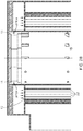
- Figure 1 shows an example embodiment comprising a combustion chamber 10 having burner heads 12 at one end and an exhaust gas outlet 14 at an opposing end. There are fluid deflectors arranged adjacent to the exhaust gas outlet to channel the flow and reduce particulate deposition. There is a fuel and air mix inlet to the burner heads, not shown, and a further secondary combustion air inlet 16 through which secondary combustion air enters the processing apparatus 5. A proportion of this secondary combustion air, in this case 10%, is sent directly across the head to the burners to cool the burner heads. The rest is directed down through heat exchanger 20 flowing through a plurality of tubes 22.
- These plurality of tubes 22 are held within a further outer tube or shell which provides an annular space that is bounded on the outside by an insulating layer 25 and on the inside by an inner tube 27.
- This annular space provides a path for the exhaust gases output via exhaust gas output 14 to travel up through the heat exchanger 20.
- the hot exhaust gases are brought into contact with the cooler secondary combustion air and heat is exchanged between the two. Furthermore, there is a flow communication path between at least some of the tubes 22 and the flow path through which the exhaust gases flow allowing a proportion of the exhaust gases to enter the secondary combustion air causing oxygen depletion of this secondary combustion air.
- the depleted oxygen secondary combustion air then enters the inner tube 27 and rises up around the inner edge of the combustion tube 10. There are inlet apertures 13 providing a flow path from this inner tube 27 into the combustion chamber 10. Thus, the secondary combustion air comprising a portion of exhaust gases enters the combustion chamber through these apertures.
- the size of the apertures and the flow deflector plates 15 associated with them can be selected to control the flow of this secondary combustion air and provide the required degree of mixing while limiting turbulence.
- FIG. 2A shows these flow deflector plates 15 in a little more detail and how in this embodiment they are angled to deflect the input secondary combustion air down away from the burner heads, reducing the amount of exhaust gases that reach the burners and may cause fouling of the burner heads.
- a cooling jacket 30 around the heat exchanger which has an input 35, for receiving a cooling fluid, which in this case is cooling air and an output 40 for outputting a mixture of the cooling air and exhaust gases.
- This cooling air is swirled around the outer surface of the combustion chamber within the cooling jacket 30 reducing the exterior surface temperature of the device giving a safer device and also acting to mix with the hot exhaust gases to provide a looler exhaust. This allows the gases to be safely vented and reduces the cost of materials used in the vents.
- Figure 2B shows an exploded view of the burner head portion of the combustion chamber shown in Figure 2A with the inlets 11 that allow a portion of the secondary combustion air to pass directly over the burner heads to cool them, shown.
- the rest of the combustion air passes though openings 17 into the heat exchanger tubes 22. Typically 10% of the air is used for cooling with the rest being input to the combustion chamber after passing through the heat exchanger.
- Figure 3 shows cross sections through the treatment apparatus along different portions of its length.
- the upper cross section shows the exhaust gas and cooling air output 40, along with outlet apertures 33 for outputting exhaust gas from the heat exchanger into the swirling cooling air within jacket 30.
- These apertures are placed at different circumferential positions on the heat exchanger outer wall and at different heights, although all of them are towards the upper end to allow for a significant heat exchange path prior to output. The distribution of these apertures increases mixing of the exhaust gas and the cooling air.
- the lower cross section shows the cooling air input 35 for inputting the cooling air to the cooling jacket 30. All three show the shell 21 which is bounded by the inner tube 27 and outer insulating layer 25 and in which the heat exchanger tubes 22 are found and which provides the flow path for the exhaust gases.
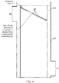
- Figure 4 shows the outer tube 23 of the heat exchanger within the cooling jacket 30.
- outlet apertures 33 which allow the exhaust gas flowing within the outer tube 23 to exit into the cooling jacket 30.
- Providing different circumferential and longitudinal positions for the exhaust gas outlets 33 towards the exhaust gas/cooling air outlet 40 allows for the exhaust gas to remain within the heat exchanger for longer whilst also providing mixing of the exhaust gases with the cooling air.
- the cooling air is swirled around the cooling jacket by fluid deflecting arrangements, not shown, and by the arrangement of the inlet 35 and outlet 40. This increases the mixing of the combustion air and exhaust gases and reduces any localised hotspots.
- the cooling air which enters the outer space 30 around the combustion chamber is tangentially directed such that the gas spins rapidly sweeping the whole of the annular space as it ascends the outside of the combustion chamber.
- exhaust gas holes 33 allow the escape of the hot combustion gas from the heat exchanger assembly into the rapidly spinning cooling air ensuring rapid and complete or near complete mixing of the two gas streams. This arrangement also prevents or at least impedes the cooling air from prematurely entering the combustion chamber through the apertures for outletting the exhaust gas.
- Figure 5 shows a burner head arrangement according to an embodiment in which there are a plurality of burner heads 12 arranged in a circular array. Such an arrangement is an efficient way of providing a burner, however turbulence needs to be limited as it is undesirable that the particulates generated by the burning at one burner head are swept towards another burner head 12 as this may cause fouling of the burner head.
- the combustion chamber is between1 and 1.5m long which may be longer than previous designs. This in conjunction with the preheated combustion gas leads to a significantly longer residence time for the process gases in the hot combustion zone and a higher mean temperature.
- the dimensions of the tubes in the annular space should be designed to take into account the heat flows and pressure drops both forced convective and radiated heat transfer and also to allow for an inevitable fouling of the heat exchanger.
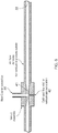
- Figure 6 shows the venturi 41 which is provided within all or a subset of the heat exchanger tubes 22 in some embodiments and which provides a reduced pressure allowing exhaust gases to be sucked into the tube 22 through a calibrated flow inlet 42.
- a calibrated flow inlet 42 of a particular size, a desired amount of exhaust gas can be sucked from the exhaust gas flow and recirculated into the combustion chamber with the secondary combustion air.
- the depletion levels of the oxygen within the combustion air can be controlled.
- a problem with exhaust gases to deplete the oxygen in the combustion air is that particulates are present which can cause fouling.
- a blast cleaner connection 50 can be provided on this venturi 41 which allows air to be periodically blown across the flow inlet and clear any deposited particulates. This method of cleaning the venturi assembly avoids the need for electrically operated cleaning mechanisms in the vicinity of high-temperature acidic gases.
Landscapes
- Engineering & Computer Science (AREA)
- Mechanical Engineering (AREA)
- General Engineering & Computer Science (AREA)
- Environmental & Geological Engineering (AREA)
- Chemical & Material Sciences (AREA)
- Combustion & Propulsion (AREA)
- Incineration Of Waste (AREA)
- Gas Separation By Absorption (AREA)
- Chimneys And Flues (AREA)
Applications Claiming Priority (2)
| Application Number | Priority Date | Filing Date | Title |
|---|---|---|---|
| GB1520427.4A GB2544520A (en) | 2015-11-19 | 2015-11-19 | Effluent gas treatment apparatus and method |
| PCT/GB2016/053338 WO2017085453A1 (en) | 2015-11-19 | 2016-10-27 | Effluent gas treatment apparatus and method |
Publications (2)
| Publication Number | Publication Date |
|---|---|
| EP3377816A1 EP3377816A1 (en) | 2018-09-26 |
| EP3377816B1 true EP3377816B1 (en) | 2020-04-22 |
Family
ID=55133048
Family Applications (1)
| Application Number | Title | Priority Date | Filing Date |
|---|---|---|---|
| EP16788759.5A Active EP3377816B1 (en) | 2015-11-19 | 2016-10-27 | Effluent gas treatment apparatus |
Country Status (8)
| Country | Link |
|---|---|
| US (1) | US10767860B2 (enExample) |
| EP (1) | EP3377816B1 (enExample) |
| JP (1) | JP6987055B2 (enExample) |
| KR (1) | KR102563674B1 (enExample) |
| CN (1) | CN108291716B (enExample) |
| GB (1) | GB2544520A (enExample) |
| SG (1) | SG11201804229QA (enExample) |
| WO (1) | WO2017085453A1 (enExample) |
Families Citing this family (5)
| Publication number | Priority date | Publication date | Assignee | Title |
|---|---|---|---|---|
| CN108716683B (zh) * | 2018-06-25 | 2019-08-20 | 河南孚点电子科技有限公司 | 一种用于处理沼气的安全燃烧装置 |
| WO2021101444A2 (zh) | 2019-11-21 | 2021-05-27 | 益科斯有限公司 | 一种处理气体污染物的装置 |
| GB2608816A (en) * | 2021-07-13 | 2023-01-18 | Edwards Ltd | Abatement apparatus |
| CN117072988B (zh) * | 2023-08-22 | 2025-10-10 | 浙江美宝工业科技股份有限公司 | 一种节能环保型硫磺尾气焚烧炉 |
| CN118347003B (zh) * | 2024-06-17 | 2024-11-26 | 江苏中圣高科技产业有限公司 | 一种适用多种工况废气废液混烧的低氮燃烧器及其燃烧方法 |
Family Cites Families (31)
| Publication number | Priority date | Publication date | Assignee | Title |
|---|---|---|---|---|
| US2470860A (en) * | 1949-05-24 | Heater | ||
| US3220460A (en) * | 1963-04-12 | 1965-11-30 | Colt Ventilation & Heating Ltd | Heat generators |
| US3549333A (en) * | 1968-07-23 | 1970-12-22 | Universal Oil Prod Co | Recuperative form of direct thermal incinerator |
| US3604824A (en) * | 1970-04-27 | 1971-09-14 | Universal Oil Prod Co | Thermal incineration unit |
| US3806322A (en) * | 1972-06-29 | 1974-04-23 | Universal Oil Prod Co | Recuperative form of catalytic-thermal incinerator |
| CA1070668A (en) * | 1975-10-08 | 1980-01-29 | Steel Company Of Canada | Tubeless heat recuperator |
| JPS52160273U (enExample) * | 1976-05-29 | 1977-12-05 | ||
| JPS55143306A (en) * | 1979-04-21 | 1980-11-08 | Daido Steel Co Ltd | Low noise recuperator of exhaust combustion-gas drawing type |
| JPS5618292A (en) * | 1979-07-21 | 1981-02-20 | Daido Steel Co Ltd | Recuperator with low noise and nox |
| DE3107664C2 (de) * | 1981-02-28 | 1986-11-06 | Kraftanlagen Ag, 6900 Heidelberg | Einrichtung zur Nachverbrennung organischer Bestandteile in Proßesabgasen |
| US4445842A (en) * | 1981-11-05 | 1984-05-01 | Thermal Systems Engineering, Inc. | Recuperative burner with exhaust gas recirculation means |
| ATE89907T1 (de) * | 1990-03-10 | 1993-06-15 | Krantz H Gmbh & Co | Vorrichtung zum verbrennen von in einem abluftstrom enthaltenen oxidierbaren bestandteilen. |
| FR2688577A1 (fr) * | 1992-03-10 | 1993-09-17 | Dumoutier Massetat Sa | Dispositif d'epuration des effluents gazeux. |
| US5384051A (en) * | 1993-02-05 | 1995-01-24 | Mcginness; Thomas G. | Supercritical oxidation reactor |
| JPH07233913A (ja) * | 1994-02-24 | 1995-09-05 | Sanyo Electric Co Ltd | 燃焼装置 |
| US5427746A (en) * | 1994-03-08 | 1995-06-27 | W. R. Grace & Co.-Conn. | Flow modification devices for reducing emissions from thermal voc oxidizers |
| JPH11132404A (ja) | 1997-10-31 | 1999-05-21 | Miura Co Ltd | 水管ボイラ |
| US6742335B2 (en) * | 2002-07-11 | 2004-06-01 | Clean Air Power, Inc. | EGR control system and method for an internal combustion engine |
| US7004749B2 (en) * | 2002-08-29 | 2006-02-28 | Noritz Corporation | Combustion apparatus |
| US6964158B2 (en) * | 2003-02-10 | 2005-11-15 | Southwest Research Institute | Method and apparatus for particle-free exhaust gas recirculation for internal combustion engines |
| JP2005226847A (ja) * | 2004-02-10 | 2005-08-25 | Ebara Corp | 燃焼装置及び燃焼方法 |
| WO2006101987A2 (en) * | 2005-03-17 | 2006-09-28 | Southwest Research Institute | Use of recirculated exhaust gas in a burner-based exhaust generation system for reduced fuel consumption and for cooling |
| US8272431B2 (en) * | 2005-12-27 | 2012-09-25 | Caterpillar Inc. | Heat exchanger using graphite foam |
| JP2007198682A (ja) * | 2006-01-27 | 2007-08-09 | Takuma Co Ltd | 蓄熱脱臭システム |
| CN102116481A (zh) * | 2009-12-30 | 2011-07-06 | 中冶长天国际工程有限责任公司 | 一种再燃烧设备及其余热回收方法 |
| DE102010012005A1 (de) * | 2010-03-15 | 2011-09-15 | Dürr Systems GmbH | Thermische Abluftreinigungsanlage |
| EP2884174B1 (en) * | 2012-08-07 | 2018-03-21 | Hino Motors, Ltd. | Burner |
| US20140090804A1 (en) * | 2012-10-03 | 2014-04-03 | Delio SAMZ | Heat Exchanger |
| EP2957835B1 (en) * | 2014-06-18 | 2018-03-21 | Ansaldo Energia Switzerland AG | Method for recirculation of exhaust gas from a combustion chamber of a combustor of a gas turbine and gas turbine for conducting said method |
| DE102014018178A1 (de) * | 2014-12-09 | 2016-06-09 | Eisenmann Se | Thermische Nachverbrennungsanlage |
| CN104501203A (zh) * | 2014-12-19 | 2015-04-08 | 深圳市山水乐环保科技有限公司 | 缺氧富二氧化碳气体实现低氮燃烧的气体混合比例控制的设备及方法 |
-
2015
- 2015-11-19 GB GB1520427.4A patent/GB2544520A/en not_active Withdrawn
-
2016
- 2016-10-27 EP EP16788759.5A patent/EP3377816B1/en active Active
- 2016-10-27 KR KR1020187013880A patent/KR102563674B1/ko active Active
- 2016-10-27 CN CN201680067725.XA patent/CN108291716B/zh active Active
- 2016-10-27 US US15/777,023 patent/US10767860B2/en active Active
- 2016-10-27 JP JP2018525584A patent/JP6987055B2/ja active Active
- 2016-10-27 WO PCT/GB2016/053338 patent/WO2017085453A1/en not_active Ceased
- 2016-10-27 SG SG11201804229QA patent/SG11201804229QA/en unknown
Non-Patent Citations (1)
| Title |
|---|
| None * |
Also Published As
| Publication number | Publication date |
|---|---|
| KR20180083334A (ko) | 2018-07-20 |
| JP2018534522A (ja) | 2018-11-22 |
| JP6987055B2 (ja) | 2021-12-22 |
| SG11201804229QA (en) | 2018-06-28 |
| GB201520427D0 (en) | 2016-01-06 |
| CN108291716B (zh) | 2019-11-22 |
| WO2017085453A1 (en) | 2017-05-26 |
| EP3377816A1 (en) | 2018-09-26 |
| US20180335210A1 (en) | 2018-11-22 |
| CN108291716A (zh) | 2018-07-17 |
| US10767860B2 (en) | 2020-09-08 |
| KR102563674B1 (ko) | 2023-08-03 |
| GB2544520A (en) | 2017-05-24 |
Similar Documents
| Publication | Publication Date | Title |
|---|---|---|
| EP3377816B1 (en) | Effluent gas treatment apparatus | |
| US11242790B2 (en) | Flow reversing mixer assembly | |
| CN100587033C (zh) | 加热更均匀的裂解炉 | |
| US4304549A (en) | Recuperator burner for industrial furnaces | |
| US20040201142A1 (en) | Injection lance for uniformly injecting a steam/ammonia mixture into a fossil fuel combustion stream | |
| KR100563761B1 (ko) | 짝을 이룬 버너로 구획된 연소 시스템을 갖는 열분해 가열기 | |
| HU218077B (hu) | Berendezés és eljárás oxidálható részek elégetésére tisztítandó hordozógázban | |
| EP4127562B1 (en) | Flameless combustion burner for an endothermic reaction process | |
| US11815264B2 (en) | Burner | |
| JP3239181U (ja) | バーナー | |
| KR100906702B1 (ko) | 산업용 노에서의 버너에 의한 연소 방법 및 이를 위한 버너 | |
| JP4309771B2 (ja) | 多管式貫流ボイラ | |
| CN103307611B (zh) | 用于通过燃烧去除有害气体的装置 | |
| US6780004B2 (en) | Thermal post-combustion device | |
| EP4150254B1 (en) | Plugging resistant free-jet burner and method | |
| ITRM960018A1 (it) | Reattore catalitico isotermo per reazioni endotermiche ad alta tempe ratura | |
| CN212081232U (zh) | 一种尾气喷管组件及低氮燃烧器 | |
| CN117716175A (zh) | 入口头部组件 | |
| CN217503693U (zh) | 一种VOCs废气处理设备 | |
| CN111981502A (zh) | 一种配合辐射管烧嘴使用的高效预热器 | |
| US20090252664A1 (en) | Methods and apparatus for heating reagents and effluents in abatement systems | |
| CA2345772A1 (en) | Low nox burner | |
| US20050152822A1 (en) | NOx removal system for boilers | |
| JP2004053219A (ja) | 燃焼除害装置 | |
| KR102632470B1 (ko) | 질소 산화물 저감형 버너 |
Legal Events
| Date | Code | Title | Description |
|---|---|---|---|
| STAA | Information on the status of an ep patent application or granted ep patent |
Free format text: STATUS: UNKNOWN |
|
| STAA | Information on the status of an ep patent application or granted ep patent |
Free format text: STATUS: THE INTERNATIONAL PUBLICATION HAS BEEN MADE |
|
| PUAI | Public reference made under article 153(3) epc to a published international application that has entered the european phase |
Free format text: ORIGINAL CODE: 0009012 |
|
| STAA | Information on the status of an ep patent application or granted ep patent |
Free format text: STATUS: REQUEST FOR EXAMINATION WAS MADE |
|
| 17P | Request for examination filed |
Effective date: 20180510 |
|
| AK | Designated contracting states |
Kind code of ref document: A1 Designated state(s): AL AT BE BG CH CY CZ DE DK EE ES FI FR GB GR HR HU IE IS IT LI LT LU LV MC MK MT NL NO PL PT RO RS SE SI SK SM TR |
|
| AX | Request for extension of the european patent |
Extension state: BA ME |
|
| DAV | Request for validation of the european patent (deleted) | ||
| DAX | Request for extension of the european patent (deleted) | ||
| STAA | Information on the status of an ep patent application or granted ep patent |
Free format text: STATUS: EXAMINATION IS IN PROGRESS |
|
| 17Q | First examination report despatched |
Effective date: 20190403 |
|
| GRAP | Despatch of communication of intention to grant a patent |
Free format text: ORIGINAL CODE: EPIDOSNIGR1 |
|
| STAA | Information on the status of an ep patent application or granted ep patent |
Free format text: STATUS: GRANT OF PATENT IS INTENDED |
|
| INTG | Intention to grant announced |
Effective date: 20191209 |
|
| GRAS | Grant fee paid |
Free format text: ORIGINAL CODE: EPIDOSNIGR3 |
|
| GRAA | (expected) grant |
Free format text: ORIGINAL CODE: 0009210 |
|
| STAA | Information on the status of an ep patent application or granted ep patent |
Free format text: STATUS: THE PATENT HAS BEEN GRANTED |
|
| AK | Designated contracting states |
Kind code of ref document: B1 Designated state(s): AL AT BE BG CH CY CZ DE DK EE ES FI FR GB GR HR HU IE IS IT LI LT LU LV MC MK MT NL NO PL PT RO RS SE SI SK SM TR |
|
| REG | Reference to a national code |
Ref country code: CH Ref legal event code: EP |
|
| REG | Reference to a national code |
Ref country code: IE Ref legal event code: FG4D |
|
| REG | Reference to a national code |
Ref country code: DE Ref legal event code: R096 Ref document number: 602016034664 Country of ref document: DE |
|
| REG | Reference to a national code |
Ref country code: AT Ref legal event code: REF Ref document number: 1260606 Country of ref document: AT Kind code of ref document: T Effective date: 20200515 |
|
| REG | Reference to a national code |
Ref country code: LT Ref legal event code: MG4D |
|
| REG | Reference to a national code |
Ref country code: NL Ref legal event code: MP Effective date: 20200422 |
|
| PG25 | Lapsed in a contracting state [announced via postgrant information from national office to epo] |
Ref country code: FI Free format text: LAPSE BECAUSE OF FAILURE TO SUBMIT A TRANSLATION OF THE DESCRIPTION OR TO PAY THE FEE WITHIN THE PRESCRIBED TIME-LIMIT Effective date: 20200422 Ref country code: GR Free format text: LAPSE BECAUSE OF FAILURE TO SUBMIT A TRANSLATION OF THE DESCRIPTION OR TO PAY THE FEE WITHIN THE PRESCRIBED TIME-LIMIT Effective date: 20200723 Ref country code: PT Free format text: LAPSE BECAUSE OF FAILURE TO SUBMIT A TRANSLATION OF THE DESCRIPTION OR TO PAY THE FEE WITHIN THE PRESCRIBED TIME-LIMIT Effective date: 20200824 Ref country code: IS Free format text: LAPSE BECAUSE OF FAILURE TO SUBMIT A TRANSLATION OF THE DESCRIPTION OR TO PAY THE FEE WITHIN THE PRESCRIBED TIME-LIMIT Effective date: 20200822 Ref country code: NO Free format text: LAPSE BECAUSE OF FAILURE TO SUBMIT A TRANSLATION OF THE DESCRIPTION OR TO PAY THE FEE WITHIN THE PRESCRIBED TIME-LIMIT Effective date: 20200722 Ref country code: SE Free format text: LAPSE BECAUSE OF FAILURE TO SUBMIT A TRANSLATION OF THE DESCRIPTION OR TO PAY THE FEE WITHIN THE PRESCRIBED TIME-LIMIT Effective date: 20200422 Ref country code: NL Free format text: LAPSE BECAUSE OF FAILURE TO SUBMIT A TRANSLATION OF THE DESCRIPTION OR TO PAY THE FEE WITHIN THE PRESCRIBED TIME-LIMIT Effective date: 20200422 Ref country code: LT Free format text: LAPSE BECAUSE OF FAILURE TO SUBMIT A TRANSLATION OF THE DESCRIPTION OR TO PAY THE FEE WITHIN THE PRESCRIBED TIME-LIMIT Effective date: 20200422 |
|
| REG | Reference to a national code |
Ref country code: AT Ref legal event code: MK05 Ref document number: 1260606 Country of ref document: AT Kind code of ref document: T Effective date: 20200422 |
|
| PG25 | Lapsed in a contracting state [announced via postgrant information from national office to epo] |
Ref country code: RS Free format text: LAPSE BECAUSE OF FAILURE TO SUBMIT A TRANSLATION OF THE DESCRIPTION OR TO PAY THE FEE WITHIN THE PRESCRIBED TIME-LIMIT Effective date: 20200422 Ref country code: BG Free format text: LAPSE BECAUSE OF FAILURE TO SUBMIT A TRANSLATION OF THE DESCRIPTION OR TO PAY THE FEE WITHIN THE PRESCRIBED TIME-LIMIT Effective date: 20200722 Ref country code: LV Free format text: LAPSE BECAUSE OF FAILURE TO SUBMIT A TRANSLATION OF THE DESCRIPTION OR TO PAY THE FEE WITHIN THE PRESCRIBED TIME-LIMIT Effective date: 20200422 Ref country code: HR Free format text: LAPSE BECAUSE OF FAILURE TO SUBMIT A TRANSLATION OF THE DESCRIPTION OR TO PAY THE FEE WITHIN THE PRESCRIBED TIME-LIMIT Effective date: 20200422 |
|
| PG25 | Lapsed in a contracting state [announced via postgrant information from national office to epo] |
Ref country code: AL Free format text: LAPSE BECAUSE OF FAILURE TO SUBMIT A TRANSLATION OF THE DESCRIPTION OR TO PAY THE FEE WITHIN THE PRESCRIBED TIME-LIMIT Effective date: 20200422 |
|
| REG | Reference to a national code |
Ref country code: DE Ref legal event code: R097 Ref document number: 602016034664 Country of ref document: DE |
|
| PG25 | Lapsed in a contracting state [announced via postgrant information from national office to epo] |
Ref country code: ES Free format text: LAPSE BECAUSE OF FAILURE TO SUBMIT A TRANSLATION OF THE DESCRIPTION OR TO PAY THE FEE WITHIN THE PRESCRIBED TIME-LIMIT Effective date: 20200422 Ref country code: DK Free format text: LAPSE BECAUSE OF FAILURE TO SUBMIT A TRANSLATION OF THE DESCRIPTION OR TO PAY THE FEE WITHIN THE PRESCRIBED TIME-LIMIT Effective date: 20200422 Ref country code: SM Free format text: LAPSE BECAUSE OF FAILURE TO SUBMIT A TRANSLATION OF THE DESCRIPTION OR TO PAY THE FEE WITHIN THE PRESCRIBED TIME-LIMIT Effective date: 20200422 Ref country code: AT Free format text: LAPSE BECAUSE OF FAILURE TO SUBMIT A TRANSLATION OF THE DESCRIPTION OR TO PAY THE FEE WITHIN THE PRESCRIBED TIME-LIMIT Effective date: 20200422 Ref country code: EE Free format text: LAPSE BECAUSE OF FAILURE TO SUBMIT A TRANSLATION OF THE DESCRIPTION OR TO PAY THE FEE WITHIN THE PRESCRIBED TIME-LIMIT Effective date: 20200422 Ref country code: IT Free format text: LAPSE BECAUSE OF FAILURE TO SUBMIT A TRANSLATION OF THE DESCRIPTION OR TO PAY THE FEE WITHIN THE PRESCRIBED TIME-LIMIT Effective date: 20200422 Ref country code: RO Free format text: LAPSE BECAUSE OF FAILURE TO SUBMIT A TRANSLATION OF THE DESCRIPTION OR TO PAY THE FEE WITHIN THE PRESCRIBED TIME-LIMIT Effective date: 20200422 Ref country code: CZ Free format text: LAPSE BECAUSE OF FAILURE TO SUBMIT A TRANSLATION OF THE DESCRIPTION OR TO PAY THE FEE WITHIN THE PRESCRIBED TIME-LIMIT Effective date: 20200422 |
|
| PG25 | Lapsed in a contracting state [announced via postgrant information from national office to epo] |
Ref country code: PL Free format text: LAPSE BECAUSE OF FAILURE TO SUBMIT A TRANSLATION OF THE DESCRIPTION OR TO PAY THE FEE WITHIN THE PRESCRIBED TIME-LIMIT Effective date: 20200422 Ref country code: SK Free format text: LAPSE BECAUSE OF FAILURE TO SUBMIT A TRANSLATION OF THE DESCRIPTION OR TO PAY THE FEE WITHIN THE PRESCRIBED TIME-LIMIT Effective date: 20200422 |
|
| PLBE | No opposition filed within time limit |
Free format text: ORIGINAL CODE: 0009261 |
|
| STAA | Information on the status of an ep patent application or granted ep patent |
Free format text: STATUS: NO OPPOSITION FILED WITHIN TIME LIMIT |
|
| 26N | No opposition filed |
Effective date: 20210125 |
|
| PG25 | Lapsed in a contracting state [announced via postgrant information from national office to epo] |
Ref country code: SI Free format text: LAPSE BECAUSE OF FAILURE TO SUBMIT A TRANSLATION OF THE DESCRIPTION OR TO PAY THE FEE WITHIN THE PRESCRIBED TIME-LIMIT Effective date: 20200422 |
|
| REG | Reference to a national code |
Ref country code: CH Ref legal event code: PL |
|
| GBPC | Gb: european patent ceased through non-payment of renewal fee |
Effective date: 20201027 |
|
| PG25 | Lapsed in a contracting state [announced via postgrant information from national office to epo] |
Ref country code: LU Free format text: LAPSE BECAUSE OF NON-PAYMENT OF DUE FEES Effective date: 20201027 Ref country code: MC Free format text: LAPSE BECAUSE OF FAILURE TO SUBMIT A TRANSLATION OF THE DESCRIPTION OR TO PAY THE FEE WITHIN THE PRESCRIBED TIME-LIMIT Effective date: 20200422 |
|
| REG | Reference to a national code |
Ref country code: BE Ref legal event code: MM Effective date: 20201031 |
|
| PG25 | Lapsed in a contracting state [announced via postgrant information from national office to epo] |
Ref country code: GB Free format text: LAPSE BECAUSE OF NON-PAYMENT OF DUE FEES Effective date: 20201027 Ref country code: LI Free format text: LAPSE BECAUSE OF NON-PAYMENT OF DUE FEES Effective date: 20201031 Ref country code: BE Free format text: LAPSE BECAUSE OF NON-PAYMENT OF DUE FEES Effective date: 20201031 Ref country code: CH Free format text: LAPSE BECAUSE OF NON-PAYMENT OF DUE FEES Effective date: 20201031 |
|
| PG25 | Lapsed in a contracting state [announced via postgrant information from national office to epo] |
Ref country code: IE Free format text: LAPSE BECAUSE OF NON-PAYMENT OF DUE FEES Effective date: 20201027 |
|
| PG25 | Lapsed in a contracting state [announced via postgrant information from national office to epo] |
Ref country code: TR Free format text: LAPSE BECAUSE OF FAILURE TO SUBMIT A TRANSLATION OF THE DESCRIPTION OR TO PAY THE FEE WITHIN THE PRESCRIBED TIME-LIMIT Effective date: 20200422 Ref country code: MT Free format text: LAPSE BECAUSE OF FAILURE TO SUBMIT A TRANSLATION OF THE DESCRIPTION OR TO PAY THE FEE WITHIN THE PRESCRIBED TIME-LIMIT Effective date: 20200422 Ref country code: CY Free format text: LAPSE BECAUSE OF FAILURE TO SUBMIT A TRANSLATION OF THE DESCRIPTION OR TO PAY THE FEE WITHIN THE PRESCRIBED TIME-LIMIT Effective date: 20200422 |
|
| PG25 | Lapsed in a contracting state [announced via postgrant information from national office to epo] |
Ref country code: MK Free format text: LAPSE BECAUSE OF FAILURE TO SUBMIT A TRANSLATION OF THE DESCRIPTION OR TO PAY THE FEE WITHIN THE PRESCRIBED TIME-LIMIT Effective date: 20200422 |
|
| REG | Reference to a national code |
Ref country code: DE Ref legal event code: R082 Ref document number: 602016034664 Country of ref document: DE Representative=s name: FLEUCHAUS & GALLO PARTNERSCHAFT MBB - PATENT- , DE Ref country code: DE Ref legal event code: R082 Ref document number: 602016034664 Country of ref document: DE Representative=s name: FLEUCHAUS & GALLO PARTNERSCHAFT MBB PATENTANWA, DE |
|
| P01 | Opt-out of the competence of the unified patent court (upc) registered |
Effective date: 20230504 |
|
| PGFP | Annual fee paid to national office [announced via postgrant information from national office to epo] |
Ref country code: DE Payment date: 20251029 Year of fee payment: 10 |
|
| PGFP | Annual fee paid to national office [announced via postgrant information from national office to epo] |
Ref country code: FR Payment date: 20251027 Year of fee payment: 10 |