EP3377348B1 - Dispositif de poussée et/ou de traction pour capote de véhicule et capote pour toit ouvrant de véhicule - Google Patents
Dispositif de poussée et/ou de traction pour capote de véhicule et capote pour toit ouvrant de véhicule Download PDFInfo
- Publication number
- EP3377348B1 EP3377348B1 EP16788026.9A EP16788026A EP3377348B1 EP 3377348 B1 EP3377348 B1 EP 3377348B1 EP 16788026 A EP16788026 A EP 16788026A EP 3377348 B1 EP3377348 B1 EP 3377348B1
- Authority
- EP
- European Patent Office
- Prior art keywords
- link
- pushing
- pulling device
- guide
- section
- Prior art date
- Legal status (The legal status is an assumption and is not a legal conclusion. Google has not performed a legal analysis and makes no representation as to the accuracy of the status listed.)
- Active
Links
Images
Classifications
-
- B—PERFORMING OPERATIONS; TRANSPORTING
- B60—VEHICLES IN GENERAL
- B60J—WINDOWS, WINDSCREENS, NON-FIXED ROOFS, DOORS, OR SIMILAR DEVICES FOR VEHICLES; REMOVABLE EXTERNAL PROTECTIVE COVERINGS SPECIALLY ADAPTED FOR VEHICLES
- B60J7/00—Non-fixed roofs; Roofs with movable panels, e.g. rotary sunroofs
- B60J7/08—Non-fixed roofs; Roofs with movable panels, e.g. rotary sunroofs of non-sliding type, i.e. movable or removable roofs or panels, e.g. let-down tops or roofs capable of being easily detached or of assuming a collapsed or inoperative position
- B60J7/12—Non-fixed roofs; Roofs with movable panels, e.g. rotary sunroofs of non-sliding type, i.e. movable or removable roofs or panels, e.g. let-down tops or roofs capable of being easily detached or of assuming a collapsed or inoperative position foldable; Tensioning mechanisms therefor, e.g. struts
- B60J7/14—Non-fixed roofs; Roofs with movable panels, e.g. rotary sunroofs of non-sliding type, i.e. movable or removable roofs or panels, e.g. let-down tops or roofs capable of being easily detached or of assuming a collapsed or inoperative position foldable; Tensioning mechanisms therefor, e.g. struts with a plurality of rigid plate-like elements or rigid non plate-like elements, e.g. with non-slidable, but pivotable or foldable movement
- B60J7/143—Non-fixed roofs; Roofs with movable panels, e.g. rotary sunroofs of non-sliding type, i.e. movable or removable roofs or panels, e.g. let-down tops or roofs capable of being easily detached or of assuming a collapsed or inoperative position foldable; Tensioning mechanisms therefor, e.g. struts with a plurality of rigid plate-like elements or rigid non plate-like elements, e.g. with non-slidable, but pivotable or foldable movement for covering the passenger compartment
-
- B—PERFORMING OPERATIONS; TRANSPORTING
- B60—VEHICLES IN GENERAL
- B60J—WINDOWS, WINDSCREENS, NON-FIXED ROOFS, DOORS, OR SIMILAR DEVICES FOR VEHICLES; REMOVABLE EXTERNAL PROTECTIVE COVERINGS SPECIALLY ADAPTED FOR VEHICLES
- B60J7/00—Non-fixed roofs; Roofs with movable panels, e.g. rotary sunroofs
- B60J7/08—Non-fixed roofs; Roofs with movable panels, e.g. rotary sunroofs of non-sliding type, i.e. movable or removable roofs or panels, e.g. let-down tops or roofs capable of being easily detached or of assuming a collapsed or inoperative position
- B60J7/12—Non-fixed roofs; Roofs with movable panels, e.g. rotary sunroofs of non-sliding type, i.e. movable or removable roofs or panels, e.g. let-down tops or roofs capable of being easily detached or of assuming a collapsed or inoperative position foldable; Tensioning mechanisms therefor, e.g. struts
- B60J7/1226—Soft tops for convertible vehicles
- B60J7/1234—Soft tops for convertible vehicles characterised by arches, e.g. shape or material
- B60J7/1252—Soft tops for convertible vehicles characterised by arches, e.g. shape or material characterised by lateral arches
-
- B—PERFORMING OPERATIONS; TRANSPORTING
- B60—VEHICLES IN GENERAL
- B60J—WINDOWS, WINDSCREENS, NON-FIXED ROOFS, DOORS, OR SIMILAR DEVICES FOR VEHICLES; REMOVABLE EXTERNAL PROTECTIVE COVERINGS SPECIALLY ADAPTED FOR VEHICLES
- B60J7/00—Non-fixed roofs; Roofs with movable panels, e.g. rotary sunroofs
- B60J7/02—Non-fixed roofs; Roofs with movable panels, e.g. rotary sunroofs of sliding type, e.g. comprising guide shoes
- B60J7/026—Non-fixed roofs; Roofs with movable panels, e.g. rotary sunroofs of sliding type, e.g. comprising guide shoes with rigid non plate-like elements, e.g. for convertible vehicles
-
- B—PERFORMING OPERATIONS; TRANSPORTING
- B60—VEHICLES IN GENERAL
- B60J—WINDOWS, WINDSCREENS, NON-FIXED ROOFS, DOORS, OR SIMILAR DEVICES FOR VEHICLES; REMOVABLE EXTERNAL PROTECTIVE COVERINGS SPECIALLY ADAPTED FOR VEHICLES
- B60J7/00—Non-fixed roofs; Roofs with movable panels, e.g. rotary sunroofs
- B60J7/02—Non-fixed roofs; Roofs with movable panels, e.g. rotary sunroofs of sliding type, e.g. comprising guide shoes
- B60J7/04—Non-fixed roofs; Roofs with movable panels, e.g. rotary sunroofs of sliding type, e.g. comprising guide shoes with rigid plate-like element or elements, e.g. open roofs with harmonica-type folding rigid panels
- B60J7/057—Driving or actuating arrangements e.g. manually operated levers or knobs
- B60J7/0573—Driving or actuating arrangements e.g. manually operated levers or knobs power driven arrangements, e.g. electrical
Definitions
- the invention relates to a pushing and / or pulling device for a vehicle top according to the preamble of claim 1 and a corresponding top for an openable vehicle roof with such a pushing and / or pulling device.
- tops for openable vehicle roofs usually have at least two roof sections, a front first roof section being connectable to a windshield cross member and a rear second roof section having a flat rear window. These tops are usually moved over a pivot point, the top being moved high above the vehicle. This requires enormous effort and thus also robust and heavy drive mechanisms and drives.
- the folding top is ensured, for example, by scissor-type joints.
- a convertible top section can be guided between the longitudinal members of the vehicle roof. This means that at least one convertible top section is designed to be displaceable.
- a convertible top for a motorized puristic small passenger vehicle which is designed in particular as a so-called roadster or speedster.
- a convertible top middle part is pivotably mounted on a rear part between a position lowered between seat positions and a raised position supported on an upper edge of a windshield.
- Two collapsible covers guided by the middle part of the top are made from one side on both sides in the raised position of the top part hidden position behind the sitting positions can be pushed forward over the sitting positions.
- a vehicle with a top for an openable roof is known.
- the vehicle has two removable side roof frames with C-pillars attached to the rear.
- a sliding roof element in particular a folding sliding roof or a louvre roof, is accommodated in the guides of the side roof frame.
- a flat rear roof element in particular a rear window, is pivotally mounted on the body. The displaceable roof element is received in a fully open rear end position in a receiving area assigned to the flat roof element.
- a convertible vehicle is known with an openable roof, at least in some areas provided with a flexible cover, which in its front roof area comprises a rigid end area overlapped by the cover.
- the front roof area can be stored in a body recess in the same orientation as when the roof is closed, that is to say that the surface of the front roof area which points outwards when the roof is closed also points upwards when the roof is open.
- the roof can be placed in a so-called Z-fold, the cover being Z-shaped with an upper section above the roof top and a lower section around the rear window and an intermediate section connecting them diagonally.
- the front roof area further comprises a longitudinally displaceable additional support, which is arranged below the cover and can be moved relative to it by means of a push-pull linkage.
- a Support body comprises, which can be assigned a fixed structure, and which has a device for summarizing a connected blind, which receives at its free end a rod which is supported by rod-shaped means.
- the rod-shaped means are flexible when they are guided and essentially rigid when they are loose.
- the rod-shaped means interact with drive means which are provided in the support body and are actuated by a motor.
- the rod-shaped means are formed by means of plates which are essentially polygonal, preferably rectangular, and which form one or more slots for the passage of one or two flexible laminates.
- the plates have centering pins on one side and centering seats on the other side to provide mutual coupling when the plates are next to each other.
- a recess is provided which is shaped like a peripheral section, while a bevel is defined on the opposite edge.
- the plates are arranged adjacent to one another such that the recess is provided alternately on one edge and on the opposite edge, so that a plurality of recesses are provided on the two opposite edges of the two, which in practice have a plurality of seats for the rod-like Define means.
- an actuator which comprises a series of elements, each pivotable to the next, and a housing in which at least a part of the series of elements is accommodated, one end of the series freely projecting over an outlet of the housing.
- the elements are guided to follow a curved path to the housing exit and are driven along the path by a drive mechanism to vary the total length of the elements projecting beyond the exit.
- the protruding elements are separated by an essentially rigid, self-supporting column Timing belt held in a linear orientation that gradually engages the elements as they exit the housing exit.
- a generic convertible top for an openable vehicle roof which has at least two convertible top sections.
- a front first convertible top section can be coupled to a windshield cross member and at least one convertible top section is designed to be displaceable and a rear second convertible top section can be pivoted and / or lowered.
- a third convertible top section is flexible and is arranged between the first convertible top section and second convertible section and is driven by a generic self-supporting pushing and / or pulling device, the third convertible section being able to be folded over the rear second convertible section during an opening process such that an outer side after the folding process of the third convertible top section faces an outside of the second convertible top section.
- the front first convertible top section is coupled to the pushing and / or pulling device which moves the first convertible top section essentially along the longitudinal direction of the vehicle.
- the pushing and / or pulling device is connected to an end region of the first convertible top section facing a vehicle font and tows the first convertible top section with the third convertible top section when the convertible top is opened towards the rear of the vehicle and when the convertible top is closed towards the front of the vehicle.
- the pushing and / or pulling device comprises, for example, two chains with several pushing and / or pulling elements, which are guided in a guide arranged in the region of the second convertible top section. The two chains run along the side edges of the convertible top.
- Two adjacent pushing and / or pulling elements are connected to one another via a swivel joint, the axes of rotation of the pushing and / or pulling elements running parallel to the roof plane. Also are two adjacent push and / or pull elements can be locked against each other by locking means.
- the object of the invention is to provide a pushing and / or pulling device for a vehicle top and a top for an openable vehicle roof with such a pushing and / or pulling device, which several top sections of the openable vehicle roof with little effort between a closed position of use and can move an invisible non-use position and occupies less storage space than conventional push and / or pull structures in the non-use position.
- the object is achieved by providing a pushing and / or pulling device for a vehicle top with the features of claim 1 and a top for an openable vehicle roof with the features of claim 13.
- two link chains are provided, each having a plurality of link elements and running at a predetermined distance from each other.
- the link chains are each guided at one end in a guide, which predetermine a direction of movement and the distance of the link chains from one another, and connected to one another at the other end via a cross connection, so that the link chains run in a common plane when leaving the guide.
- two adjacent link elements of the link chains are each movably connected to one another by means of a joint, so that at least some of the link elements are placed in a corresponding storage when the link chains are moved into the respective guide, the adjacent link elements abutting each other when leaving the respective guide and support each other.
- pivot axes between two adjacent link elements of the respective link chain have a predetermined angle of inclination to the common plane, the pivot axes of the two link chains being inclined relative to one another, so that the link chains run cantilevered in the predetermined direction of movement and block each other against other directions of movement.
- the described alignment of the pivot axes of the adjacent link elements enables a self-supporting pushing and / or pulling device with two link chains which can be easily rolled up in the relaxed or flexible state and / or stowed in a storage compartment.
- the cantilever effect is due to the distance specified via the cross connection at one end of the link chains or the distance between the link chains when leaving the respective guide, which causes the link chains to be mutually supported, and the adjacent link elements which support one another after leaving the guide of the respective link chain.
- the adjacent link elements of the respective link chains are connected to one another in such a way that they can only be pivoted relative to one another about a predetermined pivot axis.
- the adjacent link elements of a second link chain can likewise only pivot about a second pivot axis, so that the second link chain can also only bend about these second pivot axes between adjacent link elements.
- the adjacent link elements of the link chains stiffen against each other when a force acts in the opposite direction of the respective pivot axis, since the adjacent link elements touch and thus prevent angling.
- the first link chain blocks angling of the second link chain about the second pivot axes by the predetermined distance
- the second link chain blocks angling of the first link chain about the first pivot axes due to the predetermined distance.
- the two link chains or their pivot axes are tilted in opposite directions and connected to one another at the free end via the cross connection at a predetermined distance and leave the guide at a predetermined distance from one another.
- the two link chains stiffen in cross section to form a "V” or an inverted “V” or a U. It is thus possible to push an element arranged on the connected ends of the link chains in a cantilever manner out of the guide without the latter leaving the predetermined direction can.
- the joint between two adjacent link elements can be represented, for example, as a hinge which can "only" move like a swivel wing.
- the joint allows the adjacent link elements to be rotated in the stored state and is designed, for example, as a ball joint.
- the contacting surfaces of the adjacent link elements shaped so that they lead to each other when touched.
- This can be represented, for example, by a “tongue and groove system” which has corresponding cutouts and protrusions. Due to the movable connection between two adjacent link elements, the freedom of movement of the two link chains can advantageously be increased and the link chains can be stored in the storage space-saving.
- a convertible top for an openable vehicle roof which has a plurality of convertible top sections and a pushing and / or pulling device according to the invention, which moves the convertible top sections from a position of use to a position of non-use.
- the angles of inclination of the pivot axes to the common plane can each be specified in a value range greater than 0 ° and less than 180 °.
- the angles of inclination are preferably selected in a range of values between 45 ° and 135 °.
- the joint can be designed as a hinge with a predetermined swivel axis or as a ball joint with variable swivel axes.
- the design as a hinge enables a particularly simple and inexpensive realization of the pushing and / or pulling device, while the design as a ball joint allows the pushing and / or pulling device to be better adapted to the given installation environment.
- the adjacent link elements connected via a ball joint can have additional guide contours which support the adjacent link elements against one another when leaving the respective guide.
- a first guide contour can be designed, for example, as a depression and a second guide contour as an elevation.
- the guide can have at least one drive element coupled to a drive, which can move the respective link chain.
- the at least one drive element can be designed, for example, as a pull rope or gear wheel or friction wheel or worm wheel or belt.
- the guide can comprise a load-bearing end section and a connecting section, which can specify a curved path for the corresponding link chain between the load-bearing end section and the storage area.
- the load-bearing end section and / or the connecting section and / or the shelf can preferably be designed as inexpensive guide rails which are arranged within the link elements.
- the link elements can completely or partially enclose the load-bearing end section and / or the connecting section and / or the shelf, so that the guide is not visible and no visible traces of the link chain can be produced on the outside.
- the load-bearing end section and / or the connecting section and / or the shelf can be designed as guide rails which can accommodate the link elements.
- the link elements can each have at least one Have guide element which is guided in the load-bearing end section before leaving the guide.
- the load-bearing end section of the guide enables the respective link elements to be held in the guide and to be received from the “angled” connecting section in such a way that they touch the respective link element adjacent in the direction of cross-connection. This can be ensured in particular by means of several correctly placed friction wheels, gear wheels or the like.
- individual link elements of the respective link chain can have the same or different dimensions and / or shapes.
- the pushing and / or pulling device can advantageously be easily adapted to various desired embodiments of the convertible top.
- a front convertible top section can be designed as a rigid roof top, which can be connected via at least one middle part to a rear rigid convertible top section, which can have a rear window.
- the front convertible top section can form the cross connection between the two link chains.
- the front convertible top section can be arranged in the non-use position above or below the rear rigid convertible top section.
- a pane seal with a receiving slot can be arranged on each of the link elements, into which a free edge of a side window can enter.
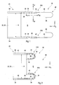
- exemplary embodiments of a pushing and / or pulling device 30 according to the invention for a vehicle top 20 each comprise two link chains 31A, 31B, which each have a plurality of link elements 34, 34A, 34B and run at a predetermined distance A from one another.
- the link chains 31A, 31B are each guided at one end in a guide 40 which predetermine a direction of movement R x1 , R x2 and the distance A of the link chains 31A, 31B from one another, and at the other end are connected to one another via a cross connection 32, so that the Link chains 31A, 31B run in a common plane E when leaving guide 40.
- two adjacent link elements 34, 34A, 34B of the link chains 31A, 31B are each movably connected to one another via a joint 36, 36A, 36B, so that at least some of the link elements 34, 34A, 34B move into the respective link chains 31A, 31B Guide 40 are stored in a corresponding tray 46.
- the adjacent link elements 34, 34A, 34B bear against each other when they leave the respective guide 40 and are supported against one another.
- pivot axes A Sa , A Sb between two adjacent link elements 34, 34A, 34B of the respective link chain 31A, 31B have a predetermined angle of inclination a a , a b to the common one Level E on.
- the pivot axes A Sa , A Sb of the two link chains 31A, 31B are inclined with respect to one another, so that the link chains 31A, 31B are cantilevered in the predetermined direction of movement R x1 , R x2 and mutually counter to other directions of movement R y1 , R y2 , R z1 , R z2 block.
- the predetermined directions of movement R x1 , R x2 run essentially parallel to the vehicle longitudinal direction x in the exemplary embodiments shown.
- the blocked directions of movement R y1 , R y2 , R z1 , R z2 run parallel to the vehicle transverse direction y and to the vehicle vertical direction.
- a self-supporting pushing and / or pulling device 30 with two link chains 31A, 31B can be represented, which simply roll up in the relaxed or flexible state and / or have it stowed in a shelf 46.
- the cantilever effect is determined by the distance A specified via the cross connection 32 at one end of the link chains 31A, 31B or by the distance between the link chains 31A, 31B when leaving the respective guide 40, which causes the link chains 31A, 31B to be mutually supported , and the adjacent link elements 34, 34A, 34B of the respective link chain 31A, 31B, which support one another after leaving the guide 40, are produced.
- the vehicle shown comprises on both sides of the vehicle a rear roof spar 2, a windshield 41 and an openable vehicle roof with a convertible top 20 according to the invention in Fig. 1 shown use position in a Fig. 2 shown Moved when not in use.
- a front convertible top section 22 is designed as a rigid roof tip, which is connected via at least one central part (not shown in more detail) to a rear rigid convertible top section 26 which has a rear window.
- the front convertible top section 22 forms the cross connection 32 between the two link chains 31A, 31B.
- the front convertible top section 22 can be arranged above or below the rear rigid convertible top section 26 in the non-use position.
- the adjacent link elements 34, 34A, 34B of the respective link chain 31A, 31B are connected to one another in such a way that they can only be pivoted relative to one another about a predetermined pivot axis A Sa , A Sb .
- the adjacent link elements 34, 34A, 34B of a second link chain 31B can likewise only pivot about a second pivot axis A Sb , so that the second link chain 31B can also only bend about these second pivot axes A Sb between adjacent link elements 34, 34A, 34B .
- the adjacent link elements 34, 34A, 34B of the link chains 31A, 31B stiffen against one another when a force acts in the opposite direction of the respective pivot axis A Sa , A Sb , since the adjacent link elements 34, 34A, 34B touch and thus prevent angling.
- the first link chain 31A blocks an angling of the second link chain 31B about the second pivot axes A Sb by the predetermined distance A, and the second link chain 31B blocks through the predetermined distance A angling the first link chain 31A about the first pivot axes A Sa.
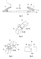
- the joint 36 in the illustrated embodiment is designed as an inexpensive hinge 36A with a fixed predetermined pivot axis A Sa , A Sb .
- the joint 36 in the illustrated embodiment is designed as a ball joint 36B with variable pivot axes.
- the adjacent link elements 34 connected via the ball joint 36B have guide contours 38.1, 38.2 which support the adjacent link elements 34 against one another when they leave the respective guide 40.
- a first guide contour 38.1 is designed as a depression with a triangular cross section
- a second guide contour 38.2 is designed as an elevation with a corresponding triangular cross section and is received by the depression.
- the angles of inclination a a , a b of the swivel axes A Sa , A Sb to the common plane E are each predetermined in a range of values greater than 0 ° and less than 180 °.
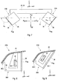
- the pivot axes A Sa , A Sb between the adjacent link elements 34, 34A, 34B are adapted to the conditions in the vehicle, in particular to the space available for the stored convertible top 20. So one in Fig. 7 shown first leg axis Asa between two adjacent link elements 34 of the first link chain 31A, which are connected via a hinge 36, for example a value of approximately 45 °.
- the second leg axis A Sb shown between two adjacent link elements 34 of the second link chain 31B, which are connected via a hinge 36, has a value of approximately 90 °, for example.
- the corresponding first leg axis A Sa (not shown) between two adjacent link elements 34 of the first link chain 31A then likewise has a value of approximately 90 °.
- One in Fig. 9 The illustrated second pivot axis A Sb between two adjacent link elements 34 of the second link chain 31B, which are connected via a hinge 36, has a value of approximately 60 °, for example.
- the corresponding first leg axis A Sa not shown, between two adjacent link elements 34 of the first link chain 31A then has a value of approximately 120 °.
- the individual link elements 34, 34A, 34B can have any shape.
- the individual link elements 34, 34A, 34B of the respective link chain 31A, 31B can have the same or different dimensions and / or shapes.
- the first link elements 34, 34A, 34B 34 of the respective link chain 31A, 31B, which are connected to the cross connection 32 can have a different shape and / or dimensions than the other link elements 34, 34A, 34B.
- Link elements 34 shown have, for example, a diamond-shaped cross section.
- Link elements 34A, 34B shown have, for example, different trapezoidal cross sections.
- the guide 40 in the illustrated embodiment comprises a load-bearing end section 42 and one Connecting section 44, which specifies a curved path for the corresponding link chain 31A, 31B between the load-bearing end section 42 and the shelf 46.
- the load-bearing end section 42, the connecting section 44 and the shelf 46 are each designed as guide rails which are arranged within the link elements 34, 34A, 34B.
- the load-bearing end section 42, the connecting section 44 and the shelf 46 can each be designed as guide rails which receive the link elements 34, 34A, 34B. Any combination is conceivable.
- the load bearing end portion 42 may be disposed within the link members 34, 34A, 34B, and the connecting portion 44 and tray 46 may receive the link members 34, 34A, 34B.
- the link elements 34A, 34B each have at least one guide element 34.1 in the exemplary embodiment shown, which is guided in the load-bearing end section 42 before leaving the guide 40.
- the guide element 34.1 is designed, for example, as a knob, which is guided in the load-bearing end section 42 designed as a guide rail.
- the guide element 34.1 is designed, for example, as a roller which rolls in the load-bearing end section 42 designed as a guide rail.
- the guide 40 has at least one drive element, which is coupled to a drive (not shown in more detail) and moves the respective link chain 31A, 31B.
- the at least one drive element can be designed, for example, as a pulling cable 39 or gear wheel or friction wheel or worm wheel or belt.
- a disk seal 34.2 with a receiving slot is arranged on the link elements 34A, 34B, in which a free edge of a side window can enter.
- a top fabric 24 closes the link elements 34A, 34B at the top when in use.
- Embodiments of the invention provide a self-supporting pushing and / or pulling device for a vehicle top with two link chains, which can be rolled up in the relaxed or flexible state and / or can be easily stowed in a storage compartment.
Landscapes
- Engineering & Computer Science (AREA)
- Mechanical Engineering (AREA)
- Body Structure For Vehicles (AREA)
- Fittings On The Vehicle Exterior For Carrying Loads, And Devices For Holding Or Mounting Articles (AREA)
Claims (17)
- Dispositif pour pousser et/ou tirer (30) destiné à une capote de véhicule (20), avec deux chaînes à maillons (31A, 31B), qui présentent chacune plusieurs maillons (34, 34A, 34B) et qui s'étendent avec une distance prédéterminée (A) l'une par rapport à l'autre, dans lequel les chaînes à maillons (31A, 31B) sont guidées chacune à une extrémité dans un guide (40), lequel prescrit un sens de déplacement (Rx1, Rx2) et la distance (A) des chaînes à maillons (31A, 31B) l'une par rapport à l'autre, et sont réunies à l'autre extrémité par l'intermédiaire d'une liaison transversale (32), de telle sorte que les chaînes à maillons (31A, 31B) s'étendent dans un plan commun (E) lorsqu'elles quittent le guide (40), dans lequel deux maillons voisins (34, 34A, 34B) des chaînes à maillons (31A, 31B) sont réunis de façon mobile à chaque fois par l'intermédiaire d'une articulation (36, 36A, 36B), de telle sorte qu'au moins une partie des maillons (34, 34A, 34B) est déposée dans un logement correspondant (46) lorsque les chaînes à maillons (31A, 31B) sont introduites dans le guide respectif (40), et dans lequel les maillons voisins (34, 34A, 34B) sont adjacents les uns aux autres et se soutiennent les uns contre les autres lorsqu'ils quittent le guide respectif (40), caractérisé en ce que des axes de pivotement (ASa, ASb) entre deux maillons voisins (34, 34A, 34B) de la chaîne à maillons (31A, 31B) respective présentent un angle d'inclinaison prédéterminé (aa, ab) par rapport au plan commun (E), dans lequel les axes de pivotement (ASa, ASb) des deux chaînes à maillons (31A, 31B) sont inclinés l'un par rapport à l'autre, de telle sorte que les chaînes à maillons (31A, 31B) s'étendent de manière non soutenue dans le sens de déplacement (Rx1, Rx2) prédéterminé et se bloquent mutuellement contre d'autres sens de déplacement (Ry1, Ry2, Rz1, Rz2).
- Dispositif pour pousser et/ou tirer selon la revendication 1, caractérisé en ce que les angles d'inclinaison (aa, ab) des axes de pivotement (ASa, ASb) par rapport au plan commun (E) sont prédéterminés à chaque fois dans une plage de valeurs supérieures à 0° et inférieures à 180°.
- Dispositif pour pousser et/ou tirer selon la revendication 1 ou 2, caractérisé en ce que l'articulation (36) est réalisée comme une charnière (36A) avec un axe de pivotement (ASa, ASb) prédéterminé fixe ou comme une articulation sphérique (36B) avec des axes de pivotement variables.
- Dispositif pour pousser et/ou tirer selon la revendication 3, caractérisé en ce que les maillons voisins (34) reliés par l'intermédiaire d'une articulation sphérique (36B) présentent des contours de guidage (38.1, 38.2) qui soutiennent les maillons voisins (34) les uns contre les autres lorsqu'ils quittent le guide (40) respectif.
- Dispositif pour pousser et/ou tirer selon la revendication 4, caractérisé en ce qu'un premier contour de guidage (38.1) est réalisé comme un creux et un deuxième contour de guidage (38.2) comme une bosse.
- Dispositif pour pousser et/ou tirer selon l'une quelconque des revendications 1 à 5, caractérisé en ce que le guide (40) présente au moins un élément d'entraînement qui est couplé à un entraînement et qui déplace la chaîne à maillons (31A, 31B) respective.
- Dispositif pour pousser et/ou tirer selon la revendication 6, caractérisé en ce que l'au moins un élément d'entraînement est réalisé comme un câble de traction (39) ou une roue dentée ou un galet de friction ou une roue tangente ou une courroie.
- Dispositif pour pousser et/ou tirer selon l'une quelconque des revendications 1 à 6, caractérisé en ce que le guide (40) comprend un tronçon terminal (42) porteur de charge et un tronçon de liaison (44) qui définit une trajectoire courbe pour la chaîne à maillons (31A, 31B) correspondante entre le tronçon terminal (42) porteur de charge et le logement (46).
- Dispositif pour pousser et/ou tirer selon la revendication 8, caractérisé en ce que le tronçon terminal (42) porteur de charge et/ou le tronçon de liaison (44) et/ou le logement (46) sont réalisés comme des rails de guidage qui sont agencés à l'intérieur des maillons (34, 34A, 34B).
- Dispositif pour pousser et/ou tirer selon la revendication 8 ou 9, caractérisé en ce que le tronçon terminal (42) porteur de charge et/ou le tronçon de liaison (42) et/ou le logement (46) sont réalisés comme des rails de guidage qui reçoivent les maillons (34, 34A, 34B).
- Dispositif pour pousser et/ou tirer selon l'une quelconque des revendications 8 à 10, caractérisé en ce que les maillons (34, 34A, 34B) présentent chacun au moins un élément de guidage (34.1) qui est guidé dans le tronçon terminal (42) porteur de charge avant de quitter le guide (40).
- Dispositif pour pousser et/ou tirer selon l'une quelconque des revendications 1 à 11, caractérisé en ce que les maillons individuels (34, 34A, 34B) de la chaîne à maillons (31A, 31B) respective présentent des dimensions et/ou des formes identiques ou différentes.
- Capote (20) pour un toit de véhicule ouvrant, qui présente plusieurs parties de capote et un dispositif pour pousser et/ou tirer (30) qui déplace les parties de capote d'une position d'usage à une position de non-usage, caractérisée en ce que le dispositif pour pousser et/ou tirer (30) est réalisé selon au moins l'une quelconque des revendications 1 à 12.
- Capote selon la revendication 13, caractérisée en ce qu'une partie de capote (22) avant est réalisée comme un sommet de toit rigide qui est relié par l'intermédiaire d'au moins une partie centrale à une partie de capote (26) arrière rigide qui présente une lunette arrière.
- Capote selon la revendication 14, caractérisée en ce que la partie de capote (22) avant constitue la liaison transversale (32) entre les deux chaînes à maillons (31A, 31B).
- Capote selon la revendication 14 ou 15, caractérisée en ce que, dans la position de non-usage, la partie de capote (22) avant est agencée au-dessus ou au-dessous de la partie de capote (26) arrière rigide.
- Capote selon l'une quelconque des revendications 13 à 16, caractérisée en ce qu'au niveau des maillons (34A, 34B) est agencé à chaque fois un joint de vitre (34.2) avec une fente de réception dans laquelle peut être introduit un bord libre d'une vitre latérale.
Applications Claiming Priority (2)
| Application Number | Priority Date | Filing Date | Title |
|---|---|---|---|
| DE102015015064.2A DE102015015064B4 (de) | 2015-11-20 | 2015-11-20 | Schub- und/oder Zugvorrichtung für ein Fahrzeugverdeck und Verdeck für ein öffnungsfähiges Fahrzeugdach |
| PCT/EP2016/001806 WO2017084739A1 (fr) | 2015-11-20 | 2016-10-28 | Dispositif de poussée et/ou de traction pour capote de véhicule et capote pour toit ouvrant de véhicule |
Publications (2)
| Publication Number | Publication Date |
|---|---|
| EP3377348A1 EP3377348A1 (fr) | 2018-09-26 |
| EP3377348B1 true EP3377348B1 (fr) | 2020-06-17 |
Family
ID=57209420
Family Applications (1)
| Application Number | Title | Priority Date | Filing Date |
|---|---|---|---|
| EP16788026.9A Active EP3377348B1 (fr) | 2015-11-20 | 2016-10-28 | Dispositif de poussée et/ou de traction pour capote de véhicule et capote pour toit ouvrant de véhicule |
Country Status (5)
| Country | Link |
|---|---|
| US (1) | US20180134133A1 (fr) |
| EP (1) | EP3377348B1 (fr) |
| CN (1) | CN107635810A (fr) |
| DE (1) | DE102015015064B4 (fr) |
| WO (1) | WO2017084739A1 (fr) |
Family Cites Families (16)
| Publication number | Priority date | Publication date | Assignee | Title |
|---|---|---|---|---|
| DE530694C (de) * | 1929-01-29 | 1931-08-01 | Saurer Ag Adolph | Zusammenlegbares Fahrzeugverdeck |
| DE4041763C1 (fr) | 1990-12-24 | 1992-02-13 | Webasto Ag Fahrzeugtechnik, 8035 Stockdorf, De | |
| FR2689466B1 (fr) | 1992-04-01 | 1994-07-01 | Mahaut Michel | Dispositif escamotable de bachage et de debachage d'un espace bi ou tridimensionnel. |
| DE4445580C1 (de) * | 1994-12-20 | 1995-12-21 | Daimler Benz Ag | Hardtop-Fahrzeug |
| DE19704846A1 (de) | 1997-02-08 | 1998-08-13 | Bayerische Motoren Werke Ag | Verdeck für ein motorisiertes Personenkleinfahrzeug |
| DE29706739U1 (de) * | 1997-04-15 | 1997-06-12 | Grasl, Andreas, Ing., Heiligeneich | Einrichtung zur Übertragung einer Kraft, insbesondere Druckkraft, längs einer im wesentlichen geraden Strecke |
| DE10120358C5 (de) | 2001-04-26 | 2007-05-16 | Karmann Gmbh W | Fahrzeug mit einem zu öffnenden Verdeck |
| DE10131892C2 (de) | 2001-07-04 | 2003-06-18 | Cts Fahrzeug Dachsysteme Gmbh | Abdeckung für einen Verdeckkasten zur Aufnahme eines verstellbaren Fahrzeugdaches |
| IES20020132A2 (en) * | 2002-02-21 | 2003-04-16 | Simon Betson | An actuator |
| DE102004003021A1 (de) | 2004-01-20 | 2005-08-04 | Wilhelm Karmann Gmbh | Cabriolet-Fahrzeug |
| FR2870789B1 (fr) * | 2004-05-25 | 2008-09-19 | France Design Sa | Toit repliable avec systeme de verrouillage pour un vehicule convertible |
| US7163260B2 (en) * | 2004-06-17 | 2007-01-16 | Asc Incorporated | Automotive vehicle open air system |
| ITMI20061026A1 (it) * | 2006-05-25 | 2007-11-26 | Autotek Srl | Gruppo per la movimentazione di tendine e simili particolarmente su autoveicoli |
| DE102012002298A1 (de) * | 2012-02-07 | 2013-08-08 | Magna Car Top Systems Gmbh | Öffnungsfähiges Fahrzeugdach für ein Cabriolet-Fahrzeug |
| DE102014010962A1 (de) * | 2014-07-25 | 2016-01-28 | Audi Ag | Verdeck für ein öffnungsfähiges Fahrzeugdach |
| DE102017102598B4 (de) * | 2016-05-17 | 2026-02-05 | Webasto SE | Verdeck eines Cabriolet-Fahrzeugs mit Flächenspriegeln |
-
2015
- 2015-11-20 DE DE102015015064.2A patent/DE102015015064B4/de not_active Expired - Fee Related
-
2016
- 2016-10-28 EP EP16788026.9A patent/EP3377348B1/fr active Active
- 2016-10-28 CN CN201680030161.2A patent/CN107635810A/zh not_active Withdrawn
- 2016-10-28 WO PCT/EP2016/001806 patent/WO2017084739A1/fr not_active Ceased
- 2016-10-28 US US15/572,892 patent/US20180134133A1/en not_active Abandoned
Non-Patent Citations (1)
| Title |
|---|
| None * |
Also Published As
| Publication number | Publication date |
|---|---|
| US20180134133A1 (en) | 2018-05-17 |
| EP3377348A1 (fr) | 2018-09-26 |
| DE102015015064A1 (de) | 2017-05-24 |
| WO2017084739A1 (fr) | 2017-05-26 |
| DE102015015064B4 (de) | 2019-10-02 |
| CN107635810A (zh) | 2018-01-26 |
Similar Documents
| Publication | Publication Date | Title |
|---|---|---|
| DE60007880T2 (de) | Versenkbares dachsystem und damit ausgerüstetes fahrzeug | |
| WO2014001013A1 (fr) | Dispositif de réglage de la position d'un pare-brise | |
| WO2013170993A1 (fr) | Toit de véhicule comprenant deux éléments de panneau | |
| DE10329536B4 (de) | Fahrzeugdach | |
| DE10002457C2 (de) | Schiebedach | |
| EP1790515A1 (fr) | Mécanisme pour soulever un toit ouvrant et un toit de véhicule avec tel mécanisme | |
| WO2024115762A1 (fr) | Segment de battant de porte divisible | |
| EP0309775A2 (fr) | Toit ouvrant pour véhicules automobiles | |
| EP1758749A1 (fr) | Vehicule cabriolet | |
| EP2977247A1 (fr) | Capote pour toit ouvrant de véhicule | |
| WO2018137749A1 (fr) | Véhicule automobile | |
| DE102013111566B4 (de) | Windabweiser | |
| DE102008058242A1 (de) | Schiebetüranordnung | |
| DE102014219920B4 (de) | Faltverdeck für Kraftfahrzeuge | |
| DE10057167C2 (de) | Fahrzeugdach mit wenigstens zwei hintereinander angeordneten Deckeln | |
| DE4328886C2 (de) | Cabriolet mit einem Fondstauraum | |
| EP1379402B1 (fr) | Toit a lamelles | |
| DE19856873C1 (de) | Lamellendach für eine Dachöffnung eines Kraftfahrzeugs | |
| DE19842824A1 (de) | Sitzanordnung in einem Fahrzeug | |
| EP1651457A1 (fr) | Ensemble store pour la fenetre d'un vehicule a moteur | |
| DE602004007000T2 (de) | Schiebedachsystem mit stapelbaren platten und damit ausgestattetes fahrzeug | |
| DE102015015064B4 (de) | Schub- und/oder Zugvorrichtung für ein Fahrzeugverdeck und Verdeck für ein öffnungsfähiges Fahrzeugdach | |
| DE102004005755B3 (de) | Öffnungsfähiges Fahrzeugdach | |
| DE3211467C2 (de) | Öffnungssystem für Schiebedach, insbesondere für Kraftfahrzeuge | |
| DE102020109674B3 (de) | Abdeckvorrichtung und Aufnahmevorrichtung für ein Fahrzeug |
Legal Events
| Date | Code | Title | Description |
|---|---|---|---|
| STAA | Information on the status of an ep patent application or granted ep patent |
Free format text: STATUS: UNKNOWN |
|
| STAA | Information on the status of an ep patent application or granted ep patent |
Free format text: STATUS: THE INTERNATIONAL PUBLICATION HAS BEEN MADE |
|
| PUAI | Public reference made under article 153(3) epc to a published international application that has entered the european phase |
Free format text: ORIGINAL CODE: 0009012 |
|
| STAA | Information on the status of an ep patent application or granted ep patent |
Free format text: STATUS: REQUEST FOR EXAMINATION WAS MADE |
|
| 17P | Request for examination filed |
Effective date: 20180620 |
|
| AK | Designated contracting states |
Kind code of ref document: A1 Designated state(s): AL AT BE BG CH CY CZ DE DK EE ES FI FR GB GR HR HU IE IS IT LI LT LU LV MC MK MT NL NO PL PT RO RS SE SI SK SM TR |
|
| AX | Request for extension of the european patent |
Extension state: BA ME |
|
| DAV | Request for validation of the european patent (deleted) | ||
| DAX | Request for extension of the european patent (deleted) | ||
| GRAP | Despatch of communication of intention to grant a patent |
Free format text: ORIGINAL CODE: EPIDOSNIGR1 |
|
| STAA | Information on the status of an ep patent application or granted ep patent |
Free format text: STATUS: GRANT OF PATENT IS INTENDED |
|
| INTG | Intention to grant announced |
Effective date: 20200407 |
|
| GRAS | Grant fee paid |
Free format text: ORIGINAL CODE: EPIDOSNIGR3 |
|
| GRAA | (expected) grant |
Free format text: ORIGINAL CODE: 0009210 |
|
| STAA | Information on the status of an ep patent application or granted ep patent |
Free format text: STATUS: THE PATENT HAS BEEN GRANTED |
|
| AK | Designated contracting states |
Kind code of ref document: B1 Designated state(s): AL AT BE BG CH CY CZ DE DK EE ES FI FR GB GR HR HU IE IS IT LI LT LU LV MC MK MT NL NO PL PT RO RS SE SI SK SM TR |
|
| REG | Reference to a national code |
Ref country code: GB Ref legal event code: FG4D Free format text: NOT ENGLISH |
|
| REG | Reference to a national code |
Ref country code: CH Ref legal event code: EP |
|
| REG | Reference to a national code |
Ref country code: IE Ref legal event code: FG4D Free format text: LANGUAGE OF EP DOCUMENT: GERMAN |
|
| REG | Reference to a national code |
Ref country code: DE Ref legal event code: R096 Ref document number: 502016010274 Country of ref document: DE |
|
| REG | Reference to a national code |
Ref country code: AT Ref legal event code: REF Ref document number: 1280887 Country of ref document: AT Kind code of ref document: T Effective date: 20200715 |
|
| PG25 | Lapsed in a contracting state [announced via postgrant information from national office to epo] |
Ref country code: SE Free format text: LAPSE BECAUSE OF FAILURE TO SUBMIT A TRANSLATION OF THE DESCRIPTION OR TO PAY THE FEE WITHIN THE PRESCRIBED TIME-LIMIT Effective date: 20200617 Ref country code: LT Free format text: LAPSE BECAUSE OF FAILURE TO SUBMIT A TRANSLATION OF THE DESCRIPTION OR TO PAY THE FEE WITHIN THE PRESCRIBED TIME-LIMIT Effective date: 20200617 Ref country code: NO Free format text: LAPSE BECAUSE OF FAILURE TO SUBMIT A TRANSLATION OF THE DESCRIPTION OR TO PAY THE FEE WITHIN THE PRESCRIBED TIME-LIMIT Effective date: 20200917 Ref country code: GR Free format text: LAPSE BECAUSE OF FAILURE TO SUBMIT A TRANSLATION OF THE DESCRIPTION OR TO PAY THE FEE WITHIN THE PRESCRIBED TIME-LIMIT Effective date: 20200918 Ref country code: FI Free format text: LAPSE BECAUSE OF FAILURE TO SUBMIT A TRANSLATION OF THE DESCRIPTION OR TO PAY THE FEE WITHIN THE PRESCRIBED TIME-LIMIT Effective date: 20200617 |
|
| REG | Reference to a national code |
Ref country code: LT Ref legal event code: MG4D |
|
| REG | Reference to a national code |
Ref country code: NL Ref legal event code: MP Effective date: 20200617 |
|
| PG25 | Lapsed in a contracting state [announced via postgrant information from national office to epo] |
Ref country code: LV Free format text: LAPSE BECAUSE OF FAILURE TO SUBMIT A TRANSLATION OF THE DESCRIPTION OR TO PAY THE FEE WITHIN THE PRESCRIBED TIME-LIMIT Effective date: 20200617 Ref country code: HR Free format text: LAPSE BECAUSE OF FAILURE TO SUBMIT A TRANSLATION OF THE DESCRIPTION OR TO PAY THE FEE WITHIN THE PRESCRIBED TIME-LIMIT Effective date: 20200617 Ref country code: BG Free format text: LAPSE BECAUSE OF FAILURE TO SUBMIT A TRANSLATION OF THE DESCRIPTION OR TO PAY THE FEE WITHIN THE PRESCRIBED TIME-LIMIT Effective date: 20200917 Ref country code: RS Free format text: LAPSE BECAUSE OF FAILURE TO SUBMIT A TRANSLATION OF THE DESCRIPTION OR TO PAY THE FEE WITHIN THE PRESCRIBED TIME-LIMIT Effective date: 20200617 |
|
| PG25 | Lapsed in a contracting state [announced via postgrant information from national office to epo] |
Ref country code: NL Free format text: LAPSE BECAUSE OF FAILURE TO SUBMIT A TRANSLATION OF THE DESCRIPTION OR TO PAY THE FEE WITHIN THE PRESCRIBED TIME-LIMIT Effective date: 20200617 Ref country code: AL Free format text: LAPSE BECAUSE OF FAILURE TO SUBMIT A TRANSLATION OF THE DESCRIPTION OR TO PAY THE FEE WITHIN THE PRESCRIBED TIME-LIMIT Effective date: 20200617 |
|
| PG25 | Lapsed in a contracting state [announced via postgrant information from national office to epo] |
Ref country code: RO Free format text: LAPSE BECAUSE OF FAILURE TO SUBMIT A TRANSLATION OF THE DESCRIPTION OR TO PAY THE FEE WITHIN THE PRESCRIBED TIME-LIMIT Effective date: 20200617 Ref country code: CZ Free format text: LAPSE BECAUSE OF FAILURE TO SUBMIT A TRANSLATION OF THE DESCRIPTION OR TO PAY THE FEE WITHIN THE PRESCRIBED TIME-LIMIT Effective date: 20200617 Ref country code: PT Free format text: LAPSE BECAUSE OF FAILURE TO SUBMIT A TRANSLATION OF THE DESCRIPTION OR TO PAY THE FEE WITHIN THE PRESCRIBED TIME-LIMIT Effective date: 20201019 Ref country code: ES Free format text: LAPSE BECAUSE OF FAILURE TO SUBMIT A TRANSLATION OF THE DESCRIPTION OR TO PAY THE FEE WITHIN THE PRESCRIBED TIME-LIMIT Effective date: 20200617 Ref country code: EE Free format text: LAPSE BECAUSE OF FAILURE TO SUBMIT A TRANSLATION OF THE DESCRIPTION OR TO PAY THE FEE WITHIN THE PRESCRIBED TIME-LIMIT Effective date: 20200617 Ref country code: SM Free format text: LAPSE BECAUSE OF FAILURE TO SUBMIT A TRANSLATION OF THE DESCRIPTION OR TO PAY THE FEE WITHIN THE PRESCRIBED TIME-LIMIT Effective date: 20200617 Ref country code: IT Free format text: LAPSE BECAUSE OF FAILURE TO SUBMIT A TRANSLATION OF THE DESCRIPTION OR TO PAY THE FEE WITHIN THE PRESCRIBED TIME-LIMIT Effective date: 20200617 |
|
| PG25 | Lapsed in a contracting state [announced via postgrant information from national office to epo] |
Ref country code: SK Free format text: LAPSE BECAUSE OF FAILURE TO SUBMIT A TRANSLATION OF THE DESCRIPTION OR TO PAY THE FEE WITHIN THE PRESCRIBED TIME-LIMIT Effective date: 20200617 Ref country code: PL Free format text: LAPSE BECAUSE OF FAILURE TO SUBMIT A TRANSLATION OF THE DESCRIPTION OR TO PAY THE FEE WITHIN THE PRESCRIBED TIME-LIMIT Effective date: 20200617 Ref country code: IS Free format text: LAPSE BECAUSE OF FAILURE TO SUBMIT A TRANSLATION OF THE DESCRIPTION OR TO PAY THE FEE WITHIN THE PRESCRIBED TIME-LIMIT Effective date: 20201017 |
|
| REG | Reference to a national code |
Ref country code: DE Ref legal event code: R097 Ref document number: 502016010274 Country of ref document: DE |
|
| PLBE | No opposition filed within time limit |
Free format text: ORIGINAL CODE: 0009261 |
|
| STAA | Information on the status of an ep patent application or granted ep patent |
Free format text: STATUS: NO OPPOSITION FILED WITHIN TIME LIMIT |
|
| PG25 | Lapsed in a contracting state [announced via postgrant information from national office to epo] |
Ref country code: DK Free format text: LAPSE BECAUSE OF FAILURE TO SUBMIT A TRANSLATION OF THE DESCRIPTION OR TO PAY THE FEE WITHIN THE PRESCRIBED TIME-LIMIT Effective date: 20200617 |
|
| 26N | No opposition filed |
Effective date: 20210318 |
|
| PG25 | Lapsed in a contracting state [announced via postgrant information from national office to epo] |
Ref country code: SI Free format text: LAPSE BECAUSE OF FAILURE TO SUBMIT A TRANSLATION OF THE DESCRIPTION OR TO PAY THE FEE WITHIN THE PRESCRIBED TIME-LIMIT Effective date: 20200617 |
|
| REG | Reference to a national code |
Ref country code: CH Ref legal event code: PL |
|
| GBPC | Gb: european patent ceased through non-payment of renewal fee |
Effective date: 20201028 |
|
| PG25 | Lapsed in a contracting state [announced via postgrant information from national office to epo] |
Ref country code: LU Free format text: LAPSE BECAUSE OF NON-PAYMENT OF DUE FEES Effective date: 20201028 Ref country code: MC Free format text: LAPSE BECAUSE OF FAILURE TO SUBMIT A TRANSLATION OF THE DESCRIPTION OR TO PAY THE FEE WITHIN THE PRESCRIBED TIME-LIMIT Effective date: 20200617 |
|
| REG | Reference to a national code |
Ref country code: BE Ref legal event code: MM Effective date: 20201031 |
|
| PG25 | Lapsed in a contracting state [announced via postgrant information from national office to epo] |
Ref country code: LI Free format text: LAPSE BECAUSE OF NON-PAYMENT OF DUE FEES Effective date: 20201031 Ref country code: GB Free format text: LAPSE BECAUSE OF NON-PAYMENT OF DUE FEES Effective date: 20201028 Ref country code: BE Free format text: LAPSE BECAUSE OF NON-PAYMENT OF DUE FEES Effective date: 20201031 Ref country code: CH Free format text: LAPSE BECAUSE OF NON-PAYMENT OF DUE FEES Effective date: 20201031 |
|
| PG25 | Lapsed in a contracting state [announced via postgrant information from national office to epo] |
Ref country code: IE Free format text: LAPSE BECAUSE OF NON-PAYMENT OF DUE FEES Effective date: 20201028 |
|
| PG25 | Lapsed in a contracting state [announced via postgrant information from national office to epo] |
Ref country code: TR Free format text: LAPSE BECAUSE OF FAILURE TO SUBMIT A TRANSLATION OF THE DESCRIPTION OR TO PAY THE FEE WITHIN THE PRESCRIBED TIME-LIMIT Effective date: 20200617 Ref country code: MT Free format text: LAPSE BECAUSE OF FAILURE TO SUBMIT A TRANSLATION OF THE DESCRIPTION OR TO PAY THE FEE WITHIN THE PRESCRIBED TIME-LIMIT Effective date: 20200617 Ref country code: CY Free format text: LAPSE BECAUSE OF FAILURE TO SUBMIT A TRANSLATION OF THE DESCRIPTION OR TO PAY THE FEE WITHIN THE PRESCRIBED TIME-LIMIT Effective date: 20200617 |
|
| PG25 | Lapsed in a contracting state [announced via postgrant information from national office to epo] |
Ref country code: MK Free format text: LAPSE BECAUSE OF FAILURE TO SUBMIT A TRANSLATION OF THE DESCRIPTION OR TO PAY THE FEE WITHIN THE PRESCRIBED TIME-LIMIT Effective date: 20200617 |
|
| REG | Reference to a national code |
Ref country code: AT Ref legal event code: MM01 Ref document number: 1280887 Country of ref document: AT Kind code of ref document: T Effective date: 20211028 |
|
| PG25 | Lapsed in a contracting state [announced via postgrant information from national office to epo] |
Ref country code: AT Free format text: LAPSE BECAUSE OF NON-PAYMENT OF DUE FEES Effective date: 20211028 |
|
| P01 | Opt-out of the competence of the unified patent court (upc) registered |
Effective date: 20230530 |
|
| PGFP | Annual fee paid to national office [announced via postgrant information from national office to epo] |
Ref country code: DE Payment date: 20241031 Year of fee payment: 9 |
|
| PGFP | Annual fee paid to national office [announced via postgrant information from national office to epo] |
Ref country code: FR Payment date: 20241023 Year of fee payment: 9 |