EP3375957A1 - Zuhaltevorrichtung - Google Patents
Zuhaltevorrichtung Download PDFInfo
- Publication number
- EP3375957A1 EP3375957A1 EP17161677.4A EP17161677A EP3375957A1 EP 3375957 A1 EP3375957 A1 EP 3375957A1 EP 17161677 A EP17161677 A EP 17161677A EP 3375957 A1 EP3375957 A1 EP 3375957A1
- Authority
- EP
- European Patent Office
- Prior art keywords
- locking device
- electric drive
- locking
- locking element
- actuator
- Prior art date
- Legal status (The legal status is an assumption and is not a legal conclusion. Google has not performed a legal analysis and makes no representation as to the accuracy of the status listed.)
- Granted
Links
- 230000008878 coupling Effects 0.000 claims abstract description 19
- 238000010168 coupling process Methods 0.000 claims abstract description 19
- 238000005859 coupling reaction Methods 0.000 claims abstract description 19
- 230000000903 blocking effect Effects 0.000 claims abstract description 13
- 230000001681 protective effect Effects 0.000 description 6
- 231100001261 hazardous Toxicity 0.000 description 2
- 238000006243 chemical reaction Methods 0.000 description 1
- 238000010276 construction Methods 0.000 description 1
- 230000001419 dependent effect Effects 0.000 description 1
- 238000011161 development Methods 0.000 description 1
- 230000018109 developmental process Effects 0.000 description 1
- 238000005516 engineering process Methods 0.000 description 1
- 210000003746 feather Anatomy 0.000 description 1
- 238000007689 inspection Methods 0.000 description 1
- 238000009434 installation Methods 0.000 description 1
- 238000000034 method Methods 0.000 description 1
Images

Classifications
-
- E—FIXED CONSTRUCTIONS
- E05—LOCKS; KEYS; WINDOW OR DOOR FITTINGS; SAFES
- E05B—LOCKS; ACCESSORIES THEREFOR; HANDCUFFS
- E05B47/00—Operating or controlling locks or other fastening devices by electric or magnetic means
- E05B47/0001—Operating or controlling locks or other fastening devices by electric or magnetic means with electric actuators; Constructional features thereof
- E05B47/0012—Operating or controlling locks or other fastening devices by electric or magnetic means with electric actuators; Constructional features thereof with rotary electromotors
-
- E—FIXED CONSTRUCTIONS
- E05—LOCKS; KEYS; WINDOW OR DOOR FITTINGS; SAFES
- E05B—LOCKS; ACCESSORIES THEREFOR; HANDCUFFS
- E05B47/00—Operating or controlling locks or other fastening devices by electric or magnetic means
- E05B47/02—Movement of the bolt by electromagnetic means; Adaptation of locks, latches, or parts thereof, for movement of the bolt by electromagnetic means
- E05B47/026—Movement of the bolt by electromagnetic means; Adaptation of locks, latches, or parts thereof, for movement of the bolt by electromagnetic means the bolt moving rectilinearly
-
- E—FIXED CONSTRUCTIONS
- E05—LOCKS; KEYS; WINDOW OR DOOR FITTINGS; SAFES
- E05B—LOCKS; ACCESSORIES THEREFOR; HANDCUFFS
- E05B65/00—Locks or fastenings for special use
- E05B65/10—Locks or fastenings for special use for panic or emergency doors
-
- E—FIXED CONSTRUCTIONS
- E05—LOCKS; KEYS; WINDOW OR DOOR FITTINGS; SAFES
- E05C—BOLTS OR FASTENING DEVICES FOR WINGS, SPECIALLY FOR DOORS OR WINDOWS
- E05C1/00—Fastening devices with bolts moving rectilinearly
- E05C1/002—Fastening devices with bolts moving rectilinearly perpendicular to the surface on which the fastener is mounted
-
- E—FIXED CONSTRUCTIONS
- E05—LOCKS; KEYS; WINDOW OR DOOR FITTINGS; SAFES
- E05C—BOLTS OR FASTENING DEVICES FOR WINGS, SPECIALLY FOR DOORS OR WINDOWS
- E05C1/00—Fastening devices with bolts moving rectilinearly
- E05C1/08—Fastening devices with bolts moving rectilinearly with latching action
-
- G—PHYSICS
- G06—COMPUTING; CALCULATING OR COUNTING
- G06K—GRAPHICAL DATA READING; PRESENTATION OF DATA; RECORD CARRIERS; HANDLING RECORD CARRIERS
- G06K7/00—Methods or arrangements for sensing record carriers, e.g. for reading patterns
- G06K7/10—Methods or arrangements for sensing record carriers, e.g. for reading patterns by electromagnetic radiation, e.g. optical sensing; by corpuscular radiation
- G06K7/10009—Methods or arrangements for sensing record carriers, e.g. for reading patterns by electromagnetic radiation, e.g. optical sensing; by corpuscular radiation sensing by radiation using wavelengths larger than 0.1 mm, e.g. radio-waves or microwaves
- G06K7/10366—Methods or arrangements for sensing record carriers, e.g. for reading patterns by electromagnetic radiation, e.g. optical sensing; by corpuscular radiation sensing by radiation using wavelengths larger than 0.1 mm, e.g. radio-waves or microwaves the interrogation device being adapted for miscellaneous applications
-
- E—FIXED CONSTRUCTIONS
- E05—LOCKS; KEYS; WINDOW OR DOOR FITTINGS; SAFES
- E05B—LOCKS; ACCESSORIES THEREFOR; HANDCUFFS
- E05B15/00—Other details of locks; Parts for engagement by bolts of fastening devices
- E05B15/02—Striking-plates; Keepers; Bolt staples; Escutcheons
- E05B15/0205—Striking-plates, keepers, staples
- E05B2015/023—Keeper shape
-
- E—FIXED CONSTRUCTIONS
- E05—LOCKS; KEYS; WINDOW OR DOOR FITTINGS; SAFES
- E05B—LOCKS; ACCESSORIES THEREFOR; HANDCUFFS
- E05B47/00—Operating or controlling locks or other fastening devices by electric or magnetic means
- E05B47/0001—Operating or controlling locks or other fastening devices by electric or magnetic means with electric actuators; Constructional features thereof
- E05B2047/0014—Constructional features of actuators or power transmissions therefor
- E05B2047/0015—Output elements of actuators
- E05B2047/0017—Output elements of actuators with rotary motion
-
- E—FIXED CONSTRUCTIONS
- E05—LOCKS; KEYS; WINDOW OR DOOR FITTINGS; SAFES
- E05B—LOCKS; ACCESSORIES THEREFOR; HANDCUFFS
- E05B47/00—Operating or controlling locks or other fastening devices by electric or magnetic means
- E05B47/0001—Operating or controlling locks or other fastening devices by electric or magnetic means with electric actuators; Constructional features thereof
- E05B2047/0014—Constructional features of actuators or power transmissions therefor
- E05B2047/0018—Details of actuator transmissions
- E05B2047/002—Geared transmissions
- E05B2047/0022—Planetary gears
-
- E—FIXED CONSTRUCTIONS
- E05—LOCKS; KEYS; WINDOW OR DOOR FITTINGS; SAFES
- E05B—LOCKS; ACCESSORIES THEREFOR; HANDCUFFS
- E05B47/00—Operating or controlling locks or other fastening devices by electric or magnetic means
- E05B47/0001—Operating or controlling locks or other fastening devices by electric or magnetic means with electric actuators; Constructional features thereof
- E05B2047/0014—Constructional features of actuators or power transmissions therefor
- E05B2047/0018—Details of actuator transmissions
- E05B2047/0023—Nuts or nut-like elements moving along a driven threaded axle
-
- E—FIXED CONSTRUCTIONS
- E05—LOCKS; KEYS; WINDOW OR DOOR FITTINGS; SAFES
- E05B—LOCKS; ACCESSORIES THEREFOR; HANDCUFFS
- E05B47/00—Operating or controlling locks or other fastening devices by electric or magnetic means
- E05B47/0001—Operating or controlling locks or other fastening devices by electric or magnetic means with electric actuators; Constructional features thereof
- E05B2047/0014—Constructional features of actuators or power transmissions therefor
- E05B2047/0036—Reversible actuators
-
- E—FIXED CONSTRUCTIONS
- E05—LOCKS; KEYS; WINDOW OR DOOR FITTINGS; SAFES
- E05B—LOCKS; ACCESSORIES THEREFOR; HANDCUFFS
- E05B47/00—Operating or controlling locks or other fastening devices by electric or magnetic means
- E05B2047/0048—Circuits, feeding, monitoring
- E05B2047/0067—Monitoring
- E05B2047/0069—Monitoring bolt position
-
- E—FIXED CONSTRUCTIONS
- E05—LOCKS; KEYS; WINDOW OR DOOR FITTINGS; SAFES
- E05B—LOCKS; ACCESSORIES THEREFOR; HANDCUFFS
- E05B47/00—Operating or controlling locks or other fastening devices by electric or magnetic means
- E05B2047/0072—Operation
- E05B2047/0081—Same pulse to lock or unlock
-
- E—FIXED CONSTRUCTIONS
- E05—LOCKS; KEYS; WINDOW OR DOOR FITTINGS; SAFES
- E05B—LOCKS; ACCESSORIES THEREFOR; HANDCUFFS
- E05B47/00—Operating or controlling locks or other fastening devices by electric or magnetic means
- E05B2047/0084—Key or electric means; Emergency release
- E05B2047/0086—Emergency release, e.g. key or electromagnet
-
- E—FIXED CONSTRUCTIONS
- E05—LOCKS; KEYS; WINDOW OR DOOR FITTINGS; SAFES
- E05B—LOCKS; ACCESSORIES THEREFOR; HANDCUFFS
- E05B65/00—Locks or fastenings for special use
-
- E—FIXED CONSTRUCTIONS
- E05—LOCKS; KEYS; WINDOW OR DOOR FITTINGS; SAFES
- E05Y—INDEXING SCHEME ASSOCIATED WITH SUBCLASSES E05D AND E05F, RELATING TO CONSTRUCTION ELEMENTS, ELECTRIC CONTROL, POWER SUPPLY, POWER SIGNAL OR TRANSMISSION, USER INTERFACES, MOUNTING OR COUPLING, DETAILS, ACCESSORIES, AUXILIARY OPERATIONS NOT OTHERWISE PROVIDED FOR, APPLICATION THEREOF
- E05Y2201/00—Constructional elements; Accessories therefor
- E05Y2201/40—Motors; Magnets; Springs; Weights; Accessories therefor
- E05Y2201/43—Motors
- E05Y2201/434—Electromotors; Details thereof
-
- E—FIXED CONSTRUCTIONS
- E05—LOCKS; KEYS; WINDOW OR DOOR FITTINGS; SAFES
- E05Y—INDEXING SCHEME ASSOCIATED WITH SUBCLASSES E05D AND E05F, RELATING TO CONSTRUCTION ELEMENTS, ELECTRIC CONTROL, POWER SUPPLY, POWER SIGNAL OR TRANSMISSION, USER INTERFACES, MOUNTING OR COUPLING, DETAILS, ACCESSORIES, AUXILIARY OPERATIONS NOT OTHERWISE PROVIDED FOR, APPLICATION THEREOF
- E05Y2201/00—Constructional elements; Accessories therefor
- E05Y2201/60—Suspension or transmission members; Accessories therefor
- E05Y2201/622—Suspension or transmission members elements
- E05Y2201/71—Toothed gearing
- E05Y2201/72—Planetary gearing
-
- E—FIXED CONSTRUCTIONS
- E05—LOCKS; KEYS; WINDOW OR DOOR FITTINGS; SAFES
- E05Y—INDEXING SCHEME ASSOCIATED WITH SUBCLASSES E05D AND E05F, RELATING TO CONSTRUCTION ELEMENTS, ELECTRIC CONTROL, POWER SUPPLY, POWER SIGNAL OR TRANSMISSION, USER INTERFACES, MOUNTING OR COUPLING, DETAILS, ACCESSORIES, AUXILIARY OPERATIONS NOT OTHERWISE PROVIDED FOR, APPLICATION THEREOF
- E05Y2900/00—Application of doors, windows, wings or fittings thereof
- E05Y2900/10—Application of doors, windows, wings or fittings thereof for buildings or parts thereof
- E05Y2900/13—Type of wing
- E05Y2900/132—Doors
Definitions
- the invention relates to a locking device according to the preamble of claim 1.
- safety switches are known to be used to secure access to hazardous areas.
- a safety switch a lock of a safety door can be secured as access to a danger area.
- the operation of a hazardous installation within the danger zone is only enabled by a safety controller if the safety door is locked with the safety switch.
- the safety switch here is assigned an actuator.
- the actuator can typically be arranged on the protective door, while the safety switch is arranged on a frame delimiting the door opening.
- the actuator is brought into engagement with the safety switch, for example, by the actuator is retracted into a recess.
- This lock is controlled by detecting a transponder in the actuator with an RFID reader in the safety switch.
- a guard locking of the protective door may be provided.
- a tumbler is for example from the WO 2016/058718 A1 known.
- a Zuhaltebolzen is provided which is actuated by means of an electric motor with a planetary gear. With the electric drive the Zuhaltebolzen can be moved into a blocking position in which the actuator is locked with the Zuhaltebolzen.
- the invention has for its object to provide a locking device of the type mentioned, which has a high functionality.
- the invention relates to an actuatable by means of an electric drive locking element.
- the locking element can be introduced in such a blocking position that an actuator of a safety switch is locked with this.
- the tumbler element is connected to the electric drive via a coupling so that a rotational movement of the electric drive is converted into a pure translational movement of the tumbler element.
- an essential aspect of the invention is that with the coupling and preferably a spindle nut on a driven by the electric drive spindle, a conversion of the rotational movement of the electrical Anriebs is converted into a pure translational movement of the locking element.
- a bistable tumbler is feasible.
- the locking element By means of the electric drive, the locking element can be inserted into the locking position. In this, the locking element engages in a recording of the actuator whereby the tumbler is effected.
- the locking element By means of the electric drive, the locking element can be extended again from the locked position.
- the movement control of the tumbler is complete via the electric drive.
- the locking element In order to be able to hold the actuator with the locking element, the locking element is moved in advance into its release position by means of the electric drive, so that the actuator can be introduced unhindered with its inclusion in the region of the locking element. Then, the locking element is moved by means of the electric drive in the blocking position, whereby the tumbler is realized.
- this decoupling means by means of which the locking element is decoupled from the electric drive against a spring force from the locking position out movable.
- the locking device which can be used for an escape release such that when the locking device, for example, a guard is locked, which blocks access to a danger zone, a person who resides in the danger zone, the Manually unlock the safety door to be able to move out of the danger zone.
- the mechanical unlocking can also be actuated from the outside of the protective door, that is to say by a person outside the danger zone, in order to carry out an auxiliary unlocking in an inspection area of the respective safety device or an emergency unlocking of the protective door.
- the decoupling means are used to realize a catching function.
- the catch function is realized in that by means of an engagement element of the actuator, the tumbler is moved mechanically and decoupled from the electric drive from a blocking position. If the recording of the actuator is in the region of the tumbler element, this is moved back by the spring force in the blocking position and engages in the receptacle of the actuator.
- This catch function is an alternative to bistable tumbler.
- the movement of the tumbler element is not completely controlled by the electric drive in the catch function. Rather, the decoupling means are shared for mechanical decoupling.
- the locking device is operable either with a bistable tumbler or a catch function.
- the functionality of the bistable tumbler or the catching function is defined by a software version of the locking device or can be predetermined by a programming command.
- the clutch has a transverse pin and a cylinder pin extending transversely thereto, wherein the transverse pin is guided in a longitudinal guide and wherein the cylindrical pin secures the transverse pin.
- the thus formed coupling has a very simple structure with few parts.
- the longitudinal axes of the transverse pin and the cylindrical pin extend transversely to the longitudinal axis of the locking element, wherein the transverse pin is mounted with play in a recess of the locking element and wherein the cylinder pin is mounted with clearance in a recess of the transverse pin.
- the tumbler according to the invention is insensitive to unavoidable component tolerances, whereby the reliability of the locking device is increased.
- the electric drive has an electric motor with a planetary gear.
- a spindle is provided on the electric drive, which carries out a feed movement by the rotational movement of the electric drive, which is converted to a coupled by means of a spindle nut to the spindle driver, which is coupled via the coupling with the locking element.
- the driver is connected by means of the cylindrical pin with the clutch and thus stored against infeed.
- the locking device formed in this way has a compact, robust construction.
- the driver is formed as a hollow cylinder, wherein the interior of the driver forms a decoupling path as part of the decoupling means, wherein the spindle along the decoupling path is feasible.
- a spring force-generating spring is mounted between the driver and the decoupling means.
- a cable is guided within the tumbler element, wherein on the tumbler element a cable deflection is arranged, by means of which the cable is positively guided along a trajectory.
- the cable is connected to a built-in Zuhalteelement sensor means for controlling the tumbler.
- the opening at the cable deflection cable is guided laterally next to the components of the locking device.
- the locking element in a release position corresponding lower end position can be introduced, which is controllable by means of a sensor.
- the locking element can be introduced into a release position corresponding lower end position, which is controllable by means of a sensor. This determines the lower position of the spindle nut. Based on this, the other positions of the spindle nut are determined by means of a rotary encoder of the electric drive.
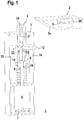
- FIG. 1 shows an embodiment of the locking device according to the invention 1.
- the locking device 1 is used to lock an actuator 2, which is part of a safety device with a safety switch, not shown.
- the actuator 2 can be arranged on the safety door
- the safety switch can be arranged on a frame delimiting the door opening, which is closed with the safety door.
- the closed position of a protective door is controlled by an RFID reader in the safety switch reading the coded signal of a transponder in the actuator.
- the locking device 1 has a housing 3 for receiving its individual components.
- a locking element 4 which is formed in the present case by a Zuhaltebolzen be extended over an opening at the top of the housing 3 and retracted into a recess 5 on the underside of the actuator 2.
- an electric drive 6 is mounted, which has an electric motor with a planetary gear.
- the current rotational position of the electric motor is detected by a rotary encoder 7.
- a spindle 8 is driven.
- the front end of the spindle 8 is connected to a driver 9.
- the driver 9 is formed as a hollow cylinder.
- the front end of the spindle 8 projects beyond the underside of the driver 9 in its interior and is supported there by means of a spindle nut 10.
- the locking element 4 is coupled by means of a coupling 11 to the upper end of the driver 9.
- a rotational movement of the driven by the electric drive 6 spindle 8 is converted by the clutch 11 and the spindle nut 10 in a pure translational movement of the locking element 4.
- This coupling 11 has a transverse pin 12 and a cylindrical pin 13, whose longitudinal axes are oriented perpendicular to each other and each perpendicular to the longitudinal axis of the driver 9 and the hollow cylindrical locking element 4.
- the longitudinal axes of the spindle 8, the driver 9 and the locking element 4 extend along the axes of symmetry of the housing third
- the transverse pin 12 is guided in a longitudinal guide 14 in the form of a slot in the housing 3.
- the longitudinal axis of the slot extends in the longitudinal direction of the housing third
- the cylinder pin 13 lies with play in a recess 16 of the transverse pin 12 and further in recesses 17a, 17b in the wall of the driver 9, whereby the transverse pin 12th is secured.
- coupling 11 takes place in the axial direction, a torsionally rigid and play-free coupling of the locking element 4 to the spindle 8 and thus to the electric drive 6, so that 6 exact strokes of the locking element 4 can be performed by means of the electric drive.
- By guiding the transverse pin 12 in the longitudinal guide 14 ensures that the rotational movement of the electric drive 6 is converted into a pure translational movement of the driver 9 and thus the locking element 4.
- a spring 18 is disposed between the underside of the driver 9 and the top of the electric drive 6, with which a spring force extending in the axial direction is generated.
- FIGS. 1 and 3 show the locking element 4 in its blocking position in which this is extended beyond the top of the housing 3 addition.
- the necessary adjustment movement is effected with the electric drive 6.
- the upper end of the spindle 8 lies with the spindle nut 10 in the lower region of the interior of the hollow cylindrical driver 9.
- This interior forms a decoupling path and thus a decoupling means for the locking element 4.
- a mechanical unlocking of the locking element 4, decoupled from the electric drive 6, allows.
- the tumbler element 4 can namely from its locked position into its release position, in which the tumbler 4 is fully retracted into the housing 3, purely mechanical and decoupled from the electric drive 6 are attached, since when exerting a compressive force from above on the tumbler 4, the spindle nut 10 can move along the decoupling path.
- the locking element 4 is transferred independently of the electric drive 6 and against the spring force of the spring 18 from the locking position to the release position. This can be used for an escape release of the locking device 1.
- a sensor means 19 is located in the actuator 2. If the tumbler element 4 is retracted to the tumbler of the actuator 2 in the recess 5 of the actuator 2, generate the sensor means 19, 20 a corresponding signal. Thus, the tumbler is controlled with these sensor means 19, 20.
- the sensor means 19, 20 may be formed for example by a proximity switch or an RFID system.
- the sensor means 19 is connected via a cable 21 to an electronics on the electric drive 6.
- the cable 21 extends from the sensor means 19, starting in the interior of the locking element 4 in the vertical direction. Then the cable 21 is guided in a cable guide 22.
- the cable guide 22 forms a positive guide for the cable 21 such that it is deflected twice by 90 °. It is essential here that the cable 21 is deflected in the cable guide 22 in relatively large radii of curvature and thereby positively constrained, so that a kinking or other damage to the cable 21 is avoided.
- the emerging at the cable guide 22 cable 21 then runs in the vertical direction to the electronics and is connected there. It is essential here that the cable 21 extends at a distance from the components of the locking device 1, so that a kinking or pinching of the cable 21 is avoided even with a movement of the locking element 4.
- the locking element 4 can be moved by means of the electric drive 6 between the locking position and the release position, which may be predetermined by end stops, not shown.
- the adjusting movements of the locking element 4 are sensor-controlled.
- a suitable sensor system is advantageously provided for this purpose, which in the simplest case can be formed by a single sensor element 23. With the sensor element 23, the lower end position of the locking element 4 is detected. If the spindle nut 10 is moved into its lower end position, this is determined indirectly with the sensor element 23 by detecting the lower end position of the locking element 4. This lower end position serves as a reference position. Based on this, the relative positions of the spindle nut 10 relative to the reference position are detected with the rotary encoder 7 of the electric drive 6. Thus, only a single sensor element 23 is required in the locking device 1.
- a bistable tumbler as well as a catch function for carrying out a tumbler realized become.
- the locking device 1 can optionally be operated with a bistable tumble or a catch function.
- the selection can be made by the manufacturer by means of a suitable software variant. Alternatively, the selection can be made by entering a programming command of an authorized person in the control of the locking device 1.
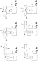
- FIGS. 4 a - c show the sequence of a bistable tumbler which is completely controlled by the electric drive 6.
- the actuator 2 at its front end as an engagement element on an inclined surface 2a. This engagement element is not needed in the bistable tumbler.
- FIG. 4a shows the initial state when the actuator 2 is not yet in the area of the locking device 1.
- the locking element 4 is retracted by means of the electric drive 6 in its release position, so that the locking element can be completely retracted into the housing 3 of the locking device 1.
- the actuator 2 can now be introduced by pivoting or moving the guard in the area of the locking device 1, which is the case when the guard is in its closed position and the actuator 2 is locked in the safety switch. This is in FIG. 4b shown.
- the actuator 2 can be extended by means of the electric drive 6 in its blocking position so that it projects into the receptacle of the actuator 2 ( Figure 4c ), whereby the tumbler of the actuator 2 is effected.
- the tumbler can then be released again by means of the electric drive 6, the tumbler element 4 is transferred to the release position.
- FIGS. 5a-5c show the procedure for the catch function.
- the actuator 2 is retracted into the region of the locking device 1, the actuator 2 is guided with the inclined surface 2a against the locking element 4 ( FIG. 5b ).
- the locking element 4 can move downwards, that is, the mechanical force exerted by the actuator 2 on the inclined surface 2a, the locking element 4 is decoupled from the electric drive 6 and against the spring force of the spring 18 down to the release position pressed.
- the locking element 4 is transferred by means of the electric drive 6 in the release position.
Landscapes
- Physics & Mathematics (AREA)
- Engineering & Computer Science (AREA)
- Electromagnetism (AREA)
- Health & Medical Sciences (AREA)
- Toxicology (AREA)
- Mechanical Engineering (AREA)
- Artificial Intelligence (AREA)
- Computer Vision & Pattern Recognition (AREA)
- General Physics & Mathematics (AREA)
- Theoretical Computer Science (AREA)
- General Health & Medical Sciences (AREA)
- Business, Economics & Management (AREA)
- Emergency Management (AREA)
- Lock And Its Accessories (AREA)
- Power-Operated Mechanisms For Wings (AREA)
Abstract
Description
- Die Erfindung betrifft eine Zuhaltevorrichtung gemäß dem Oberbegriff des Anspruchs 1.
- Im Bereich der Sicherheitstechnik werden Sicherheitsschalter bekanntlicherma-ßen zur Sicherung von Zugängen von Gefahrenbereichen eingesetzt. Beispielsweise kann mit einem Sicherheitsschalter eine Verriegelung einer Schutztür als Zugang zu einem Gefahrenbereich abgesichert werden. Der Betrieb einer gefahrbringenden Anlage innerhalb des Gefahrenbereichs wird von einer Sicherheitssteuerung nur dann freigegeben, wenn mit dem Sicherheitsschalter die Schutztür verriegelt ist. Dem Sicherheitsschalter ist hierbei ein Betätiger zugeordnet. Dabei kann typischerweise der Betätiger an der Schutztür angeordnet sein, während der Sicherheitsschalter an einem die Türöffnung begrenzenden Rahmen angeordnet ist.
- Zur Verriegelung der Schutztür wird, wenn sich die Schutztür in ihrer Schließstellung befindet, der Betätiger in Eingriff mit dem Sicherheitsschalter gebracht, indem beispielsweise der Betätiger in eine Aussparung eingefahren wird. Diese Verriegelung wird dadurch kontrolliert, dass mit einem RFID-Lesegerät im Sicherheitsschalter ein Transponder im Betätiger erkannt wird.
- Zusätzlich zu dieser Verriegelung kann eine Zuhaltung der Schutztür vorgesehen sein. Eine derartige Zuhaltung ist beispielsweise aus der
WO 2016/058718 A1 bekannt. Bei dieser Zuhaltung ist ein Zuhaltebolzen vorgesehen, der mittels eines Elektromotors mit einem Planetengetriebe betätigt wird. Mit dem elektrischen Antrieb kann der Zuhaltebolzen in eine Sperrstellung verfahren werden, in der der Betätiger mit dem Zuhaltebolzen zugehalten wird. - Der Erfindung liegt die Aufgabe zugrunde, eine Zuhaltevorrichtung der eingangs genannten Art bereitzustellen, welche eine hohe Funktionalität aufweist.
- Zur Lösung dieser Aufgabe sind die Merkmale des Anspruchs 1 vorgesehen. Vorteilhafte Ausführungsformen und zweckmäßige Weiterbildungen der Erfindung sind in den abhängigen Ansprüchen beschrieben.
- Die Erfindung betrifft ein mittels eines elektrischen Antriebs betätigbares Zuhalteelement. Mittels des elektrischen Antriebs ist das Zuhalteelement derart in eine Sperrstellung einbringbar, dass ein Betätiger eines Sicherheitsschalters mit diesem zugehalten ist. Das Zuhalteelement ist mit dem elektrischen Antrieb über eine Kupplung so verbunden, dass eine Drehbewegung des elektrischen Antriebs in eine reine Translationsbewegung des Zuhalteelements umgesetzt wird.
- Mit der erfindungsgemäßen Zuhaltevorrichtung wird eine sichere und zuverlässige Zuhaltung des Betätigers eines Sicherheitsschalters gewährleistet. Dabei besteht ein wesentlicher Aspekt der Erfindung darin, dass mit der Kupplung und vorzugsweise einer Spindelmutter an einer vom elektrischen Antrieb angetriebenen Spindel eine Umsetzung der Drehbewegung des elektrischen Anriebs in eine reine Translationsbewegung des Zuhalteelements umgesetzt wird. Dies bedeutet, dass bei der Durchführung von Stellbewegungen des Zuhalteelements, bei welchen dieses zwischen einer Sperrstellung und einer Freigabestellung bewegt wird, der Hubbewegung keine störende Drehbewegung des Zuhalteelements überlagert ist. Weiterhin ist vorteilhaft, dass sich mit der erfindungsgemäßen Zuhaltevorrichtung ein großer Hub des Zuhalteelements und dabei auch hohe Zuhaltekräfte realisieren lassen, sodass auch für unterschiedliche Ausbildungen von Betätigern und Zuhalteelementen eine zuverläsige Zuhaltung realisiert werden kann.
- Mit der erfindungsgemäßen Zuhaltevorrichtung ist eine bistabile Zuhaltung durchführbar. Mittels des elektrischen Antriebs ist das Zuhalteelement in die Sperrstellung einführbar. In dieser greift das Zuhalteelement in eine Aufnahme des Betätigers wodurch die Zuhaltung bewirkt ist. Mittels des elektrischen Antriebs kann das Zuhalteelement wieder aus der Sperrstellung ausgefahren werden.
- Bei dieser bistabilen Zuhaltung erfolgt die Bewegungssteuerung des Zuhalteelements komplett über den elektrischen Antrieb. Um den Betätiger mit dem Zuhalteelement zuhalten zu können, wird mittels des elektrischen Antriebs das Zuhalteelement vorab in seine Freigabestellung verfahren, sodass der Betätiger mit seiner Aufnahme ungehindert in den Bereich des Zuhalteelements eingebracht werden kann. Dann wird mittels des elektrischen Antriebs das Zuhalteelement in die Sperrstellung verfahren, wodurch die Zuhaltung realisiert ist.
- Die Funktionalität der erfindungsgemäßen Zuhaltevorrichtung ist dadurch noch erweitert, dass diese Entkopplungsmittel aufweist, mittels derer das Zuhalteelement vom elektrischen Antrieb entkoppelt gegen eine Federkraft aus der Sperrstellung heraus bewegbar ist.
- Damit wird eine mechanische Entriegelung der Zuhaltevorrichtung ermöglicht, was für eine Fluchtentriegelung derart genutzt werden kann, dass dann, wenn mit der Zuhaltevorrichtung zum Beispiel eine Schutztür zugehalten wird, die den Zugang zu einem Gefahrenbereich versperrt, eine Person, die sich im Gefahrenbereich aufhält, die Schutztür manuell entriegeln kann um sich aus dem Gefahrenbereich entfernen zu können. Generell kann die mechanische Entriegelung auch von der Außenseite der Schutztür, also von einer Person außerhalb des Gefahrenbereichs betätigt werden um eine Hilfsentriegelung bei einem Einsichtbereich der jeweiligen Sicherheitseinrichtung oder eine Notentsperrung der Schutztür durchzuführen.
- Gemäß einer besonders vorteilhaften Ausgestaltung der Erfindung werden die Entkopplungsmittel zur Realisierung einer Fangfunktion genutzt.
- Hierbei ist die Fangfunktion dadurch realisiert, dass mittels eines Eingriffselements des Betätigers das Zuhalteelement mechanisch und entkoppelt vom elektrischen Antrieb aus einer Sperrstellung herausbewegt ist. Wenn die Aufnahme des Betätigers im Bereich des Zuhalteelements liegt, ist dieses durch die Federkraft in die Sperrstellung zurückbewegt und greift in die Aufnahme des Betätigers.
- Diese Fangfunktion stellt eine Alternative zur bistabilen Zuhaltung dar. Im Gegensatz zur bistabilen Zuhaltung wird bei der Fangfunktion die Bewegung des Zuhalteelements nicht komplett vom elektrischen Antrieb gesteuert. Vielmehr werden die Entkopplungsmittel für eine mechanische Entkopplung mitgenutzt.
- Besonders vorteilhaft ist die Zuhaltevorrichtung wahlweise mit einer bistabilen Zuhaltung oder einer Fangfunktion betreibbar.
- Dabei ist die Funktionalität der bistabilen Zuhaltung oder der Fangfunktion durch eine Softwareversion der Zuhaltevorrichtung definiert oder durch einen Programmierbefehl vorgebbar.
- Damit wird die Funktionalität der erfindungsgemäßen Zuhaltevorrichtung erheblich erhöht.
- Gemäß einer vorteilhaften Ausgestaltung der Erfindung weist die Kupplung einen Querstift und einen quer zu diesem verlaufenden Zylinderstift auf, wobei der Querstift in einer Längsführung geführt ist und wobei der Zylinderstift den Querstift sichert.
- Die so ausgebildete Kupplung weist einen sehr einfachen Aufbau mit wenigen Teilen auf.
- Besonders vorteilhaft wird dabei mit der Kupplung zwischen dem Zuhalteelement und dem elektrischen Antrieb in axialer Richtung eine drehsteife und spielfreie Kopplung bewirkt. In lateraler Richtung ist ein Toleranzausgleich dieser Einheiten bewirkt.
- Hierzu verlaufen die Längsachsen des Querstifts und des Zylinderstifts quer zur Längsachse des Zuhalteelements, wobei der Querstift mit Spiel in einer Ausnehmung des Zuhalteelements gelagert ist und wobei der Zylinderstift mit Spiel in einer Ausnehmung des Querstifts gelagert ist.
- Durch die spielfreie und drehsteife Kopplung zwischen elektrischem Antrieb und Zuhalteelement wird eine exakte und reproduzierbare Stellbewegung des Zuhalteelements erzielt. Dieser Vorteil wird kombiniert mit dem weiteren Vorteil eines lateralen Toleranzausgleichs, der mit der Kupplung bewirkt wird. Dadurch ist die erfindungsgemäße Zuhaltung unempfindlich gegen unvermeidliche Bauteiltoleranzen, wodurch die Funktionssicherheit der Zuhaltevorrichtung erhöht wird.
- Gemäß einer zweckmäßigen konstruktiven Ausgestaltung weist der elektrische Antrieb einen Elektromotor mit einem Planetengetriebe auf. Abtriebsseitig ist am elektrischen Antrieb eine Spindel vorgesehen, die durch die Drehbewegung des elektrischen Antriebs eine Vorschubbewegung ausführt, die auf einen mittels einer Spindelmutter an die Spindel angekoppelten Mitnehmer umgesetzt ist, welcher über die Kupplung mit dem Zuhalteelement gekoppelt ist.
- Dabei ist der Mitnehmer mittels des Zylinderstifts mit der Kupplung verbunden und damit vorschubsicher gelagert.
- Die so ausgebildete Zuhaltevorrichtung weist einen kompakten, robusten Aufbau auf.
- Hierbei ist vorteilhaft, dass der Mitnehmer hohlzylindrisch ausgebildet ist, wobei der Innenraum des Mitnehmers eine Entkopplungsstrecke als Bestandteil der Entkopplungsmittel ausbildet, wobei die Spindel entlang der Entkopplungsstrecke führbar ist.
- Zudem ist eine die Federkraft erzeugende Feder zwischen dem Mitnehmer und dem Entkopplungsmittel gelagert.
- Damit wird mit geringem konstruktivem Aufwand eine mechanische Entkopplung der Zuhaltung ermöglicht.
- Gemäß einer vorteilhaften Ausführungsform ist innerhalb des Zuhalteelements ein Kabel geführt, wobei an dem Zuhalteelement ist eine Kabelumlenkung angeordnet ist, mittels derer das Kabel entlang einer Bahnkurve zwangsgeführt ist.
- Dabei ist das Kabel an ein im Zuhalteelement integriertes Sensormittel zur Kontrolle der Zuhaltung angeschlossen.
- Weiterhin ist das an der Kabelumlenkung ausmündende Kabel seitlich neben den Komponenten der Zuhaltevorrichtung geführt.
- Mit der Kabelumlenkung wird ein Abknicken oder sonstiges Beschädigen bei dem Hinausführen des Kabels aus dem Bereich des Zuhalteelements auf einfache Weise sicher verhindert. Da das an dem Zuhalteelement herausgeführte Kabel in Abstand neben den weiteren Komponenten der Zuhaltevorrichtung verläuft, wird auf einfache Weise verhindert, dass das Kabel bei einer Bewegung des Zuhalteelements in Eingriff mit diesen Komponenten kommt oder abgeknickt wird.
- Weiter vorteilhaft ist das Zuhalteelement in eine einer Freigabestellung entsprechenden unteren Endlage einbringbar, welche mittels einer Sensorik kontrollierbar ist.
- Dadurch wird eine sensorgesteuerte Zuhaltung ermöglicht, wobei das Zuhalteelement durch die Sensorik kontrolliert zwischen den die Sperrstellung und die Freigabestellung definierenden Endlagen bewegt wird.
- Insbesondere ist hierbei vorteilhaft, dass das Zuhalteelement in eine einer Freigabestellung entsprechenden unteren Endlage einbringbar ist, welche mittels einer Sensorik kontrollierbar ist. Dadurch ist die untere Position der Spindelmutter bestimmt. Ausgehend hiervon sind die weiteren Positionen der Spindelmutter mittels eines Drehgebers des elektrischen Antriebs bestimmt.
- Die Erfindung wird im Folgenden anhand der Zeichnungen erläutert. Es zeigen:
- Figur 1
- Schematische Darstellung eines Ausführungsbeispiels der erfindungsgemäßen Zuhaltevorrichtung .
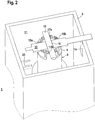
- Figur 2
- Detaildarstellung der Zuhaltevorrichtung gemäß
Figur 1 mit deren Kupplung. - Figur 3
- Detaildarstellung der Zuhaltevorrichtung gemäß
Figur 1 mit deren Zuhalteelement und einer Kabelumlenkung. - Figur 4 a- c
- Ablaufdiagramm für eine bistabile Zuhaltung mit der Zuhaltevorrichtung gemäß
Figur 1 . - Figur 5 a- c
- Ablaufdiagramm für eine Fangfunktion mit der Zuhaltevorrichtung gemäß
Figur 1 . -
Figur 1 zeigt ein Ausführungsbeispiel der erfindungsgemäßen Zuhaltevorrichtung 1. Die Zuhaltevorrichtung 1 dient zur Zuhaltung eines Betätigers 2, der Bestandteil einer Sicherheitseinrichtung mit einem nicht dargestellten Sicherheitsschalter ist. - Mit dieser Sicherheitseinrichtung erfolgt beispielsweise die Sicherung einer Schutztür als Zugang zu einem Gefahrenbereich. Der Betätiger 2 kann an der Schutztür angeordnet sein, der Sicherheitsschalter kann an einen die Türöffnung, die mit der Schutztür verschlossen wird, begrenzenden Rahmen angeordnet werden.
- Typischerweise wird die Schließstellung einer Schutztür dadurch kontrolliert, dass ein RFID Lesegerät im Sicherheitsschalter das codierte Signal eines Transponders im Betätiger liest.
- Zusätzlich zu dieser Verriegelung erfolgt eine Zuhaltung des Betätigers 2 mit der in
Figur 1 dargestellten Zuhaltevorrichtung 1. - Die Zuhaltevorrichtung 1 weist zur Aufnahme deren einzelnen Komponenten ein Gehäuse 3 auf. Zur Durchführung der Zuhaltung kann ein Zuhalteelement 4, das im vorliegenden Fall von einem Zuhaltebolzen gebildet ist, über eine Öffnung an der Oberseite des Gehäuses 3 ausgefahren werden und in eine Ausnehmung 5 an der Unterseite des Betätigers 2 eingefahren werden.
- Im unteren Bereich des Gehäuses 3 der Zuhaltevorrichtung 1 ist ein elektrischer Antrieb 6 gelagert, der einen Elektromotor mit einem Planetengetriebe aufweist. Die aktuelle Drehposition des Elektromotors wird mit einem Drehgeber 7 erfasst.
- Mit dem elektrischen Antrieb 6 wird eine Spindel 8 angetrieben. Das vordere Ende der Spindel 8 ist mit einem Mitnehmer 9 verbunden. Der Mitnehmer 9 ist hohlzylindrisch ausgebildet. Das vordere Ende der Spindel 8 ragt über die Unterseite des Mitnehmers 9 in dessen Innenraum und ist dort mittels einer Spindelmutter 10 gelagert.
- Das Zuhalteelement 4 ist mittels einer Kupplung 11 an das obere Ende des Mitnehmers 9 gekoppelt.
- Eine Drehbewegung der vom elektrischen Antrieb 6 angetriebenen Spindel 8 wird durch die Kupplung 11 und die Spindelmutter 10 in eine reine Translationsbewegung des Zuhalteelements 4 umgesetzt.
- Diese Kupplung 11 weist einen Querstift 12 und einen Zylinderstift 13 auf, deren Längsachsen senkrecht zueinander orientiert sind und jeweils senkrecht zur Längsachse des Mitnehmers 9 und des hohlzylindrischen Zuhalteelements 4 verlaufen.
- Die Längsachsen der Spindel 8, des Mitnehmers 9 und des Zuhalteelements 4 verlaufen entlang der Symmetrieachsen des Gehäuses 3.
- Der Querstift 12 ist in einer Längsführung 14 in Form eines Langlochs im Gehäuse 3 geführt. Die Längsachse des Langlochs verläuft in Längsrichtung des Gehäuses 3.
- Wie die
Figuren 2 und3 zeigen, liegt der Querstift 12 mit Spiel in Ausnehmungen 15a, 15b der Wand des Zuhalteelements 4. Der Zylinderstift 13 liegt mit Spiel in einer Ausnehmung 16 des Querstifts 12 und weiterhin in Ausnehmungen 17a, 17b in der Wand des Mitnehmers 9, wodurch der Querstift 12 gesichert ist. Durch die so ausgebildete Kupplung 11 erfolgt in axialer Richtung eine drehsteife und spielfreie Kopplung des Zuhalteelements 4 an die Spindel 8 und damit an den elektrischen Antrieb 6, sodass mittels des elektrischen Antriebs 6 exakte Hubbewegungen des Zuhalteelements 4 durchgeführt werden können. Durch die Führung des Querstifts 12 in der Längsführung 14 ist gewährleistet, dass die Drehbewegung des elektrischen Antriebs 6 in eine reine Translationsbewegung des Mitnehmers 9 und damit des Zuhalteelements 4 umgesetzt wird. Durch die Lagerung des Querstifts 12 und des Zylinderstifts 13 mit Spiel in der senkrecht zur Längsachse des Zuhalteelements 4 orientierten Ebene wird ein lateraler Toleranzausgleich bewirkt, das heißt Bauteiltoleranzen werden dadurch berücksichtigt, sodass diese die Führung des Zuhalteelements 4 nicht beeinträchtigen. - Wie aus
Figur 1 weiter ersichtlich, ist zwischen der Unterseite des Mitnehmers 9 und der Oberseite des elektrischen Antriebs 6 eine Feder 18 angeordnet, mit der eine in axialer Richtung verlaufende Federkraft generiert wird. - Die
Figuren 1 und3 zeigen das Zuhalteelement 4 in seiner Sperrstellung, in welcher dieses über die Oberseite des Gehäuses 3 hinaus ausgefahren ist. Die hierfür erforderliche Stellbewegung wird mit dem elektrischen Antrieb 6 bewirkt. Wie dieFiguren 1 und3 weiter zeigen, liegt dabei das obere Ende der Spindel 8 mit der Spindelmutter 10 im unteren Bereich des Innenraums des hohlzylindrischen Mitnehmers 9. Dieser Innenraum bildet eine Entkopplungsstrecke und damit ein Entkopplungsmittel für das Zuhalteelement 4. Mittels der Entkopplungsstrecke wird eine mechanische Entriegelung des Zuhalteelements 4, entkoppelt vom elektrischen Antrieb 6, ermöglicht. Das Zuhalteelement 4 kann nämlich aus seiner Sperrstellung in seine Freigabestellung, in welcher das Zuhalteelement 4 komplett in das Gehäuse 3 eingefahren ist, rein mechanisch und entkoppelt vom elektrischen Antrieb 6 angebracht werden, da sich bei Ausüben einer Druckkraft von oben auf das Zuhalteelement 4 die Spindelmutter 10 entlang der Entkopplungsstrecke bewegen kann. Damit wird das Zuhalteelement 4 unabhängig vom elektrischen Antrieb 6 und gegen die Federkraft der Feder 18 von der Sperrstellung in die Freigabestellung überführt. Dies kann für eine Fluchtentriegelung der Zuhaltevorrichtung 1 genutzt werden. - Wie
Figur 1 zeigt, befindet sich im oberen Bereich des Innenraums des hohlzylindrischen Zuhalteelements 4 ein Sensormittel 19. Ein hierzu korrespondierendes Sensormittel 20 befindet sich im Betätiger 2. Wenn zur Zuhaltung des Betätigers 2 das Zuhalteelement 4 in die Ausnehmung 5 des Betätigers 2 eingefahren ist, generieren die Sensormittel 19, 20 ein entsprechendes Signal. Somit wird mit diesen Sensormitteln 19, 20 die Zuhaltung kontrolliert. Die Sensormittel 19, 20 können beispielsweise von einem Näherungsschalter oder einem RFID-System gebildet sein. - Das Sensormittel 19 ist über ein Kabel 21 an eine Elektronik am elektrischen Antrieb 6 angeschlossen. Wie insbesondere
Figur 3 zeigt, verläuft das Kabel 21 vom Sensormittel 19 ausgehend im Innenraum des Zuhalteelements 4 in vertikaler Richtung. Dann wird das Kabel 21 in einer Kabelumlenkung 22 geführt. Die Kabelumlenkung 22 bildet eine Zwangsführung für das Kabel 21 derart, dass dieses zweimal um 90° abgelenkt wird. Wesentlich hierbei ist, dass das Kabel 21 in der Kabelumlenkung 22 in relativ großen Krümmungsradien umgelenkt wird und dabei spielarm zwangsgeführt ist, sodass ein Abknicken oder eine sonstige Beschädigung des Kabels 21 vermieden wird. Das an der Kabelumlenkung 22 austretende Kabel 21 verläuft dann in vertikaler Richtung zur Elektronik und ist dort angeschlossen. Wesentlich hierbei ist, dass das Kabel 21 in Abstand zu den Komponenten der Zuhaltevorrichtung 1 verläuft, sodass auch bei einer Bewegung des Zuhalteelements 4 ein Abknicken oder Einklemmen des Kabels 21 vermieden wird. - Das Zuhalteelement 4 kann mittels des elektrischen Antriebs 6 zwischen der Sperrstellung und der Freigabestellung verfahren werden, wobei diese durch nicht dargestellte Endanschläge vorgegeben sein können. Die Stellbewegungen des Zuhalteelements 4 erfolgen dabei sensorgesteuert. In der Zuhaltevorrichtung 1 ist hierzu vorteilhaft eine geeignete Sensorik vorgesehen, die im einfachsten Fall von einem einzelnen Sensorelement 23 gebildet sein kann. Mit dem Sensorelement 23 wird die untere Endlage des Zuhalteelements 4 erfasst. Wird die Spindelmutter 10 in ihre untere Endlage verfahren, wird diese mit dem Sensorelement 23 indirekt über das Erfassen der unteren Endlage des Zuhalteelements 4 bestimmt. Diese untere Endlage dient als Referenzposition. Davon ausgehend werden mit dem Drehgeber 7 des elektrischen Antriebs 6 die Relativpositionen der Spindelmutter 10 relativ zur Referenzposition erfasst. Damit wird in der Zuhaltevorrichtung 1 nur ein einziges Sensorelement 23 benötigt.
- Mit der Zuhaltevorrichtung 1 gemäß
Figur 1 kann einerseits eine bistabile Zuhaltung als auch eine Fangfunktion zur Durchführung einer Zuhaltung realisiert werden. Die Zuhaltevorrichtung 1 kann wahlweise mit einer bistabilen Zuhaltung oder einer Fangfunktion betrieben werden. Die Auswahl kann herstellerseitig durch eine geeignete Softwarevariante realisiert werden. Alternativ kann die Auswahl durch Eingabe eines Programmierbefehls einer autorisierten Person in die Steuerung der Zuhaltevorrichtung 1 erfolgen. - Die
Figuren 4 a - c zeigen den Ablauf einer bistabilen Zuhaltung die komplett über den elektrischen Antrieb 6 gesteuert wird. - Wie aus
Figur 1 und auch aus denFiguren 4 a - c ersichtlich, weist der Betätiger 2 an seinem vorderen Ende als Eingriffselement eine Schrägfläche 2a auf. Dieses Eingriffselement wird bei der bistabilen Zuhaltung nicht benötigt. -
Figur 4a zeigt den Ausgangszustand, wenn sich der Betätiger 2 noch nicht im Bereich der Zuhaltevorrichtung 1 befindet. Das Zuhalteelement 4 ist mittels des elektrischen Antriebs 6 in seine Freigabestellung eingefahren, sodass das Zuhalteelement komplett in das Gehäuse 3 der Zuhaltevorrichtung 1 eingefahren werden kann. Der Betätiger 2 kann nun durch Schwenken oder Verschieben der Schutztür in den Bereich der Zuhaltevorrichtung 1 eingebracht werden, was der Fall ist, wenn die Schutztür in ihrer Schließstellung ist und der Betätiger 2 im Sicherheitsschalter verriegelt ist. Dies ist inFigur 4b dargestellt. - Nun kann der Betätiger 2 mittels des elektrischen Antriebs 6 in seine Sperrstellung ausgefahren werden, sodass er in die Aufnahme des Betätigers 2 ragt (
Figur 4c ), wodurch die Zuhaltung des Betätigers 2 bewirkt ist. - Die Zuhaltung kann dann dadurch wieder gelöst werden, dass mittels des elektrischen Antriebs 6 das Zuhalteelement 4 in die Freigabestellung überführt wird.
- Die
Figuren 5a - 5c zeigen den Ablauf bei der Fangfunktion. - Der Ausgangszustand (
Figur 5a ), bei welchem der Betätiger 2 noch nicht im Bereich der Zuhaltevorrichtung 1 ist, ist nun derart, dass das Zuhalteelement 4 mittels des elektrischen Antriebs 6 bereits in der Sperrstellung verfahren ist. - Wenn nun der Betätiger 2 in den Bereich der Zuhaltevorrichtung 1 eingefahren wird, wird der Betätiger 2 mit der Schrägfläche 2a gegen das Zuhalteelement 4 geführt (
Figur 5b ). Durch die Entkopplungsmittel der Zuhaltevorrichtung 1 kann das Zuhalteelement 4 nach unten ausweichen, das heißt durch die von dem Betätiger 2 über die Schrägfläche 2a ausgewirkte mechanische Kraft wird das Zuhalteelement 4 vom elektrischen Antrieb 6 entkoppelt und gegen die Federkraft der Feder 18 nach unten in die Freigabestellung gedrückt. - Befindet sich der Betätiger 2 in seiner Verriegelungsposition, liegt dessen Ausnehmung 5 dicht oberhalb des Zuhalteelements 4. Durch die Federkraft der Feder 18 wird dann das Zuhalteelement 4 in seine Sperrstellung überführt, in der das Zuhalteelement in die Ausnehmung 5 greift (
Figur 5c ), das heißt die Zuhaltung ist entkoppelt vom elektrischen Antrieb 6. - Zur Lösung der Zuhaltung wird dann das Zuhalteelement 4 mittels des elektrischen Antriebs 6 in die Freigabestellung überführt.
Euchner GmbH + Co. KG
70771 Leinfelden-Echterdingen, DE -
- (1)
- Zuhaltevorrichtung
- (2)
- Betätiger
- (2a)
- Schrägfläche
- (3)
- Gehäuse
- (4)
- Zuhalteelement
- (5)
- Ausnehmung
- (6)
- elektrischer Antrieb
- (7)
- Drehgeber
- (8)
- Spindel
- (9)
- Mitnehmer
- (10)
- Spindelmutter
- (11)
- Kupplung
- (12)
- Querstift
- (13)
- Zylinderstift
- (14)
- Längsführung
- (15a, 15b)
- Ausnehmungen
- (16)
- Ausnehmung
- (17a, 17b)
- Ausnehmungen
- (18)
- Feder
- (19)
- Sensormittel
- (20)
- Sensormittel
- (21)
- Kabel
- (22)
- Kabelumlenkung
- (23)
- Sensorelement
Claims (17)
- Zuhaltevorrichtung (1) mit einem mittels eines elektrischen Antriebs (6) betätigbaren Zuhalteelement (4), wobei mittels des elektrischen Antriebs (6) das Zuhalteelement (4) in eine Sperrstellung derart einbringbar ist, dass ein Betätiger (2) eines Sicherheitsschalters mit diesem zugehalten ist, dadurch gekennzeichnet, dass das Zuhalteelement (4) mit dem elektrischen Antrieb (6) über eine Kupplung (11) so verbunden ist, dass eine Drehbewegung des elektrischen Antriebs (6) in eine reine Translationsbewegung des Zuhalteelements (4) umgesetzt ist.
- Zuhaltevorrichtung (1) nach Anspruch 1, dadurch gekennzeichnet, dass mit dieser eine bistabile Zuhaltung durchführbar ist, gemäß derer mittels des elektrischen Antriebs (6) das Zuhalteelement (4) in die Sperrstellung einfahrbar ist, wobei in dieser das Zuhalteelement (4) in eine Aufnahme des Betätigers (2) greift, wodurch dessen Zuhaltung bewirkt ist, und wobei mittels des elektrischen Antriebs (6) das Zuhalteelement (4) aus der Sperrstellung ausfahrbar ist.
- Zuhaltevorrichtung (1) nach einem der Ansprüche 1 oder 2, dadurch gekennzeichnet, dass diese Entkopplungsmittel aufweist, mittels derer das Zuhalteelement (4) vom elektrischen Antrieb (6) entkoppelt gegen eine Federkraft aus der Sperrstellung herausbewegbar ist.
- Zuhaltevorrichtung (1) nach Anspruch 3, dadurch gekennzeichnet, dass mittels der Entkopplungsmittel eine Fangfunktion für den Betätiger (2) realisierbar ist.
- Zuhaltevorrichtung (1) nach Anspruch 4, dadurch gekennzeichnet, dass die Fangfunktion dadurch realisiert ist, dass mittels eines Engriffselements des Betätigers (2) das Zuhalteelement (4) mechanisch entkoppelt vom elektrischen Antrieb (6) aus einer Sperrstellung herausbewegt ist, und dass dann, wenn die Aufnahme des Betätigers (2) im Bereich des Zuhalteelements (4) liegt, dieses durch die Federkraft in die Sperrstellung zurückbewegt ist und in die Aufnahme des Betätigers (2) greift.
- Zuhaltevorrichtung (1) nach einem der Ansprüche 4 oder 5, dadurch gekennzeichnet, dass diese wahlweise mit einer bistabilen Zuhaltung oder einer Fangfunktion betreibbar ist.
- Zuhaltevorrichtung (1) nach Anspruch 6, dadurch gekennzeichnet, dass die Funktionalität der bistabilen Zuhaltung oder der Fangfunktion durch eine Softwareversion der Zuhaltevorrichtung (1) definiert ist oder durch einen Programmierbefehl vorgebbar ist.
- Zuhaltevorrichtung (1) nach einem der Ansprüche 1 - 7, dadurch gekennzeichnet, dass die Kupplung (11) einen Querstift (12) und einen quer zu diesem verlaufenden Zylinderstift (13) aufweist, wobei der Querstift (12) in einer Längsführung (14) geführt ist, und wobei der Zylinderstift (13) den Querstift (12) sichert.
- Zuhaltevorrichtung (1) nach einem der Ansprüche 1 - 8, dadurch gekennzeichnet, dass mit der Kupplung (11) zwischen dem Zuhalteelement (4) und dem elektrischen Antrieb (6) in axialer Richtung eine drehsteife und spielfreie Kopplung bewirkt ist und in lateraler Richtung ein Toleranzausgleich dieser Einheiten bewirkt ist.
- Zuhaltevorrichtung (1) nach Anspruch 9, dadurch gekennzeichnet, dass die Längsachen des Querstifts (12) und des Zylinderstifts (13) quer zur Längsachse des Zuhalteelements (4) verlaufen, wobei der Querstift (12) mit Spiel in einer Aufnahme des Zuhalteelements (4) gelagert ist und wobei der Zylinderstift (13) mit Spiel in einer Aufnahme des Querstifts (12) gelagert ist.
- Zuhaltevorrichtung (1) nach einem der Ansprüche 1 -10, dadurch gekennzeichnet, dass der elektrische Antrieb (6) einen Elektromotor mit einem Planetengetriebe aufweist, wobei abtriebseitig am elektrischen Antrieb (6) eine Spindel (8) vorgesehen ist, deren Drehbewegung auf einen mittels einer Spindelmutter (10) an die Spindel (8) angekoppelten Mitnehmer (9) als Vorschubbewegung umgesetzt ist, welcher über die Kupplung (11) mit dem Zuhalteelement (4) gekoppelt ist.
- Zuhaltevorrichtung (1) nach Anspruch 11, dadurch gekennzeichnet, dass der Mitnehmer (9) mittels des Zylinderstifts (13) mit der Kupplung (11) verbunden ist und damit verdrehsicher gelagert ist.
- Zuhaltevorrichtung (1) nach einem der Ansprüche 11 oder 12, dadurch gekennzeichnet, dass der Mitnehmer (9) hohlzylinderisch ausgebildet ist, wobei der Innenraum des Mitnehmers (9) eine Entkopplungsstrecke als Bestandteil der Entkopplungsmittel ausbildet, wobei die Spindel (8) entlang der Entkopplungsstrecke führbar ist.
- Zuhaltevorrichtung (1) nach einem der Ansprüche 11 - 13, dadurch gekennzeichnet, dass eine die Federkraft erzeugende Feder (18) zwischen dem Mitnehmer (9) und dem elektrischen Antrieb (6) gelagert ist.
- Zuhaltevorrichtung (1) nach einem der Ansprüche 1 -14, dadurch gekennzeichnet, dass innerhalb des Zuhalteelements (4) ein Kabel (21) geführt ist, wobei an das Zuhalteelement (4) eine Kabelumlenkung (22) angeordnet ist, mittels derer das Kabel (21) entlang einer Bahnkurve zwangsgeführt ist.
- Zuhaltevorrichtung (1) nach Anspruch 15, dadurch gekennzeichnet, dass das an der Kabelumlenkung (22) ausmündende Kabel (21) seitlich neben den Komponenten der Zuhaltevorrichtung (1) geführt ist.
- Zuhaltevorrichtung (1) nach einem der Ansprüche 1 - 7, dadurch gekennzeichnet, dass das Zuhalteelement (4) in eine einer Freigabestellung entsprechenden unteren Endlage einbringbar ist, welche mittels einer Sensorik kontrollierbar ist, wodurch die untere Position der Spindelmutter (10) bestimmt ist, und dass ausgehend hiervon die weiteren Positionen der Spindelmutter (10) mittels eines Drehgebers (7) des elektrischen Antriebs bestimmt sind.
Priority Applications (5)
| Application Number | Priority Date | Filing Date | Title |
|---|---|---|---|
| ES17161677T ES2784375T3 (es) | 2017-03-17 | 2017-03-17 | Dispositivo de bloqueo |
| EP17161677.4A EP3375957B1 (de) | 2017-03-17 | 2017-03-17 | Zuhaltevorrichtung |
| US15/917,579 US11053710B2 (en) | 2017-03-17 | 2018-03-10 | Locking device |
| CN201810214685.8A CN108625680B (zh) | 2017-03-17 | 2018-03-15 | 封锁装置 |
| JP2018048143A JP2018159261A (ja) | 2017-03-17 | 2018-03-15 | ガードロック装置 |
Applications Claiming Priority (1)
| Application Number | Priority Date | Filing Date | Title |
|---|---|---|---|
| EP17161677.4A EP3375957B1 (de) | 2017-03-17 | 2017-03-17 | Zuhaltevorrichtung |
Publications (2)
| Publication Number | Publication Date |
|---|---|
| EP3375957A1 true EP3375957A1 (de) | 2018-09-19 |
| EP3375957B1 EP3375957B1 (de) | 2020-02-19 |
Family
ID=58387706
Family Applications (1)
| Application Number | Title | Priority Date | Filing Date |
|---|---|---|---|
| EP17161677.4A Active EP3375957B1 (de) | 2017-03-17 | 2017-03-17 | Zuhaltevorrichtung |
Country Status (5)
| Country | Link |
|---|---|
| US (1) | US11053710B2 (de) |
| EP (1) | EP3375957B1 (de) |
| JP (1) | JP2018159261A (de) |
| CN (1) | CN108625680B (de) |
| ES (1) | ES2784375T3 (de) |
Cited By (1)
| Publication number | Priority date | Publication date | Assignee | Title |
|---|---|---|---|---|
| AT526417B1 (de) * | 2022-12-21 | 2024-03-15 | Evva Sicherheitstechnologie | Kupplungssystem für ein elektromechanisches Schloss |
Families Citing this family (3)
| Publication number | Priority date | Publication date | Assignee | Title |
|---|---|---|---|---|
| JP7010755B2 (ja) | 2018-04-13 | 2022-01-26 | 株式会社キーエンス | 安全ドアスイッチ |
| CH715834A1 (de) * | 2019-02-12 | 2020-08-14 | Dormakaba Schweiz Ag | Programmierbarer Schliesszylinder. |
| US11401734B2 (en) | 2019-10-30 | 2022-08-02 | Schlage Lock Company Llc | Bolt mechanism with door position sensor |
Citations (7)
| Publication number | Priority date | Publication date | Assignee | Title |
|---|---|---|---|---|
| DE3049091A1 (de) * | 1980-12-24 | 1982-07-29 | Gold- und Silber-Scheideanstalt Oberstein Franz Reischauer, 6580 Idar-Oberstein | Elektromechanisches schloss |
| WO1987004213A1 (fr) * | 1986-01-14 | 1987-07-16 | Louis Bion | Verrou electrique motorise |
| DE9011080U1 (de) * | 1990-07-27 | 1991-01-03 | Schmid, Friedrich, Ing.(grad.), 8417 Lappersdorf | Verriegelungselement für Schlösser |
| EP2679750A1 (de) * | 2012-06-26 | 2014-01-01 | 9Design.be bvba | Verriegelungsvorrichtung mit einem Deaktivierungsmechanismus |
| WO2015028106A1 (de) * | 2013-08-30 | 2015-03-05 | Euchner Gmbh + Co. Kg | Betätiger eines sicherheitsschalters sowie sicherheitsschalter mit einem solchen betätiger |
| WO2016058718A1 (de) | 2014-10-17 | 2016-04-21 | Euchner Gmbh + Co. Kg | Vorrichtung zur gesteuerten arretierung oder freigabe eines sicherheitsrelevanten, beweglichen bauteils |
| EP3029226A1 (de) * | 2014-12-03 | 2016-06-08 | Harald Czellary | Elektro-verriegelungseinheit |
Family Cites Families (6)
| Publication number | Priority date | Publication date | Assignee | Title |
|---|---|---|---|---|
| DE4317365C2 (de) * | 1993-05-25 | 1996-12-05 | Fuss Fritz Gmbh & Co | Gesteuerte Riegelbetätigungsvorrichtung |
| DE10321802B4 (de) * | 2003-05-14 | 2012-09-13 | Dorma Gmbh + Co. Kg | Sicherungsvorrichtung für eine Tür, insbesondere Feuerschutztür oder dergleichen |
| DE102008060004B4 (de) * | 2008-11-25 | 2021-09-02 | Pilz Gmbh & Co. Kg | Sicherheitsschalter zum Erzeugen eines Anlagenfreigabesignals in Abhängigkeit von der Position einer beweglichen Schutztür |
| US8686869B2 (en) * | 2010-12-29 | 2014-04-01 | Secureall Corporation | Alignment-related operation and position sensing of electronic and other locks and other objects |
| CA2858410C (en) * | 2011-12-09 | 2018-01-02 | Sargent Manufacturing Company | Fire actuated release mechanism to separate electronic door lock from fire door |
| CN205637935U (zh) * | 2016-06-01 | 2016-10-12 | 洪晓君 | 一种通电释放型防火门电磁释放器 |
-
2017
- 2017-03-17 EP EP17161677.4A patent/EP3375957B1/de active Active
- 2017-03-17 ES ES17161677T patent/ES2784375T3/es active Active
-
2018
- 2018-03-10 US US15/917,579 patent/US11053710B2/en active Active
- 2018-03-15 JP JP2018048143A patent/JP2018159261A/ja active Pending
- 2018-03-15 CN CN201810214685.8A patent/CN108625680B/zh active Active
Patent Citations (7)
| Publication number | Priority date | Publication date | Assignee | Title |
|---|---|---|---|---|
| DE3049091A1 (de) * | 1980-12-24 | 1982-07-29 | Gold- und Silber-Scheideanstalt Oberstein Franz Reischauer, 6580 Idar-Oberstein | Elektromechanisches schloss |
| WO1987004213A1 (fr) * | 1986-01-14 | 1987-07-16 | Louis Bion | Verrou electrique motorise |
| DE9011080U1 (de) * | 1990-07-27 | 1991-01-03 | Schmid, Friedrich, Ing.(grad.), 8417 Lappersdorf | Verriegelungselement für Schlösser |
| EP2679750A1 (de) * | 2012-06-26 | 2014-01-01 | 9Design.be bvba | Verriegelungsvorrichtung mit einem Deaktivierungsmechanismus |
| WO2015028106A1 (de) * | 2013-08-30 | 2015-03-05 | Euchner Gmbh + Co. Kg | Betätiger eines sicherheitsschalters sowie sicherheitsschalter mit einem solchen betätiger |
| WO2016058718A1 (de) | 2014-10-17 | 2016-04-21 | Euchner Gmbh + Co. Kg | Vorrichtung zur gesteuerten arretierung oder freigabe eines sicherheitsrelevanten, beweglichen bauteils |
| EP3029226A1 (de) * | 2014-12-03 | 2016-06-08 | Harald Czellary | Elektro-verriegelungseinheit |
Cited By (2)
| Publication number | Priority date | Publication date | Assignee | Title |
|---|---|---|---|---|
| AT526417B1 (de) * | 2022-12-21 | 2024-03-15 | Evva Sicherheitstechnologie | Kupplungssystem für ein elektromechanisches Schloss |
| AT526417A4 (de) * | 2022-12-21 | 2024-03-15 | Evva Sicherheitstechnologie | Kupplungssystem für ein elektromechanisches Schloss |
Also Published As
| Publication number | Publication date |
|---|---|
| CN108625680A (zh) | 2018-10-09 |
| US20180266147A1 (en) | 2018-09-20 |
| US11053710B2 (en) | 2021-07-06 |
| EP3375957B1 (de) | 2020-02-19 |
| ES2784375T3 (es) | 2020-09-24 |
| JP2018159261A (ja) | 2018-10-11 |
| CN108625680B (zh) | 2021-05-07 |
Similar Documents
| Publication | Publication Date | Title |
|---|---|---|
| EP3482024B1 (de) | Griffvorrichtung mit einem flächenbündigen griff | |
| EP3164558B1 (de) | Vorrichtung zur gesteuerten arretierung oder freigabe eines sicherheitsrelevanten, beweglichen bauteils | |
| EP1512814B2 (de) | Kraftfahrzeug-Türschliesssystem und Türgriff | |
| EP3375957B1 (de) | Zuhaltevorrichtung | |
| DE102013114837A1 (de) | Aktive Kühlerhaubenverschlussvorrichtung für ein Fahrzeug | |
| EP0979914A2 (de) | Schliesseinrichtung | |
| EP3517714A1 (de) | Zuhaltung und sicherheitseinrichtung mit geringen abmessungen | |
| EP3621855B1 (de) | Verriegelungseinrichtung, insbesondere für ein kraftfahrzeug | |
| DE102008045195B4 (de) | Überdrehschutzanordnung für ein drehbares Bedienelement in einem Kraftfahrzeug | |
| DE10306605A1 (de) | Motorhaubenschloß für Kraftfahrzeuge | |
| WO2000032452A1 (de) | Schliessystem, insbesondere für kraftfahrzeuge | |
| DE10048224A1 (de) | Verriegelungseinheit für einen Teleskopausleger eines Krans | |
| EP4080102B1 (de) | Sicherheitsschalter mit zuhaltung | |
| EP3474304B1 (de) | Sicherheitsschalter | |
| DE102011006475A1 (de) | System mit Stellantrieb für ein Kraftfahrzeug | |
| EP1607289A1 (de) | Zündschloss für ein Kraftfahrzeug | |
| EP3474305A1 (de) | Sicherheitsschalter | |
| EP2910716B1 (de) | Zuhaltung | |
| EP2972644B1 (de) | Eingabeeinheit für ein druck- und drehbetätigbares bedienelement | |
| WO2021032373A1 (de) | Türinnengriffsystem für eine tür eines kraftfahrzeugs | |
| DE19805388A1 (de) | Türschloß mit einer Öffnungshilfe | |
| WO2016058717A1 (de) | Vorrichtung zum betätigen einer arretiereinrichtung | |
| DE102016207348B4 (de) | Türentriegelungsvorrichtung für eine verschwenkbare Tür oder Klappe eines Fahrzeugs, Sicherheitssystem | |
| DE102013018836A1 (de) | Mechanische Sperrvorrichtung, insbesondere für den Fahrzeugbereich | |
| EP3474303A1 (de) | Betätiger |
Legal Events
| Date | Code | Title | Description |
|---|---|---|---|
| PUAI | Public reference made under article 153(3) epc to a published international application that has entered the european phase |
Free format text: ORIGINAL CODE: 0009012 |
|
| STAA | Information on the status of an ep patent application or granted ep patent |
Free format text: STATUS: REQUEST FOR EXAMINATION WAS MADE |
|
| 17P | Request for examination filed |
Effective date: 20171023 |
|
| AK | Designated contracting states |
Kind code of ref document: A1 Designated state(s): AL AT BE BG CH CY CZ DE DK EE ES FI FR GB GR HR HU IE IS IT LI LT LU LV MC MK MT NL NO PL PT RO RS SE SI SK SM TR |
|
| AX | Request for extension of the european patent |
Extension state: BA ME |
|
| GRAP | Despatch of communication of intention to grant a patent |
Free format text: ORIGINAL CODE: EPIDOSNIGR1 |
|
| STAA | Information on the status of an ep patent application or granted ep patent |
Free format text: STATUS: GRANT OF PATENT IS INTENDED |
|
| RIC1 | Information provided on ipc code assigned before grant |
Ipc: E05B 15/02 20060101ALN20190912BHEP Ipc: E05B 47/02 20060101AFI20190912BHEP Ipc: E05B 47/00 20060101ALI20190912BHEP |
|
| RIC1 | Information provided on ipc code assigned before grant |
Ipc: E05B 47/00 20060101ALI20190917BHEP Ipc: E05B 15/02 20060101ALN20190917BHEP Ipc: E05B 47/02 20060101AFI20190917BHEP |
|
| INTG | Intention to grant announced |
Effective date: 20191015 |
|
| GRAS | Grant fee paid |
Free format text: ORIGINAL CODE: EPIDOSNIGR3 |
|
| GRAA | (expected) grant |
Free format text: ORIGINAL CODE: 0009210 |
|
| STAA | Information on the status of an ep patent application or granted ep patent |
Free format text: STATUS: THE PATENT HAS BEEN GRANTED |
|
| AK | Designated contracting states |
Kind code of ref document: B1 Designated state(s): AT CH DE ES FR IT LI |
|
| RBV | Designated contracting states (corrected) |
Designated state(s): AT CH DE ES FR IT LI |
|
| REG | Reference to a national code |
Ref country code: CH Ref legal event code: EP Ref country code: CH Ref legal event code: NV Representative=s name: ROTTMANN, ZIMMERMANN + PARTNER AG, CH |
|
| REG | Reference to a national code |
Ref country code: DE Ref legal event code: R096 Ref document number: 502017003824 Country of ref document: DE |
|
| REG | Reference to a national code |
Ref country code: AT Ref legal event code: REF Ref document number: 1235129 Country of ref document: AT Kind code of ref document: T Effective date: 20200315 |
|
| REG | Reference to a national code |
Ref country code: ES Ref legal event code: FG2A Ref document number: 2784375 Country of ref document: ES Kind code of ref document: T3 Effective date: 20200924 |
|
| REG | Reference to a national code |
Ref country code: DE Ref legal event code: R097 Ref document number: 502017003824 Country of ref document: DE |
|
| PLBE | No opposition filed within time limit |
Free format text: ORIGINAL CODE: 0009261 |
|
| STAA | Information on the status of an ep patent application or granted ep patent |
Free format text: STATUS: NO OPPOSITION FILED WITHIN TIME LIMIT |
|
| 26N | No opposition filed |
Effective date: 20201120 |
|
| PGFP | Annual fee paid to national office [announced via postgrant information from national office to epo] |
Ref country code: CH Payment date: 20220321 Year of fee payment: 6 Ref country code: AT Payment date: 20220322 Year of fee payment: 6 |
|
| REG | Reference to a national code |
Ref country code: CH Ref legal event code: PL |
|
| REG | Reference to a national code |
Ref country code: AT Ref legal event code: MM01 Ref document number: 1235129 Country of ref document: AT Kind code of ref document: T Effective date: 20230317 |
|
| PG25 | Lapsed in a contracting state [announced via postgrant information from national office to epo] |
Ref country code: LI Free format text: LAPSE BECAUSE OF NON-PAYMENT OF DUE FEES Effective date: 20230331 Ref country code: CH Free format text: LAPSE BECAUSE OF NON-PAYMENT OF DUE FEES Effective date: 20230331 Ref country code: AT Free format text: LAPSE BECAUSE OF NON-PAYMENT OF DUE FEES Effective date: 20230317 |
|
| PGFP | Annual fee paid to national office [announced via postgrant information from national office to epo] |
Ref country code: DE Payment date: 20240131 Year of fee payment: 8 |
|
| PGFP | Annual fee paid to national office [announced via postgrant information from national office to epo] |
Ref country code: IT Payment date: 20240329 Year of fee payment: 8 Ref country code: FR Payment date: 20240328 Year of fee payment: 8 |
|
| PGFP | Annual fee paid to national office [announced via postgrant information from national office to epo] |
Ref country code: ES Payment date: 20240429 Year of fee payment: 8 |