EP3372537B1 - Förderbandsystem - Google Patents
Förderbandsystem Download PDFInfo
- Publication number
- EP3372537B1 EP3372537B1 EP18159924.2A EP18159924A EP3372537B1 EP 3372537 B1 EP3372537 B1 EP 3372537B1 EP 18159924 A EP18159924 A EP 18159924A EP 3372537 B1 EP3372537 B1 EP 3372537B1
- Authority
- EP
- European Patent Office
- Prior art keywords
- conveyor belt
- belt
- standing walls
- segment
- plate
- Prior art date
- Legal status (The legal status is an assumption and is not a legal conclusion. Google has not performed a legal analysis and makes no representation as to the accuracy of the status listed.)
- Active
Links
Images
Classifications
-
- B—PERFORMING OPERATIONS; TRANSPORTING
- B65—CONVEYING; PACKING; STORING; HANDLING THIN OR FILAMENTARY MATERIAL
- B65G—TRANSPORT OR STORAGE DEVICES, e.g. CONVEYORS FOR LOADING OR TIPPING, SHOP CONVEYOR SYSTEMS OR PNEUMATIC TUBE CONVEYORS
- B65G15/00—Conveyors having endless load-conveying surfaces, i.e. belts and like continuous members, to which tractive effort is transmitted by means other than endless driving elements of similar configuration
- B65G15/28—Conveyors with a load-conveying surface formed by a single flat belt, not otherwise provided for
-
- B—PERFORMING OPERATIONS; TRANSPORTING
- B65—CONVEYING; PACKING; STORING; HANDLING THIN OR FILAMENTARY MATERIAL
- B65G—TRANSPORT OR STORAGE DEVICES, e.g. CONVEYORS FOR LOADING OR TIPPING, SHOP CONVEYOR SYSTEMS OR PNEUMATIC TUBE CONVEYORS
- B65G15/00—Conveyors having endless load-conveying surfaces, i.e. belts and like continuous members, to which tractive effort is transmitted by means other than endless driving elements of similar configuration
- B65G15/60—Arrangements for supporting or guiding belts, e.g. by fluid jets
-
- B—PERFORMING OPERATIONS; TRANSPORTING
- B65—CONVEYING; PACKING; STORING; HANDLING THIN OR FILAMENTARY MATERIAL
- B65G—TRANSPORT OR STORAGE DEVICES, e.g. CONVEYORS FOR LOADING OR TIPPING, SHOP CONVEYOR SYSTEMS OR PNEUMATIC TUBE CONVEYORS
- B65G21/00—Supporting or protective framework or housings for endless load-carriers or traction elements of belt or chain conveyors
- B65G21/08—Protective roofs or arch supports therefor
-
- B—PERFORMING OPERATIONS; TRANSPORTING
- B65—CONVEYING; PACKING; STORING; HANDLING THIN OR FILAMENTARY MATERIAL
- B65G—TRANSPORT OR STORAGE DEVICES, e.g. CONVEYORS FOR LOADING OR TIPPING, SHOP CONVEYOR SYSTEMS OR PNEUMATIC TUBE CONVEYORS
- B65G21/00—Supporting or protective framework or housings for endless load-carriers or traction elements of belt or chain conveyors
- B65G21/10—Supporting or protective framework or housings for endless load-carriers or traction elements of belt or chain conveyors movable, or having interchangeable or relatively movable parts; Devices for moving framework or parts thereof
-
- B—PERFORMING OPERATIONS; TRANSPORTING
- B65—CONVEYING; PACKING; STORING; HANDLING THIN OR FILAMENTARY MATERIAL
- B65G—TRANSPORT OR STORAGE DEVICES, e.g. CONVEYORS FOR LOADING OR TIPPING, SHOP CONVEYOR SYSTEMS OR PNEUMATIC TUBE CONVEYORS
- B65G21/00—Supporting or protective framework or housings for endless load-carriers or traction elements of belt or chain conveyors
- B65G21/20—Means incorporated in, or attached to, framework or housings for guiding load-carriers, traction elements or loads supported on moving surfaces
- B65G21/2045—Mechanical means for guiding or retaining the load on the load-carrying surface
- B65G21/2063—Mechanical means for guiding or retaining the load on the load-carrying surface comprising elements not movable in the direction of load-transport
- B65G21/2072—Laterial guidance means
- B65G21/2081—Laterial guidance means for bulk material, e.g. skirts
-
- B—PERFORMING OPERATIONS; TRANSPORTING
- B65—CONVEYING; PACKING; STORING; HANDLING THIN OR FILAMENTARY MATERIAL
- B65G—TRANSPORT OR STORAGE DEVICES, e.g. CONVEYORS FOR LOADING OR TIPPING, SHOP CONVEYOR SYSTEMS OR PNEUMATIC TUBE CONVEYORS
- B65G23/00—Driving gear for endless conveyors; Belt- or chain-tensioning arrangements
- B65G23/02—Belt- or chain-engaging elements
- B65G23/04—Drums, rollers, or wheels
-
- B—PERFORMING OPERATIONS; TRANSPORTING
- B65—CONVEYING; PACKING; STORING; HANDLING THIN OR FILAMENTARY MATERIAL
- B65G—TRANSPORT OR STORAGE DEVICES, e.g. CONVEYORS FOR LOADING OR TIPPING, SHOP CONVEYOR SYSTEMS OR PNEUMATIC TUBE CONVEYORS
- B65G39/00—Rollers, e.g. drive rollers, or arrangements thereof incorporated in roller-ways or other types of mechanical conveyors
- B65G39/10—Arrangements of rollers
- B65G39/12—Arrangements of rollers mounted on framework
-
- B—PERFORMING OPERATIONS; TRANSPORTING
- B65—CONVEYING; PACKING; STORING; HANDLING THIN OR FILAMENTARY MATERIAL
- B65G—TRANSPORT OR STORAGE DEVICES, e.g. CONVEYORS FOR LOADING OR TIPPING, SHOP CONVEYOR SYSTEMS OR PNEUMATIC TUBE CONVEYORS
- B65G45/00—Lubricating, cleaning, or clearing devices
- B65G45/10—Cleaning devices
-
- B—PERFORMING OPERATIONS; TRANSPORTING
- B65—CONVEYING; PACKING; STORING; HANDLING THIN OR FILAMENTARY MATERIAL
- B65G—TRANSPORT OR STORAGE DEVICES, e.g. CONVEYORS FOR LOADING OR TIPPING, SHOP CONVEYOR SYSTEMS OR PNEUMATIC TUBE CONVEYORS
- B65G47/00—Article or material-handling devices associated with conveyors; Methods employing such devices
- B65G47/22—Devices influencing the relative position or the attitude of articles during transit by conveyors
-
- B—PERFORMING OPERATIONS; TRANSPORTING
- B65—CONVEYING; PACKING; STORING; HANDLING THIN OR FILAMENTARY MATERIAL
- B65G—TRANSPORT OR STORAGE DEVICES, e.g. CONVEYORS FOR LOADING OR TIPPING, SHOP CONVEYOR SYSTEMS OR PNEUMATIC TUBE CONVEYORS
- B65G69/00—Auxiliary measures taken, or devices used, in connection with loading or unloading
- B65G69/18—Preventing escape of dust
- B65G69/181—Preventing escape of dust by means of sealed systems
-
- B—PERFORMING OPERATIONS; TRANSPORTING
- B65—CONVEYING; PACKING; STORING; HANDLING THIN OR FILAMENTARY MATERIAL
- B65G—TRANSPORT OR STORAGE DEVICES, e.g. CONVEYORS FOR LOADING OR TIPPING, SHOP CONVEYOR SYSTEMS OR PNEUMATIC TUBE CONVEYORS
- B65G2201/00—Indexing codes relating to handling devices, e.g. conveyors, characterised by the type of product or load being conveyed or handled
- B65G2201/04—Bulk
-
- B—PERFORMING OPERATIONS; TRANSPORTING
- B65—CONVEYING; PACKING; STORING; HANDLING THIN OR FILAMENTARY MATERIAL
- B65G—TRANSPORT OR STORAGE DEVICES, e.g. CONVEYORS FOR LOADING OR TIPPING, SHOP CONVEYOR SYSTEMS OR PNEUMATIC TUBE CONVEYORS
- B65G2812/00—Indexing codes relating to the kind or type of conveyors
- B65G2812/02—Belt or chain conveyors
- B65G2812/02128—Belt conveyors
- B65G2812/02138—Common features for belt conveyors
- B65G2812/02148—Driving means for the belts
-
- B—PERFORMING OPERATIONS; TRANSPORTING
- B65—CONVEYING; PACKING; STORING; HANDLING THIN OR FILAMENTARY MATERIAL
- B65G—TRANSPORT OR STORAGE DEVICES, e.g. CONVEYORS FOR LOADING OR TIPPING, SHOP CONVEYOR SYSTEMS OR PNEUMATIC TUBE CONVEYORS
- B65G2812/00—Indexing codes relating to the kind or type of conveyors
- B65G2812/02—Belt or chain conveyors
- B65G2812/02128—Belt conveyors
- B65G2812/02138—Common features for belt conveyors
- B65G2812/02168—Belts provided with guiding means, e.g. rollers
Definitions
- the invention relates to a conveyor belt system comprising a frame with a conveyor belt which is provided so as to be driven by at least two rollers so that the upper belt functions as transport surface and the lower belt functions as return.
- Conveyor belts are much used to move materials between a first location and a second location.
- the invention relates particularly here to conveyor belts which are adapted to transport bulk materials, also known as bulk cargo or bulk goods. These are materials which are not packed individually and loaded and transported, such as containers, pallets or boxes, but which are deposited in bulk in a loading space, processed and transported.
- the invention is more particularly optimized for the transport of bulk materials with fine particles. Examples hereof are sand, powder, glass dust. Where the word 'materials' is used in the remainder of the description, this is understood to mean bulk materials as described above.
- the materials comprise multiple particles, grains or particulate.
- a conveyor belt For the transport of materials a conveyor belt is provided with upper standing walls with a mutual spacing which at least at the position of the upper belt is smaller than the width of the conveyor belt.
- the materials are held in place between the upper standing walls and are supported by the upper belt, which then functions as transport surface for transporting the materials from the infeed of the conveyor belt to the outfeed of the conveyor belt.
- An operating zone is hereby defined on the conveyor belt between the standing walls. It is impossible, particularly when the materials comprise small particles, to hold all particles between the upper standing walls. The particles which come to lie outside the operating zone, for instance by moving under the upper standing walls, form contaminants which can adversely affect the operation of the conveyor belt.
- EP 1 123 880 and JPH 9-77227 disclose a conveyor belt system according to the preamble of claim 1.
- EP 1 123 880 describes such a conventional conveyor apparatus comprised of a length of formed trough having a generally U-shaped cross-section configuration with a substantial horizontal center section, a flexible endless bulk material-moving conveyor belt frictionally supported by the formed trough, a conventional drive roll, idle roll , belt tension roll , and drive motor combination cooperating with the endless material-moving belt and a bulk material enclosure positioned above and in spaced-apart relation to the endless belt.
- EP 2 944 587 describes a conveyor belt system which provides an improved solution to the above described problem.
- a standard conveyor belt system has a frame and the conveyor belt protrudes on either side through the walls of the frame so that the sides of the conveyor belt are situated outside the frame. Because the conveyor belt lies with its edges outside the frame, contaminants falling via the side of the conveyor belt will not come to lie inside the frame.
- the structure of the construction prevents with certainty the possibility of contaminants coming into contact with drive elements located in the frame of the conveyor belt system. This considerably reduces the chance of wear and/or blockage of the conveyor belt.
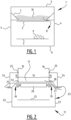
- FIG 1 shows a traditional conveyor belt 1 according to the prior art.
- Conveyor belt 1 is shown in cross-section, wherein the cross-section is through a central part of the conveyor belt.
- Figure 1 shows an upper belt 2 and a lower belt 3.
- a conveyor belt is formed as an endless belt which forms upper belt 2 and lower belt 3 and which is typically tensioned over two rollers. At least one of these two rollers is typically provided here as drive roller for driving the conveyor belt.
- the upper belt and lower belt are typically further supported and/or guided by further rollers, slots or other support elements.
- Conveyor belts can be made in different sizes with different lengths and widths and can be optimized for transport of various types of material.
- the invention relates particularly to the transport of bulk materials.
- the invention is more specifically optimized for bulk materials with small particles.
- Bulk materials are typically deposited onto the conveyor belt at a beginning of the conveyor belt.
- Conveyor belt 1 typically has for this purpose an open upper side at a beginning.
- At an end of the conveyor belt the bulk materials typically drop off the belt.
- the conveyor belt will therefore be open at the bottom so that the bulk materials can drop off the belt.
- a scraper can be provided here at the end of the conveyor belt, at the position of the roller over which the conveyor belt runs, to urge a maximum of the bulk materials to drop off the conveyor belt.
- Such a construction and the described mechanisms are known and can also be applied in the conveyor belt according to the invention.
- Figure 1 shows a cross-section of a middle part of a traditional conveyor belt 1.
- the conveyor belt has an operating zone 10.
- the operating zone is defined by upper belt 2, which functions as transport surface, and the upper standing walls 7.
- Upper standing walls 7 are placed above upper belt 2 and with a mutual spacing, at least at the position of upper belt 2, which is smaller than the width of upper belt 2.
- Upper standing walls 7 will hereby function as guide or stop for the bulk materials in order to hold the materials within operating zone 10 of the conveyor belt.
- Conveyor belt 1 further has two standing walls 4 which screen the conveyor belt from the surrounding area. Ambient influences are also excluded from the conveyor belt by standing walls 4. It will be apparent in this context that different operating elements of conveyor belt 1, for instance guide elements, drive elements and so on, are preferably screened off from the surrounding area. It can also be advantageous to keep ambient influences such as dirt, water, wind and so on away from these operating elements of conveyor belt 1.
- conveyor belt 1 is further provided with an upper wall 5 which also covers the operating zone 10 of the conveyor belt. Just as the two standing walls 4, this covering functions in two directions.
- the surrounding area is screened off from the materials on the conveyor belt. This is relevant for instance when the bulk materials have very fine particles which can be blown about and thereby foul the surrounding area.
- upper wall 5 screens the operating zone 10 from ambient influences such as wind, water, dirt etc.
- conveyor belt 1 is further provided with a lower wall 6.
- Lower wall 6 is optional and can be formed by a plate or by a floor on which conveyor belt 1 is placed.
- FIG. 2 shows a conveyor belt system 11 according to the invention.
- Conveyor belt system 11 comprises an upper belt 12 and a lower belt 13 which extend in conventional manner from a first roller to a second roller (not shown) at respectively the beginning and the end of the conveyor belt.
- Upper belt 12 and lower belt 13 form the conveyor belt, which is formed as endless belt and which can be mounted in traditional manner around two rollers.
- the conveyor belt system 11 preferably has a traditional construction. That is, drive elements and provisions for loading and unloading materials onto and from transport system 11 take a traditional form.
- Upper belt 12 has as seen in transverse direction a central zone 14 and two edge zones 15, also referred to below as edges 15.
- Central zone 14 forms the transport surface of the conveyor belt system. Edges 15 extend on either side of central zone 14.
- the separation between central zone 14 and edges 15 is preferably defined by upper standing walls 16.
- Upper standing walls 16 form guides for the materials on the transport surface for the purpose of holding the materials within an operating zone 17 of conveyor belt system 11.
- Operating zone 17 preferably extends above the central zone 14 forming the transport surface so that materials on operating zone 17 can be transported from a beginning of conveyor belt system 11 to the end of conveyor belt system 11.
- Upper standing walls 17 are intended here for the purpose of holding the materials within operating zone 17.
- Seals 18 are preferably provided between upper belt 12 and upper standing walls 16. Seals 18 increase the barrier or resistance to the materials in operating zone 17 moving to edges 15 of upper belt 12. Seals 18 can be formed in different ways, for instance by brushes, rubbers, felts or other known barrier mechanisms or sealing elements. Seals are known and not therefore discussed further.
- Conveyor belt system 11 further comprises a plate 19.
- Plate 19 extends in the transverse direction of conveyor belt system 11 from below upper belt 12 to an outer side of the frame of conveyor belt system 11.
- a plate 19 is provided on either side of upper belt 12.
- Each plate 19 has a first segment 20 and a second segment 21.
- First segment 20 is provided for the purpose of lying under upper belt 12.
- First segment 20 preferably lies at least under edges 15 of upper belt 12.
- Plates 19 hereby support upper belt 12 at the position of the edges.
- support rollers 26 extend between plates 19 in order to support central zone 14 of upper belt 12. The skilled person will appreciate that this is only one embodiment and that more ways of supporting upper belt 12, and more specifically central zone 14 of upper belt 12, can be envisaged.
- Second segment 21 of plate 19 spans a distance between the outermost edge of upper belt 12 and an outer side of the frame of conveyor belt system 11.
- the frame typically comprises lower standing walls 22.
- Lower standing walls 22 typically have a mutual spacing greater than the width of the conveyor belt so that the space below upper belt 12, preferably including lower belt 13, is encased by lower standing walls 22.
- the second segments of plates 19 extend to an outer side of lower standing walls 22.
- Upper standing walls 16, and more specifically seals 18, are preferably positioned in transverse direction of conveyor belt system 11 above first segment 20 of plate 19. This allows upper belt 12 to be clamped between plate 19, which functions as support for upper belt 12, and seal 18 which defines operating zone 17 of the conveyor belt system. This construction allows a seal to be realized which functions reliably.
- conveyor belt system 11 as shown in figure 2 has the effect that contaminants are always carried to an outer side of the frame of conveyor belt system 11. The contaminants cannot therefore accumulate on lower belt 13 as illustrated in figure 1 .
- second segment 21 of plate 19 takes a form draining in a direction away from upper belt 12.
- the main purpose of plate 19 is to divert or discharge contaminants to a location outside the frame of conveyor belt system 11.
- the path followed by contaminants is designated with arrow 23. This has also been described above as leakage 23. It will be apparent from figure 2 that contaminants cannot drop onto lower belt 13.
- the conveyor belt system 11 can be further provided with a cover 24 which extends at least partially over an upper side of plate 19 on an outer side of upper standing walls 16.
- Cover 24 can for instance be connected hingedly 25 to upper standing walls 16 so that cover 24 can be opened. Contaminants will accumulate inside cover 24 and can be removed in extremely simple manner by a service engineer.
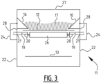
- Figure 3 shows an alternative embodiment, which is not part of the claimed invention.
- Figure 3 shows how the frame is constructed with lower standing walls 22.
- Lower standing walls 22 extend further upward to a position above upper belt 12 of the conveyor belt.
- Further upper standing walls 16 are provided above upper belt 12.
- Upper standing walls 16 extend from lower standing walls 22 to a position above upper belt 12.
- At the position of upper belt 12 upper standing walls 16 have a mutual spacing smaller than the width of upper belt 12.
- Elements 16 hereby form the upper standing walls, while walls 22 fulfil the function of the lower standing walls.
- Plate 19 is further provided under the edges of upper belt 12. Plate 19 extends to an outer side of lower standing walls 22. It will be apparent here that openings 28 are provided in lower standing walls 22 so that contaminants on the plate can move from a peripheral edge of upper belt 12 to an outer side of lower standing walls 22.
- a cover 24 can further be provided similar to cover 24 of figure 2 .
Landscapes
- Engineering & Computer Science (AREA)
- Mechanical Engineering (AREA)
- Structure Of Belt Conveyors (AREA)
Claims (12)
- Förderbandsystem (11), umfassend einen Rahmen mit einem Förderband (12, 13), das bereitgestellt ist, so dass es durch mindestens zwei Rollen angetrieben wird, so dass ein oberes Band (12) als Transportoberfläche fungiert und ein unteres Band (13) als Rücklauf fungiert, wobei der Rahmen ein oberes Segment, das sich im Wesentlichen über dem oberen Band (12) erstreckt, und ein unteres Segment aufweist, das sich im Wesentlichen unter dem oberen Band (12) erstreckt, wobei das obere Segment mindestens zwei obere stehende Wände (16) mit einem gegenseitigen Abstand aufweist, der mindestens an der Position des oberen Bandes (12) kleiner als die Breite des Förderbandes (12, 13) ist, wobei das untere Segment mindestens zwei untere stehende Wände (22) mit einem gegenseitigen Abstand aufweist, der größer als die Breite des Förderbandes ist, wobei das obere Band (12) auf beiden Seiten durch eine Platte (19) gestützt wird, die sich jeweils von unterhalb des oberen Bandes (12) zu einer Außenseite der unteren stehenden Wand (22) erstreckt, und wobei die Platte (19) ein erstes Segment (20) zum Stützen des oberen Bandes (12) aufweist, dadurch gekennzeichnet, dass die Platte (19) ein zweites Segment (21) zum Abführen von Verunreinigungen aufweist, wobei das zweite Segment (21) aus einer Querrichtung des Förderbandsystems gesehen mindestens teilweise von dem Förderband weg abführt.
- Förderbandsystem (11) nach Anspruch 1, wobei das zweite Segment mindestens teilweise durch eine abnehmbare Abdeckung (24) abgeschirmt ist.
- Förderbandsystem (11) nach einem der Ansprüche 1 bis 2, wobei die Platte (19) in zwei Teilen vorhanden ist und wobei jeder Teil sich auf beiden Seiten des oberen Bandes (12) befindet.
- Förderbandsystem (11) nach Anspruch 3, wobei zwischen den zwei Teilen der Platte (19) Führungsrollen bereitgestellt sind, wobei die Führungsrollen das obere Band (12) in einer mittleren Zone (14) davon stützen.
- Förderbandsystem (11) nach einem der vorstehenden Ansprüche, wobei die oberen stehenden Wände (16) an der Position des Förderbands mit einer Dichtung (18) bereitgestellt sind, so dass Materialien auf dem Förderband zwischen den oberen stehenden Wänden (16) eingeschlossen sind.
- Förderbandsystem (11) nach Anspruch 5, wobei Druckdifferenzmittel bereitgestellt sind, um eine Druckdifferenz über der Dichtung zu erzielen, so dass eine Leckage über die Dichtung minimal ist.
- Förderbandsystem (11) nach einem der Ansprüche 1 bis 4 und Anspruch 5 oder 6, wobei die Dichtung (18) in der Querrichtung des Förderbands an der Position des ersten Segments der Platte bereitgestellt ist.
- Förderbandsystem (11) nach einem der vorstehenden Ansprüche, wobei die unteren stehenden Wände sich bis zu einer Höhe unterhalb des unteren Bandes (13) erstrecken.
- Förderbandsystem (11) nach einem der vorstehenden Ansprüche, wobei das obere Segment ein Dachelement umfasst, das sich zwischen den zwei oberen stehenden Wänden (16) erstreckt, um die Transportoberfläche zu umschließen.
- Förderbandsystem (11) nach einem der vorstehenden Ansprüche, wobei das Förderband in der Querrichtung im Wesentlichen mittig relativ zu mindestens einem der zwei oberen stehenden Wände (16) und der zwei unteren stehenden Wände (22) und der Platte (19) gelegen ist.
- Förderbandsystem (11) nach einem der vorstehenden Ansprüche, wobei die oberen stehenden Wände (16), die Platte (19) und die unteren stehenden Wände (22) sich über eine Länge erstrecken, die im Wesentlichen gleich der Länge des oberen Bandes (12) des Förderbandes ist.
- Förderbandsystem (11) nach einem der vorstehenden Ansprüche, wobei Stützelemente unter dem unteren Band (13) bereitgestellt sind.
Applications Claiming Priority (1)
| Application Number | Priority Date | Filing Date | Title |
|---|---|---|---|
| BE2017/5136A BE1025035B1 (nl) | 2017-03-06 | 2017-03-06 | Transportbandsysteem |
Publications (2)
| Publication Number | Publication Date |
|---|---|
| EP3372537A1 EP3372537A1 (de) | 2018-09-12 |
| EP3372537B1 true EP3372537B1 (de) | 2024-09-25 |
Family
ID=58347004
Family Applications (1)
| Application Number | Title | Priority Date | Filing Date |
|---|---|---|---|
| EP18159924.2A Active EP3372537B1 (de) | 2017-03-06 | 2018-03-05 | Förderbandsystem |
Country Status (5)
| Country | Link |
|---|---|
| US (1) | US10427877B2 (de) |
| EP (1) | EP3372537B1 (de) |
| BE (1) | BE1025035B1 (de) |
| ES (1) | ES2997960T3 (de) |
| PL (1) | PL3372537T3 (de) |
Families Citing this family (7)
| Publication number | Priority date | Publication date | Assignee | Title |
|---|---|---|---|---|
| BE1027494B1 (nl) * | 2019-08-12 | 2021-03-16 | Clean Conveyor Belt BVBA | Transportband met opstaande ribben |
| CN110733860B (zh) * | 2019-11-18 | 2024-12-13 | 邵阳市清清山泉水有限责任公司 | 桶装水自动化灌装生产线清洗装置 |
| US12214309B2 (en) | 2021-04-06 | 2025-02-04 | Benetech, Inc. | Passive dust filter for an inspection hatch |
| US11919719B2 (en) | 2021-05-13 | 2024-03-05 | Benetech, Inc. | Drop and slide out idler assembly |
| JP7761338B2 (ja) * | 2021-12-10 | 2025-10-28 | 株式会社日向製錬所 | 鉱石搬送路用の架台、及び、鉱石搬送設備 |
| CN115649793A (zh) * | 2022-03-21 | 2023-01-31 | 郝燕 | 一种高效的建筑施工用砂石物料转运装置 |
| CN120440555B (zh) * | 2025-07-11 | 2025-09-19 | 兴化顶康食品科技有限公司 | 一种蔬菜加工输送装置 |
Family Cites Families (11)
| Publication number | Priority date | Publication date | Assignee | Title |
|---|---|---|---|---|
| JPS54122578A (en) * | 1978-03-14 | 1979-09-22 | Nippon Kokan Kk <Nkk> | Overhead belt conveyor |
| US4674626A (en) * | 1983-12-15 | 1987-06-23 | M. L. Eakes Co. | Leakproof endless belt conveyor |
| JPS6144409U (ja) * | 1984-08-22 | 1986-03-24 | トヨタ自動車株式会社 | 防水カバ−付スラツトコンベヤ |
| ZA939109B (en) * | 1992-11-04 | 1994-08-22 | Brelko Patents Pty Ltd | Belt conveyor skirt seal arrangement |
| US5458230A (en) * | 1994-03-16 | 1995-10-17 | Balcar; James E. | Center loading conveyor assembly |
| JPH0977227A (ja) * | 1995-09-14 | 1997-03-25 | Tsubakimoto Baruku Syst:Kk | ベルト式トラフコンベヤ |
| US6293389B1 (en) | 2000-02-08 | 2001-09-25 | William L. McLean | En masse bulk material conveyor apparatus |
| JP2004051338A (ja) * | 2002-07-23 | 2004-02-19 | Bando Chem Ind Ltd | 粉体搬送装置 |
| US6681921B1 (en) * | 2002-09-30 | 2004-01-27 | Intersystems, A Division Of Enduro Systems, Inc. | Enclosed belt conveyor assembly |
| BE1021981B1 (nl) | 2014-05-15 | 2016-02-01 | VEJOPIROX naamloze vennootschap | Gesloten transportband |
| AU2015215884B2 (en) * | 2014-10-28 | 2018-08-23 | Haze Ag Pty Ltd | Modular broadcast spreader |
-
2017
- 2017-03-06 BE BE2017/5136A patent/BE1025035B1/nl active IP Right Grant
-
2018
- 2018-03-05 PL PL18159924.2T patent/PL3372537T3/pl unknown
- 2018-03-05 ES ES18159924T patent/ES2997960T3/es active Active
- 2018-03-05 EP EP18159924.2A patent/EP3372537B1/de active Active
- 2018-03-06 US US15/913,313 patent/US10427877B2/en active Active
Also Published As
| Publication number | Publication date |
|---|---|
| PL3372537T3 (pl) | 2025-01-27 |
| US10427877B2 (en) | 2019-10-01 |
| EP3372537A1 (de) | 2018-09-12 |
| BE1025035B1 (nl) | 2018-10-10 |
| ES2997960T3 (en) | 2025-02-18 |
| US20180251306A1 (en) | 2018-09-06 |
| BE1025035A1 (nl) | 2018-10-03 |
Similar Documents
| Publication | Publication Date | Title |
|---|---|---|
| EP3372537B1 (de) | Förderbandsystem | |
| EP3778438B1 (de) | Förderband mit aufrechten rippen | |
| US4674626A (en) | Leakproof endless belt conveyor | |
| GB2403463A (en) | Seal-less slat-type reciprocating conveyor | |
| JP2005225678A (ja) | エンドレス状の搬送面を運ぶように構成されたガイド面と、該ガイド面を備えたコンベア | |
| NL8401329A (nl) | Bandtransporteur voor het verticaal of steil transporteren van stortgoed. | |
| EP0593234B1 (de) | Schwingfördereinrichtung | |
| CN110733830A (zh) | 一种输送带系统 | |
| EP4077173B1 (de) | Innenreinigungssystem für endlosbandförderer | |
| SU1719831A1 (ru) | Карусельна сушилка | |
| JP3734861B2 (ja) | ばら物運搬用パイプコンベヤにおける粉塵飛散防止装置 | |
| KR200339713Y1 (ko) | 벨트 컨베이어의 분진 비산방지장치 | |
| CN212355497U (zh) | 一种移动可逆带式输送系统 | |
| CA2435704C (en) | Sealless slat-type reciprocating conveyor | |
| KR101090871B1 (ko) | 원료 공급용 벨트 컨베이어 구동장치 | |
| JPH10338323A (ja) | 空気浮上式ベルトコンベヤ装置 | |
| KR20100107737A (ko) | 벨트컨베이어용 낙광 방지장치 | |
| JPS586835A (ja) | リクレ−マ装置 |
Legal Events
| Date | Code | Title | Description |
|---|---|---|---|
| PUAI | Public reference made under article 153(3) epc to a published international application that has entered the european phase |
Free format text: ORIGINAL CODE: 0009012 |
|
| STAA | Information on the status of an ep patent application or granted ep patent |
Free format text: STATUS: THE APPLICATION HAS BEEN PUBLISHED |
|
| AK | Designated contracting states |
Kind code of ref document: A1 Designated state(s): AL AT BE BG CH CY CZ DE DK EE ES FI FR GB GR HR HU IE IS IT LI LT LU LV MC MK MT NL NO PL PT RO RS SE SI SK SM TR |
|
| AX | Request for extension of the european patent |
Extension state: BA ME |
|
| STAA | Information on the status of an ep patent application or granted ep patent |
Free format text: STATUS: REQUEST FOR EXAMINATION WAS MADE |
|
| 17P | Request for examination filed |
Effective date: 20190312 |
|
| RBV | Designated contracting states (corrected) |
Designated state(s): AL AT BE BG CH CY CZ DE DK EE ES FI FR GB GR HR HU IE IS IT LI LT LU LV MC MK MT NL NO PL PT RO RS SE SI SK SM TR |
|
| STAA | Information on the status of an ep patent application or granted ep patent |
Free format text: STATUS: EXAMINATION IS IN PROGRESS |
|
| 17Q | First examination report despatched |
Effective date: 20210702 |
|
| GRAP | Despatch of communication of intention to grant a patent |
Free format text: ORIGINAL CODE: EPIDOSNIGR1 |
|
| STAA | Information on the status of an ep patent application or granted ep patent |
Free format text: STATUS: GRANT OF PATENT IS INTENDED |
|
| INTG | Intention to grant announced |
Effective date: 20240626 |
|
| GRAS | Grant fee paid |
Free format text: ORIGINAL CODE: EPIDOSNIGR3 |
|
| GRAA | (expected) grant |
Free format text: ORIGINAL CODE: 0009210 |
|
| STAA | Information on the status of an ep patent application or granted ep patent |
Free format text: STATUS: THE PATENT HAS BEEN GRANTED |
|
| AK | Designated contracting states |
Kind code of ref document: B1 Designated state(s): AL AT BE BG CH CY CZ DE DK EE ES FI FR GB GR HR HU IE IS IT LI LT LU LV MC MK MT NL NO PL PT RO RS SE SI SK SM TR |
|
| REG | Reference to a national code |
Ref country code: GB Ref legal event code: FG4D |
|
| REG | Reference to a national code |
Ref country code: CH Ref legal event code: EP |
|
| REG | Reference to a national code |
Ref country code: DE Ref legal event code: R096 Ref document number: 602018074654 Country of ref document: DE |
|
| REG | Reference to a national code |
Ref country code: IE Ref legal event code: FG4D |
|
| REG | Reference to a national code |
Ref country code: NL Ref legal event code: FP |
|
| REG | Reference to a national code |
Ref country code: SE Ref legal event code: TRGR |
|
| P01 | Opt-out of the competence of the unified patent court (upc) registered |
Free format text: CASE NUMBER: APP_59708/2024 Effective date: 20241105 |
|
| REG | Reference to a national code |
Ref country code: LT Ref legal event code: MG9D |
|
| PG25 | Lapsed in a contracting state [announced via postgrant information from national office to epo] |
Ref country code: NO Free format text: LAPSE BECAUSE OF FAILURE TO SUBMIT A TRANSLATION OF THE DESCRIPTION OR TO PAY THE FEE WITHIN THE PRESCRIBED TIME-LIMIT Effective date: 20241225 |
|
| PG25 | Lapsed in a contracting state [announced via postgrant information from national office to epo] |
Ref country code: GR Free format text: LAPSE BECAUSE OF FAILURE TO SUBMIT A TRANSLATION OF THE DESCRIPTION OR TO PAY THE FEE WITHIN THE PRESCRIBED TIME-LIMIT Effective date: 20241226 Ref country code: FI Free format text: LAPSE BECAUSE OF FAILURE TO SUBMIT A TRANSLATION OF THE DESCRIPTION OR TO PAY THE FEE WITHIN THE PRESCRIBED TIME-LIMIT Effective date: 20240925 |
|
| PG25 | Lapsed in a contracting state [announced via postgrant information from national office to epo] |
Ref country code: BG Free format text: LAPSE BECAUSE OF FAILURE TO SUBMIT A TRANSLATION OF THE DESCRIPTION OR TO PAY THE FEE WITHIN THE PRESCRIBED TIME-LIMIT Effective date: 20240925 |
|
| PG25 | Lapsed in a contracting state [announced via postgrant information from national office to epo] |
Ref country code: LV Free format text: LAPSE BECAUSE OF FAILURE TO SUBMIT A TRANSLATION OF THE DESCRIPTION OR TO PAY THE FEE WITHIN THE PRESCRIBED TIME-LIMIT Effective date: 20240925 |
|
| PG25 | Lapsed in a contracting state [announced via postgrant information from national office to epo] |
Ref country code: RS Free format text: LAPSE BECAUSE OF FAILURE TO SUBMIT A TRANSLATION OF THE DESCRIPTION OR TO PAY THE FEE WITHIN THE PRESCRIBED TIME-LIMIT Effective date: 20241225 |
|
| PG25 | Lapsed in a contracting state [announced via postgrant information from national office to epo] |
Ref country code: RS Free format text: LAPSE BECAUSE OF FAILURE TO SUBMIT A TRANSLATION OF THE DESCRIPTION OR TO PAY THE FEE WITHIN THE PRESCRIBED TIME-LIMIT Effective date: 20241225 Ref country code: NO Free format text: LAPSE BECAUSE OF FAILURE TO SUBMIT A TRANSLATION OF THE DESCRIPTION OR TO PAY THE FEE WITHIN THE PRESCRIBED TIME-LIMIT Effective date: 20241225 Ref country code: LV Free format text: LAPSE BECAUSE OF FAILURE TO SUBMIT A TRANSLATION OF THE DESCRIPTION OR TO PAY THE FEE WITHIN THE PRESCRIBED TIME-LIMIT Effective date: 20240925 Ref country code: GR Free format text: LAPSE BECAUSE OF FAILURE TO SUBMIT A TRANSLATION OF THE DESCRIPTION OR TO PAY THE FEE WITHIN THE PRESCRIBED TIME-LIMIT Effective date: 20241226 Ref country code: FI Free format text: LAPSE BECAUSE OF FAILURE TO SUBMIT A TRANSLATION OF THE DESCRIPTION OR TO PAY THE FEE WITHIN THE PRESCRIBED TIME-LIMIT Effective date: 20240925 Ref country code: BG Free format text: LAPSE BECAUSE OF FAILURE TO SUBMIT A TRANSLATION OF THE DESCRIPTION OR TO PAY THE FEE WITHIN THE PRESCRIBED TIME-LIMIT Effective date: 20240925 |
|
| REG | Reference to a national code |
Ref country code: AT Ref legal event code: MK05 Ref document number: 1726509 Country of ref document: AT Kind code of ref document: T Effective date: 20240925 |
|
| REG | Reference to a national code |
Ref country code: ES Ref legal event code: FG2A Ref document number: 2997960 Country of ref document: ES Kind code of ref document: T3 Effective date: 20250218 |
|
| PGFP | Annual fee paid to national office [announced via postgrant information from national office to epo] |
Ref country code: SE Payment date: 20250311 Year of fee payment: 8 |
|
| PG25 | Lapsed in a contracting state [announced via postgrant information from national office to epo] |
Ref country code: IS Free format text: LAPSE BECAUSE OF FAILURE TO SUBMIT A TRANSLATION OF THE DESCRIPTION OR TO PAY THE FEE WITHIN THE PRESCRIBED TIME-LIMIT Effective date: 20250125 Ref country code: PT Free format text: LAPSE BECAUSE OF FAILURE TO SUBMIT A TRANSLATION OF THE DESCRIPTION OR TO PAY THE FEE WITHIN THE PRESCRIBED TIME-LIMIT Effective date: 20250127 |
|
| PGFP | Annual fee paid to national office [announced via postgrant information from national office to epo] |
Ref country code: DE Payment date: 20250319 Year of fee payment: 8 |
|
| PG25 | Lapsed in a contracting state [announced via postgrant information from national office to epo] |
Ref country code: RO Free format text: LAPSE BECAUSE OF FAILURE TO SUBMIT A TRANSLATION OF THE DESCRIPTION OR TO PAY THE FEE WITHIN THE PRESCRIBED TIME-LIMIT Effective date: 20240925 Ref country code: SM Free format text: LAPSE BECAUSE OF FAILURE TO SUBMIT A TRANSLATION OF THE DESCRIPTION OR TO PAY THE FEE WITHIN THE PRESCRIBED TIME-LIMIT Effective date: 20240925 |
|
| PGFP | Annual fee paid to national office [announced via postgrant information from national office to epo] |
Ref country code: NL Payment date: 20250324 Year of fee payment: 8 |
|
| PGFP | Annual fee paid to national office [announced via postgrant information from national office to epo] |
Ref country code: IE Payment date: 20250320 Year of fee payment: 8 |
|
| PG25 | Lapsed in a contracting state [announced via postgrant information from national office to epo] |
Ref country code: EE Free format text: LAPSE BECAUSE OF FAILURE TO SUBMIT A TRANSLATION OF THE DESCRIPTION OR TO PAY THE FEE WITHIN THE PRESCRIBED TIME-LIMIT Effective date: 20240925 Ref country code: AT Free format text: LAPSE BECAUSE OF FAILURE TO SUBMIT A TRANSLATION OF THE DESCRIPTION OR TO PAY THE FEE WITHIN THE PRESCRIBED TIME-LIMIT Effective date: 20240925 |
|
| PGFP | Annual fee paid to national office [announced via postgrant information from national office to epo] |
Ref country code: BE Payment date: 20250320 Year of fee payment: 8 |
|
| PG25 | Lapsed in a contracting state [announced via postgrant information from national office to epo] |
Ref country code: CZ Free format text: LAPSE BECAUSE OF FAILURE TO SUBMIT A TRANSLATION OF THE DESCRIPTION OR TO PAY THE FEE WITHIN THE PRESCRIBED TIME-LIMIT Effective date: 20240925 |
|
| PGFP | Annual fee paid to national office [announced via postgrant information from national office to epo] |
Ref country code: FR Payment date: 20250324 Year of fee payment: 8 Ref country code: PL Payment date: 20250224 Year of fee payment: 8 |
|
| PG25 | Lapsed in a contracting state [announced via postgrant information from national office to epo] |
Ref country code: SK Free format text: LAPSE BECAUSE OF FAILURE TO SUBMIT A TRANSLATION OF THE DESCRIPTION OR TO PAY THE FEE WITHIN THE PRESCRIBED TIME-LIMIT Effective date: 20240925 |
|
| PGFP | Annual fee paid to national office [announced via postgrant information from national office to epo] |
Ref country code: GB Payment date: 20250324 Year of fee payment: 8 |
|
| PGFP | Annual fee paid to national office [announced via postgrant information from national office to epo] |
Ref country code: TR Payment date: 20250225 Year of fee payment: 8 |
|
| REG | Reference to a national code |
Ref country code: DE Ref legal event code: R097 Ref document number: 602018074654 Country of ref document: DE |
|
| PG25 | Lapsed in a contracting state [announced via postgrant information from national office to epo] |
Ref country code: DK Free format text: LAPSE BECAUSE OF FAILURE TO SUBMIT A TRANSLATION OF THE DESCRIPTION OR TO PAY THE FEE WITHIN THE PRESCRIBED TIME-LIMIT Effective date: 20240925 |
|
| PGFP | Annual fee paid to national office [announced via postgrant information from national office to epo] |
Ref country code: ES Payment date: 20250416 Year of fee payment: 8 |
|
| PGFP | Annual fee paid to national office [announced via postgrant information from national office to epo] |
Ref country code: IT Payment date: 20250331 Year of fee payment: 8 |
|
| PGFP | Annual fee paid to national office [announced via postgrant information from national office to epo] |
Ref country code: CH Payment date: 20250401 Year of fee payment: 8 |
|
| PLBE | No opposition filed within time limit |
Free format text: ORIGINAL CODE: 0009261 |
|
| STAA | Information on the status of an ep patent application or granted ep patent |
Free format text: STATUS: NO OPPOSITION FILED WITHIN TIME LIMIT |
|
| 26N | No opposition filed |
Effective date: 20250626 |
|
| PG25 | Lapsed in a contracting state [announced via postgrant information from national office to epo] |
Ref country code: MC Free format text: LAPSE BECAUSE OF FAILURE TO SUBMIT A TRANSLATION OF THE DESCRIPTION OR TO PAY THE FEE WITHIN THE PRESCRIBED TIME-LIMIT Effective date: 20240925 |
|
| PG25 | Lapsed in a contracting state [announced via postgrant information from national office to epo] |
Ref country code: LU Free format text: LAPSE BECAUSE OF NON-PAYMENT OF DUE FEES Effective date: 20250305 |
|
| PG25 | Lapsed in a contracting state [announced via postgrant information from national office to epo] |
Ref country code: HR Free format text: LAPSE BECAUSE OF FAILURE TO SUBMIT A TRANSLATION OF THE DESCRIPTION OR TO PAY THE FEE WITHIN THE PRESCRIBED TIME-LIMIT Effective date: 20240925 |