EP3372452B1 - Temperaturmanagement einer fahrerassistenzkamera über eine fahrzeugwindschutzscheibe - Google Patents
Temperaturmanagement einer fahrerassistenzkamera über eine fahrzeugwindschutzscheibe Download PDFInfo
- Publication number
- EP3372452B1 EP3372452B1 EP18160086.7A EP18160086A EP3372452B1 EP 3372452 B1 EP3372452 B1 EP 3372452B1 EP 18160086 A EP18160086 A EP 18160086A EP 3372452 B1 EP3372452 B1 EP 3372452B1
- Authority
- EP
- European Patent Office
- Prior art keywords
- bracket
- housing
- thermally conductive
- windshield
- conductive body
- Prior art date
- Legal status (The legal status is an assumption and is not a legal conclusion. Google has not performed a legal analysis and makes no representation as to the accuracy of the status listed.)
- Active
Links
- 239000000463 material Substances 0.000 claims description 15
- 239000013536 elastomeric material Substances 0.000 claims description 7
- 239000002184 metal Substances 0.000 claims description 5
- 229910052751 metal Inorganic materials 0.000 claims description 5
- 229920000642 polymer Polymers 0.000 claims description 4
- 230000000295 complement effect Effects 0.000 description 5
- 238000003384 imaging method Methods 0.000 description 5
- 229920003023 plastic Polymers 0.000 description 5
- 239000004033 plastic Substances 0.000 description 5
- 239000010410 layer Substances 0.000 description 3
- 238000004519 manufacturing process Methods 0.000 description 3
- 238000000034 method Methods 0.000 description 2
- 238000012986 modification Methods 0.000 description 2
- 230000004048 modification Effects 0.000 description 2
- 230000000717 retained effect Effects 0.000 description 2
- 239000000758 substrate Substances 0.000 description 2
- 230000003685 thermal hair damage Effects 0.000 description 2
- 229910000975 Carbon steel Inorganic materials 0.000 description 1
- 229920002292 Nylon 6 Polymers 0.000 description 1
- 239000000853 adhesive Substances 0.000 description 1
- 230000001070 adhesive effect Effects 0.000 description 1
- 239000012790 adhesive layer Substances 0.000 description 1
- 239000010962 carbon steel Substances 0.000 description 1
- 238000010276 construction Methods 0.000 description 1
- 230000001419 dependent effect Effects 0.000 description 1
- 239000011521 glass Substances 0.000 description 1
- 230000017525 heat dissipation Effects 0.000 description 1
- 238000010438 heat treatment Methods 0.000 description 1
- 150000002739 metals Chemical class 0.000 description 1
Images

Classifications
-
- B—PERFORMING OPERATIONS; TRANSPORTING
- B60—VEHICLES IN GENERAL
- B60R—VEHICLES, VEHICLE FITTINGS, OR VEHICLE PARTS, NOT OTHERWISE PROVIDED FOR
- B60R11/00—Arrangements for holding or mounting articles, not otherwise provided for
- B60R11/04—Mounting of cameras operative during drive; Arrangement of controls thereof relative to the vehicle
-
- G—PHYSICS
- G03—PHOTOGRAPHY; CINEMATOGRAPHY; ANALOGOUS TECHNIQUES USING WAVES OTHER THAN OPTICAL WAVES; ELECTROGRAPHY; HOLOGRAPHY
- G03B—APPARATUS OR ARRANGEMENTS FOR TAKING PHOTOGRAPHS OR FOR PROJECTING OR VIEWING THEM; APPARATUS OR ARRANGEMENTS EMPLOYING ANALOGOUS TECHNIQUES USING WAVES OTHER THAN OPTICAL WAVES; ACCESSORIES THEREFOR
- G03B17/00—Details of cameras or camera bodies; Accessories therefor
- G03B17/55—Details of cameras or camera bodies; Accessories therefor with provision for heating or cooling, e.g. in aircraft
-
- H—ELECTRICITY
- H04—ELECTRIC COMMUNICATION TECHNIQUE
- H04N—PICTORIAL COMMUNICATION, e.g. TELEVISION
- H04N23/00—Cameras or camera modules comprising electronic image sensors; Control thereof
- H04N23/50—Constructional details
- H04N23/51—Housings
-
- B—PERFORMING OPERATIONS; TRANSPORTING
- B60—VEHICLES IN GENERAL
- B60R—VEHICLES, VEHICLE FITTINGS, OR VEHICLE PARTS, NOT OTHERWISE PROVIDED FOR
- B60R11/00—Arrangements for holding or mounting articles, not otherwise provided for
- B60R2011/0042—Arrangements for holding or mounting articles, not otherwise provided for characterised by mounting means
- B60R2011/0049—Arrangements for holding or mounting articles, not otherwise provided for characterised by mounting means for non integrated articles
- B60R2011/005—Connection with the vehicle part
- B60R2011/0063—Connection with the vehicle part using adhesive means, e.g. hook and loop fasteners
-
- B—PERFORMING OPERATIONS; TRANSPORTING
- B60—VEHICLES IN GENERAL
- B60R—VEHICLES, VEHICLE FITTINGS, OR VEHICLE PARTS, NOT OTHERWISE PROVIDED FOR
- B60R11/00—Arrangements for holding or mounting articles, not otherwise provided for
- B60R2011/0042—Arrangements for holding or mounting articles, not otherwise provided for characterised by mounting means
- B60R2011/0049—Arrangements for holding or mounting articles, not otherwise provided for characterised by mounting means for non integrated articles
- B60R2011/0064—Connection with the article
- B60R2011/0075—Connection with the article using a containment or docking space
Definitions
- the present invention relates to an apparatus to help manage the temperature of an environment of a driver assist (“DAS”) camera via a vehicle windshield.
- DAS driver assist
- DAS cameras are incorporated in a vehicle to acquire information and provide the acquired information to a vehicle safety system designed to assist the driver.
- a DAS camera may be mounted on or near the vehicle windshield to ensure a desired field of view.
- the DAS camera and its mounting system should be as small as possible to reduce interference with sight lines through the windshield.
- multiple electronic components are mounted adjacent to the DAS camera to process the information acquired by the DAS camera and communicate the processed information via electronic signals to one or more other systems within the vehicle.
- the DAS camera and the associated electronic components will emanate substantial heat that requires dissipation to avoid thermal damage to the DAS camera and/or the adjacent or associated electronic components.
- US 2016 006 911 A1 related to an imaging unit which includes a plurality of imaging devices configured to capture images of an object; a circuit substrate configured to generate image data based on the images captured by the imaging devices; a chassis that holds the imaging devices; and a heat transfer member including a contacting portion configured to contact an installed member in a case where the imaging unit is installed on the installed member.
- the heat transfer member contacts the chassis or the circuit substrate, and heat conductivity of the heat transfer member is greater than the heat conductivity of the chassis.
- US 2016 344 977 A1 relates to an on-board camera apparatus, which includes a camera module, a control circuit board, a housing, a bracket, and a hood.
- the housing houses the camera module and the control circuit board.
- the bracket fixes the housing to a front windshield of the vehicle.
- the present invention is directed to an apparatus to help manage the temperature of an environment of a DAS camera via a vehicle windshield and, more particularly, to an apparatus for modifying a temperature in an environment of a DAS camera via the vehicle windshield or windscreen.
- an apparatus for helping to manage a temperature of an environment of a driver assist camera of a vehicle inter alia comprises (a) a housing in which the driver assist camera is mountable and (b) a bracket configured and dimensioned to receive and retain the housing.
- the bracket is formed of a first material having a first thermal conductivity.
- the bracket when installed in a vehicle is attached to a window of the vehicle.
- the apparatus also comprises a body formed of a second material having a second thermal conductivity.
- the body is mounted on the bracket.
- the second thermal conductivity is greater than the first thermal conductivity.
- the housing when received in the bracket is in close proximity to the body.
- the body when the bracket is attached to the window of the vehicle contacts the window so as to transfer heat between the window and the housing, thereby modifying the temperature of the environment of the driver assist camera.
- Fig. 1 illustrates a system or apparatus 10 for moderating the environment around a DAS camera in accordance with an example embodiment of the present invention.
- the apparatus 10 includes a housing 12 that contains or supports a vision device 14 ( Fig. 2 ), such as a CCD or CMOS camera.
- the apparatus 10 also includes a bracket 16 configured and dimensioned to receive and retain the housing 12.
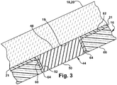
- the bracket 16 is attached to a window 18 of a vehicle (not shown). More particularly, the bracket 16 is attached to a windscreen or windshield 20 of an automotive vehicle (not shown). The bracket 16 may be attached or secured to the windshield 20 via a layer of adhesive 21 ( Fig. 3 ). The attachment or securement of the bracket 16 may be performed at the premises of the manufacturer of the windshield 20. Thus, when the windshield 20 is shipped or delivered to the manufacturer or assembler of the vehicle (not shown), the bracket 16 may already be attached to the windshield and ready to receive and retain the housing 12 with the vision device 14. The housing 12, which contains or supports the vision device 14, may then be installed or mounted in the bracket 16 after the windshield 20 is installed in the vehicle (not shown) on the assembly line of the vehicle manufacturer or assembler.
- the housing 12 may have any construction or configuration suitable to contain or support the vision device 14 and suitable to be received and retained in the bracket 16. As shown in Figs. 1 and 2 , the housing 12 has a generally rectangular configuration. At one end of the housing 12 are two laterally spaced apart tabs 22 and 24 that project away from the remainder of the housing along the length of the housing. At the opposite end of the housing 12 are two laterally spaced apart slots 26 and 28 that extend from an upper surface 30 (as viewed in Fig. 1 ) of the housing to a lower surface 32 (as viewed in Fig, 1 ) of the housing. The tabs 22 and 24 may be engaged by and retained in engagement with two complementarily shaped and laterally spaced apart hooks 34 (only one of which is shown in Fig.
- the slots 26 and 28 receive two laterally spaced apart arms 36 (only one of which is shown in Fig. 1 ) formed at the opposite longitudinal end of and in one piece with the bracket 16.
- Each of the arms 36 includes a projection 38 that engages a corresponding projection 40 on the housing 12.
- the arms 36 are flexible and resilient so that the projection 38 may snap over the projection 40 and so that the arms may resiliently urge the tabs 22 and 24 into engagement with the hooks 34.
- a recess 42 is formed in the upper surface 30 of the housing 12 adjacent to the slots 26 and 28.
- the recess 42 is outwardly and upwardly angled in a direction away from the slots 26 and 28 and toward the tabs 22 and 24.
- the vision device 14 is contained or mounted in the housing 12 so that the vision device has a view outwardly and upwardly from a position adjacent to the slots 26 and 28.
- the vision device 14 will have an unobstructed view through the windshield 20 toward the front of the vehicle (not shown), as indicated by the arrow F in Fig. 1 .
- the housing 12 in the space between the vision device 14 and the tabs 22 and 24 at the front or forward end of the housing, are various electronic components (not shown) for processing the information, in the form of electronic signals, obtained by the vision device.
- the electronic components may be mounted on one or more printed circuit boards (not shown) contained within the housing 12. In operation, the vision device 14 and the electronic components will generate heat, which will need to be dissipated to avoid thermal damage to the electronic components and/or the vision device.
- the bracket 16 mounts or carries a thermally conductive body 44.
- the thermally conductive body 44 may be received in a passage or opening 52 that extends through the bracket 16 from a first surface 62 to an opposed second surface 66 of the bracket.
- the upper surface of the thermally conductive body engages and presses against the windshield 20.
- Heat will then be conducted from the housing 12 through the thermally conductive body 44 into the windshield 20, where the heat can be more readily dissipated by, for example, air flow over the windshield, which has a much larger surface area for heat dissipation than the thermally conductive body, the housing or the bracket 16.
- the environment of the vision device 14 may thus be cooled or moderated via the vehicle windshield 20.
- the thermally conductive body 44 is made or formed of a material, such as a metal, with a thermal conductivity that is higher than the thermal conductivity of the material of which the bracket 16 is made or formed, which may be a plastic or polymer.
- the bracket 16 may be formed of nylon 6/6, which has a thermal conductivity of about 0.25 watts per meter Kelvin, while the thermally conductive body 44 may be formed of carbon steel, which has a thermal conductivity of about 43 watts per meter Kelvin.
- Other materials may be used to form or make the bracket 16 and the thermally conductive body 44, as desired.
- the use of a plastic or polymer to make or form the bracket 16 results in a relatively strong and lightweight bracket with desirable flexibility and resilience.
- thermally conductive body 44 results in a member with higher thermal conductivity and also greater weight per unit volume than a bracket 16 made or formed of plastic. Mounting a relatively small thermally conductive body 44 in a relatively larger bracket 16 provides desired thermal conductivity in a defined area without unduly increasing the total weight of the bracket and the thermally conductive body.
- plastics generally have thermal conductivities less than 1.0 watt per meter Kelvin
- metals generally have thermal conductivities substantially greater than 1.0 watt per meter Kelvin
- glass may have a thermal conductivity of about 1.0 watt per meter Kelvin
- the thermally conductive body 44 may be fabricated of a material have a thermal conductivity equal to or greater than 1.0 watt per meter Kelvin.
- the thermally conductive body 44 may have any convenient or desired shape, such as square or circular, with first and second opposed major side surfaces 48 and 50 ( Fig. 3 ).
- the thermally conductive body 44 is mounted in the bracket 16 in an orientation such that when the bracket is attached to the windshield 20, the first major side surface 48 is presented toward the windshield and the opposed second major side surface 50 is presented away from the windshield.
- the first major side surface 48 of the thermally conductive body 44 contacts and presses against an interior side surface 19 of the windshield 20.
- the thermally conductive body 44 may be mounted or carried in the bracket 16 such that the first major side surface 48 is disposed at a position or in a plane higher than or outward of the position or plane of a generally parallel adjacent portion of the first surface 62 of the bracket 16, as can be seen in Fig. 3 .
- the extent to which the thermally conductive body 44 projects or extends away from the adjacent portion of the first surface 62 of the bracket 16 is established or predetermined so as to ensure that the first major side surface 48 will be in close contact with the windshield 20 when the bracket 16 is attached to the windshield.
- the difference in the relative positions of the first major side surface 48 of the thermally conductive body 44 and the adjacent portion of the first surface 62 of the bracket 16 helps to ensure that the first major side surface contacts the interior side surface 19 of the windshield 20 before the adjacent portion of the first surface 62 of the bracket during the process of attaching or securing the bracket to the windshield.
- the difference in the relative positions of the first major side surface 48 of the thermally conductive body 44 and the adjacent portion of the first surface 62 of the bracket 16 also helps to ensure that the thickness of the adhesive layer 21 will not cause the first major side surface 48 to be held away from or spaced apart from the interior side surface 19 of the windshield 20.
- the thermally conductive body 44 may be mounted or carried in the bracket 16 using a narrow layer of an elastomeric material 64 interposed between and bonded or fixed to both the bracket and an outer periphery 60 of the thermally conductive body. Because the elastomeric material 64 is flexible, the thermally conductive body 44 will be permitted to move to a small extent relative to the bracket 16, in a downward direction as viewed in Fig. 3 , as the bracket is attached to the windshield 20.
- the thermally conductive body 44 will continue to be pressed against the interior side surface 19 of the windshield 20 as the bracket is attached to the windshield 20.
- the word “flexible” means that a material, such as the elastomeric material 64, is capable of being flexed, which is to say capable of being turned, bowed, or twisted without breaking.
- “resilient” means that a material, such as the elastomeric material 64, is capable of returning freely to a previous position, shape or condition, which is to say capable of recovering its size and shape after deformation.
- the first major side surface 48 of the thermally conductive body 44 and the interior side surface 19 of the windshield 20 may have complementary or substantially parallel surface contours. As depicted in Fig. 3 , the first major side surface 48 of the thermally conductive body 44 and the abutting or contacting portion of the interior side surface 19 of the windshield 20 are substantially flat.
- the first major side surface 48 of the thermally conductive body 44 and the abutting or contacting portion of the interior side surface 19 of the windshield 20 have a degree of flatness or parallelism necessary to achieve effective and efficient heat transfer, subject to commercial cost constraints and manufacturing efficiency.
- substantially flat surfaces are depicted in Fig. 3
- the first major side surface 48 of the thermally conductive body 44 and the abutting or contacting portion of the interior side surface 19 of the windshield 20 may have other complementary or parallel surface contours, as desired.
- the portion 46 of the upper surface 30 of the housing 12 located between the vision device 14 and the tabs 22 and 24 will contact the second major side surface 50 of the thermally conductive body 44 and will press against the second major side surface.
- the second major side surface 50 may project or extend a small distance away from an adjacent portion of the second surface 66 of the bracket 16.
- the portion 46 of the upper surface 30 of the housing 12 and the second major side surface 50 of the thermally conductive body 44 may have complementary or substantially parallel surface contours. As depicted in Fig.
- the portion 46 of the upper surface 30 of the housing 12 and the second major side surface 50 of the thermally conductive body 44 are substantially flat.
- the portion 46 of the upper surface 30 of the housing 12 and the second major side surface 50 of the thermally conductive body 44 have a degree of flatness or parallelism necessary to achieve effective and efficient heat transfer, subject to commercial cost constraints and manufacturing efficiency.
- substantially flat surfaces are depicted in Fig. 3
- the portion 46 of the upper surface 30 of the housing 12 and the second major side surface 50 of the thermally conductive body 44 may have other complementary or parallel surface contours, as desired.
- an optional thermally conductive member 68 may be mounted on or carried by the portion 46 of the upper surface 30 of the housing 12, as shown in Fig. 2 .
- the optional thermally conductive member 68 may have the same characteristics as the thermally conductive body 44 and may be mounted on or carried by the housing 12 in the same manner as the thermally conductive body 44 is mounted on or carried by the bracket 16.
- the thermally conductive member 68 may be made or formed of a material, such as a metal, with a thermal conductivity that is higher than the thermal conductivity of the material of which the housing 12 is made or formed, which may be a plastic or polymer.
- the thermally conductive member 68 may be mounted on or carried by the housing 12 such that a major side surface of the thermally conductive member is disposed at a position or in a plane higher than or outward of the position or plane of a generally parallel adjacent surface of the housing 12.
- the thermally conductive member 68 may also be mounted on or carried by the housing 12 using a narrow layer of an elastomeric material (not shown) interposed between and bonded or fixed to both the housing and an outer periphery of the thermally conductive member.
- a major side surface of the thermally conductive member 68 and the abutting or contacting portion of the thermally conductive body 44 may have complementary or substantially parallel surface contours.
- the system or apparatus 10 is described as being used to transfer heat from the housing 12 to the windshield 20 of a vehicle (not shown), the apparatus may also potentially be used to transfer heat from the windshield to the housing. Such heat transfer may potentially be useful in a situation in which the vehicle (not shown) has a relatively low interior temperature, but the atmospheric environment outside of the vehicle is sunny, thus heating the windshield more quickly than the interior of the vehicle in which the apparatus is mounted.
Landscapes
- Engineering & Computer Science (AREA)
- Mechanical Engineering (AREA)
- Aviation & Aerospace Engineering (AREA)
- Physics & Mathematics (AREA)
- General Physics & Mathematics (AREA)
- Multimedia (AREA)
- Signal Processing (AREA)
- Fittings On The Vehicle Exterior For Carrying Loads, And Devices For Holding Or Mounting Articles (AREA)
Claims (6)
- Eine Vorrichtung zum Helfen, eine Umgebungstemperatur einer Fahrerassistenzkamera (14) eines Fahrzeugs zu steuern, die Folgendes aufweist:ein Gehäuse (12), in dem die Fahrerassistenzkamera (14) anbringbar ist;eine Halterung (16), die eingerichtet und dimensioniert ist, das Gehäuse aufzunehmen und zu halten, wobei die Halterung (16) aus einem ersten Material mit einer ersten Wärmeleitfähigkeit gebildet ist, wobei die Halterung, wenn sie in einem Fahrzeug installiert ist, an einem Fenster (20) des Fahrzeugs angebracht ist; undeinen Körper (44), der aus einem zweiten Material mit einer zweiten Wärmeleitfähigkeit gebildet ist, wobei der Körper (44) an der Halterung (16) angebracht und in einer Öffnung (52) aufgenommen ist, die sich durch die Halterung (16) von einer ersten Oberfläche (62) der Halterung (16) zu einer gegenüberliegenden zweiten Oberfläche (66) der Halterung (16) erstreckt, wobei die zweite Wärmeleitfähigkeit größer als die erste Wärmeleitfähigkeit ist;wobei sich das Gehäuse (12), wenn es in der Halterung (16) aufgenommen ist, in unmittelbarer Nähe zum Körper (44) befindet, wobei der Körper (44), wenn die Halterung (16) an dem Fenster (20) des Fahrzeugs angebracht ist, das Fenster (20) berührt, um Wärme zwischen dem Fenster (20) und dem Gehäuse (16) zu übertragen, wobei dadurch die Umgebungstemperatur der Fahrerassistenzkamera (14) modifiziert wird.
- Die Vorrichtung nach Anspruch 1, wobei das Gehäuse (12), wenn es in der Halterung (16) aufgenommen ist, in Kontakt mit dem Körper (44) steht.
- Die Vorrichtung nach Anspruch 1, wobei das zweite Material eine Wärmeleitfähigkeit von mindestens 1 Watt pro Meter pro Kelvin aufweist.
- Die Vorrichtung nach Anspruch 1, wobei das erste Material ein Polymer und das zweite Material ein Metall ist.
- Die Vorrichtung nach Anspruch 1, die ein elastomeres Material (64) aufweist, das zwischen dem Körper (44) und der Halterung (16) angeordnet ist, das den Körper (44) an der Halterung (16) anbringt.
- Die Vorrichtung nach Anspruch 1, die ein Element (68) aufweist, das an dem Gehäuse (12) angebracht ist, wobei das Element (68), wenn das Gehäuse (12) in der Halterung (16) aufgenommen ist, den Körper (44) berührt, um Wärme zwischen dem Fenster (20) und dem Gehäuse über das Element (68) und den Körper (44) zu übertragen.
Applications Claiming Priority (1)
| Application Number | Priority Date | Filing Date | Title |
|---|---|---|---|
| US15/453,070 US10488738B2 (en) | 2017-03-08 | 2017-03-08 | Temperature management of a driver assist camera via a vehicle windshield |
Publications (2)
| Publication Number | Publication Date |
|---|---|
| EP3372452A1 EP3372452A1 (de) | 2018-09-12 |
| EP3372452B1 true EP3372452B1 (de) | 2019-09-18 |
Family
ID=61692183
Family Applications (1)
| Application Number | Title | Priority Date | Filing Date |
|---|---|---|---|
| EP18160086.7A Active EP3372452B1 (de) | 2017-03-08 | 2018-03-06 | Temperaturmanagement einer fahrerassistenzkamera über eine fahrzeugwindschutzscheibe |
Country Status (3)
| Country | Link |
|---|---|
| US (1) | US10488738B2 (de) |
| EP (1) | EP3372452B1 (de) |
| CN (1) | CN108569222B (de) |
Families Citing this family (3)
| Publication number | Priority date | Publication date | Assignee | Title |
|---|---|---|---|---|
| CN113260534B (zh) * | 2018-12-28 | 2024-08-09 | Zf主动安全和电子美国有限公司 | 驾驶员辅助系统 |
| US10981520B1 (en) * | 2019-11-14 | 2021-04-20 | Zf Friedrichshafen Ag | Driver assist system for a vehicle |
| FR3162180A1 (fr) * | 2024-05-14 | 2025-11-21 | Stellantis Auto Sas | Support d’objet pour véhicule automobile et véhicule automobile équipé d’un tel support d’objet |
Family Cites Families (13)
| Publication number | Priority date | Publication date | Assignee | Title |
|---|---|---|---|---|
| DE10237606B4 (de) * | 2002-08-16 | 2006-04-27 | Hella Kgaa Hueck & Co. | Kameraanordnung für Kraftfahrzeuge |
| US8256821B2 (en) * | 2004-12-15 | 2012-09-04 | Magna Donnelly Engineering Gmbh | Accessory module system for a vehicle window |
| US20070216768A1 (en) * | 2006-03-14 | 2007-09-20 | Ford Global Technologies, Llc | Device and method for outwardly looking ir camera mounted inside vehicles particularly suited for pre-crash sensing and pedestrian detection |
| DE102006059554B4 (de) * | 2006-12-16 | 2022-03-10 | Kostal Automobil Elektrik Gmbh & Co. Kg | Optoelektronische Sensoreinrichtung |
| US8339453B2 (en) | 2010-07-14 | 2012-12-25 | Trw Automotive U.S. Llc | Apparatus for use in association with a vehicle |
| US20150042874A1 (en) * | 2013-08-08 | 2015-02-12 | Nidec Elesys Corporation | In-vehicle camera |
| JP6413754B2 (ja) | 2014-03-10 | 2018-10-31 | 株式会社デンソー | 撮像装置および撮像装置を備えた車載装置 |
| JP2016014564A (ja) * | 2014-07-01 | 2016-01-28 | 株式会社リコー | 撮像ユニット |
| JP6052246B2 (ja) * | 2014-07-10 | 2016-12-27 | トヨタ自動車株式会社 | 車載カメラの取り付け構造 |
| JP6303974B2 (ja) * | 2014-10-22 | 2018-04-04 | 株式会社デンソー | 車載カメラ装置及び車載システム |
| JP6197812B2 (ja) * | 2015-03-05 | 2017-09-20 | トヨタ自動車株式会社 | 車載用カメラの取付構造 |
| JP6421691B2 (ja) * | 2015-04-28 | 2018-11-14 | 株式会社デンソー | カメラ装置 |
| JP6390512B2 (ja) | 2015-05-21 | 2018-09-19 | 株式会社デンソー | 車載カメラ装置 |
-
2017
- 2017-03-08 US US15/453,070 patent/US10488738B2/en active Active
-
2018
- 2018-03-06 EP EP18160086.7A patent/EP3372452B1/de active Active
- 2018-03-08 CN CN201810188713.3A patent/CN108569222B/zh not_active Expired - Fee Related
Non-Patent Citations (1)
| Title |
|---|
| None * |
Also Published As
| Publication number | Publication date |
|---|---|
| US20180259830A1 (en) | 2018-09-13 |
| CN108569222B (zh) | 2022-03-01 |
| CN108569222A (zh) | 2018-09-25 |
| US10488738B2 (en) | 2019-11-26 |
| EP3372452A1 (de) | 2018-09-12 |
Similar Documents
| Publication | Publication Date | Title |
|---|---|---|
| US10288986B2 (en) | Moderation of a driver assist camera enhancement via a vehicle windshield | |
| US11689791B2 (en) | Vehicular camera module | |
| US9854225B2 (en) | Imaging unit including a chassis and heat transfer member | |
| JP7312164B2 (ja) | レンズユニットおよびカメラモジュール | |
| US10209512B2 (en) | Camera heater for advanced driver assistance system | |
| EP3372452B1 (de) | Temperaturmanagement einer fahrerassistenzkamera über eine fahrzeugwindschutzscheibe | |
| US9544487B2 (en) | Camera system with image sensor contacting metallic housing via heat conducting element | |
| CN104717410A (zh) | 装配加热元件的摄像头 | |
| CN111983766A (zh) | 光学镜头及成像模组 | |
| JP2017118445A (ja) | 車載カメラ | |
| CN103340010A (zh) | 用于交通工具内图像记录仪的装置 | |
| CN113165578B (zh) | 用于车载图像采集单元的可加热装置 | |
| JP7328398B2 (ja) | 電子機器、撮像装置、および移動体 | |
| EP2876873B1 (de) | Teilerdung, elektronische Vorrichtung, Bildgebungsvorrichtung und Erdungsteilherstellungsverfahren | |
| JP7541844B2 (ja) | 撮像装置および車両 | |
| CN114390164A (zh) | 成像设备 | |
| JP6897750B2 (ja) | 撮像ユニット | |
| US20220244623A1 (en) | Camera support structure and head-mounted display | |
| US20240053663A1 (en) | Image capturing unit | |
| CN217216725U (zh) | 摄像装置及车舱内影像的处理系统 | |
| WO2017125477A1 (en) | Antenna module for a motor vehicle, driver assistance system as well as motor vehicle | |
| US12538004B2 (en) | Imaging device | |
| JP7624693B2 (ja) | 車載機器、電子機器及び取付部材等 | |
| US11997373B2 (en) | Camera module for a vehicle | |
| CN218886376U (zh) | 一种具有除霜除雾功能的镜头 |
Legal Events
| Date | Code | Title | Description |
|---|---|---|---|
| PUAI | Public reference made under article 153(3) epc to a published international application that has entered the european phase |
Free format text: ORIGINAL CODE: 0009012 |
|
| STAA | Information on the status of an ep patent application or granted ep patent |
Free format text: STATUS: THE APPLICATION HAS BEEN PUBLISHED |
|
| AK | Designated contracting states |
Kind code of ref document: A1 Designated state(s): AL AT BE BG CH CY CZ DE DK EE ES FI FR GB GR HR HU IE IS IT LI LT LU LV MC MK MT NL NO PL PT RO RS SE SI SK SM TR |
|
| AX | Request for extension of the european patent |
Extension state: BA ME |
|
| STAA | Information on the status of an ep patent application or granted ep patent |
Free format text: STATUS: REQUEST FOR EXAMINATION WAS MADE |
|
| 17P | Request for examination filed |
Effective date: 20190312 |
|
| RBV | Designated contracting states (corrected) |
Designated state(s): AL AT BE BG CH CY CZ DE DK EE ES FI FR GB GR HR HU IE IS IT LI LT LU LV MC MK MT NL NO PL PT RO RS SE SI SK SM TR |
|
| GRAP | Despatch of communication of intention to grant a patent |
Free format text: ORIGINAL CODE: EPIDOSNIGR1 |
|
| STAA | Information on the status of an ep patent application or granted ep patent |
Free format text: STATUS: GRANT OF PATENT IS INTENDED |
|
| INTG | Intention to grant announced |
Effective date: 20190426 |
|
| GRAS | Grant fee paid |
Free format text: ORIGINAL CODE: EPIDOSNIGR3 |
|
| GRAA | (expected) grant |
Free format text: ORIGINAL CODE: 0009210 |
|
| STAA | Information on the status of an ep patent application or granted ep patent |
Free format text: STATUS: THE PATENT HAS BEEN GRANTED |
|
| AK | Designated contracting states |
Kind code of ref document: B1 Designated state(s): AL AT BE BG CH CY CZ DE DK EE ES FI FR GB GR HR HU IE IS IT LI LT LU LV MC MK MT NL NO PL PT RO RS SE SI SK SM TR |
|
| REG | Reference to a national code |
Ref country code: GB Ref legal event code: FG4D |
|
| REG | Reference to a national code |
Ref country code: CH Ref legal event code: EP |
|
| REG | Reference to a national code |
Ref country code: DE Ref legal event code: R096 Ref document number: 602018000661 Country of ref document: DE |
|
| REG | Reference to a national code |
Ref country code: AT Ref legal event code: REF Ref document number: 1180899 Country of ref document: AT Kind code of ref document: T Effective date: 20191015 |
|
| REG | Reference to a national code |
Ref country code: IE Ref legal event code: FG4D |
|
| REG | Reference to a national code |
Ref country code: NL Ref legal event code: MP Effective date: 20190918 |
|
| PG25 | Lapsed in a contracting state [announced via postgrant information from national office to epo] |
Ref country code: FI Free format text: LAPSE BECAUSE OF FAILURE TO SUBMIT A TRANSLATION OF THE DESCRIPTION OR TO PAY THE FEE WITHIN THE PRESCRIBED TIME-LIMIT Effective date: 20190918 Ref country code: HR Free format text: LAPSE BECAUSE OF FAILURE TO SUBMIT A TRANSLATION OF THE DESCRIPTION OR TO PAY THE FEE WITHIN THE PRESCRIBED TIME-LIMIT Effective date: 20190918 Ref country code: LT Free format text: LAPSE BECAUSE OF FAILURE TO SUBMIT A TRANSLATION OF THE DESCRIPTION OR TO PAY THE FEE WITHIN THE PRESCRIBED TIME-LIMIT Effective date: 20190918 Ref country code: SE Free format text: LAPSE BECAUSE OF FAILURE TO SUBMIT A TRANSLATION OF THE DESCRIPTION OR TO PAY THE FEE WITHIN THE PRESCRIBED TIME-LIMIT Effective date: 20190918 Ref country code: BG Free format text: LAPSE BECAUSE OF FAILURE TO SUBMIT A TRANSLATION OF THE DESCRIPTION OR TO PAY THE FEE WITHIN THE PRESCRIBED TIME-LIMIT Effective date: 20191218 Ref country code: NO Free format text: LAPSE BECAUSE OF FAILURE TO SUBMIT A TRANSLATION OF THE DESCRIPTION OR TO PAY THE FEE WITHIN THE PRESCRIBED TIME-LIMIT Effective date: 20191218 |
|
| REG | Reference to a national code |
Ref country code: LT Ref legal event code: MG4D |
|
| PG25 | Lapsed in a contracting state [announced via postgrant information from national office to epo] |
Ref country code: AL Free format text: LAPSE BECAUSE OF FAILURE TO SUBMIT A TRANSLATION OF THE DESCRIPTION OR TO PAY THE FEE WITHIN THE PRESCRIBED TIME-LIMIT Effective date: 20190918 Ref country code: GR Free format text: LAPSE BECAUSE OF FAILURE TO SUBMIT A TRANSLATION OF THE DESCRIPTION OR TO PAY THE FEE WITHIN THE PRESCRIBED TIME-LIMIT Effective date: 20191219 Ref country code: LV Free format text: LAPSE BECAUSE OF FAILURE TO SUBMIT A TRANSLATION OF THE DESCRIPTION OR TO PAY THE FEE WITHIN THE PRESCRIBED TIME-LIMIT Effective date: 20190918 Ref country code: RS Free format text: LAPSE BECAUSE OF FAILURE TO SUBMIT A TRANSLATION OF THE DESCRIPTION OR TO PAY THE FEE WITHIN THE PRESCRIBED TIME-LIMIT Effective date: 20190918 |
|
| REG | Reference to a national code |
Ref country code: AT Ref legal event code: MK05 Ref document number: 1180899 Country of ref document: AT Kind code of ref document: T Effective date: 20190918 |
|
| PG25 | Lapsed in a contracting state [announced via postgrant information from national office to epo] |
Ref country code: EE Free format text: LAPSE BECAUSE OF FAILURE TO SUBMIT A TRANSLATION OF THE DESCRIPTION OR TO PAY THE FEE WITHIN THE PRESCRIBED TIME-LIMIT Effective date: 20190918 Ref country code: PT Free format text: LAPSE BECAUSE OF FAILURE TO SUBMIT A TRANSLATION OF THE DESCRIPTION OR TO PAY THE FEE WITHIN THE PRESCRIBED TIME-LIMIT Effective date: 20200120 Ref country code: PL Free format text: LAPSE BECAUSE OF FAILURE TO SUBMIT A TRANSLATION OF THE DESCRIPTION OR TO PAY THE FEE WITHIN THE PRESCRIBED TIME-LIMIT Effective date: 20190918 Ref country code: RO Free format text: LAPSE BECAUSE OF FAILURE TO SUBMIT A TRANSLATION OF THE DESCRIPTION OR TO PAY THE FEE WITHIN THE PRESCRIBED TIME-LIMIT Effective date: 20190918 Ref country code: IT Free format text: LAPSE BECAUSE OF FAILURE TO SUBMIT A TRANSLATION OF THE DESCRIPTION OR TO PAY THE FEE WITHIN THE PRESCRIBED TIME-LIMIT Effective date: 20190918 Ref country code: NL Free format text: LAPSE BECAUSE OF FAILURE TO SUBMIT A TRANSLATION OF THE DESCRIPTION OR TO PAY THE FEE WITHIN THE PRESCRIBED TIME-LIMIT Effective date: 20190918 Ref country code: AT Free format text: LAPSE BECAUSE OF FAILURE TO SUBMIT A TRANSLATION OF THE DESCRIPTION OR TO PAY THE FEE WITHIN THE PRESCRIBED TIME-LIMIT Effective date: 20190918 Ref country code: ES Free format text: LAPSE BECAUSE OF FAILURE TO SUBMIT A TRANSLATION OF THE DESCRIPTION OR TO PAY THE FEE WITHIN THE PRESCRIBED TIME-LIMIT Effective date: 20190918 |
|
| PG25 | Lapsed in a contracting state [announced via postgrant information from national office to epo] |
Ref country code: IS Free format text: LAPSE BECAUSE OF FAILURE TO SUBMIT A TRANSLATION OF THE DESCRIPTION OR TO PAY THE FEE WITHIN THE PRESCRIBED TIME-LIMIT Effective date: 20200224 Ref country code: SK Free format text: LAPSE BECAUSE OF FAILURE TO SUBMIT A TRANSLATION OF THE DESCRIPTION OR TO PAY THE FEE WITHIN THE PRESCRIBED TIME-LIMIT Effective date: 20190918 Ref country code: SM Free format text: LAPSE BECAUSE OF FAILURE TO SUBMIT A TRANSLATION OF THE DESCRIPTION OR TO PAY THE FEE WITHIN THE PRESCRIBED TIME-LIMIT Effective date: 20190918 Ref country code: CZ Free format text: LAPSE BECAUSE OF FAILURE TO SUBMIT A TRANSLATION OF THE DESCRIPTION OR TO PAY THE FEE WITHIN THE PRESCRIBED TIME-LIMIT Effective date: 20190918 |
|
| REG | Reference to a national code |
Ref country code: DE Ref legal event code: R097 Ref document number: 602018000661 Country of ref document: DE |
|
| PLBE | No opposition filed within time limit |
Free format text: ORIGINAL CODE: 0009261 |
|
| STAA | Information on the status of an ep patent application or granted ep patent |
Free format text: STATUS: NO OPPOSITION FILED WITHIN TIME LIMIT |
|
| PG2D | Information on lapse in contracting state deleted |
Ref country code: IS |
|
| PG25 | Lapsed in a contracting state [announced via postgrant information from national office to epo] |
Ref country code: DK Free format text: LAPSE BECAUSE OF FAILURE TO SUBMIT A TRANSLATION OF THE DESCRIPTION OR TO PAY THE FEE WITHIN THE PRESCRIBED TIME-LIMIT Effective date: 20190918 Ref country code: IS Free format text: LAPSE BECAUSE OF FAILURE TO SUBMIT A TRANSLATION OF THE DESCRIPTION OR TO PAY THE FEE WITHIN THE PRESCRIBED TIME-LIMIT Effective date: 20200119 |
|
| 26N | No opposition filed |
Effective date: 20200619 |
|
| PG25 | Lapsed in a contracting state [announced via postgrant information from national office to epo] |
Ref country code: SI Free format text: LAPSE BECAUSE OF FAILURE TO SUBMIT A TRANSLATION OF THE DESCRIPTION OR TO PAY THE FEE WITHIN THE PRESCRIBED TIME-LIMIT Effective date: 20190918 |
|
| PG25 | Lapsed in a contracting state [announced via postgrant information from national office to epo] |
Ref country code: MC Free format text: LAPSE BECAUSE OF FAILURE TO SUBMIT A TRANSLATION OF THE DESCRIPTION OR TO PAY THE FEE WITHIN THE PRESCRIBED TIME-LIMIT Effective date: 20190918 |
|
| REG | Reference to a national code |
Ref country code: BE Ref legal event code: MM Effective date: 20200331 |
|
| PG25 | Lapsed in a contracting state [announced via postgrant information from national office to epo] |
Ref country code: LU Free format text: LAPSE BECAUSE OF NON-PAYMENT OF DUE FEES Effective date: 20200306 |
|
| PG25 | Lapsed in a contracting state [announced via postgrant information from national office to epo] |
Ref country code: IE Free format text: LAPSE BECAUSE OF NON-PAYMENT OF DUE FEES Effective date: 20200306 |
|
| PG25 | Lapsed in a contracting state [announced via postgrant information from national office to epo] |
Ref country code: BE Free format text: LAPSE BECAUSE OF NON-PAYMENT OF DUE FEES Effective date: 20200331 |
|
| REG | Reference to a national code |
Ref country code: CH Ref legal event code: PL |
|
| PG25 | Lapsed in a contracting state [announced via postgrant information from national office to epo] |
Ref country code: LI Free format text: LAPSE BECAUSE OF NON-PAYMENT OF DUE FEES Effective date: 20210331 Ref country code: CH Free format text: LAPSE BECAUSE OF NON-PAYMENT OF DUE FEES Effective date: 20210331 |
|
| PG25 | Lapsed in a contracting state [announced via postgrant information from national office to epo] |
Ref country code: TR Free format text: LAPSE BECAUSE OF FAILURE TO SUBMIT A TRANSLATION OF THE DESCRIPTION OR TO PAY THE FEE WITHIN THE PRESCRIBED TIME-LIMIT Effective date: 20190918 Ref country code: MT Free format text: LAPSE BECAUSE OF FAILURE TO SUBMIT A TRANSLATION OF THE DESCRIPTION OR TO PAY THE FEE WITHIN THE PRESCRIBED TIME-LIMIT Effective date: 20190918 Ref country code: CY Free format text: LAPSE BECAUSE OF FAILURE TO SUBMIT A TRANSLATION OF THE DESCRIPTION OR TO PAY THE FEE WITHIN THE PRESCRIBED TIME-LIMIT Effective date: 20190918 |
|
| PG25 | Lapsed in a contracting state [announced via postgrant information from national office to epo] |
Ref country code: MK Free format text: LAPSE BECAUSE OF FAILURE TO SUBMIT A TRANSLATION OF THE DESCRIPTION OR TO PAY THE FEE WITHIN THE PRESCRIBED TIME-LIMIT Effective date: 20190918 |
|
| PGFP | Annual fee paid to national office [announced via postgrant information from national office to epo] |
Ref country code: FR Payment date: 20230110 Year of fee payment: 6 |
|
| PGFP | Annual fee paid to national office [announced via postgrant information from national office to epo] |
Ref country code: GB Payment date: 20230112 Year of fee payment: 6 Ref country code: DE Payment date: 20230110 Year of fee payment: 6 |
|
| P01 | Opt-out of the competence of the unified patent court (upc) registered |
Effective date: 20230628 |
|
| REG | Reference to a national code |
Ref country code: DE Ref legal event code: R119 Ref document number: 602018000661 Country of ref document: DE |
|
| GBPC | Gb: european patent ceased through non-payment of renewal fee |
Effective date: 20240306 |
|
| PG25 | Lapsed in a contracting state [announced via postgrant information from national office to epo] |
Ref country code: DE Free format text: LAPSE BECAUSE OF NON-PAYMENT OF DUE FEES Effective date: 20241001 |
|
| PG25 | Lapsed in a contracting state [announced via postgrant information from national office to epo] |
Ref country code: GB Free format text: LAPSE BECAUSE OF NON-PAYMENT OF DUE FEES Effective date: 20240306 |
|
| PG25 | Lapsed in a contracting state [announced via postgrant information from national office to epo] |
Ref country code: FR Free format text: LAPSE BECAUSE OF NON-PAYMENT OF DUE FEES Effective date: 20240331 |
|
| PG25 | Lapsed in a contracting state [announced via postgrant information from national office to epo] |
Ref country code: GB Free format text: LAPSE BECAUSE OF NON-PAYMENT OF DUE FEES Effective date: 20240306 Ref country code: FR Free format text: LAPSE BECAUSE OF NON-PAYMENT OF DUE FEES Effective date: 20240331 Ref country code: DE Free format text: LAPSE BECAUSE OF NON-PAYMENT OF DUE FEES Effective date: 20241001 |