EP3372452B1 - Temperature management of a driver assist camera via a vehicle windshield - Google Patents
Temperature management of a driver assist camera via a vehicle windshield Download PDFInfo
- Publication number
- EP3372452B1 EP3372452B1 EP18160086.7A EP18160086A EP3372452B1 EP 3372452 B1 EP3372452 B1 EP 3372452B1 EP 18160086 A EP18160086 A EP 18160086A EP 3372452 B1 EP3372452 B1 EP 3372452B1
- Authority
- EP
- European Patent Office
- Prior art keywords
- bracket
- housing
- thermally conductive
- windshield
- conductive body
- Prior art date
- Legal status (The legal status is an assumption and is not a legal conclusion. Google has not performed a legal analysis and makes no representation as to the accuracy of the status listed.)
- Active
Links
Images

Classifications
-
- B—PERFORMING OPERATIONS; TRANSPORTING
- B60—VEHICLES IN GENERAL
- B60R—VEHICLES, VEHICLE FITTINGS, OR VEHICLE PARTS, NOT OTHERWISE PROVIDED FOR
- B60R11/00—Arrangements for holding or mounting articles, not otherwise provided for
- B60R11/04—Mounting of cameras operative during drive; Arrangement of controls thereof relative to the vehicle
-
- G—PHYSICS
- G03—PHOTOGRAPHY; CINEMATOGRAPHY; ANALOGOUS TECHNIQUES USING WAVES OTHER THAN OPTICAL WAVES; ELECTROGRAPHY; HOLOGRAPHY
- G03B—APPARATUS OR ARRANGEMENTS FOR TAKING PHOTOGRAPHS OR FOR PROJECTING OR VIEWING THEM; APPARATUS OR ARRANGEMENTS EMPLOYING ANALOGOUS TECHNIQUES USING WAVES OTHER THAN OPTICAL WAVES; ACCESSORIES THEREFOR
- G03B17/00—Details of cameras or camera bodies; Accessories therefor
- G03B17/55—Details of cameras or camera bodies; Accessories therefor with provision for heating or cooling, e.g. in aircraft
-
- H—ELECTRICITY
- H04—ELECTRIC COMMUNICATION TECHNIQUE
- H04N—PICTORIAL COMMUNICATION, e.g. TELEVISION
- H04N23/00—Cameras or camera modules comprising electronic image sensors; Control thereof
- H04N23/50—Constructional details
- H04N23/51—Housings
-
- B—PERFORMING OPERATIONS; TRANSPORTING
- B60—VEHICLES IN GENERAL
- B60R—VEHICLES, VEHICLE FITTINGS, OR VEHICLE PARTS, NOT OTHERWISE PROVIDED FOR
- B60R11/00—Arrangements for holding or mounting articles, not otherwise provided for
- B60R2011/0042—Arrangements for holding or mounting articles, not otherwise provided for characterised by mounting means
- B60R2011/0049—Arrangements for holding or mounting articles, not otherwise provided for characterised by mounting means for non integrated articles
- B60R2011/005—Connection with the vehicle part
- B60R2011/0063—Connection with the vehicle part using adhesive means, e.g. hook and loop fasteners
-
- B—PERFORMING OPERATIONS; TRANSPORTING
- B60—VEHICLES IN GENERAL
- B60R—VEHICLES, VEHICLE FITTINGS, OR VEHICLE PARTS, NOT OTHERWISE PROVIDED FOR
- B60R11/00—Arrangements for holding or mounting articles, not otherwise provided for
- B60R2011/0042—Arrangements for holding or mounting articles, not otherwise provided for characterised by mounting means
- B60R2011/0049—Arrangements for holding or mounting articles, not otherwise provided for characterised by mounting means for non integrated articles
- B60R2011/0064—Connection with the article
- B60R2011/0075—Connection with the article using a containment or docking space
Definitions
- the present invention relates to an apparatus to help manage the temperature of an environment of a driver assist (“DAS”) camera via a vehicle windshield.
- DAS driver assist
- DAS cameras are incorporated in a vehicle to acquire information and provide the acquired information to a vehicle safety system designed to assist the driver.
- a DAS camera may be mounted on or near the vehicle windshield to ensure a desired field of view.
- the DAS camera and its mounting system should be as small as possible to reduce interference with sight lines through the windshield.
- multiple electronic components are mounted adjacent to the DAS camera to process the information acquired by the DAS camera and communicate the processed information via electronic signals to one or more other systems within the vehicle.
- the DAS camera and the associated electronic components will emanate substantial heat that requires dissipation to avoid thermal damage to the DAS camera and/or the adjacent or associated electronic components.
- US 2016 006 911 A1 related to an imaging unit which includes a plurality of imaging devices configured to capture images of an object; a circuit substrate configured to generate image data based on the images captured by the imaging devices; a chassis that holds the imaging devices; and a heat transfer member including a contacting portion configured to contact an installed member in a case where the imaging unit is installed on the installed member.
- the heat transfer member contacts the chassis or the circuit substrate, and heat conductivity of the heat transfer member is greater than the heat conductivity of the chassis.
- US 2016 344 977 A1 relates to an on-board camera apparatus, which includes a camera module, a control circuit board, a housing, a bracket, and a hood.
- the housing houses the camera module and the control circuit board.
- the bracket fixes the housing to a front windshield of the vehicle.
- the present invention is directed to an apparatus to help manage the temperature of an environment of a DAS camera via a vehicle windshield and, more particularly, to an apparatus for modifying a temperature in an environment of a DAS camera via the vehicle windshield or windscreen.
- an apparatus for helping to manage a temperature of an environment of a driver assist camera of a vehicle inter alia comprises (a) a housing in which the driver assist camera is mountable and (b) a bracket configured and dimensioned to receive and retain the housing.
- the bracket is formed of a first material having a first thermal conductivity.
- the bracket when installed in a vehicle is attached to a window of the vehicle.
- the apparatus also comprises a body formed of a second material having a second thermal conductivity.
- the body is mounted on the bracket.
- the second thermal conductivity is greater than the first thermal conductivity.
- the housing when received in the bracket is in close proximity to the body.
- the body when the bracket is attached to the window of the vehicle contacts the window so as to transfer heat between the window and the housing, thereby modifying the temperature of the environment of the driver assist camera.
- Fig. 1 illustrates a system or apparatus 10 for moderating the environment around a DAS camera in accordance with an example embodiment of the present invention.
- the apparatus 10 includes a housing 12 that contains or supports a vision device 14 ( Fig. 2 ), such as a CCD or CMOS camera.
- the apparatus 10 also includes a bracket 16 configured and dimensioned to receive and retain the housing 12.
- the bracket 16 is attached to a window 18 of a vehicle (not shown). More particularly, the bracket 16 is attached to a windscreen or windshield 20 of an automotive vehicle (not shown). The bracket 16 may be attached or secured to the windshield 20 via a layer of adhesive 21 ( Fig. 3 ). The attachment or securement of the bracket 16 may be performed at the premises of the manufacturer of the windshield 20. Thus, when the windshield 20 is shipped or delivered to the manufacturer or assembler of the vehicle (not shown), the bracket 16 may already be attached to the windshield and ready to receive and retain the housing 12 with the vision device 14. The housing 12, which contains or supports the vision device 14, may then be installed or mounted in the bracket 16 after the windshield 20 is installed in the vehicle (not shown) on the assembly line of the vehicle manufacturer or assembler.
- the housing 12 may have any construction or configuration suitable to contain or support the vision device 14 and suitable to be received and retained in the bracket 16. As shown in Figs. 1 and 2 , the housing 12 has a generally rectangular configuration. At one end of the housing 12 are two laterally spaced apart tabs 22 and 24 that project away from the remainder of the housing along the length of the housing. At the opposite end of the housing 12 are two laterally spaced apart slots 26 and 28 that extend from an upper surface 30 (as viewed in Fig. 1 ) of the housing to a lower surface 32 (as viewed in Fig, 1 ) of the housing. The tabs 22 and 24 may be engaged by and retained in engagement with two complementarily shaped and laterally spaced apart hooks 34 (only one of which is shown in Fig.
- the slots 26 and 28 receive two laterally spaced apart arms 36 (only one of which is shown in Fig. 1 ) formed at the opposite longitudinal end of and in one piece with the bracket 16.
- Each of the arms 36 includes a projection 38 that engages a corresponding projection 40 on the housing 12.
- the arms 36 are flexible and resilient so that the projection 38 may snap over the projection 40 and so that the arms may resiliently urge the tabs 22 and 24 into engagement with the hooks 34.
- a recess 42 is formed in the upper surface 30 of the housing 12 adjacent to the slots 26 and 28.
- the recess 42 is outwardly and upwardly angled in a direction away from the slots 26 and 28 and toward the tabs 22 and 24.
- the vision device 14 is contained or mounted in the housing 12 so that the vision device has a view outwardly and upwardly from a position adjacent to the slots 26 and 28.
- the vision device 14 will have an unobstructed view through the windshield 20 toward the front of the vehicle (not shown), as indicated by the arrow F in Fig. 1 .
- the housing 12 in the space between the vision device 14 and the tabs 22 and 24 at the front or forward end of the housing, are various electronic components (not shown) for processing the information, in the form of electronic signals, obtained by the vision device.
- the electronic components may be mounted on one or more printed circuit boards (not shown) contained within the housing 12. In operation, the vision device 14 and the electronic components will generate heat, which will need to be dissipated to avoid thermal damage to the electronic components and/or the vision device.
- the bracket 16 mounts or carries a thermally conductive body 44.
- the thermally conductive body 44 may be received in a passage or opening 52 that extends through the bracket 16 from a first surface 62 to an opposed second surface 66 of the bracket.
- the upper surface of the thermally conductive body engages and presses against the windshield 20.
- Heat will then be conducted from the housing 12 through the thermally conductive body 44 into the windshield 20, where the heat can be more readily dissipated by, for example, air flow over the windshield, which has a much larger surface area for heat dissipation than the thermally conductive body, the housing or the bracket 16.
- the environment of the vision device 14 may thus be cooled or moderated via the vehicle windshield 20.
- the thermally conductive body 44 is made or formed of a material, such as a metal, with a thermal conductivity that is higher than the thermal conductivity of the material of which the bracket 16 is made or formed, which may be a plastic or polymer.
- the bracket 16 may be formed of nylon 6/6, which has a thermal conductivity of about 0.25 watts per meter Kelvin, while the thermally conductive body 44 may be formed of carbon steel, which has a thermal conductivity of about 43 watts per meter Kelvin.
- Other materials may be used to form or make the bracket 16 and the thermally conductive body 44, as desired.
- the use of a plastic or polymer to make or form the bracket 16 results in a relatively strong and lightweight bracket with desirable flexibility and resilience.
- thermally conductive body 44 results in a member with higher thermal conductivity and also greater weight per unit volume than a bracket 16 made or formed of plastic. Mounting a relatively small thermally conductive body 44 in a relatively larger bracket 16 provides desired thermal conductivity in a defined area without unduly increasing the total weight of the bracket and the thermally conductive body.
- plastics generally have thermal conductivities less than 1.0 watt per meter Kelvin
- metals generally have thermal conductivities substantially greater than 1.0 watt per meter Kelvin
- glass may have a thermal conductivity of about 1.0 watt per meter Kelvin
- the thermally conductive body 44 may be fabricated of a material have a thermal conductivity equal to or greater than 1.0 watt per meter Kelvin.
- the thermally conductive body 44 may have any convenient or desired shape, such as square or circular, with first and second opposed major side surfaces 48 and 50 ( Fig. 3 ).
- the thermally conductive body 44 is mounted in the bracket 16 in an orientation such that when the bracket is attached to the windshield 20, the first major side surface 48 is presented toward the windshield and the opposed second major side surface 50 is presented away from the windshield.
- the first major side surface 48 of the thermally conductive body 44 contacts and presses against an interior side surface 19 of the windshield 20.
- the thermally conductive body 44 may be mounted or carried in the bracket 16 such that the first major side surface 48 is disposed at a position or in a plane higher than or outward of the position or plane of a generally parallel adjacent portion of the first surface 62 of the bracket 16, as can be seen in Fig. 3 .
- the extent to which the thermally conductive body 44 projects or extends away from the adjacent portion of the first surface 62 of the bracket 16 is established or predetermined so as to ensure that the first major side surface 48 will be in close contact with the windshield 20 when the bracket 16 is attached to the windshield.
- the difference in the relative positions of the first major side surface 48 of the thermally conductive body 44 and the adjacent portion of the first surface 62 of the bracket 16 helps to ensure that the first major side surface contacts the interior side surface 19 of the windshield 20 before the adjacent portion of the first surface 62 of the bracket during the process of attaching or securing the bracket to the windshield.
- the difference in the relative positions of the first major side surface 48 of the thermally conductive body 44 and the adjacent portion of the first surface 62 of the bracket 16 also helps to ensure that the thickness of the adhesive layer 21 will not cause the first major side surface 48 to be held away from or spaced apart from the interior side surface 19 of the windshield 20.
- the thermally conductive body 44 may be mounted or carried in the bracket 16 using a narrow layer of an elastomeric material 64 interposed between and bonded or fixed to both the bracket and an outer periphery 60 of the thermally conductive body. Because the elastomeric material 64 is flexible, the thermally conductive body 44 will be permitted to move to a small extent relative to the bracket 16, in a downward direction as viewed in Fig. 3 , as the bracket is attached to the windshield 20.
- the thermally conductive body 44 will continue to be pressed against the interior side surface 19 of the windshield 20 as the bracket is attached to the windshield 20.
- the word “flexible” means that a material, such as the elastomeric material 64, is capable of being flexed, which is to say capable of being turned, bowed, or twisted without breaking.
- “resilient” means that a material, such as the elastomeric material 64, is capable of returning freely to a previous position, shape or condition, which is to say capable of recovering its size and shape after deformation.
- the first major side surface 48 of the thermally conductive body 44 and the interior side surface 19 of the windshield 20 may have complementary or substantially parallel surface contours. As depicted in Fig. 3 , the first major side surface 48 of the thermally conductive body 44 and the abutting or contacting portion of the interior side surface 19 of the windshield 20 are substantially flat.
- the first major side surface 48 of the thermally conductive body 44 and the abutting or contacting portion of the interior side surface 19 of the windshield 20 have a degree of flatness or parallelism necessary to achieve effective and efficient heat transfer, subject to commercial cost constraints and manufacturing efficiency.
- substantially flat surfaces are depicted in Fig. 3
- the first major side surface 48 of the thermally conductive body 44 and the abutting or contacting portion of the interior side surface 19 of the windshield 20 may have other complementary or parallel surface contours, as desired.
- the portion 46 of the upper surface 30 of the housing 12 located between the vision device 14 and the tabs 22 and 24 will contact the second major side surface 50 of the thermally conductive body 44 and will press against the second major side surface.
- the second major side surface 50 may project or extend a small distance away from an adjacent portion of the second surface 66 of the bracket 16.
- the portion 46 of the upper surface 30 of the housing 12 and the second major side surface 50 of the thermally conductive body 44 may have complementary or substantially parallel surface contours. As depicted in Fig.
- the portion 46 of the upper surface 30 of the housing 12 and the second major side surface 50 of the thermally conductive body 44 are substantially flat.
- the portion 46 of the upper surface 30 of the housing 12 and the second major side surface 50 of the thermally conductive body 44 have a degree of flatness or parallelism necessary to achieve effective and efficient heat transfer, subject to commercial cost constraints and manufacturing efficiency.
- substantially flat surfaces are depicted in Fig. 3
- the portion 46 of the upper surface 30 of the housing 12 and the second major side surface 50 of the thermally conductive body 44 may have other complementary or parallel surface contours, as desired.
- an optional thermally conductive member 68 may be mounted on or carried by the portion 46 of the upper surface 30 of the housing 12, as shown in Fig. 2 .
- the optional thermally conductive member 68 may have the same characteristics as the thermally conductive body 44 and may be mounted on or carried by the housing 12 in the same manner as the thermally conductive body 44 is mounted on or carried by the bracket 16.
- the thermally conductive member 68 may be made or formed of a material, such as a metal, with a thermal conductivity that is higher than the thermal conductivity of the material of which the housing 12 is made or formed, which may be a plastic or polymer.
- the thermally conductive member 68 may be mounted on or carried by the housing 12 such that a major side surface of the thermally conductive member is disposed at a position or in a plane higher than or outward of the position or plane of a generally parallel adjacent surface of the housing 12.
- the thermally conductive member 68 may also be mounted on or carried by the housing 12 using a narrow layer of an elastomeric material (not shown) interposed between and bonded or fixed to both the housing and an outer periphery of the thermally conductive member.
- a major side surface of the thermally conductive member 68 and the abutting or contacting portion of the thermally conductive body 44 may have complementary or substantially parallel surface contours.
- the system or apparatus 10 is described as being used to transfer heat from the housing 12 to the windshield 20 of a vehicle (not shown), the apparatus may also potentially be used to transfer heat from the windshield to the housing. Such heat transfer may potentially be useful in a situation in which the vehicle (not shown) has a relatively low interior temperature, but the atmospheric environment outside of the vehicle is sunny, thus heating the windshield more quickly than the interior of the vehicle in which the apparatus is mounted.
Landscapes
- Engineering & Computer Science (AREA)
- Mechanical Engineering (AREA)
- Aviation & Aerospace Engineering (AREA)
- Physics & Mathematics (AREA)
- General Physics & Mathematics (AREA)
- Multimedia (AREA)
- Signal Processing (AREA)
- Fittings On The Vehicle Exterior For Carrying Loads, And Devices For Holding Or Mounting Articles (AREA)
Description
- The present invention relates to an apparatus to help manage the temperature of an environment of a driver assist ("DAS") camera via a vehicle windshield.
- DAS cameras are incorporated in a vehicle to acquire information and provide the acquired information to a vehicle safety system designed to assist the driver. A DAS camera may be mounted on or near the vehicle windshield to ensure a desired field of view. The DAS camera and its mounting system should be as small as possible to reduce interference with sight lines through the windshield. At the same time, multiple electronic components are mounted adjacent to the DAS camera to process the information acquired by the DAS camera and communicate the processed information via electronic signals to one or more other systems within the vehicle. As a result, the DAS camera and the associated electronic components will emanate substantial heat that requires dissipation to avoid thermal damage to the DAS camera and/or the adjacent or associated electronic components. Attention is drawn to
US 2016 006 911 A1 related to an imaging unit which includes a plurality of imaging devices configured to capture images of an object; a circuit substrate configured to generate image data based on the images captured by the imaging devices; a chassis that holds the imaging devices; and a heat transfer member including a contacting portion configured to contact an installed member in a case where the imaging unit is installed on the installed member. The heat transfer member contacts the chassis or the circuit substrate, and heat conductivity of the heat transfer member is greater than the heat conductivity of the chassis. Further,US 2016 344 977 A1 relates to an on-board camera apparatus, which includes a camera module, a control circuit board, a housing, a bracket, and a hood. The housing houses the camera module and the control circuit board. The bracket fixes the housing to a front windshield of the vehicle. - The present invention is directed to an apparatus to help manage the temperature of an environment of a DAS camera via a vehicle windshield and, more particularly, to an apparatus for modifying a temperature in an environment of a DAS camera via the vehicle windshield or windscreen.
- In accordance with the present invention, an apparatus as set forth in claim 1 is provided. Further embodiments are inter alia disclosed in the dependent claims.
- In accordance with an example embodiment of the present invention, an apparatus for helping to manage a temperature of an environment of a driver assist camera of a vehicle inter alia comprises (a) a housing in which the driver assist camera is mountable and (b) a bracket configured and dimensioned to receive and retain the housing. The bracket is formed of a first material having a first thermal conductivity. The bracket when installed in a vehicle is attached to a window of the vehicle. The apparatus also comprises a body formed of a second material having a second thermal conductivity. The body is mounted on the bracket. The second thermal conductivity is greater than the first thermal conductivity. The housing when received in the bracket is in close proximity to the body. The body when the bracket is attached to the window of the vehicle contacts the window so as to transfer heat between the window and the housing, thereby modifying the temperature of the environment of the driver assist camera.
-
-
Fig. 1 is a schematic illustration of an apparatus in accordance with an example embodiment of the present invention; -
Fig. 2 is a perspective view of a camera housing included in the apparatus ofFig. 1 ; and -
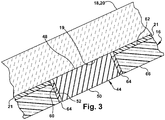
Fig. 3 is an enlarged view of a portion of the apparatus ofFig. 1 . -
Fig. 1 illustrates a system orapparatus 10 for moderating the environment around a DAS camera in accordance with an example embodiment of the present invention. Theapparatus 10 includes ahousing 12 that contains or supports a vision device 14 (Fig. 2 ), such as a CCD or CMOS camera. Theapparatus 10 also includes abracket 16 configured and dimensioned to receive and retain thehousing 12. - As shown in
Fig. 1 , thebracket 16 is attached to a window 18 of a vehicle (not shown). More particularly, thebracket 16 is attached to a windscreen or windshield 20 of an automotive vehicle (not shown). Thebracket 16 may be attached or secured to the windshield 20 via a layer of adhesive 21 (Fig. 3 ). The attachment or securement of thebracket 16 may be performed at the premises of the manufacturer of the windshield 20. Thus, when the windshield 20 is shipped or delivered to the manufacturer or assembler of the vehicle (not shown), thebracket 16 may already be attached to the windshield and ready to receive and retain thehousing 12 with thevision device 14. Thehousing 12, which contains or supports thevision device 14, may then be installed or mounted in thebracket 16 after the windshield 20 is installed in the vehicle (not shown) on the assembly line of the vehicle manufacturer or assembler. - The
housing 12 may have any construction or configuration suitable to contain or support thevision device 14 and suitable to be received and retained in thebracket 16. As shown inFigs. 1 and 2 , thehousing 12 has a generally rectangular configuration. At one end of thehousing 12 are two laterally spaced aparttabs housing 12 are two laterally spaced apartslots Fig. 1 ) of the housing to a lower surface 32 (as viewed inFig, 1 ) of the housing. Thetabs Fig. 1 ) formed at one longitudinal end of and in one piece with thebracket 16. Theslots Fig. 1 ) formed at the opposite longitudinal end of and in one piece with thebracket 16. Each of thearms 36 includes aprojection 38 that engages acorresponding projection 40 on thehousing 12. Thearms 36 are flexible and resilient so that theprojection 38 may snap over theprojection 40 and so that the arms may resiliently urge thetabs hooks 34. - As shown in
Fig. 2 , arecess 42 is formed in theupper surface 30 of thehousing 12 adjacent to theslots recess 42 is outwardly and upwardly angled in a direction away from theslots tabs vision device 14 is contained or mounted in thehousing 12 so that the vision device has a view outwardly and upwardly from a position adjacent to theslots housing 12 is mounted in thebracket 16, thevision device 14 will have an unobstructed view through the windshield 20 toward the front of the vehicle (not shown), as indicated by the arrow F inFig. 1 . - Within the
housing 12, in the space between thevision device 14 and thetabs housing 12. In operation, thevision device 14 and the electronic components will generate heat, which will need to be dissipated to avoid thermal damage to the electronic components and/or the vision device. - To facilitate dissipation of such heat, the
bracket 16 mounts or carries a thermallyconductive body 44. The thermallyconductive body 44 may be received in a passage or opening 52 that extends through thebracket 16 from afirst surface 62 to an opposedsecond surface 66 of the bracket. The upper surface of the thermally conductive body engages and presses against the windshield 20. When thehousing 12 is pressed or snapped into thebracket 16, theportion 46 of theupper surface 30 of thehousing 12 located between thevision device 14 and thetabs conductive body 44. Heat will then be conducted from thehousing 12 through the thermallyconductive body 44 into the windshield 20, where the heat can be more readily dissipated by, for example, air flow over the windshield, which has a much larger surface area for heat dissipation than the thermally conductive body, the housing or thebracket 16. The environment of thevision device 14 may thus be cooled or moderated via the vehicle windshield 20. - The thermally
conductive body 44 is made or formed of a material, such as a metal, with a thermal conductivity that is higher than the thermal conductivity of the material of which thebracket 16 is made or formed, which may be a plastic or polymer. By way of example, thebracket 16 may be formed of nylon 6/6, which has a thermal conductivity of about 0.25 watts per meter Kelvin, while the thermallyconductive body 44 may be formed of carbon steel, which has a thermal conductivity of about 43 watts per meter Kelvin. Other materials may be used to form or make thebracket 16 and the thermallyconductive body 44, as desired. The use of a plastic or polymer to make or form thebracket 16 results in a relatively strong and lightweight bracket with desirable flexibility and resilience. The use of a metal to make or form the thermallyconductive body 44 results in a member with higher thermal conductivity and also greater weight per unit volume than abracket 16 made or formed of plastic. Mounting a relatively small thermallyconductive body 44 in a relativelylarger bracket 16 provides desired thermal conductivity in a defined area without unduly increasing the total weight of the bracket and the thermally conductive body. As plastics generally have thermal conductivities less than 1.0 watt per meter Kelvin, metals generally have thermal conductivities substantially greater than 1.0 watt per meter Kelvin, and glass may have a thermal conductivity of about 1.0 watt per meter Kelvin, the thermallyconductive body 44 may be fabricated of a material have a thermal conductivity equal to or greater than 1.0 watt per meter Kelvin. - The thermally
conductive body 44 may have any convenient or desired shape, such as square or circular, with first and second opposed major side surfaces 48 and 50 (Fig. 3 ). The thermallyconductive body 44 is mounted in thebracket 16 in an orientation such that when the bracket is attached to the windshield 20, the firstmajor side surface 48 is presented toward the windshield and the opposed secondmajor side surface 50 is presented away from the windshield. When the bracket is attached to the windshield 20, the firstmajor side surface 48 of the thermallyconductive body 44 contacts and presses against aninterior side surface 19 of the windshield 20. - To help achieve a close contact between the first
major side surface 48 of the thermallyconductive body 44 and theinterior side surface 19 of the windshield 20, the thermallyconductive body 44 may be mounted or carried in thebracket 16 such that the firstmajor side surface 48 is disposed at a position or in a plane higher than or outward of the position or plane of a generally parallel adjacent portion of thefirst surface 62 of thebracket 16, as can be seen inFig. 3 . In other words, the extent to which the thermallyconductive body 44 projects or extends away from the adjacent portion of thefirst surface 62 of thebracket 16 is established or predetermined so as to ensure that the firstmajor side surface 48 will be in close contact with the windshield 20 when thebracket 16 is attached to the windshield. The difference in the relative positions of the firstmajor side surface 48 of the thermallyconductive body 44 and the adjacent portion of thefirst surface 62 of thebracket 16 helps to ensure that the first major side surface contacts theinterior side surface 19 of the windshield 20 before the adjacent portion of thefirst surface 62 of the bracket during the process of attaching or securing the bracket to the windshield. The difference in the relative positions of the firstmajor side surface 48 of the thermallyconductive body 44 and the adjacent portion of thefirst surface 62 of thebracket 16 also helps to ensure that the thickness of theadhesive layer 21 will not cause the firstmajor side surface 48 to be held away from or spaced apart from theinterior side surface 19 of the windshield 20. - To help achieve a close contact between the first
major side surface 48 of the thermallyconductive body 44 and theinterior side surface 19 of the windshield 20 while also accommodating manufacturing tolerances, the thermallyconductive body 44 may be mounted or carried in thebracket 16 using a narrow layer of anelastomeric material 64 interposed between and bonded or fixed to both the bracket and anouter periphery 60 of the thermally conductive body. Because theelastomeric material 64 is flexible, the thermallyconductive body 44 will be permitted to move to a small extent relative to thebracket 16, in a downward direction as viewed inFig. 3 , as the bracket is attached to the windshield 20. At the same time, because theelastomeric material 64 is resilient, the thermallyconductive body 44 will continue to be pressed against theinterior side surface 19 of the windshield 20 as the bracket is attached to the windshield 20. As used in this application, the word "flexible" means that a material, such as theelastomeric material 64, is capable of being flexed, which is to say capable of being turned, bowed, or twisted without breaking. As used in this application, "resilient" means that a material, such as theelastomeric material 64, is capable of returning freely to a previous position, shape or condition, which is to say capable of recovering its size and shape after deformation. - As a further aid in achieving close contact between the first
major side surface 48 of the thermallyconductive body 44 and theinterior side surface 19 of the windshield 20 to facilitate heat transfer from the thermallyconductive body 44 to the windshield 20, the firstmajor side surface 48 of the thermallyconductive body 44 and the abutting or contacting portion of theinterior side surface 19 of the windshield 20 may have complementary or substantially parallel surface contours. As depicted inFig. 3 , the firstmajor side surface 48 of the thermallyconductive body 44 and the abutting or contacting portion of theinterior side surface 19 of the windshield 20 are substantially flat. In other words, the firstmajor side surface 48 of the thermallyconductive body 44 and the abutting or contacting portion of theinterior side surface 19 of the windshield 20 have a degree of flatness or parallelism necessary to achieve effective and efficient heat transfer, subject to commercial cost constraints and manufacturing efficiency. Although substantially flat surfaces are depicted inFig. 3 , the firstmajor side surface 48 of the thermallyconductive body 44 and the abutting or contacting portion of theinterior side surface 19 of the windshield 20 may have other complementary or parallel surface contours, as desired. - As the
housing 12 is being mounted in thebracket 16, theportion 46 of theupper surface 30 of thehousing 12 located between thevision device 14 and thetabs major side surface 50 of the thermallyconductive body 44 and will press against the second major side surface. To help achieve close contact between theportion 46 of theupper surface 30 of thehousing 12 and the secondmajor side surface 50 of the thermallyconductive body 44 to facilitate heat transfer from thehousing 12 to the thermallyconductive body 44, the secondmajor side surface 50 may project or extend a small distance away from an adjacent portion of thesecond surface 66 of thebracket 16. In addition, theportion 46 of theupper surface 30 of thehousing 12 and the secondmajor side surface 50 of the thermallyconductive body 44 may have complementary or substantially parallel surface contours. As depicted inFig. 3 , theportion 46 of theupper surface 30 of thehousing 12 and the secondmajor side surface 50 of the thermallyconductive body 44 are substantially flat. In other words, theportion 46 of theupper surface 30 of thehousing 12 and the secondmajor side surface 50 of the thermallyconductive body 44 have a degree of flatness or parallelism necessary to achieve effective and efficient heat transfer, subject to commercial cost constraints and manufacturing efficiency. Although substantially flat surfaces are depicted inFig. 3 , theportion 46 of theupper surface 30 of thehousing 12 and the secondmajor side surface 50 of the thermallyconductive body 44 may have other complementary or parallel surface contours, as desired. - Further to facilitate heat transfer from the
housing 12 to the thermallyconductive body 44, an optional thermallyconductive member 68 may be mounted on or carried by theportion 46 of theupper surface 30 of thehousing 12, as shown inFig. 2 . The optional thermallyconductive member 68 may have the same characteristics as the thermallyconductive body 44 and may be mounted on or carried by thehousing 12 in the same manner as the thermallyconductive body 44 is mounted on or carried by thebracket 16. Accordingly, among other things, the thermallyconductive member 68 may be made or formed of a material, such as a metal, with a thermal conductivity that is higher than the thermal conductivity of the material of which thehousing 12 is made or formed, which may be a plastic or polymer. The thermallyconductive member 68 may be mounted on or carried by thehousing 12 such that a major side surface of the thermally conductive member is disposed at a position or in a plane higher than or outward of the position or plane of a generally parallel adjacent surface of thehousing 12. The thermallyconductive member 68 may also be mounted on or carried by thehousing 12 using a narrow layer of an elastomeric material (not shown) interposed between and bonded or fixed to both the housing and an outer periphery of the thermally conductive member. Further, a major side surface of the thermallyconductive member 68 and the abutting or contacting portion of the thermallyconductive body 44 may have complementary or substantially parallel surface contours. - Although the system or
apparatus 10 is described as being used to transfer heat from thehousing 12 to the windshield 20 of a vehicle (not shown), the apparatus may also potentially be used to transfer heat from the windshield to the housing. Such heat transfer may potentially be useful in a situation in which the vehicle (not shown) has a relatively low interior temperature, but the atmospheric environment outside of the vehicle is sunny, thus heating the windshield more quickly than the interior of the vehicle in which the apparatus is mounted. - From the above description of the invention, those skilled in the art will perceive improvements, changes and modifications. Such improvements, changes and modifications within the skill of the art are intended to be covered by the appended claims.
Claims (6)
- An apparatus for helping to manage a temperature of an environment of a driver assist camera (14) of a vehicle comprising:a housing (12) in which the driver assist camera (14) is mountable;a bracket (16) configured and dimensioned to receive and retain the housing, the bracket (16) being formed of a first material having a first thermal conductivity, the bracket when installed in a vehicle being attached to a window (20) of the vehicle; anda body (44) formed of a second material having a second thermal conductivity, the body (44) being mounted on the bracket (16) and being received in an opening (52) extending through the bracket (16) from a first surface (62) of the bracket (16) to an opposed second surface (66) of the bracket (16), the second thermal conductivity being greater than the first thermal conductivity;the housing (12) when received in the bracket (16) being in close proximity to the body (44), the body (44) when the bracket (16) is attached to the window (20) of the vehicle contacting the window (20) so as to transfer heat between the window (20) and the housing (16), thereby modifying the temperature of the environment of the driver assist camera (14).
- The apparatus of claim 1 wherein the housing (12) when received in the bracket (16) is in contact with the body (44).
- The apparatus of claim 1 wherein the second material has a thermal conductivity of at least 1 watt per meter per Kelvin.
- The apparatus of claim 1 wherein the first material is a polymer and the second material is a metal.
- The apparatus of claim 1 comprising an elastomeric material (64) interposed between the body (44) and the bracket (16) that mounts the body (44) on the bracket (16).
- The apparatus of claim 1 comprising a member (68) mounted on the housing (12), the member (68) when the housing (12) is received in the bracket (16) contacting the body (44) so as to transfer heat between the window (20) and housing via the member (68) and the body (44).
Applications Claiming Priority (1)
| Application Number | Priority Date | Filing Date | Title |
|---|---|---|---|
| US15/453,070 US10488738B2 (en) | 2017-03-08 | 2017-03-08 | Temperature management of a driver assist camera via a vehicle windshield |
Publications (2)
| Publication Number | Publication Date |
|---|---|
| EP3372452A1 EP3372452A1 (en) | 2018-09-12 |
| EP3372452B1 true EP3372452B1 (en) | 2019-09-18 |
Family
ID=61692183
Family Applications (1)
| Application Number | Title | Priority Date | Filing Date |
|---|---|---|---|
| EP18160086.7A Active EP3372452B1 (en) | 2017-03-08 | 2018-03-06 | Temperature management of a driver assist camera via a vehicle windshield |
Country Status (3)
| Country | Link |
|---|---|
| US (1) | US10488738B2 (en) |
| EP (1) | EP3372452B1 (en) |
| CN (1) | CN108569222B (en) |
Families Citing this family (2)
| Publication number | Priority date | Publication date | Assignee | Title |
|---|---|---|---|---|
| CN113260534B (en) * | 2018-12-28 | 2024-08-09 | Zf主动安全和电子美国有限公司 | Driver assistance system |
| US10981520B1 (en) | 2019-11-14 | 2021-04-20 | Zf Friedrichshafen Ag | Driver assist system for a vehicle |
Family Cites Families (13)
| Publication number | Priority date | Publication date | Assignee | Title |
|---|---|---|---|---|
| DE10237606B4 (en) * | 2002-08-16 | 2006-04-27 | Hella Kgaa Hueck & Co. | Camera arrangement for motor vehicles |
| US8256821B2 (en) * | 2004-12-15 | 2012-09-04 | Magna Donnelly Engineering Gmbh | Accessory module system for a vehicle window |
| US20070216768A1 (en) * | 2006-03-14 | 2007-09-20 | Ford Global Technologies, Llc | Device and method for outwardly looking ir camera mounted inside vehicles particularly suited for pre-crash sensing and pedestrian detection |
| DE102006059554B4 (en) * | 2006-12-16 | 2022-03-10 | Kostal Automobil Elektrik Gmbh & Co. Kg | Optoelectronic sensor device |
| US8339453B2 (en) * | 2010-07-14 | 2012-12-25 | Trw Automotive U.S. Llc | Apparatus for use in association with a vehicle |
| US20150042874A1 (en) * | 2013-08-08 | 2015-02-12 | Nidec Elesys Corporation | In-vehicle camera |
| JP6413754B2 (en) | 2014-03-10 | 2018-10-31 | 株式会社デンソー | Imaging device and in-vehicle device provided with imaging device |
| JP2016014564A (en) * | 2014-07-01 | 2016-01-28 | 株式会社リコー | Imaging unit |
| JP6052246B2 (en) * | 2014-07-10 | 2016-12-27 | トヨタ自動車株式会社 | In-vehicle camera mounting structure |
| JP6303974B2 (en) * | 2014-10-22 | 2018-04-04 | 株式会社デンソー | In-vehicle camera device and in-vehicle system |
| JP6197812B2 (en) * | 2015-03-05 | 2017-09-20 | トヨタ自動車株式会社 | In-vehicle camera mounting structure |
| JP6421691B2 (en) * | 2015-04-28 | 2018-11-14 | 株式会社デンソー | Camera device |
| JP6390512B2 (en) | 2015-05-21 | 2018-09-19 | 株式会社デンソー | In-vehicle camera device |
-
2017
- 2017-03-08 US US15/453,070 patent/US10488738B2/en active Active
-
2018
- 2018-03-06 EP EP18160086.7A patent/EP3372452B1/en active Active
- 2018-03-08 CN CN201810188713.3A patent/CN108569222B/en active Active
Non-Patent Citations (1)
| Title |
|---|
| None * |
Also Published As
| Publication number | Publication date |
|---|---|
| EP3372452A1 (en) | 2018-09-12 |
| CN108569222B (en) | 2022-03-01 |
| US20180259830A1 (en) | 2018-09-13 |
| CN108569222A (en) | 2018-09-25 |
| US10488738B2 (en) | 2019-11-26 |
Similar Documents
| Publication | Publication Date | Title |
|---|---|---|
| US10288986B2 (en) | Moderation of a driver assist camera enhancement via a vehicle windshield | |
| US20200382682A1 (en) | Camera module for vehicular vision system | |
| EP3281397B1 (en) | Camera heater for advanced driver assistance system | |
| US9854225B2 (en) | Imaging unit including a chassis and heat transfer member | |
| JP7312164B2 (en) | Lens unit and camera module | |
| US9544487B2 (en) | Camera system with image sensor contacting metallic housing via heat conducting element | |
| CN111983766A (en) | Optical lens and imaging module | |
| EP3372452B1 (en) | Temperature management of a driver assist camera via a vehicle windshield | |
| KR20170040672A (en) | Camera module and system for preventing of dew condensation in camera module | |
| JP2017118445A (en) | On-vehicle camera | |
| CN113165578B (en) | Heatable device for a vehicle-mounted image acquisition unit | |
| US11927747B2 (en) | Camera module, vehicle camera and monitoring system | |
| JP6897750B2 (en) | Imaging unit | |
| JP7541844B2 (en) | Imaging device and vehicle | |
| US11953809B2 (en) | Camera support structure and head-mounted display | |
| CN217216725U (en) | Camera device and processing system of images in vehicle cabin | |
| CN114390164A (en) | Image forming apparatus | |
| CN112789958A (en) | Heat dissipation device, heat dissipation assembly and mobile platform | |
| US20240305871A1 (en) | Imaging device | |
| US11997373B2 (en) | Camera module for a vehicle | |
| CN218886376U (en) | Camera lens with defrosting and defogging functions | |
| JP2021160563A (en) | On-vehicle device, electronic device, and mounting member or the like | |
| US20240053663A1 (en) | Image capturing unit | |
| CN117652147A (en) | Camera module |
Legal Events
| Date | Code | Title | Description |
|---|---|---|---|
| PUAI | Public reference made under article 153(3) epc to a published international application that has entered the european phase |
Free format text: ORIGINAL CODE: 0009012 |
|
| STAA | Information on the status of an ep patent application or granted ep patent |
Free format text: STATUS: THE APPLICATION HAS BEEN PUBLISHED |
|
| AK | Designated contracting states |
Kind code of ref document: A1 Designated state(s): AL AT BE BG CH CY CZ DE DK EE ES FI FR GB GR HR HU IE IS IT LI LT LU LV MC MK MT NL NO PL PT RO RS SE SI SK SM TR |
|
| AX | Request for extension of the european patent |
Extension state: BA ME |
|
| STAA | Information on the status of an ep patent application or granted ep patent |
Free format text: STATUS: REQUEST FOR EXAMINATION WAS MADE |
|
| 17P | Request for examination filed |
Effective date: 20190312 |
|
| RBV | Designated contracting states (corrected) |
Designated state(s): AL AT BE BG CH CY CZ DE DK EE ES FI FR GB GR HR HU IE IS IT LI LT LU LV MC MK MT NL NO PL PT RO RS SE SI SK SM TR |
|
| GRAP | Despatch of communication of intention to grant a patent |
Free format text: ORIGINAL CODE: EPIDOSNIGR1 |
|
| STAA | Information on the status of an ep patent application or granted ep patent |
Free format text: STATUS: GRANT OF PATENT IS INTENDED |
|
| INTG | Intention to grant announced |
Effective date: 20190426 |
|
| GRAS | Grant fee paid |
Free format text: ORIGINAL CODE: EPIDOSNIGR3 |
|
| GRAA | (expected) grant |
Free format text: ORIGINAL CODE: 0009210 |
|
| STAA | Information on the status of an ep patent application or granted ep patent |
Free format text: STATUS: THE PATENT HAS BEEN GRANTED |
|
| AK | Designated contracting states |
Kind code of ref document: B1 Designated state(s): AL AT BE BG CH CY CZ DE DK EE ES FI FR GB GR HR HU IE IS IT LI LT LU LV MC MK MT NL NO PL PT RO RS SE SI SK SM TR |
|
| REG | Reference to a national code |
Ref country code: GB Ref legal event code: FG4D |
|
| REG | Reference to a national code |
Ref country code: CH Ref legal event code: EP |
|
| REG | Reference to a national code |
Ref country code: DE Ref legal event code: R096 Ref document number: 602018000661 Country of ref document: DE |
|
| REG | Reference to a national code |
Ref country code: AT Ref legal event code: REF Ref document number: 1180899 Country of ref document: AT Kind code of ref document: T Effective date: 20191015 |
|
| REG | Reference to a national code |
Ref country code: IE Ref legal event code: FG4D |
|
| REG | Reference to a national code |
Ref country code: NL Ref legal event code: MP Effective date: 20190918 |
|
| PG25 | Lapsed in a contracting state [announced via postgrant information from national office to epo] |
Ref country code: FI Free format text: LAPSE BECAUSE OF FAILURE TO SUBMIT A TRANSLATION OF THE DESCRIPTION OR TO PAY THE FEE WITHIN THE PRESCRIBED TIME-LIMIT Effective date: 20190918 Ref country code: HR Free format text: LAPSE BECAUSE OF FAILURE TO SUBMIT A TRANSLATION OF THE DESCRIPTION OR TO PAY THE FEE WITHIN THE PRESCRIBED TIME-LIMIT Effective date: 20190918 Ref country code: LT Free format text: LAPSE BECAUSE OF FAILURE TO SUBMIT A TRANSLATION OF THE DESCRIPTION OR TO PAY THE FEE WITHIN THE PRESCRIBED TIME-LIMIT Effective date: 20190918 Ref country code: SE Free format text: LAPSE BECAUSE OF FAILURE TO SUBMIT A TRANSLATION OF THE DESCRIPTION OR TO PAY THE FEE WITHIN THE PRESCRIBED TIME-LIMIT Effective date: 20190918 Ref country code: BG Free format text: LAPSE BECAUSE OF FAILURE TO SUBMIT A TRANSLATION OF THE DESCRIPTION OR TO PAY THE FEE WITHIN THE PRESCRIBED TIME-LIMIT Effective date: 20191218 Ref country code: NO Free format text: LAPSE BECAUSE OF FAILURE TO SUBMIT A TRANSLATION OF THE DESCRIPTION OR TO PAY THE FEE WITHIN THE PRESCRIBED TIME-LIMIT Effective date: 20191218 |
|
| REG | Reference to a national code |
Ref country code: LT Ref legal event code: MG4D |
|
| PG25 | Lapsed in a contracting state [announced via postgrant information from national office to epo] |
Ref country code: AL Free format text: LAPSE BECAUSE OF FAILURE TO SUBMIT A TRANSLATION OF THE DESCRIPTION OR TO PAY THE FEE WITHIN THE PRESCRIBED TIME-LIMIT Effective date: 20190918 Ref country code: GR Free format text: LAPSE BECAUSE OF FAILURE TO SUBMIT A TRANSLATION OF THE DESCRIPTION OR TO PAY THE FEE WITHIN THE PRESCRIBED TIME-LIMIT Effective date: 20191219 Ref country code: LV Free format text: LAPSE BECAUSE OF FAILURE TO SUBMIT A TRANSLATION OF THE DESCRIPTION OR TO PAY THE FEE WITHIN THE PRESCRIBED TIME-LIMIT Effective date: 20190918 Ref country code: RS Free format text: LAPSE BECAUSE OF FAILURE TO SUBMIT A TRANSLATION OF THE DESCRIPTION OR TO PAY THE FEE WITHIN THE PRESCRIBED TIME-LIMIT Effective date: 20190918 |
|
| REG | Reference to a national code |
Ref country code: AT Ref legal event code: MK05 Ref document number: 1180899 Country of ref document: AT Kind code of ref document: T Effective date: 20190918 |
|
| PG25 | Lapsed in a contracting state [announced via postgrant information from national office to epo] |
Ref country code: EE Free format text: LAPSE BECAUSE OF FAILURE TO SUBMIT A TRANSLATION OF THE DESCRIPTION OR TO PAY THE FEE WITHIN THE PRESCRIBED TIME-LIMIT Effective date: 20190918 Ref country code: PT Free format text: LAPSE BECAUSE OF FAILURE TO SUBMIT A TRANSLATION OF THE DESCRIPTION OR TO PAY THE FEE WITHIN THE PRESCRIBED TIME-LIMIT Effective date: 20200120 Ref country code: PL Free format text: LAPSE BECAUSE OF FAILURE TO SUBMIT A TRANSLATION OF THE DESCRIPTION OR TO PAY THE FEE WITHIN THE PRESCRIBED TIME-LIMIT Effective date: 20190918 Ref country code: RO Free format text: LAPSE BECAUSE OF FAILURE TO SUBMIT A TRANSLATION OF THE DESCRIPTION OR TO PAY THE FEE WITHIN THE PRESCRIBED TIME-LIMIT Effective date: 20190918 Ref country code: IT Free format text: LAPSE BECAUSE OF FAILURE TO SUBMIT A TRANSLATION OF THE DESCRIPTION OR TO PAY THE FEE WITHIN THE PRESCRIBED TIME-LIMIT Effective date: 20190918 Ref country code: NL Free format text: LAPSE BECAUSE OF FAILURE TO SUBMIT A TRANSLATION OF THE DESCRIPTION OR TO PAY THE FEE WITHIN THE PRESCRIBED TIME-LIMIT Effective date: 20190918 Ref country code: AT Free format text: LAPSE BECAUSE OF FAILURE TO SUBMIT A TRANSLATION OF THE DESCRIPTION OR TO PAY THE FEE WITHIN THE PRESCRIBED TIME-LIMIT Effective date: 20190918 Ref country code: ES Free format text: LAPSE BECAUSE OF FAILURE TO SUBMIT A TRANSLATION OF THE DESCRIPTION OR TO PAY THE FEE WITHIN THE PRESCRIBED TIME-LIMIT Effective date: 20190918 |
|
| PG25 | Lapsed in a contracting state [announced via postgrant information from national office to epo] |
Ref country code: IS Free format text: LAPSE BECAUSE OF FAILURE TO SUBMIT A TRANSLATION OF THE DESCRIPTION OR TO PAY THE FEE WITHIN THE PRESCRIBED TIME-LIMIT Effective date: 20200224 Ref country code: SK Free format text: LAPSE BECAUSE OF FAILURE TO SUBMIT A TRANSLATION OF THE DESCRIPTION OR TO PAY THE FEE WITHIN THE PRESCRIBED TIME-LIMIT Effective date: 20190918 Ref country code: SM Free format text: LAPSE BECAUSE OF FAILURE TO SUBMIT A TRANSLATION OF THE DESCRIPTION OR TO PAY THE FEE WITHIN THE PRESCRIBED TIME-LIMIT Effective date: 20190918 Ref country code: CZ Free format text: LAPSE BECAUSE OF FAILURE TO SUBMIT A TRANSLATION OF THE DESCRIPTION OR TO PAY THE FEE WITHIN THE PRESCRIBED TIME-LIMIT Effective date: 20190918 |
|
| REG | Reference to a national code |
Ref country code: DE Ref legal event code: R097 Ref document number: 602018000661 Country of ref document: DE |
|
| PLBE | No opposition filed within time limit |
Free format text: ORIGINAL CODE: 0009261 |
|
| STAA | Information on the status of an ep patent application or granted ep patent |
Free format text: STATUS: NO OPPOSITION FILED WITHIN TIME LIMIT |
|
| PG2D | Information on lapse in contracting state deleted |
Ref country code: IS |
|
| PG25 | Lapsed in a contracting state [announced via postgrant information from national office to epo] |
Ref country code: DK Free format text: LAPSE BECAUSE OF FAILURE TO SUBMIT A TRANSLATION OF THE DESCRIPTION OR TO PAY THE FEE WITHIN THE PRESCRIBED TIME-LIMIT Effective date: 20190918 Ref country code: IS Free format text: LAPSE BECAUSE OF FAILURE TO SUBMIT A TRANSLATION OF THE DESCRIPTION OR TO PAY THE FEE WITHIN THE PRESCRIBED TIME-LIMIT Effective date: 20200119 |
|
| 26N | No opposition filed |
Effective date: 20200619 |
|
| PG25 | Lapsed in a contracting state [announced via postgrant information from national office to epo] |
Ref country code: SI Free format text: LAPSE BECAUSE OF FAILURE TO SUBMIT A TRANSLATION OF THE DESCRIPTION OR TO PAY THE FEE WITHIN THE PRESCRIBED TIME-LIMIT Effective date: 20190918 |
|
| PG25 | Lapsed in a contracting state [announced via postgrant information from national office to epo] |
Ref country code: MC Free format text: LAPSE BECAUSE OF FAILURE TO SUBMIT A TRANSLATION OF THE DESCRIPTION OR TO PAY THE FEE WITHIN THE PRESCRIBED TIME-LIMIT Effective date: 20190918 |
|
| REG | Reference to a national code |
Ref country code: BE Ref legal event code: MM Effective date: 20200331 |
|
| PG25 | Lapsed in a contracting state [announced via postgrant information from national office to epo] |
Ref country code: LU Free format text: LAPSE BECAUSE OF NON-PAYMENT OF DUE FEES Effective date: 20200306 |
|
| PG25 | Lapsed in a contracting state [announced via postgrant information from national office to epo] |
Ref country code: IE Free format text: LAPSE BECAUSE OF NON-PAYMENT OF DUE FEES Effective date: 20200306 |
|
| PG25 | Lapsed in a contracting state [announced via postgrant information from national office to epo] |
Ref country code: BE Free format text: LAPSE BECAUSE OF NON-PAYMENT OF DUE FEES Effective date: 20200331 |
|
| REG | Reference to a national code |
Ref country code: CH Ref legal event code: PL |
|
| PG25 | Lapsed in a contracting state [announced via postgrant information from national office to epo] |
Ref country code: LI Free format text: LAPSE BECAUSE OF NON-PAYMENT OF DUE FEES Effective date: 20210331 Ref country code: CH Free format text: LAPSE BECAUSE OF NON-PAYMENT OF DUE FEES Effective date: 20210331 |
|
| PG25 | Lapsed in a contracting state [announced via postgrant information from national office to epo] |
Ref country code: TR Free format text: LAPSE BECAUSE OF FAILURE TO SUBMIT A TRANSLATION OF THE DESCRIPTION OR TO PAY THE FEE WITHIN THE PRESCRIBED TIME-LIMIT Effective date: 20190918 Ref country code: MT Free format text: LAPSE BECAUSE OF FAILURE TO SUBMIT A TRANSLATION OF THE DESCRIPTION OR TO PAY THE FEE WITHIN THE PRESCRIBED TIME-LIMIT Effective date: 20190918 Ref country code: CY Free format text: LAPSE BECAUSE OF FAILURE TO SUBMIT A TRANSLATION OF THE DESCRIPTION OR TO PAY THE FEE WITHIN THE PRESCRIBED TIME-LIMIT Effective date: 20190918 |
|
| PG25 | Lapsed in a contracting state [announced via postgrant information from national office to epo] |
Ref country code: MK Free format text: LAPSE BECAUSE OF FAILURE TO SUBMIT A TRANSLATION OF THE DESCRIPTION OR TO PAY THE FEE WITHIN THE PRESCRIBED TIME-LIMIT Effective date: 20190918 |
|
| PGFP | Annual fee paid to national office [announced via postgrant information from national office to epo] |
Ref country code: FR Payment date: 20230110 Year of fee payment: 6 |
|
| PGFP | Annual fee paid to national office [announced via postgrant information from national office to epo] |
Ref country code: GB Payment date: 20230112 Year of fee payment: 6 Ref country code: DE Payment date: 20230110 Year of fee payment: 6 |
|
| P01 | Opt-out of the competence of the unified patent court (upc) registered |
Effective date: 20230628 |