EP3370934B1 - Dispositif de séparation servant à séparer des tronçons d'une bande de matériau, machine de stratification munie d'un dispositif de séparation, et procédé de séparation d'au moins un tronçon d'une bande de matériau - Google Patents
Dispositif de séparation servant à séparer des tronçons d'une bande de matériau, machine de stratification munie d'un dispositif de séparation, et procédé de séparation d'au moins un tronçon d'une bande de matériau Download PDFInfo
- Publication number
- EP3370934B1 EP3370934B1 EP16790998.5A EP16790998A EP3370934B1 EP 3370934 B1 EP3370934 B1 EP 3370934B1 EP 16790998 A EP16790998 A EP 16790998A EP 3370934 B1 EP3370934 B1 EP 3370934B1
- Authority
- EP
- European Patent Office
- Prior art keywords
- material web
- lamination
- stretching element
- laminating
- separation
- Prior art date
- Legal status (The legal status is an assumption and is not a legal conclusion. Google has not performed a legal analysis and makes no representation as to the accuracy of the status listed.)
- Active
Links
- 239000000463 material Substances 0.000 title claims description 324
- 238000010030 laminating Methods 0.000 title claims description 209
- 238000000926 separation method Methods 0.000 title claims description 140
- 238000000034 method Methods 0.000 title claims description 53
- 239000002648 laminated material Substances 0.000 claims description 51
- 230000003247 decreasing effect Effects 0.000 claims 2
- 238000003475 lamination Methods 0.000 description 242
- 238000012545 processing Methods 0.000 description 40
- 230000033001 locomotion Effects 0.000 description 29
- 239000000126 substance Substances 0.000 description 21
- 238000005520 cutting process Methods 0.000 description 20
- 230000008569 process Effects 0.000 description 20
- 239000004744 fabric Substances 0.000 description 14
- 238000001816 cooling Methods 0.000 description 11
- 230000008901 benefit Effects 0.000 description 10
- 230000005670 electromagnetic radiation Effects 0.000 description 10
- 238000002360 preparation method Methods 0.000 description 10
- 230000006698 induction Effects 0.000 description 9
- 230000008859 change Effects 0.000 description 8
- 229910052804 chromium Inorganic materials 0.000 description 8
- 239000011651 chromium Substances 0.000 description 8
- 238000005516 engineering process Methods 0.000 description 8
- 230000001133 acceleration Effects 0.000 description 7
- 238000010438 heat treatment Methods 0.000 description 7
- 210000000056 organ Anatomy 0.000 description 6
- 238000003825 pressing Methods 0.000 description 6
- 230000005540 biological transmission Effects 0.000 description 5
- 238000004519 manufacturing process Methods 0.000 description 5
- 239000000123 paper Substances 0.000 description 5
- 230000001105 regulatory effect Effects 0.000 description 5
- 239000007779 soft material Substances 0.000 description 5
- 239000002699 waste material Substances 0.000 description 5
- VYZAMTAEIAYCRO-UHFFFAOYSA-N Chromium Chemical compound [Cr] VYZAMTAEIAYCRO-UHFFFAOYSA-N 0.000 description 4
- ZOKXTWBITQBERF-UHFFFAOYSA-N Molybdenum Chemical compound [Mo] ZOKXTWBITQBERF-UHFFFAOYSA-N 0.000 description 4
- 229910000831 Steel Inorganic materials 0.000 description 4
- -1 WC / Co Inorganic materials 0.000 description 4
- 239000000919 ceramic Substances 0.000 description 4
- VNNRSPGTAMTISX-UHFFFAOYSA-N chromium nickel Chemical compound [Cr].[Ni] VNNRSPGTAMTISX-UHFFFAOYSA-N 0.000 description 4
- 238000005304 joining Methods 0.000 description 4
- 238000003698 laser cutting Methods 0.000 description 4
- 229910001092 metal group alloy Inorganic materials 0.000 description 4
- 229910052750 molybdenum Inorganic materials 0.000 description 4
- 239000011733 molybdenum Substances 0.000 description 4
- 229910001120 nichrome Inorganic materials 0.000 description 4
- 239000010959 steel Substances 0.000 description 4
- 230000006978 adaptation Effects 0.000 description 3
- 230000033228 biological regulation Effects 0.000 description 3
- 238000012544 monitoring process Methods 0.000 description 3
- 230000003287 optical effect Effects 0.000 description 3
- 238000007639 printing Methods 0.000 description 3
- 230000009467 reduction Effects 0.000 description 3
- 238000007751 thermal spraying Methods 0.000 description 3
- 239000000853 adhesive Substances 0.000 description 2
- 238000007664 blowing Methods 0.000 description 2
- 239000011111 cardboard Substances 0.000 description 2
- 238000006073 displacement reaction Methods 0.000 description 2
- 230000002093 peripheral effect Effects 0.000 description 2
- 238000012549 training Methods 0.000 description 2
- 238000012546 transfer Methods 0.000 description 2
- OKTJSMMVPCPJKN-UHFFFAOYSA-N Carbon Chemical compound [C] OKTJSMMVPCPJKN-UHFFFAOYSA-N 0.000 description 1
- 229920000742 Cotton Polymers 0.000 description 1
- 230000009471 action Effects 0.000 description 1
- 230000001070 adhesive effect Effects 0.000 description 1
- 230000015572 biosynthetic process Effects 0.000 description 1
- 229910052799 carbon Inorganic materials 0.000 description 1
- 239000003795 chemical substances by application Substances 0.000 description 1
- 150000001875 compounds Chemical class 0.000 description 1
- 238000012790 confirmation Methods 0.000 description 1
- 239000000470 constituent Substances 0.000 description 1
- 238000010276 construction Methods 0.000 description 1
- 238000000151 deposition Methods 0.000 description 1
- 238000013461 design Methods 0.000 description 1
- 238000001514 detection method Methods 0.000 description 1
- 238000007599 discharging Methods 0.000 description 1
- 230000000694 effects Effects 0.000 description 1
- 238000004049 embossing Methods 0.000 description 1
- 238000011156 evaluation Methods 0.000 description 1
- 238000007689 inspection Methods 0.000 description 1
- 230000004446 light reflex Effects 0.000 description 1
- 238000005259 measurement Methods 0.000 description 1
- 230000007246 mechanism Effects 0.000 description 1
- 239000011087 paperboard Substances 0.000 description 1
- 230000000149 penetrating effect Effects 0.000 description 1
- 239000004033 plastic Substances 0.000 description 1
- 238000004080 punching Methods 0.000 description 1
- 230000004044 response Effects 0.000 description 1
- 230000000284 resting effect Effects 0.000 description 1
- 239000007921 spray Substances 0.000 description 1
- 238000003892 spreading Methods 0.000 description 1
- 230000007480 spreading Effects 0.000 description 1
- 239000000758 substrate Substances 0.000 description 1
- 239000004753 textile Substances 0.000 description 1
- 230000007704 transition Effects 0.000 description 1
- 238000011144 upstream manufacturing Methods 0.000 description 1
Images


Classifications
-
- B—PERFORMING OPERATIONS; TRANSPORTING
- B32—LAYERED PRODUCTS
- B32B—LAYERED PRODUCTS, i.e. PRODUCTS BUILT-UP OF STRATA OF FLAT OR NON-FLAT, e.g. CELLULAR OR HONEYCOMB, FORM
- B32B37/00—Methods or apparatus for laminating, e.g. by curing or by ultrasonic bonding
- B32B37/14—Methods or apparatus for laminating, e.g. by curing or by ultrasonic bonding characterised by the properties of the layers
- B32B37/16—Methods or apparatus for laminating, e.g. by curing or by ultrasonic bonding characterised by the properties of the layers with all layers existing as coherent layers before laminating
- B32B37/22—Methods or apparatus for laminating, e.g. by curing or by ultrasonic bonding characterised by the properties of the layers with all layers existing as coherent layers before laminating involving the assembly of both discrete and continuous layers
-
- B—PERFORMING OPERATIONS; TRANSPORTING
- B26—HAND CUTTING TOOLS; CUTTING; SEVERING
- B26D—CUTTING; DETAILS COMMON TO MACHINES FOR PERFORATING, PUNCHING, CUTTING-OUT, STAMPING-OUT OR SEVERING
- B26D1/00—Cutting through work characterised by the nature or movement of the cutting member or particular materials not otherwise provided for; Apparatus or machines therefor; Cutting members therefor
- B26D1/01—Cutting through work characterised by the nature or movement of the cutting member or particular materials not otherwise provided for; Apparatus or machines therefor; Cutting members therefor involving a cutting member which does not travel with the work
- B26D1/12—Cutting through work characterised by the nature or movement of the cutting member or particular materials not otherwise provided for; Apparatus or machines therefor; Cutting members therefor involving a cutting member which does not travel with the work having a cutting member moving about an axis
- B26D1/25—Cutting through work characterised by the nature or movement of the cutting member or particular materials not otherwise provided for; Apparatus or machines therefor; Cutting members therefor involving a cutting member which does not travel with the work having a cutting member moving about an axis with a non-circular cutting member
- B26D1/34—Cutting through work characterised by the nature or movement of the cutting member or particular materials not otherwise provided for; Apparatus or machines therefor; Cutting members therefor involving a cutting member which does not travel with the work having a cutting member moving about an axis with a non-circular cutting member moving about an axis parallel to the line of cut
- B26D1/40—Cutting through work characterised by the nature or movement of the cutting member or particular materials not otherwise provided for; Apparatus or machines therefor; Cutting members therefor involving a cutting member which does not travel with the work having a cutting member moving about an axis with a non-circular cutting member moving about an axis parallel to the line of cut and coacting with a rotary member
- B26D1/405—Cutting through work characterised by the nature or movement of the cutting member or particular materials not otherwise provided for; Apparatus or machines therefor; Cutting members therefor involving a cutting member which does not travel with the work having a cutting member moving about an axis with a non-circular cutting member moving about an axis parallel to the line of cut and coacting with a rotary member for thin material, e.g. for sheets, strips or the like
-
- B—PERFORMING OPERATIONS; TRANSPORTING
- B26—HAND CUTTING TOOLS; CUTTING; SEVERING
- B26D—CUTTING; DETAILS COMMON TO MACHINES FOR PERFORATING, PUNCHING, CUTTING-OUT, STAMPING-OUT OR SEVERING
- B26D7/00—Details of apparatus for cutting, cutting-out, stamping-out, punching, perforating, or severing by means other than cutting
- B26D7/08—Means for treating work or cutting member to facilitate cutting
- B26D7/14—Means for treating work or cutting member to facilitate cutting by tensioning the work
-
- B—PERFORMING OPERATIONS; TRANSPORTING
- B26—HAND CUTTING TOOLS; CUTTING; SEVERING
- B26D—CUTTING; DETAILS COMMON TO MACHINES FOR PERFORATING, PUNCHING, CUTTING-OUT, STAMPING-OUT OR SEVERING
- B26D7/00—Details of apparatus for cutting, cutting-out, stamping-out, punching, perforating, or severing by means other than cutting
- B26D7/18—Means for removing cut-out material or waste
- B26D7/1845—Means for removing cut-out material or waste by non mechanical means
- B26D7/1854—Means for removing cut-out material or waste by non mechanical means by air under pressure
-
- B—PERFORMING OPERATIONS; TRANSPORTING
- B26—HAND CUTTING TOOLS; CUTTING; SEVERING
- B26F—PERFORATING; PUNCHING; CUTTING-OUT; STAMPING-OUT; SEVERING BY MEANS OTHER THAN CUTTING
- B26F3/00—Severing by means other than cutting; Apparatus therefor
- B26F3/002—Precutting and tensioning or breaking
-
- B—PERFORMING OPERATIONS; TRANSPORTING
- B26—HAND CUTTING TOOLS; CUTTING; SEVERING
- B26F—PERFORATING; PUNCHING; CUTTING-OUT; STAMPING-OUT; SEVERING BY MEANS OTHER THAN CUTTING
- B26F3/00—Severing by means other than cutting; Apparatus therefor
- B26F3/06—Severing by using heat
-
- B—PERFORMING OPERATIONS; TRANSPORTING
- B32—LAYERED PRODUCTS
- B32B—LAYERED PRODUCTS, i.e. PRODUCTS BUILT-UP OF STRATA OF FLAT OR NON-FLAT, e.g. CELLULAR OR HONEYCOMB, FORM
- B32B3/00—Layered products comprising a layer with external or internal discontinuities or unevennesses, or a layer of non-planar shape; Layered products comprising a layer having particular features of form
- B32B3/10—Layered products comprising a layer with external or internal discontinuities or unevennesses, or a layer of non-planar shape; Layered products comprising a layer having particular features of form characterised by a discontinuous layer, i.e. formed of separate pieces of material
- B32B3/18—Layered products comprising a layer with external or internal discontinuities or unevennesses, or a layer of non-planar shape; Layered products comprising a layer having particular features of form characterised by a discontinuous layer, i.e. formed of separate pieces of material characterised by an internal layer formed of separate pieces of material which are juxtaposed side-by-side
-
- B—PERFORMING OPERATIONS; TRANSPORTING
- B32—LAYERED PRODUCTS
- B32B—LAYERED PRODUCTS, i.e. PRODUCTS BUILT-UP OF STRATA OF FLAT OR NON-FLAT, e.g. CELLULAR OR HONEYCOMB, FORM
- B32B33/00—Layered products characterised by particular properties or particular surface features, e.g. particular surface coatings; Layered products designed for particular purposes not covered by another single class
-
- B—PERFORMING OPERATIONS; TRANSPORTING
- B32—LAYERED PRODUCTS
- B32B—LAYERED PRODUCTS, i.e. PRODUCTS BUILT-UP OF STRATA OF FLAT OR NON-FLAT, e.g. CELLULAR OR HONEYCOMB, FORM
- B32B37/00—Methods or apparatus for laminating, e.g. by curing or by ultrasonic bonding
- B32B37/0046—Methods or apparatus for laminating, e.g. by curing or by ultrasonic bonding characterised by constructional aspects of the apparatus
- B32B37/0053—Constructional details of laminating machines comprising rollers; Constructional features of the rollers
-
- B—PERFORMING OPERATIONS; TRANSPORTING
- B32—LAYERED PRODUCTS
- B32B—LAYERED PRODUCTS, i.e. PRODUCTS BUILT-UP OF STRATA OF FLAT OR NON-FLAT, e.g. CELLULAR OR HONEYCOMB, FORM
- B32B38/00—Ancillary operations in connection with laminating processes
- B32B38/0004—Cutting, tearing or severing, e.g. bursting; Cutter details
-
- B—PERFORMING OPERATIONS; TRANSPORTING
- B32—LAYERED PRODUCTS
- B32B—LAYERED PRODUCTS, i.e. PRODUCTS BUILT-UP OF STRATA OF FLAT OR NON-FLAT, e.g. CELLULAR OR HONEYCOMB, FORM
- B32B38/00—Ancillary operations in connection with laminating processes
- B32B38/06—Embossing
-
- B—PERFORMING OPERATIONS; TRANSPORTING
- B32—LAYERED PRODUCTS
- B32B—LAYERED PRODUCTS, i.e. PRODUCTS BUILT-UP OF STRATA OF FLAT OR NON-FLAT, e.g. CELLULAR OR HONEYCOMB, FORM
- B32B38/00—Ancillary operations in connection with laminating processes
- B32B38/14—Printing or colouring
- B32B38/145—Printing
-
- B—PERFORMING OPERATIONS; TRANSPORTING
- B65—CONVEYING; PACKING; STORING; HANDLING THIN OR FILAMENTARY MATERIAL
- B65H—HANDLING THIN OR FILAMENTARY MATERIAL, e.g. SHEETS, WEBS, CABLES
- B65H1/00—Supports or magazines for piles from which articles are to be separated
- B65H1/26—Supports or magazines for piles from which articles are to be separated with auxiliary supports to facilitate introduction or renewal of the pile
- B65H1/263—Auxiliary supports for keeping the pile in the separation process during introduction of a new pile
-
- B—PERFORMING OPERATIONS; TRANSPORTING
- B65—CONVEYING; PACKING; STORING; HANDLING THIN OR FILAMENTARY MATERIAL
- B65H—HANDLING THIN OR FILAMENTARY MATERIAL, e.g. SHEETS, WEBS, CABLES
- B65H1/00—Supports or magazines for piles from which articles are to be separated
- B65H1/30—Supports or magazines for piles from which articles are to be separated with means for replenishing the pile during continuous separation of articles therefrom
-
- B—PERFORMING OPERATIONS; TRANSPORTING
- B65—CONVEYING; PACKING; STORING; HANDLING THIN OR FILAMENTARY MATERIAL
- B65H—HANDLING THIN OR FILAMENTARY MATERIAL, e.g. SHEETS, WEBS, CABLES
- B65H11/00—Feed tables
- B65H11/002—Feed tables incorporating transport belts
- B65H11/005—Suction belts
-
- B—PERFORMING OPERATIONS; TRANSPORTING
- B65—CONVEYING; PACKING; STORING; HANDLING THIN OR FILAMENTARY MATERIAL
- B65H—HANDLING THIN OR FILAMENTARY MATERIAL, e.g. SHEETS, WEBS, CABLES
- B65H11/00—Feed tables
- B65H11/02—Feed tables angularly adjustable in plane of articles
-
- B—PERFORMING OPERATIONS; TRANSPORTING
- B65—CONVEYING; PACKING; STORING; HANDLING THIN OR FILAMENTARY MATERIAL
- B65H—HANDLING THIN OR FILAMENTARY MATERIAL, e.g. SHEETS, WEBS, CABLES
- B65H3/00—Separating articles from piles
- B65H3/08—Separating articles from piles using pneumatic force
- B65H3/0808—Suction grippers
- B65H3/0816—Suction grippers separating from the top of pile
-
- B—PERFORMING OPERATIONS; TRANSPORTING
- B65—CONVEYING; PACKING; STORING; HANDLING THIN OR FILAMENTARY MATERIAL
- B65H—HANDLING THIN OR FILAMENTARY MATERIAL, e.g. SHEETS, WEBS, CABLES
- B65H35/00—Delivering articles from cutting or line-perforating machines; Article or web delivery apparatus incorporating cutting or line-perforating devices, e.g. adhesive tape dispensers
- B65H35/04—Delivering articles from cutting or line-perforating machines; Article or web delivery apparatus incorporating cutting or line-perforating devices, e.g. adhesive tape dispensers from or with transverse cutters or perforators
-
- B—PERFORMING OPERATIONS; TRANSPORTING
- B26—HAND CUTTING TOOLS; CUTTING; SEVERING
- B26D—CUTTING; DETAILS COMMON TO MACHINES FOR PERFORATING, PUNCHING, CUTTING-OUT, STAMPING-OUT OR SEVERING
- B26D1/00—Cutting through work characterised by the nature or movement of the cutting member or particular materials not otherwise provided for; Apparatus or machines therefor; Cutting members therefor
- B26D1/0006—Cutting members therefor
- B26D2001/0053—Cutting members therefor having a special cutting edge section or blade section
-
- B—PERFORMING OPERATIONS; TRANSPORTING
- B26—HAND CUTTING TOOLS; CUTTING; SEVERING
- B26D—CUTTING; DETAILS COMMON TO MACHINES FOR PERFORATING, PUNCHING, CUTTING-OUT, STAMPING-OUT OR SEVERING
- B26D1/00—Cutting through work characterised by the nature or movement of the cutting member or particular materials not otherwise provided for; Apparatus or machines therefor; Cutting members therefor
- B26D1/0006—Cutting members therefor
- B26D2001/0093—Cutting members therefor circular cutting discs with a radiussed blunt cutting edge
-
- B—PERFORMING OPERATIONS; TRANSPORTING
- B26—HAND CUTTING TOOLS; CUTTING; SEVERING
- B26F—PERFORATING; PUNCHING; CUTTING-OUT; STAMPING-OUT; SEVERING BY MEANS OTHER THAN CUTTING
- B26F3/00—Severing by means other than cutting; Apparatus therefor
-
- B—PERFORMING OPERATIONS; TRANSPORTING
- B26—HAND CUTTING TOOLS; CUTTING; SEVERING
- B26F—PERFORATING; PUNCHING; CUTTING-OUT; STAMPING-OUT; SEVERING BY MEANS OTHER THAN CUTTING
- B26F3/00—Severing by means other than cutting; Apparatus therefor
- B26F3/02—Tearing
-
- B—PERFORMING OPERATIONS; TRANSPORTING
- B32—LAYERED PRODUCTS
- B32B—LAYERED PRODUCTS, i.e. PRODUCTS BUILT-UP OF STRATA OF FLAT OR NON-FLAT, e.g. CELLULAR OR HONEYCOMB, FORM
- B32B41/00—Arrangements for controlling or monitoring lamination processes; Safety arrangements
- B32B2041/04—Detecting wrong registration, misalignment, deviation, failure
-
- B—PERFORMING OPERATIONS; TRANSPORTING
- B32—LAYERED PRODUCTS
- B32B—LAYERED PRODUCTS, i.e. PRODUCTS BUILT-UP OF STRATA OF FLAT OR NON-FLAT, e.g. CELLULAR OR HONEYCOMB, FORM
- B32B2309/00—Parameters for the laminating or treatment process; Apparatus details
- B32B2309/08—Dimensions, e.g. volume
- B32B2309/10—Dimensions, e.g. volume linear, e.g. length, distance, width
- B32B2309/105—Thickness
-
- B—PERFORMING OPERATIONS; TRANSPORTING
- B32—LAYERED PRODUCTS
- B32B—LAYERED PRODUCTS, i.e. PRODUCTS BUILT-UP OF STRATA OF FLAT OR NON-FLAT, e.g. CELLULAR OR HONEYCOMB, FORM
- B32B2309/00—Parameters for the laminating or treatment process; Apparatus details
- B32B2309/14—Velocity, e.g. feed speeds
-
- B—PERFORMING OPERATIONS; TRANSPORTING
- B32—LAYERED PRODUCTS
- B32B—LAYERED PRODUCTS, i.e. PRODUCTS BUILT-UP OF STRATA OF FLAT OR NON-FLAT, e.g. CELLULAR OR HONEYCOMB, FORM
- B32B2309/00—Parameters for the laminating or treatment process; Apparatus details
- B32B2309/70—Automated, e.g. using a computer or microcomputer
- B32B2309/72—For measuring or regulating, e.g. systems with feedback loops
-
- B—PERFORMING OPERATIONS; TRANSPORTING
- B32—LAYERED PRODUCTS
- B32B—LAYERED PRODUCTS, i.e. PRODUCTS BUILT-UP OF STRATA OF FLAT OR NON-FLAT, e.g. CELLULAR OR HONEYCOMB, FORM
- B32B2429/00—Carriers for sound or information
-
- B—PERFORMING OPERATIONS; TRANSPORTING
- B32—LAYERED PRODUCTS
- B32B—LAYERED PRODUCTS, i.e. PRODUCTS BUILT-UP OF STRATA OF FLAT OR NON-FLAT, e.g. CELLULAR OR HONEYCOMB, FORM
- B32B37/00—Methods or apparatus for laminating, e.g. by curing or by ultrasonic bonding
- B32B37/04—Methods or apparatus for laminating, e.g. by curing or by ultrasonic bonding characterised by the partial melting of at least one layer
-
- B—PERFORMING OPERATIONS; TRANSPORTING
- B32—LAYERED PRODUCTS
- B32B—LAYERED PRODUCTS, i.e. PRODUCTS BUILT-UP OF STRATA OF FLAT OR NON-FLAT, e.g. CELLULAR OR HONEYCOMB, FORM
- B32B37/00—Methods or apparatus for laminating, e.g. by curing or by ultrasonic bonding
- B32B37/10—Methods or apparatus for laminating, e.g. by curing or by ultrasonic bonding characterised by the pressing technique, e.g. using action of vacuum or fluid pressure
-
- B—PERFORMING OPERATIONS; TRANSPORTING
- B32—LAYERED PRODUCTS
- B32B—LAYERED PRODUCTS, i.e. PRODUCTS BUILT-UP OF STRATA OF FLAT OR NON-FLAT, e.g. CELLULAR OR HONEYCOMB, FORM
- B32B37/00—Methods or apparatus for laminating, e.g. by curing or by ultrasonic bonding
- B32B37/12—Methods or apparatus for laminating, e.g. by curing or by ultrasonic bonding characterised by using adhesives
- B32B37/1207—Heat-activated adhesive
-
- B—PERFORMING OPERATIONS; TRANSPORTING
- B32—LAYERED PRODUCTS
- B32B—LAYERED PRODUCTS, i.e. PRODUCTS BUILT-UP OF STRATA OF FLAT OR NON-FLAT, e.g. CELLULAR OR HONEYCOMB, FORM
- B32B38/00—Ancillary operations in connection with laminating processes
-
- B—PERFORMING OPERATIONS; TRANSPORTING
- B32—LAYERED PRODUCTS
- B32B—LAYERED PRODUCTS, i.e. PRODUCTS BUILT-UP OF STRATA OF FLAT OR NON-FLAT, e.g. CELLULAR OR HONEYCOMB, FORM
- B32B38/00—Ancillary operations in connection with laminating processes
- B32B38/18—Handling of layers or the laminate
- B32B38/1808—Handling of layers or the laminate characterised by the laying up of the layers
-
- B—PERFORMING OPERATIONS; TRANSPORTING
- B32—LAYERED PRODUCTS
- B32B—LAYERED PRODUCTS, i.e. PRODUCTS BUILT-UP OF STRATA OF FLAT OR NON-FLAT, e.g. CELLULAR OR HONEYCOMB, FORM
- B32B38/00—Ancillary operations in connection with laminating processes
- B32B38/18—Handling of layers or the laminate
- B32B38/1825—Handling of layers or the laminate characterised by the control or constructional features of devices for tensioning, stretching or registration
- B32B38/1833—Positioning, e.g. registration or centering
- B32B38/1841—Positioning, e.g. registration or centering during laying up
-
- B—PERFORMING OPERATIONS; TRANSPORTING
- B32—LAYERED PRODUCTS
- B32B—LAYERED PRODUCTS, i.e. PRODUCTS BUILT-UP OF STRATA OF FLAT OR NON-FLAT, e.g. CELLULAR OR HONEYCOMB, FORM
- B32B38/00—Ancillary operations in connection with laminating processes
- B32B38/18—Handling of layers or the laminate
- B32B38/1858—Handling of layers or the laminate using vacuum
-
- B—PERFORMING OPERATIONS; TRANSPORTING
- B32—LAYERED PRODUCTS
- B32B—LAYERED PRODUCTS, i.e. PRODUCTS BUILT-UP OF STRATA OF FLAT OR NON-FLAT, e.g. CELLULAR OR HONEYCOMB, FORM
- B32B38/00—Ancillary operations in connection with laminating processes
- B32B38/18—Handling of layers or the laminate
- B32B38/1875—Tensioning
-
- B—PERFORMING OPERATIONS; TRANSPORTING
- B32—LAYERED PRODUCTS
- B32B—LAYERED PRODUCTS, i.e. PRODUCTS BUILT-UP OF STRATA OF FLAT OR NON-FLAT, e.g. CELLULAR OR HONEYCOMB, FORM
- B32B41/00—Arrangements for controlling or monitoring lamination processes; Safety arrangements
-
- B—PERFORMING OPERATIONS; TRANSPORTING
- B42—BOOKBINDING; ALBUMS; FILES; SPECIAL PRINTED MATTER
- B42D—BOOKS; BOOK COVERS; LOOSE LEAVES; PRINTED MATTER CHARACTERISED BY IDENTIFICATION OR SECURITY FEATURES; PRINTED MATTER OF SPECIAL FORMAT OR STYLE NOT OTHERWISE PROVIDED FOR; DEVICES FOR USE THEREWITH AND NOT OTHERWISE PROVIDED FOR; MOVABLE-STRIP WRITING OR READING APPARATUS
- B42D25/00—Information-bearing cards or sheet-like structures characterised by identification or security features; Manufacture thereof
- B42D25/20—Information-bearing cards or sheet-like structures characterised by identification or security features; Manufacture thereof characterised by a particular use or purpose
- B42D25/29—Securities; Bank notes
-
- B—PERFORMING OPERATIONS; TRANSPORTING
- B42—BOOKBINDING; ALBUMS; FILES; SPECIAL PRINTED MATTER
- B42D—BOOKS; BOOK COVERS; LOOSE LEAVES; PRINTED MATTER CHARACTERISED BY IDENTIFICATION OR SECURITY FEATURES; PRINTED MATTER OF SPECIAL FORMAT OR STYLE NOT OTHERWISE PROVIDED FOR; DEVICES FOR USE THEREWITH AND NOT OTHERWISE PROVIDED FOR; MOVABLE-STRIP WRITING OR READING APPARATUS
- B42D25/00—Information-bearing cards or sheet-like structures characterised by identification or security features; Manufacture thereof
- B42D25/40—Manufacture
- B42D25/45—Associating two or more layers
-
- B—PERFORMING OPERATIONS; TRANSPORTING
- B65—CONVEYING; PACKING; STORING; HANDLING THIN OR FILAMENTARY MATERIAL
- B65H—HANDLING THIN OR FILAMENTARY MATERIAL, e.g. SHEETS, WEBS, CABLES
- B65H11/00—Feed tables
- B65H11/002—Feed tables incorporating transport belts
-
- B—PERFORMING OPERATIONS; TRANSPORTING
- B65—CONVEYING; PACKING; STORING; HANDLING THIN OR FILAMENTARY MATERIAL
- B65H—HANDLING THIN OR FILAMENTARY MATERIAL, e.g. SHEETS, WEBS, CABLES
- B65H2301/00—Handling processes for sheets or webs
- B65H2301/50—Auxiliary process performed during handling process
- B65H2301/51—Modifying a characteristic of handled material
- B65H2301/512—Changing form of handled material
- B65H2301/5124—Stretching; Tentering
-
- B—PERFORMING OPERATIONS; TRANSPORTING
- B65—CONVEYING; PACKING; STORING; HANDLING THIN OR FILAMENTARY MATERIAL
- B65H—HANDLING THIN OR FILAMENTARY MATERIAL, e.g. SHEETS, WEBS, CABLES
- B65H2301/00—Handling processes for sheets or webs
- B65H2301/50—Auxiliary process performed during handling process
- B65H2301/51—Modifying a characteristic of handled material
- B65H2301/515—Cutting handled material
- B65H2301/5151—Cutting handled material transversally to feeding direction
- B65H2301/51514—Breaking; Bursting; Tearing, i.e. cutting without cutting member
-
- B—PERFORMING OPERATIONS; TRANSPORTING
- B65—CONVEYING; PACKING; STORING; HANDLING THIN OR FILAMENTARY MATERIAL
- B65H—HANDLING THIN OR FILAMENTARY MATERIAL, e.g. SHEETS, WEBS, CABLES
- B65H2403/00—Power transmission; Driving means
- B65H2403/90—Machine drive
- B65H2403/94—Other features of machine drive
- B65H2403/943—Electronic shaft arrangement
-
- B—PERFORMING OPERATIONS; TRANSPORTING
- B65—CONVEYING; PACKING; STORING; HANDLING THIN OR FILAMENTARY MATERIAL
- B65H—HANDLING THIN OR FILAMENTARY MATERIAL, e.g. SHEETS, WEBS, CABLES
- B65H2404/00—Parts for transporting or guiding the handled material
- B65H2404/20—Belts
- B65H2404/26—Particular arrangement of belt, or belts
- B65H2404/261—Arrangement of belts, or belt(s) / roller(s) facing each other for forming a transport nip
- B65H2404/2613—Means for changing the transport path, e.g. deforming, lengthening
-
- B—PERFORMING OPERATIONS; TRANSPORTING
- B65—CONVEYING; PACKING; STORING; HANDLING THIN OR FILAMENTARY MATERIAL
- B65H—HANDLING THIN OR FILAMENTARY MATERIAL, e.g. SHEETS, WEBS, CABLES
- B65H2801/00—Application field
- B65H2801/03—Image reproduction devices
- B65H2801/21—Industrial-size printers, e.g. rotary printing press
-
- B—PERFORMING OPERATIONS; TRANSPORTING
- B65—CONVEYING; PACKING; STORING; HANDLING THIN OR FILAMENTARY MATERIAL
- B65H—HANDLING THIN OR FILAMENTARY MATERIAL, e.g. SHEETS, WEBS, CABLES
- B65H35/00—Delivering articles from cutting or line-perforating machines; Article or web delivery apparatus incorporating cutting or line-perforating devices, e.g. adhesive tape dispensers
- B65H35/10—Delivering articles from cutting or line-perforating machines; Article or web delivery apparatus incorporating cutting or line-perforating devices, e.g. adhesive tape dispensers from or with devices for breaking partially-cut or perforated webs, e.g. bursters
Definitions
- the invention relates to a separating device for separating sections of a material web and a lamination machine with a separating device and a method for laminating sheets of a material web and for separating at least a portion of a material web.
- a device in which the individual sheets are arranged scaled and provided together with an additional layer.
- a device By the DE 697 33 501 T2 a device is known by means of a material web is separated at perforated sections into sections. In this case, rods are moved linearly or by pivoting movements in a plane whose surface normal corresponds to the transport direction of the material web. The rods thus move only orthogonal to the material web.
- the DE 692 03 913 T2 shows a separating device for separating perforated paper, wherein the paper is held by friction on a lateral surface of a roller.
- the DE 20 2005 021 655 U1 and the DE 197 31 364 A1 each show a cutting device for cutting paper webs.
- the DE 10 2009 058 334 A1 shows a lamination machine with separator.
- WO 2008/061379 A1 discloses a laminating machine which is modular in construction and has a laminating lamination material source.
- EP 1 764 329 A2 By the EP 1 764 329 A2 is disclosed a processing machine in which the printing stock unwound from a roll and cut into sheets and then processed, for example, laminated. To unwind the printing material, a reel changer can be arranged.
- a laminating apparatus for laminating hollow bodies by lamination is known.
- a web tension is regulated by means of a plurality of sensors.
- a control is provided for the edge, with the edge being monitored.
- a lamination apparatus for laminating a web in which a web tension of the lamination material is adjusted by means of a dancer roller.
- DE 10 2010 037 592 A1 is a laminating machine with sheet feeder known. It is disclosed to either separate the sheets or to arrange them scaled. Depending on this, a corresponding material web is then generated.
- EP 2 383 117 A1 is a laminating machine with sheet feeder known. It is disclosed to arrange the bows either bumped or scaly. Depending on this, a corresponding material web is then generated.
- EP 0 586 642 B1 is a laminating machine with sheet feeder known. It is disclosed to either separate the bows or to place them in shingles or shingles. Depending on this, a corresponding material web is then generated.
- a laminating machine for laminating sheet material is known. It is disclosed to create from individual sheets by means of a sheet-like laminating a laminated material web, which then generates by extending over its entire width separation individual sheets.
- a separation device for paper in which a separating element is lowered from above onto a material web and is inclined, so that a separation of the material web begins on one side and progresses across the material web until the material web is separated. All movements of the separating element take place in a vertical plane which runs transversely to the transport direction of the material web. The separator is tilted several times.
- a separation device in which an expansion element is rotatable about an axis that is parallel to an axial direction.
- a web can be clamped and then stretched by means of the expansion element until it is torn off.
- the clamping points are opened periodically.
- the knife is arranged rotatably about an axis and the counter-holder and Absenk adopteden by means of which a web can be pressed against the knife. Then, a straight line connection of the backstays and the Absenk adopteden cuts the knife and the web is sufficiently stretched to be cut.
- WO 2013/072078 A1 is a method for the production of solar panels known.
- a film is held by negative pressure and then provided by a punching operation with holes and then laminated together with other layers.
- the film itself may already consist of several laminated layers.
- the invention has for its object to provide a separation device for separating sections of a web and a lamination machine with separator and a method for laminating sheets of a web and for separating at least a portion of a web.
- One advantage is in particular that sections of a material web can be separated in a particularly simple, precise and fast manner without incurring waste in a running operation, which would increase the risk of disruption of the processing machine.
- the precision is preferably supported by two clamping devices and optionally a single orientation of sheets.
- An advantage for example, is that a particularly fast and low-interference lamination operation is made possible. This is achieved, for example, by web-shaped lamination material and more preferably by roll changers for unwinding the lamination material.
- start-up of a lamination operation is simplified when a lamination-type disposer is disposed, for example, because it can easily and quickly start production without removing lamination material by hand from a difficult-to-reach area.
- One advantage for example, is that a particularly high degree of precision in the application of the laminating substance can be achieved. This is achieved for example by Brukantenausrichter and / or a web tension control in the supply of the lamination.
- a particularly precise alignment of sheets to be laminated takes place, for example, by singling and / or aligning the sheets and / or scaly arrangement of the sheets relative to each other.
- One advantage for example, is that lamination of sheets can be particularly precise and that the sheets or sections are not damaged in the process, for example by attacking knives or incomplete lamination.
- An advantage is, for example, if at least one separation sensor device is arranged, because then a faulty separation of a section of a material web can be reacted, for example with a stop of the separation device and / or the laminating machine. In this way, waste can be avoided and a risk of damage to the separator and / or the laminating machine can be reduced.
- An advantage is, for example, if at least one lamination agent is arranged for lamination. Then a readiness for use of the laminating machine can be produced particularly quickly and precisely, for example after a restart or after a brief interruption of a production. This facilitates handling, in particular also when laminating the material on both sides.
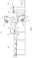
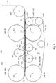
- a processing machine 01 preferably has at least one separating device 400.
- the processing machine 01 is preferably designed as a laminating machine 01.
- the processing machine 01 is in particular a processing machine 01 for flat material 02; 03, for example, arcuate flat material 03 and / or sheet-like flat material 02.
- the processing machine 01 is a laminating machine 01 for sheet material 03.
- 03 is not web-shaped all the time and / or not at every location, and not all the time over and / or not at any location arcuate.
- the flat material 02; 03 transferred in at least one separation process from a web-shaped state in an arcuate state. This happens, for example, in a separating device 400.
- the processing machine 01 preferably has at least one such separating device 400. More preferably, previously flat material 03 is transferred from an arcuate state into a material web 02, that is, into flat material 02 in the web-like state. This happens, for example, in a connecting device 310, which is preferably designed as a lamination 310.
- the processing machine 01 preferably has at least one such connection device 310, which is further preferably formed as at least one lamination 310.
- the at least one lamination unit 310 is preferably a lamination unit 310 for producing a laminated material web 02.
- the unlaminated material 02 in particular the unlaminated sheets 03, are preferably printed and / or embossed and / or lacquered.
- the non-laminated material 02, in particular the unlaminated sheets 03 preferably comprise paper and / or cardboard and / or cardboard and / or textile fabrics and / or cotton and / or carbon-based plastic as best-fitting parts.
- a material web 02 should preferably be understood to mean an already laminated material web 02.
- Web-like but non-laminated material is referred to as a non-laminated web 02.
- the material is already web-shaped prior to lamination, it preferably has predetermined separation points. These can be introduced in the processing machine 01 or in a previous processing.
- Material separated from material web 02 is referred to as section 04.
- Arc-shaped but not yet laminated material is referred to as unlaminated sheets or simply sheets. If sheet 03 is first connected to a material web 02, then predetermined separation points result in the connecting areas that arise in the process.
- the processing machine 01 is preferably used to laminate sheets 03, ie with at least one layer of at least one laminating substance 321; 331 to coat.
- the lamination cloth 321; 331 and / or laminating fabric 321; 331 carrying rollers have in an axial direction A preferably an extent or width corresponding to the width of the material 02 and / or the sheet 03 and / or the web 02 and / or preferably at least 500 mm, more preferably at least 700 mm and even more preferably at least 800 mm.
- a width or extent of the laminated material web 02 measured in the axial direction A is preferably constant and / or along this entire laminated material web 02 preferably as large as the larger one from the dimension of the arcs 03 in the axial direction A and the dimension of the laminating substance 321; 331 in the axial direction A. More preferable are the dimension of the arcs 03 in the axial direction A and the dimension of the lamination material 321; 331 in the axial direction A is the same size and the dimension of the laminated material web 02 in this axial direction A is also the same size.
- the axial direction A is preferably a direction oriented horizontally.
- the axial direction A is preferably oriented orthogonal to each transport direction of the material web 02.
- the axial direction A is preferably oriented parallel to a rotation axis of a component of the processing machine 01, for example a rotation axis 421; 423 of a pressure roller 407; 409 and / or a rotation axis 422; 424, a tension roller 406; 408 and / or at least one strain axis 414; 416; 417 at least one expansion element 403; 412; 413th
- the processing machine 01 preferably has at least one material source 100, which is designed in particular as at least one material source 100 for material 02 to be laminated.
- the at least one material source 100 is embodied as at least one sheet feeder 100 and / or the at least one material source 100 serves to feed sheet material 02, in particular unlaminated sheet 03, into the processing machine 01.
- the processing machine 01 is of a corresponding design, it can be unaminated or traveled laminated sheet material 02 are fed for processing.
- the at least one material source 100 is formed, for example, as at least one Rollenabspul worn 100 for unwinding at least one roll of material.
- the material source 100 and in particular the sheet feeder 100 is designed, for example, as usual for a sheet feeder 100.
- the sheet feeder 100 has, for example, a conveyor belt 101 embodied as a belt table 101 and, for example, a belt conveyor 101 Sheet stack 102 formed Beyakstoffgebinde 102, which is arranged in particular on a receiving device, such as a stacking plate.
- the stacking plate is preferably connected to transport means, which ensure that the top of the sheet stack 102 is held in a defined position.
- the sheet feeder 100 preferably has Bogendorfzelungsorgane and sheet transport organs.
- the Bogenhuizelungsorgane example, as a vacuum cleaner and the sheet transport organs, for example, designed as a transport suction and are preferably together part of a sheet separator.
- the drive of the sheet separator is preferably designed so that the separating suction perform a predominantly vertical movement and the transport suction in or against the sheet transport direction predominantly horizontal movement.
- individual drives are preferably provided for the separating suction and the transport suction.
- controllable drives are understood, which are assigned to one or a group of work organs to their drive, in particular for driving independently of the drive other work organs or groups of work organs, especially without a mechanical and / or positive drive connection to drives other, individually or also coupled in one or more groups of powered work organs.
- the sheet feeder 100 is preferably equipped with a nonstop device.
- This non-stop device has, in particular, an auxiliary stack carrier that can be moved into the region of the sheet stack 102 and is arranged on a slide-in unit, which is designed in particular as a rake, roller blind or plate.
- the auxiliary stack carrier preferably takes over the rest stack resting on a transport underlay, in particular a pallet, and preferably lifts it continuously in order to ensure a trouble-free singling and removal of the respectively uppermost sheet 03 of the remaining stack.
- the new for example, on a preferred retracted arranged stack further stack and then combined the remaining stack with the new stack.
- the belt stack 101 downstream belt table 101 is formed for example as Saugb ortisch 101. It preferably has at least two rollers, for example a drive roller and at least one deflection roller, between which an example one or more parts conveying surface can be provided, which is formed for example by a single or multi-part table top or by a table sheet forming suction box.
- the drive roller and the deflection roller are preferably looped around by at least one conveyor belt, which is formed as a suction belt at the suction belt table 101.
- the belt is preferably tensioned with the aid of a tensioning roller and preferably driven by a belt single drive acting, for example, on the drive roller within a power stroke following a speed profile. With the drive roller preferably corresponding clock rollers, which are controlled within a power stroke against the drive roller.
- the processing machine 01 preferably has at least one preparation device 200.
- the preparation device 200 is, for example, as singulator 200; 202 and / or as alignment device 200 and / or as scaling device 200; 206; 207; 208, in particular Unterschuppungs worn 200 formed or has at least one singulator 200; 202 and / or at least one alignment device 200 and / or at least one scaling device 200; 206; 207; 208 on.
- the preparation device 200 is also referred to as sheet system 200.
- a separating device 200 is used in particular a separation of sheets 03, in particular to the extent that each sheet 03 has a distance to its directly adjacent sheet 03.
- At least one singulator 200 is preferred; 202 arranged for the spatial separation of unlaminated sheets 03 from each other.
- the processing machine 01 therefore preferably has at least one separating device 200; 202 for spatially separating unlaminated sheets 03 from each other and at least one in particular along a designated transport path of the material 02 after the at least one singulator 200; 202 arranged scaling device 200; 206; 207; 208 for shingled placement of unlaminated sheets 03 to each other.
- a scaling device 200 can be dispensed with if an unlaminated material web 02 is laminated and then separated into sections 04. In the following, however, it should be assumed that unlaminated sheets 03 are combined to form a material web 02 and this material web 02 is then divided into individual portions 04. Preferably, the individual sections 04 correspond to the previously supplied sheet 03 with additional lamination.
- the preparation device 200 has, for example, at least one first suction drum 201 designed as a stop drum 201.
- the preparation device 200 furthermore preferably has side marks and / or cover marks and / or front stops, in particular in order to bring the sheets 03 controlled and precisely into a desired position.
- the preparation device 200 preferably has at least one further, in particular second suction drum 202, which is designed, for example, as an acceleration drum 202 and / or serves to transfer the sheets 03 to at least one suction belt 204.
- At least the at least one suction belt 204 is preferably used for transporting isolated, in particular spatially separated, sheets 03. These sheets 03 are preferably singulated so that each individual sheet 03 can be aligned precisely and independently of other sheets 03.
- the singulator 200 preferably has at least two independently operable drives on.
- the first suction drum 201 designed as a stop drum 201 is driven and / or driven by means of another drive than the at least one second suction drum 202 designed as an acceleration drum 202, for example, and / or as the at least one suction belt 204.
- the preparation device 200 preferably has at least one underfeed drum 206.
- the at least one sub-drum 206 is, for example, part of the descaling device 200.
- the at least one sub-drum 206 preferably serves to accelerate sheet 03 briefly to an increased speed and then decelerate again to reduce and / or close a gap to leading sheet 03 and / or / or to bring a back bow 03 so far forward that it overlaps with a leading bow 03.
- at least one lifting device 207 is preferred; 208, which is designed, for example, as a lifting mechanical component 207 from below and / or as at least one blowing nozzle 207 and / or as at least one suction nozzle 208.
- Such a mechanical component 207 lifting from below has, for example, at least one eccentrically rotatable component 207 and at least one drive, in particular a single drive, and is further preferably designed as a bobbin roller 207.
- the mechanical component 207 lifting from below, in particular the eccentrically rotatable component 207 is always conveyed straight upwards so that it lifts a rear end of a sheet 03 and preferably transfers it to an upper suction device 208.
- the at least one lifting device 207; 208 preferably serves to lift a trailing end of a leading sheet 03, in particular so that a leading end of a subsequent sheet 03 can be pushed under this trailing end of the leading sheet 03.
- At least one upper suction device 208 is arranged.
- the lifting device 207; 208 preferably adapted to different arc lengths.
- the at least one scaling device 200 preferably has the at least one lifting device 207; 208 on.
- the at least one lifting device 207; 208 preferably has at least one suction nozzle 208, whose at least one opening has at least one downwardly directed component.
- the at least one suction nozzle 208 is preferably surrounded by at least one guide surface, which more preferably also has further suction openings 208, which even more preferably also have openings each with at least one downwardly directed component.
- the at least one suction nozzle 208 opposite at least one transport surface is preferably arranged, in particular to support the sheet 03, as long as and where the suction nozzle 208 does not raise the bow 03.
- This transport surface preferably has openings to allow pressure equalization and thereby facilitate lifting of at least parts of the sheets 03.
- the at least one suction nozzle 208 is arranged opposite the at least one lower lifting mechanical component 207, in particular the at least one bobbin roller 207.
- This at least one lower lifting mechanical component 207 is preferably arranged operable at variable speed. As a result, leading sheets 03 can be raised in a movement sequence adapted to their length.
- the at least one downwardly lifting mechanical component 207 and in particular the at least one bobbin roller 207 is preferably part of the scaling device 200.
- this allows at least one process for laminating sheets 03 of a material 02, wherein the sheets 03 preferably first by means of a singulator 200; 202 spatially separated from each other and wherein the sheets 03 are aligned and wherein the sheets 03 in particular after their spatial separation by means of a scaling device 200; 206; 207; 208 in particular in pairs in a position only partially overlapping each other are brought to each other and wherein the sheet 03 a lamination 310 of a laminating machine 01 and fed there in the mutually overlapping position by bonding with at least one lamination material 321; 331 laminated and connected to a web of material 02.
- the sheets 03 are preferably in pairs preferred in the only partially overlapping position brought to each other by rear ends of each leading sheet 03 are raised and subsequently by a compared to a transport speed of the respective leading sheet 03 increased transport speed of each trailing arc 03 the respective leading end of the respective trailing arc 03 is conveyed under the respective trailing end of the respective leading sheet 03 and thereby or preferably after the respective trailing end of the respective leading sheet 03 is brought into contact with the respective leading end of the respective trailing arc 03.
- the transport speed of the respective leading sheet 03 is again identical to the transport speed of the respective trailing arc 03.
- the lifting of the respective trailing end of a sheet 03 is preferably carried out by contact with a correspondingly moving from below lifting mechanical component 207, in particular the bobbin roller 207th Alternatively or additionally, the respective trailing end of a sheet 03 is preferably lifted by suction by means of at least one suction nozzle 208.
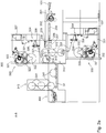
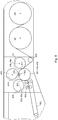
- the processing machine 01 preferably has at least one lamination device 300.
- the laminating device 300 preferably represents that device 300 which serves to enrich the flat material 02 with at least one additional layer of material and, in particular, to produce a laminated material web 02, which has further preferably provided predetermined separation points. Such a predetermined separation point results, for example, where two adjacent sheets 03 face each other, be it at a distance, be it with a frontal touch or be as preferred with an overlap.
- the preparation device 200 preferably passes on to the laminating device 300 a continuous stream of, in particular, slightly overlapped non-laminated sheets 03. This stream is at least in the laminating device 300 one-sided and preferably on both sides with at least one layer of a laminating substance 321; 331 coated.
- an overlapping region 06 in which two sheets 03 touch each other. In this area, these two sheets 03 are only at most on one side with the at least one lamination material 321; 331 in contact.
- the at least one lamination material 321; 331 forms the bond between the sheets 03.
- a severing of the at least one layer of laminating material 321; 331 separates the sections 04 from each other. Since the layer of lamination 321; 331 is preferably formed relatively thin, this overlap region 06 is preferably a predetermined separation point.
- An overstretching of the material web 02 causes in particular an overstretching of the layer of laminating material 321; 331 in the overlap area.
- a relatively small absolute overstretching of the material web 02 causes a large overstretching of the laminating material 321; 331 in the overlapping area, while in the area connected to the arc 03 practically no stretching takes place.
- the lamination device 300 itself preferably has at least one lamination unit 310.
- the at least one lamination unit 310 preferably serves for the application of lamination material 321; 331 on the flat material 02. If in the foregoing and / or below of flat material 02 is mentioned, this is in particular that material 02 to understand that comes from the material source 100 and in the at least one lamination 310 with at least one other Layer of lamination material 321; 331 is provided and then preferably separated into individual sections 04.
- the flat material 02 is in particular that material 02, which is finished by the processing machine 01, while the lamination material 321; 331 is that substance which effects the finishing of the flat material 02.
- Laminating fabric 321; 331 originates in particular from a lamination source 320; 330 and is preferably fed to the flat material 02.
- the lamination cloth 321; 331 is supplied for example in the form of at least one web, in particular at least one film and connected by pressing and / or heating with the material 02.
- the lamination device 300 itself preferably has at least one first lamination source 320 for lamination 321 and / or at least one second lamination source 330 for lamination 331.
- the at least one first lamination source 320 is embodied as at least one upper lamination source 320 and / or the at least one first lamination source 320 serves to apply a first lamination material 321 to a first side of the material web 02 and / or the sheet 03.
- the at least one second lamination source 330 is formed as at least one lower lamination source 330 and / or the at least one second lamination source 330 serves to apply a second lamination material 331 to a second side of the material web 02 opposite to the first side of the material web 02 and / or the arch 03 and / or the sheet 03.
- the laminating device 300 itself preferably has at least one cooling device 340.
- the at least one first lamination source 320 is preferably designed as a first roll-off device 320 and / or preferably has at least one first roll-holding station 322.
- the first lamination source 320 is further preferably designed as at least one first roll changer 320 and / or preferably has at least two first roll holding locations 322, in particular for simultaneously carrying at least two rolls of first lamination material 321.
- These first roll holding spaces 322 are preferably about a common first pivot axis 323 pivotally arranged, in particular common.
- the two first roll holding stations 322 can be exchanged for their positions by a common pivoting movement.
- the first roll-off device 320 which is designed as the first roll changer 320, permits a flying roll change, ie, joining a new web of laminating material 321 with an already largely unwound web of laminating substance 321 without stopping it.
- the processing machine 01 is stopped in order to supply the laminating substance 321 to change a new role. This happens because of training as the first roll changer 320 still very fast.
- the at least one first lamination source 320 preferably has at least one first web edge aligner 327, which in particular serves for aligning the lamination material 321 in the axial direction A.
- the at least one first web edge aligner 327 is preferably a first web edge aligner 327 for aligning only laminating material 321.
- the at least one first web edge aligner 327 has, for example, at least two alignment rollers preferably arranged in a movable frame, whose position in space determines the axial position of the particular first web aligner 327 Lamin istsstoffs 321 can be adjusted.
- an orientation of the laminating substance 321 relative to the axial direction A in the transport direction can change to the at least one first web edge aligner 327, in particular without changing the position of the associated roll of laminating material 321 with respect to the axial direction A.
- the position of the in particular first lamination material 321 relative to the axial direction A is set, in particular controlled or regulated, by displacement of the associated roll of the lamination material 321 with respect to the axial direction A.
- the at least one first lamination source 320 preferably has at least one first web tension control 324, which has, for example, at least one first dancer roller 326 and / or at least one first dancer lever 328.
- At least one first roller feed device is arranged, by means of which rollers of the laminating material 321 of the first roller unwinding device 320 can be fed.
- the at least one first roll feed device is designed, for example, as at least one crane and / or at least one lifting device and / or as at least one transporting carriage and / or as at least one rail system.
- the at least one first Rollenabspulvoretti 320 for example, each Roll holding 322 two support arms, more preferably each of which each has a preferably designed as a folding bearing tension shaft bearing.
- the at least one first reel-off device 320 has, for example, at least one tensioning shaft on which rollers of the lamination material 321 can be received and held by means of entrainment elements designed as clamping jaws.
- At least one tensioning shaft bearing preferably has a closure element, which in the case of a folding bearing is preferably pivotable about a closure axis. The tensioning shaft is inserted with its two ends into the two tensioning shaft bearings together with the roller of the laminating material 321.
- the two tensioning shaft bearings are each closed, preferably by the closure elements are pivoted to a closed position. Only if the respective tensioning shaft bearing is in a rotational angle position which lies within this permissible angular position range can the respective tensioning shaft bearing be opened.
- the at least one second lamination source 330 is preferably designed as a second roll-off apparatus 330 and / or preferably has at least one second roll holding space 332.
- the second lamination source 330 is further preferably designed as at least one second roll changer 330 and / or preferably has at least two second roll holding locations 332, in particular for simultaneously carrying at least two rolls of second lamination material 331.
- These second roll holding locations 332 are preferably about a common second pivot axis 333 pivotally arranged, in particular common.
- the two second roll holding stations 332 can be exchanged for their positions by a common pivoting movement.
- the second reel-off device 330 which is designed as a second reel splitter 330, preferably permits a flying reel change, that is to say a joining of a new web of lamination material 331 with an already largely unwound web of lamination material 331 without stopping it.
- the processing machine 01 is stopped to change the feeding of the lamination 331 to a new roll. This happens because of the Training as a second reel changer 330 still very fast.
- the at least one second lamination source 330 preferably has at least one second web edge aligner 337, which in particular serves to align the lamination material 331 in the axial direction A.
- the at least one second web edge aligner 337 is preferably a second web edge aligner 337 for aligning only laminating material 331.
- the at least one second web edge aligner 337 has, for example, at least two alignment rollers, preferably arranged in a movable frame, whose position in space determines the axial position of the particular second web aligner 337 Lamin istsstoffs 331 can be adjusted.
- an orientation of the lamination material 331 relative to the axial direction A in the transport direction can change to the at least one second web edge aligner 337, in particular without changing the position of the associated roll of lamination 331 with respect to the axial direction A.
- the relative to the axial direction A position of the particular second laminating fabric 331 is adjusted by shifting the associated role of the lamination 331 with respect to the axial direction A, in particular controlled or regulated.
- the at least one second lamination source 330 preferably has at least one second web tension control 334, which has, for example, at least one second dancer roller 336 and / or at least one second dancer lever 338.
- At least one second roller feeding device is arranged, by means of which rollers of the laminating substance 331 can be fed to the second roller unwinding device 330.
- the at least one second roll feed device is designed, for example, as at least one crane and / or at least one lifting device and / or as at least one transporting carriage and / or as at least one rail system.
- the at least one second Rollenabspulvoretti 330 for example, each role holding space 332 two support arms, of which more preferably each one preferably has designed as a folding bearing clamping shaft bearing.
- the at least one second roller unwinding device 330 is preferably designed analogously to the at least one first roller unwinding device 320.
- the lamination material 321 is preferably fed to a first lamination roller 311 of a lamination unit 310.
- the lamination material 331 is preferably fed to a second lamination roller 312 of the lamination unit 310.
- the first laminating roller 311 preferably forms a first laminating area 313 together with the second laminating roller 312 in its common contact pressure area.
- the lamination 03 in particular overlapping, preferably takes place.
- the at least one first laminating roller 311 is preferably a first laminating roller 311, preferably heated internally, for example by induction, in particular to at least 100 ° C.
- an inner stator with induction coil and a rotor essentially designed as a hollow cylinder Induction coil arranged.
- the at least one second laminating roller 312 is preferably a second laminating roller 312 which is heated in particular internally, for example by induction, preferably to at least 100 ° C.
- a second laminating roller 312 which is heated in particular internally, for example by induction, preferably to at least 100 ° C.
- an inner stator with induction coil and an induction coil rotor designed essentially as a hollow cylinder are arranged.
- the at least one second laminating roller 312 has a lateral surface a relatively soft material, such as rubber.
- the lamination unit preferably has at least one heating roller 316, in particular heated internally, for example by induction, preferably to at least 100 ° C., along a transport path of the laminating substance 331 in front of the second laminating roller 312.
- an inner stator with an induction coil and a rotor designed essentially as a hollow cylinder with induction coil is arranged.
- the at least one heating roller 316 preferably serves to heat the laminating substance 331.
- the at least one second laminating roller 312, on the other hand, preferably serves to maintain this temperature of the laminating substance 331 and the lamination 331 to the sheets 03.
- the at least one first laminating roller 311 preferably serves both to heat the lamination 321 and to press the lamination 321 against the laminations Bow 03.
- the lamination 321; 331 By heating the lamination 321; 331, this is preferably converted into a state in which a particularly effective connection with the arc 03 can be achieved. For example, this activates an adhesive and / or, by an at least partial phase transition, the lamination material 321; 331 self-adhesive.
- the pressure in the first lamination region 313 results in a particularly effective connection between lamination material 321; 331 on the one hand and bow 03 on the other.
- an additional press roller 317 is arranged, which forms a second lamination area 314 in particular in common with the first lamination roller 311 in its common contact area.
- the pressing roller 317 is particularly pressed against the first laminating roller 311.
- the pressing roller 317 is preferably designed to be heatable internally, in particular to at least 100 ° C.
- the at least one pressing roller 317 preferably has a jacket surface made of a relatively soft material, for example rubber.
- the second laminating roller 312 is displaceable orthogonal to the axial direction A, in particular to interrupt its contact with the first laminating roller 311 and / or the heating roller 316 or to change its contact pressure.
- the pressing roller 317 is orthogonal to the axial direction A displaceable, in particular to interrupt their contact with the first laminating roller 311 or to change its contact pressure.
- the laminating device 300 has at least two independently operable drives, one of which is associated with at least the first laminating roller 311 and of which another is associated with at least the heating roller 316.
- the second laminating roller 312 and / or the press roller 317 are drivable via a transmission by means of the same drive as the first laminating roller 311.
- the processing machine 01 has at least one pre-heater 209 which is capable of acting or acting on the material 02, in particular the sheets 03, along the transport path of the material 02 in front of the first lamination region 313.
- the process of bonding between material 02 and lamination material 321; 331 preferably be improved.
- at least one cooling device 340 is preferably arranged.
- the at least one cooling device 340 preferably has at least one cooling roller 341, more preferably at least one cooling roller 341 on each side of the material web 02, and even more preferably at least three cooling rollers 341.
- the cooling device 340 preferably serves to cool the material web 02 produced and / or laminated in the laminating plant 310.
- the laminating machine 01 preferably allows a process for laminating a material 02 and in particular for changing at least one roll of laminating material 321; 331, wherein the material 02 is preferably fed to a lamination unit 310 of the laminating machine 01 and there preferably by bonding to at least one lamination material 321; 331 is laminated and wherein the at least one lamination material 321; 331 preferably in a roll changer 320; 330 formed lamination source 320; 330 is unwound from at least one roll and wherein preferably two rolls of the at least one lamination material 321; 331 together about a common pivot axis 323; 333 of the at least one reel changer 320; 330 are pivoted and at least one of a hitherto unwound from the at least two roles originating web of at least one lamination 321; 331 with a web of the at least one lamination material 321 originating from a different one of the at least two rolls to be abraded from then on; 331 is connected
- At least one method of laminating a material 02 is used, wherein the at least one lamination material 321; 331 preferably in a at least as Rollenabspulvorplatz 320; 330 formed lamination source 320; 330 is unwound from at least one roll and wherein the reeled from the at least one roll lamination material 321; 331 preferably by at least one web edge aligner 327 of the at least one Rollenabspulvortechnisch 320; 330 is aligned at least with respect to the axial direction A and wherein preferably a web tension of the at least one roll unwound and around at least one dancer roll 326; 336 a web tension control 324; 334 the at least one Rollenabspulvortechnisch 320; 330 led lamination 321; 331 by means of this at least one dancer roller 326; 336 controlled and / or regulated.
- the lamination material 321 unwound from the at least one roll; 331 with respect to the axial direction A, it is preferable that the lamination material 321; 331 unwinding role with respect to the axial direction A moves.
- the sheets 03 are laminated on both sides. Should not be lamination. Thus, this would show that the sheets 03 would not or only incorrectly transported further after the lamination 310. Should however unintentionally only one one-sided lamination of the sheets 03 take place, so a web of material 02 would nevertheless be formed, which consists of a web-shaped laminating material 321; 331 and associated sheet 03 would exist. Such an error should be recognized. Therefore, the laminating machine 01 preferably has at least one lamination control device 348; 349 on. By means of the at least one lamination control device 348; 349 is an exclusively one-sided lamination of a web 02 recognizable.
- the at least one lamination control device 348; 349 exploit that the sheets 03 scaled to a web 02 are connected. As a result, there is an overlap area for every two sheets 03. In this overlapping area, each sheet 03 is only provided with a maximum of one lamination material 321; 331 connected. Now missing one of the two layers of lamination 321; 331, an arc 03 in the overlap area with no lamination 321; Connected 331 and can be in this overlap area of the adjacent bow 03 stand out.
- the laminating machine 01 has at least one material source 100 designed as a sheet feeder 100 for sheets 03 of a material 02 to be laminated and at least one laminating unit 310 and at least two laminating sources 320; 330 for each at least one sheet-like laminating substance 321; 331 and at least one lamination unit 310 for producing a double-sided laminated material web 02 from the sheets 03 and the respective at least one lamination material 321; 331 on.
- a material source 100 designed as a sheet feeder 100 for sheets 03 of a material 02 to be laminated
- the laminating machine 01 is characterized in that along a transport path provided for transporting the laminated material web 02 to a laminating region 313; 314 of the lamination unit 310, at least one lamination control device 348; 349 is arranged, which monitors a control room area, which lies outside of a transport space area, which is occupied by the intended for the laminated material web 02 transport path.
- the laminating machine 01 is alternatively or additionally characterized in that the at least one lamination control device 348; 349 is arranged monitoring a control room area having at least partially a minimum control distance from a Bruumlenkwalze 353.
- the minimum control distance is preferably less than 20 mm, more preferably less than 10 mm, even more preferably less than 5 mm and even more preferably less than 2 mm.
- the minimum control distance is preferably smaller than an overlap length of adjacent sheets 03 within the laminated material web 02. This ensures that the projecting region can be detected. Depending on the thickness of the sheets 03 and / or the lamination 321; 331, the minimum control distance can be adjusted.
- the overlapping length of adjacent sheets 03 is in particular that along the intended transport path of the material web 02 measured length on which adjacent sheet 03 within the laminated material web 02 touch, at least as long as no area protrudes.
- the overlap length is preferably at least 2 mm, more preferably at least 3 mm, and even more preferably at least 4 mm, and independently preferably at most 20 mm, more preferably at most 10 mm, and still more preferably at most 6 mm.
- the laminating machine 01 is alternatively or additionally characterized in that the at least one lamination control device 348; 349 has at least one control element 351, which is designed as a detector 351. Further preferably, the laminating machine 01 is characterized alternatively or additionally in that the at least one lamination control device 348; 349 has at least one control element 352, which is designed as a transmitting device 352. Then a specific signal can be sent and received. The signal must preferably pass through the control room area. If there is an obstacle in the control room area, the signal will not be received. As an obstacle is essentially only the protruding part of a bow 03 in question. The absence of the signal may then indicate a lack of lamination 321; 331 be closed.
- the signal is preferably an electromagnetic signal, in particular an optical signal, for example a laser beam.
- the laminating machine 01 is alternatively or additionally characterized in that the at least one lamination control device 348; 349 has at least one control element 351, which is designed as an electromagnetic radiation detector 351, and that the at least one lamination control device 348; 349 has at least one control element 352, which is designed as a transmitting device 352 for electromagnetic radiation.
- the laminating machine 01 is alternatively or additionally characterized in that a rectilinear section of a beam path between the control element 352 designed as a transmitting device 352 on the one hand and the control element 351 formed as a detector 351 on the other hand passes a lateral surface of the web deflecting roller 353 with the minimum control distance.
- the beam path can in this case run directly from the control element 352 designed as a transmitting device 352 to the control element 351 designed as a detector 351 or can be deflected via at least one reflector.
- the laminating machine 01 preferably additionally or additionally by the fact that the laminating machine 01 at least two lamination control devices 348; 349, of which a first lamination control device 348 is arranged on a first side of the transport path provided for the laminated material web 02 and of which a second lamination control device 349 is arranged on a second, opposite side of the first side of the transport path provided for the laminated material web 02.
- the laminating machine 01 is characterized in that the first laminating control device 348 is arranged monitoring a first control room area which at least partially has a minimum control distance from a first web deflecting roller 353 and the second laminating control device 349 is arranged monitoring a second control room area, which at least partially has a minimum control distance from a second web deflection roller 353, and that the minimum control distance as described is less than 20 mm, more preferably less than 10 mm, even more preferably less than 5 mm and even more preferably less than 2 mm and / or smaller than an overlapping length of adjacent sheets 03 within the laminated material web 02.
- the web of material 02 preferably touches the two web deflection rollers 353 with different sides, so that each of the two lamination controls facilities 348; 349 a lack of another layer of lamination 321; 331 can capture.
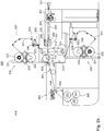
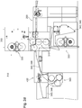
- the laminating machine 01 preferably has the at least one separating device 400 for separating sections 04 from the laminated material web 02.
- the at least one lamination control device 348; 349 is preferably along the transport path provided for transporting the laminated material web 02 to a lamination region 313; 314 of the lamination 310 and upstream of the separator 400. This is the area in which the laminated material web 02 is present.
- the presence of lamination materials 321; 331 is therefore preferably carried out in the area in which the material web 02 is present and not in the area in which individual sections 04 are already present again.
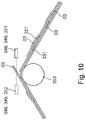
- This separating device 400 preferably has at least one first expansion element 403, wherein by moving at least the at least one first expansion element 403 between at least one first passing layer and at least one first separating layer, the separating device 400 can be switched between at least one passing state and at least one separating state, and wherein at least one separating sensor device 463 is arranged for detecting a gap between the material web 02 and a respectively last separated section 04.
- at least one separating sensor device 463 is arranged for detecting a gap between the material web 02 and a respectively last separated section 04.
- the at least one control element 351 designed as a detector 351 is alternatively or additionally designed, for example, as a light reflection key 351.
- the control room area can also be monitored.
- Elements of an arc 03 penetrating into this light reflection key 351 directly or diffusely reflect parts of electromagnetic radiation, in particular light. These reflected parts can be detected by the detector 351.
- a control element 352 is again arranged, which is designed as a transmitting device 352.
- This transmitting device 352 forms, for example, with the detector 351 a structural unit and can then be arranged in a particularly space-saving manner.
- At least one ultrasonic sensor and / or at least one capacitive sensor is arranged in order to monitor the respective control room area.
- the processing machine preferably has the at least one separating device 400.
- the at least one separating device 400 is preferably designed for separating the in particular laminated material web 02 into individual sections 04 and / or for separating sections 04 from the in particular laminated material web 02.
- the at least one separating device 400 preferably has at least one front clamping device 406 with at least one front clamping point 401 and at least one rear clamping device 404 with at least one rear clamping point 402 and at least one first expansion element 403.
- the at least one front clamping point 401 is arranged along the intended transport path in front of the at least one rear clamping point 402.
- the separation device 400 can be switched between at least one pass state and at least one separation state.
- the pass state is preferably a state in which the expansion elements 403; 412; 413, allow the web 02 to pass unhindered through the separator 400, for example, depending on the embodiment, straight between the front nip 401 and the rear nip 402 or along a circular arc between the front nip 401 and the rear nip 402. Preferably, this is done only temporarily, in particular in order to achieve a feed, so that a next planned predetermined separation point reaches a corresponding position.
- a vertical reference plane preferably has a horizontal normal vector.
- a normal vector is in vector which is oriented orthogonal to each line completely contained in the corresponding plane. More preferably, the normal vector points in a direction that runs in or against the axial direction A.
- a particular respective transport line is preferably a shortest and any component of the separating device 400 lying on a respective same side as a transport path provided for the material web 02 and / or the sections 04 and / or tangent between the at least one front terminal 401 on the one hand and the at least one rear nip 402 on the other.
- the same side should be understood in particular to mean that the transport path, viewed from the corresponding component, is closest to this component essentially in the same direction in which the transport line is also closest to this component.
- the transport line is longer in the at least one separation state than in the at least one pass state, in particular by at least 2 mm, more preferably at least 4 mm and even more preferably at least 6 mm.
- a corresponding region of the web 02 is stretched and thereby preferably takes place at a designated predetermined separation point of the web 02 separating a corresponding portion 04 of the Material web 02.
- an area of influence of the at least one first expansion element 403 is arranged along the transport line between the at least one front clamping device 406 and the at least one rear clamping device 404.
- the separation is preferably carried out by stretching and in particular overstretching of the material web 02 and more preferably not by cutting the material web 02.
- the at least one first expansion element 403 preferably has a contact surface 462 which is provided for contact with the material web 02 and / or the sections 04.
- the contact region in which such a contact actually exists between the material web 02 and the first expansion element 403, varies cyclically.
- the contact line is the intersection between this contact area on the one hand the Reference level, on the other hand.
- the at least one first expansion element 403 and in particular its contact line at least in the contact region exclusively on a convex curvature, wherein the radius of curvature is not necessarily the same everywhere, but preferably varies in the circumferential direction.
- This radius of curvature is, for example, always at least 0.05 mm, preferably at least 0.1 mm, more preferably at least 0.5 mm and even more preferably at least 2 mm and even more preferably at least 10 mm.
- the material web 02 is stretched, in particular overstretched and more preferably not cut, by the at least one first expansion element 403.
- the transport line has a smallest radius of curvature which is at least 0.05 mm, preferably at least 0.1 mm, more preferably at least 0.5 mm and even more preferably at least 2 mm and even more preferably at least 10 mm , Then it is ensured that at no other point along the transport line, a cutting of the material web 02 takes place.
- the at least one first expansion element 403 is preferably designed such that viewed along the axial direction A, a maximum radius of the at least one first expansion element 403 increases and / or varies.
- the separating device 400 is therefore preferably characterized in that a first reference plane and a second reference plane in the axial direction A are arranged spaced from each other and that are arranged in the at least one first separating layer first expansion element 403 a particular completely lying in the first reference plane first transport line and a particular completely lying in the second reference plane second transport line are different lengths and / or that a maximum Movement radius of the at least one first expansion element 403 in the first reference plane is greater than in the second reference plane.
- the at least one first expansion element 403 is arranged eccentrically about a first expansion axis 414 pivotable and / or rotatable. In this way, a periodically recurring enlargement and reduction of the transport line can be achieved in a simple manner by means of a rotational movement.
- neither the first clamping device 406 nor the second clamping device 404 has one or more grippers.
- at least one application device 461 is arranged, in particular around the leading end resulting from the separation the material web 02 in the rear nip 402 to pass.
- the at least one application device 461 has, for example, at least one in particular also downwardly directed blown air nozzle.
- the at least one contact device 461 is designed as at least one baffle penetrated by a multiplicity of gas nozzles, these gas nozzles preferably being connected via a common chamber and / or being connected to a compressed air source.
- the at least one separating device 400 preferably has, in addition to at least one first movable expansion element 403, at least one second expansion element 412 and more preferably at least one third expansion element 413. This can also be done at small movement of the individual expansion elements 403; 412; 413 a total of a large elongation of the web 02 can be achieved.
- the at least one separating device 400 is characterized in that the at least one separating device 400 has at least one second expansion element 412 that is movable between a second passing position and a second separating position and that the at least one separating device 400 has at least one third expansion element 413 is movable between a third passing position and a third separating position.
- the at least one second expansion element 412 is preferably arranged along the transport path provided for the material web 02 in front of the at least one first expansion element 403 and in front of the at least one third expansion element 413.
- the at least one first expansion element 403 is preferably arranged along the transport path provided for the material web 02 after the at least one second expansion element 412 and in front of the at least one third expansion element 413.
- the at least third expansion element 413 is preferably arranged along the transport path provided for the material web 02 after the at least one second expansion element 412 and after the at least one first expansion element 403.
- the at least one first expansion element 403 preferably has at any time a distance, which is different from zero, from the at least one second expansion element 412, in particular with respect to a direction orthogonal to the axial direction A.
- the at least one first expansion element 403 preferably has at any time a distance different from zero from the at least one third expansion element 413, in particular with respect to a direction orthogonal to the axial direction A.
- the at least one second expansion element 412 preferably has at any time a distance different from zero from the at least one third expansion element 413, in particular with respect to a direction orthogonal to the axial direction A.
- the at least one separating device 400 is characterized in that at least one rectilinear connection between the at least one second expansion element is arranged in the first separating element arranged first expansion element 403 and in the second separating layer arranged second expansion element 412 and arranged in the third separation layer third expansion element 412 and the at least one third expansion element 413 which intersects at least one first expansion element 403, in particular in the geometric sense.
- the at least one separating device 400 is characterized in that the at least one first expansion element 403 is arranged eccentrically pivotable and / or rotatable about a first expansion axis 414 and / or that the at least one second expansion element 412 is eccentrically pivotable about a second expansion axis 416 and / or. or is rotatably arranged and / or that the at least one third expansion element 413 is arranged eccentrically about a third expansion axis 417 pivotally and / or rotatably.
- a periodically recurring enlargement and reduction of the transport line can be achieved in a simple manner by means of a plurality of rotational movements.
- the at least one first expansion element 403 and the at least one second expansion element 412 and the at least one third expansion element 413 are preferably drivable by means of at least one common drive and / or coupled to one another via at least one transmission.
- the first strain axis 414 is spaced from the second strain axis 416 and / or from the third strain axis 417.
- the second strain axis 416 is spaced from the third strain axis 417.
- the first strain axis 414 is arranged parallel to the second strain axis 416 and / or parallel to the third strain axis 417.
- the second is preferred Elongation axis 416 arranged parallel to the third strain axis 417.
- the first strain axis 414 and / or the second strain axis 416 and / or the third strain axis 417 are oriented parallel to the axial direction A.
- the at least one second expansion element 412 has at least in its contact region and in particular its contact line exclusively one or more convex curvatures, wherein the radius of curvature is not necessarily the same everywhere, but preferably varies in the circumferential direction.
- This radius of curvature is, for example, always at least 0.05 mm, preferably at least 0.1 mm, more preferably at least 0.5 mm and even more preferably at least 2 mm and even more preferably at least 10 mm.
- the at least one third expansion element 413 has at least in its contact region and in particular its contact line exclusively one or more convex curvatures, wherein the radius of curvature is not necessarily the same everywhere, but preferably varies in the circumferential direction.
- This radius of curvature is, for example, always at least 0.05 mm, preferably at least 0.1 mm, more preferably at least 0.5 mm and even more preferably at least 2 mm and even more preferably at least 10 mm. This ensures that the material web 02 is stretched and not cut by the at least one second expansion element 412 and the at least one third expansion element 413 in each case.
- the at least one second expansion element 412 and the at least one third expansion element 413 are preferably not designed as knives.
- Optionally existing concave curvatures usually do not contribute to the contact surface.
- the at least one guide 418; 419 is, for example, as at least one flat, in particular rigidly arranged guide device 419, in particular as at least one baffle 419 formed and / or is formed, for example, as at least one belt control system 418.
- both at least one belt control system 418 and at least one planar, in particular rigidly arranged guide 419 are arranged.
- the at least one separating device 400 is alternatively or additionally characterized in that the at least one separating device 400 has at least one belt control system 418 which has a plurality of conveyor belts 431 arranged one behind the other in an axial direction A and those in between in this axial direction A. are located intermediate spaces.
- the at least one second expansion element 412 in its second separating layer and / or the at least one third expansion element 413 in its third separating layer are each preferably arranged at least partially projecting through the intermediate spaces. In this way, the transport line is further lifted over the conveyor belts 431 and thereby extended. If then the at least one first expansion element 403 is still immersed between the at least one second expansion element 412 and the at least one third expansion element 413, the transport line is additionally extended without the at least one first expansion element 403 having to reach under the conveyor belts 431.
- the at least one separating device 400 is alternatively or additionally characterized in that the at least one second expansion element 412 is arranged in its second passing position and / or the at least one third expansion element 413 is disposed completely outside of a half space in its third passing position
- Conveyor belts 431 defined transport plane is limited and in which the at least one first expansion element 403 is arranged in its first separation layer and / or in its first pass position.
- This half-space is preferably arranged above the conveyor belts 431.
- a half-space is to be understood as meaning, in particular, that region of space which is bounded exclusively by one of a plane. Each level divides the entire space into two half-spaces.
- At least one baffle 419 is arranged, which supports the material web 02 and / or the sections 04 at least from below at least where the spaces between the conveyor belts 431 are arranged and at the same time no room for movements of any expansion element 403; 412; 413 is necessary.
- the at least one separating device 400 is characterized in that the at least one front clamping device 406 has at least one front tension roller 408 or inlet tension roller 408 and at least one front pressure roller 407 or inlet pressure roller 407 attached thereto and / or engageable and / or that the at least one rear one Clamping device 404 has at least one rear tension roller 411 or outlet tension roller 411 and at least one attached thereto and / or adjustable rear pressure roller 409 or outlet pressure roller 409.
- the at least one separating device 400 is characterized in that the front draw roller 408 has a first plurality of circumferential recesses 432 and / or that the front pressure roller 407 has a plurality of circumferential recesses 433, in particular identical to the first plurality.
- a depth of the recesses 432 of the front draw roller 408 is greater than a thickness or smallest dimension of the conveyor belts 431.
- the conveyor belts 431 may be arranged in the recesses 432, without coming into contact with the material web 02 or the sections 04 or at least with only a weak force. This allows a minimal or greater difference between a speed at which the conveyor belts 431 are moved and a speed at which the web 02 or the sections 04 are moved and a peripheral speed of the front tension roller 408 and / or the front pressure roller 407 and / or the rear tension roller 411 and / or the rear pressure roller 409 corresponds.
- the peripheral circumferential recesses 432 of the front tension roller 408 are formed narrower in the axial direction A than the circumferentially circumferential recesses 433 of the front pressure roller 407 and / or circumferential recesses 432 of the front tension roller 408 in pairs in the circumferential direction circumferential recesses 433 of the front pressure roller 407 arranged opposite.
- the at least one front draw roll 408 preferably has a jacket surface made of a wear-resistant material, for example steel and / or chromium and / or ceramic and / or a hard metal alloy such as WC / Co, Cr 3 C 2 / NiCr, NiCrBSi, WC / Ni , TiC / Ni, molybdenum or the like, which was more preferably applied in a thermal spraying process.
- the at least one front pressure roller 407 preferably has a lateral surface made of a relatively soft material, for example rubber. This ensures that the material web 02 and / or the sections 04 are reliably transported forward and / or clamped and that nevertheless no embossing by edges of the recesses 432; 433 are generated.
- the at least one separating device 400 is characterized in that the rear tension roller 411 has a plurality of recesses 432 which are identical in circumference, in particular with the first plurality and which preferably substantially correspond to the recesses 432 of the front tension roller 408 and / or the rear one Pressure roller 409 has a plurality of circumferentially circumferential recesses 433, in particular with the first plurality identical, preferably substantially the recesses 433 of the front pressure roller 408th correspond.
- the circumferentially circumferential recesses 432 of the rear tension roller 411 are formed narrower in relation to the axial direction A than the circumferentially circumferential recesses 433 of the rear pressure roller 409 and / or circumferential recesses 432 of the rear tension roller 411 in pairs in the circumferential direction circumferential recesses 433 of the rear pressure roller 409 arranged opposite.
- the at least one rear tension roller 411 preferably has a jacket surface made of a wear-resistant material, for example steel and / or chromium and / or ceramic and / or a hard metal alloy such as WC / Co, Cr 3 C 2 / NiCr, NiCrBSi, WC / Ni , TiC / Ni, molybdenum or the like, which was more preferably applied in a thermal spraying process.
- the at least one rear pressure roller 409 preferably has a lateral surface made of a relatively soft material, for example rubber. For example, a depth of the recesses 432 of the rear tension roller 408 is greater than the thickness or smallest dimension of the conveyor belts 431. Alternatively, the recesses 432 of the rear tension roller 408 are the same size as the thickness or smallest dimension of the conveyor belts 431.
- the front tension roller 408 has its own drive motor, which in particular serves to regulate the speed at which the material web 02 is transported through the front clamping point 401.
- the front pressure roller 407 is preferably passively driven via contact with the front tension roller 408.
- the rear tension roller 411 has its own drive motor, which in particular serves to regulate the speed with which the material web 02 and / or the respective section 04 is transported through the rear clamping point 402.
- the rear pressure roller 409 is preferably passively driven via contact with the rear tension roller 411.
- the at least one separating device 400 is alternatively or additionally characterized in that the at least one first expansion element 403 and / or the at least one second expansion element 412 and / or the at least one third expansion element 413 via a common drive and / or independently can be driven by the front clamping device 406 and / or the rear clamping device 404.
- At least one Trenneinlaufwalze 429 is arranged, which ensures a correct supply of the material web 02 to the separator 400.
- the conveyor belts 431 at an angle of at least 90 ° with the rear tension roller 411 in contact and are driven by this.
- another roller is responsible for driving the conveyor belts 431, for example, a roller arranged along the transport path of the sections 04 to the rear tension roller 411.
- Preferred are one or more guide rollers 426; 427, which guide the conveyor belts 431 around the front tension roller 408. Then, the conveyor belts 431 have little contact with the front tension roller 408 and can be driven independently thereof.
- at least one tension roller 428 is arranged, which serves to adjust the tension of the conveyor belts 431.
- the separation device 400 in particular in place of the second and third expansion elements 412; 413 at least one support cylinder 451, which has at least one first cylinder channel 452.
- This separating device 400 then preferably has at least one expansion cylinder 453 cooperating with the support cylinder 451, which carries the at least one first expansion element 403 and has at least one second cylinder channel 454.
- the second cylinder channel 454 preferably extends in the circumferential direction by at least 30 ° and more preferably at least 90 ° and at most 270 ° and more preferably at most 180 ° about the at least one expansion cylinder 453.
- the separator 400 at least a first clamping cylinder 456, the has at least a first clamping elevation 457, which preferably forms the front clamping device 406 in at least one clamping position with the support cylinder 451.
- the at least one first clamping elevation 457 preferably extends in the circumferential direction by at least 90 ° and more preferably at least 180 ° and preferably at most 30 ° and further preferably at most 90 ° about the at least one first clamping cylinder 456.
- the separating device 400 then has at least one second clamping cylinder 458, which has at least one second clamping elevation 459, which preferably forms the rear clamping device 404 in at least one clamping position with the support cylinder 451 ,
- the at least one second clamping elevation 459 preferably extends in the circumferential direction by at least 90 ° and more preferably at least 180 ° and preferably at most 30 ° and more preferably at most 90 ° about the at least one second clamping cylinder 458.
- the at least one support cylinder 451 preferably has a jacket surface made of a wear-resistant material, for example steel and / or chromium and / or ceramic and / or a hard metal alloy such as WC / Co, Cr 3 C 2 / NiCr, NiCrBSi, WC / Ni, TiC / Ni, molybdenum or the like, which was more preferably applied in a thermal spray process.
- a wear-resistant material for example steel and / or chromium and / or ceramic and / or a hard metal alloy
- WC / Co WC / Co
- Cr 3 C 2 / NiCr NiCrBSi
- WC / Ni TiC / Ni, molybdenum or the like
- the expansion cylinder 453 and / or the first clamping cylinder 456 and / or the second clamping cylinder 458 each have a lateral surface made of a relatively soft material, for example rubber.
- the at least one separating device 400 preferably allows a method for separating at least a portion 04 of a material web 02.
- first sheet 03 are removed from a sheet stack 102 and isolated, especially so far in that each sheet 03 is at a distance from its directly adjacent sheets 03.
- the separated sheets 03 are preferably aligned individually.
- the aligned sheets 03 are preferably shingled into a Location relative to each other.
- each subsequent sheet 03 is partially placed under a leading sheet 03. This arrangement is called subsquading.
- the scalloped arranged, but in particular still relatively independent arc 03 by means of at least one lamination 321; 331 connected to a material web 02.
- the material web 02 is, in particular independently of its formation, preferably clamped in at least one front clamping point 401 of at least one front clamping device 406 and clamped in at least one rear clamping point 402 at least one rear clamping device 404.
- a transport line is preferably a completely located in a vertical reference plane shortest any component of the separator 400 on a respective same side as the material web 02 and / or the at least one section 04 passing or tangent connection between the at least one front clamping point 401 on the one hand and the at least one rear nip 402 on the other.
- At least one first expansion element 403 is moved from a first passing position into a first separating position, and as a result the transport line is stretched so far that the at least one section 04 tears off the material web 02.
- the at least one section 04 tears off the material web 02 by the at least one lamination material 321; 331 rips.
- the material web 02 preferably tears at a respective intended predetermined separation point.
- the severed section 04 is preferably initially clamped to the rear clamping point 402 and can therefore be guided and transported further by the rear clamping device 402.
- the material web 02 is at least initially clamped to the front clamping point 401 and can therefore be further guided and transported by the front clamping device 401.
- the movement of the at least one first expansion element 403 from the first passing layer into the first separating layer takes place while the material web 02 and optionally already separated sections 04 are transported along the transport path forward.
- a transport of the material web 02 and the separated sections 04 does not need to be interrupted. This is preferably made possible by the fact that the clamping points 401; 402 are formed by rotating components.
- the web 02 is clamped both at the front nip 401 and at the rear nip 402 and is due to the rotation of the front tension roller 408 about the rotation axis 422 and the front pressure roller 407 about the rotation axis 421 and the rear tension roller 411 about the rotation axis 424th and the rear nip roll 409 about its axis of rotation 423 yet through both nips 401; 402 transported.
- the at least one second expansion element 412 is pivoted about its second expansion axis 416 and thereby brought into a spatial region which previously occupies the material web 02.
- the at least one second expansion element 412 thereby rises, for example, over a plane formed by the conveyor belts 431.
- the transport line is deflected, in particular raised, and thereby stretched or extended.
- a rotational direction of the at least one second expansion element 412 is selected so that the at least one second expansion element 412 in the layers, in particular separation layers in which it extends the transport line, has a movement component which runs parallel to a transport direction of the material web 02. This preferably results in as little relative movement between the material web 02 and the at least one second expansion element 412. Unwanted damage to the material web 02 is thereby reduced or avoided.
- An angular range of movement of the at least one second expansion element 412 in which the at least one second expansion element 412 projects at least partially beyond the plane formed by the conveyor belts 431 is preferably at least 100 ° and more preferably at least 120 ° and preferably at most 150 ° and more preferably at most 130 °.
- the at least one third expansion element 413 is pivoted about its third expansion axis 417 and thereby brought into a spatial region, which previously occupies the material web 02.
- the at least one third expansion element 413 thereby rises, for example, over the plane formed by the conveyor belts 431.
- the transport line is deflected, in particular raised, and thereby stretched or extended.
- a rotation direction of the at least one third expansion element 413 is selected such that the at least one third expansion element 413 has a component of movement in the layers, in particular separation layers in which it extends the transport line, which component runs parallel to a transport direction of the material web 02.
- An angular range of movement of the at least one third expansion element 413 in which the at least one third expansion element 413 projects at least partially beyond the plane formed by the conveyor belts 431 is preferably at least 100 ° and more preferably at least 120 ° and preferably at most 150 ° and more preferably at most 130 °.
- the at least one first expansion element 403 is pivoted about its first expansion axis 414 and thereby at least partially brought into a spatial region which at this time is arranged between parts of the at least one second expansion element 412 and parts of the at least one third expansion element 413 is.
- the at least one first expansion element 403 is thereby lowered, for example, between the at least one second expansion element 412 and the at least one third expansion element 413.
- the transport line is further extended, in particular by being prevented and / or lowered from lifting in this region, and thereby stretched or extended.
- a rotational direction of the at least one first expansion element 403 is selected so that the at least one first expansion element 403 in the layers, in particular separating layers in which it extends the transport line, has a movement component which runs parallel to a transport direction of the material web 02.
- This preferably results in the least possible relative movement between the material web 02 and the at least one first expansion element 403. Unwanted damage to the material web 02 are thereby reduced or avoided.
- the method is preferably characterized in that, for stretching the transport line, at least one second expansion element 412 is moved from a second pass position to a second separation position and / or at least a third expansion element 413 is moved from a third pass position to a third separation position and the transport line with respect to its curvature gets at least one additional turning point, especially by.
- a turning point is in particular a point at which a curvature changes its direction and / or its preference.
- the predetermined separation point is preferably located with respect to the transport path of the material web 02 in the region of the at least one first expansion element 403.
- the severed portion 04 is transported further by the rear clamping device 404.
- the leading end of the material web 02 is preferably at the latest after a further movement of the expansion elements 403; 412; 413 on the conveyor belts 431 and is guided by these in the rear clamping device 404. Thereafter, the cycle starts again. While the expansion elements 403; 412; 413 are arranged in their respective passages, they are preferably out of contact with the material web 02.
- the method is alternatively or additionally characterized in that the at least one first expansion element 403 and / or the at least one second expansion element 412 and / or the at least one third expansion element 413 independent of the front clamping device 406 and / or independently of the rear clamping device 404 and / or with a particular respective periodically fluctuating angular velocity is driven.
- the at least one first expansion element 403 and / or the at least one second expansion element 412 and / or the at least one third expansion element 413 independent of the front clamping device 406 and / or independently of the rear clamping device 404 and / or with a particular respective periodically fluctuating angular velocity is driven.
- a relative speed between material web 02 on the one hand and first expansion element 403 and / or second expansion element 412 and / or third expansion element 413 on the other hand can be kept as low as possible, in particular although the speed of the respective expansion element 403; 412; 413 because of its rotation most of the time over in a component parallel to the transport direction of the web 02 and a component orthogonal to it divides.
- the method is alternatively or additionally characterized in that an angular velocity of the at least one second expansion element 412 during its contact with the material web 02 is initially reduced and subsequently increased again and / or at a distance from the material web 02 as a function of one provided Section length varying angular velocity is driven and / or that an angular velocity of the at least one third expansion element 413 during its contact with the material web 02 is initially reduced and subsequently increased again and / or at a distance to the material web 02 with varying depending on an intended section length angular velocity is driven.
- the method is characterized alternatively or additionally in that an angular velocity of the at least one second expansion element 412 always coincides with an angular velocity of the at least one third expansion element 413.
- the severing device 400 for severing portions 04 of a web of material 02 which preferably has at least one front clamping device 406 with at least one front clamping point 401 and at least one rear clamping device 404 with at least one rear clamping point 402 and at least one first expansion element 403 as described
- the separation device 400 can be switched between at least one pass state and at least one separation state, or the laminating machine 01 having this separation device 400 preferably has at least one separation sensor device 463.
- This at least one separation sensor device .463 is preferably connected in terms of circuitry to a machine control of the laminating machine 01.
- At least one separation sensor device 463 is arranged for detecting a respective gap between the material web 02 and the respectively last separated section 04. By means of this separation sensor device 463 can thus be monitored whether a separation of a portion 04 of the material web 02 has been successful.
- the separation sensor device 463 preferably measures directly in the region in which the separation takes place, ie in the region of the separation device 400.
- the separation device 400 is preferably characterized in that the at least one separation sensor device 463 has at least two sensor elements 464; 466; 467 and that at least one rectilinear connection of these at least two sensor elements 464; 466; 467 cuts an intended transport path of the material web 02 through the separating device 400.
- a measurement of a signal which can be determined at the moment of the separation. For example, by the overstretching and tearing of the portion 04 of the web 02 at least for a short time a narrow gap between the web 02 on the one hand and the just-separated section 04 on the other hand generated. Through this gap, a signal can be transmitted, for example an electromagnetic signal, in particular a light signal.
- the signal is transmitted, it is confirmed that the gap has existed, at least for a short time, even if a subsequent reduction of the transport line by movement of the expansion elements 403; 412; 413 overlaps the trailing end of the section 04 that has just been produced, again with a straight leading end of the material web 02 that has just been produced, and interrupts the signal again.
- the subsequent overlap does not call into question the successful separation of section 04.
- the separation device 400 is characterized in that the at least one separation sensor device 463 has at least one first sensor element 467 which is arranged above a planned transport path of the material web 02 by the separation device 400 and that the at least one separation sensor device 463 at least one second sensor element 464; 466, which is arranged below the transport path of the material web 02 by the separating device 400.
- the at least one separation sensor device 463 preferably has at least one sensor element 464 designed as a detector 464, which is further preferably designed as at least one as a detector 464 for electromagnetic radiation.
- the at least one separation sensor device 463 preferably has at least one sensor element 466 designed as a transmission device 466 for electromagnetic radiation.
- the transmitting device 466 is a light source, in particular a light-emitting diode.
- the at least one detector 466 is designed as a light sensor 466 or photocell 466.
- the separation device 400 is characterized in that the at least one separation sensor device 463 has at least one reflector 467 Sensor element 467, which is designed in particular as a reflector 467 for electromagnetic radiation.
- the separation device 400 is preferably characterized in that at least one sensor element 464; 466; 467 is movably arranged together with the at least one first expansion element 403 and / or that at least one sensor element 464; 466; 467 is stationary relative to the at least one first expansion element 403 is arranged.
- the at least one sensor element 467 designed as a reflector 467 is preferably movably arranged together with the at least one first expansion element 403 and / or arranged stationary relative to the at least one first expansion element 403.
- At least one sensor element 464; 466; 467 fixedly arranged relative to a frame of the separation device 400, wherein more preferably at least one formed as a detector 464 sensor element 464 stationary relative to the frame of the separator 400 is disposed and / or the at least one transmitting device 466 designed as a sensor element 466 stationary relative to the frame the separating device 400 is arranged.
- the at least one detector 464 is designed as a sensor element 464, which is arranged below the transport path of the material web 02 through the separation device 400 and the at least one transmitting device 466 for electromagnetic radiation is designed as a sensor element 466 which is below the transport path of the material web 02 arranged by the separating device 400 and the at least one reflector 467 is formed as a sensor element 467, which is arranged above the intended transport path of the material web 02 by the separating device 400. Electromagnetic radiation emitted by the transmitting device 466 can then be reflected by the reflector 467 and directed to the detector 464 with a corresponding relative orientation. However, this is only possible as long as neither the Material web 02 still separate sections 04 interrupt the beam path.
- the separation device 400 is characterized in that at least and further preferably only in its separation layer arranged first expansion element 403 emanating from the transmitting device 466 beam path of electromagnetic radiation through a reflector 467 of the separation sensor device 463 and directed to the detector 464 of the separation sensor device 463 is.
- the beam path through the web of material 02 is interrupted until a separation has just taken place and / or takes place.
- a situation in which a reflection and thus a registration of a corresponding signal is possible, is preferably only given when the first expansion element 403 is just located in its separation position and the transport line is just so far increased that a portion 04 of the material web 02 is demolished and the overlap is lifted at this point and a gap between web 02 and 04 has arisen.
- the first expansion element 403 must preferably be arranged in its separating layer.
- the separation device 400 is characterized by the fact that at least and further preferably only when the first expansion element 403 is arranged in its separation position, a transmission direction from the at least one transmission device 466 points directly to a detector 464 of the separation sensor device 463.
- a confirmation of a successful separation of a section 04 from the material web 02 should then take place once per movement cycle of at least the first expansion element 403. This is preferably monitored by means of a machine control. In the absence of the expected signal is a Error before, for example, an incomplete or missing separation. In response, for example, the operation of the separator 400 and / or the laminating machine 01 is interrupted.
- the method is preferably characterized in that the at least one first expansion element 403 assumes a position in its separating position in which it is cut by a linear connection between two channel edge defining the first cylinder channel 452 and thereby the transport line with respect to its curvature at least one additional Turning point gets.
- the material web 02 extends between the front nip 401 and the rear nip 402.
- the front nip 401 is defined by a front clamp 406, in this case by the support cylinder 451 on the one hand and the at least one first clamp cylinder 456 and in particular its first clamp 457th on the other hand is formed.
- the rear clamping point 402 is determined by a rear clamping device 404, which is formed in this case by the support cylinder 451 on the one hand and the at least one second clamping cylinder 458 and in particular its second clamping elevation 458 on the other.
- the first expansion element 403 attached to it dips into the first cylinder channel 452 of the support cylinder 451 then opposite the at least one expansion cylinder 453.
- the elongation or stretching of the transport line and thus the tearing of the material web 02 takes place analogously to the method by means of the first embodiment of the at least one separating device 400.
- the severed portion 04 is passed from the rear nip 402 to a device 502; Passing 503, which ensures its safe onward transport, for example, a further nip 503 or a conveyor belt 502 or a suction belt 502.
- a device 502 Passing 503 which ensures its safe onward transport, for example, a further nip 503 or a conveyor belt 502 or a suction belt 502.
- the circumference of the first clamping cylinder 456 is preferably divided into the first clamping elevation 457 on the one hand and a portion 04 lowered thereon on the other hand, that the first clamping cylinder 456 temporarily out of contact with the support cylinder 451 device.
- the circumference of the second clamping cylinder 458 is preferably divided into the second clamping elevation 459 on the one hand and a portion 04 lowered on the other hand, that the second clamping cylinder 458 temporarily out of contact with the support cylinder 451, in particular simultaneously with the first clamping cylinder 456.
- the second cylinder channel 454 of the at least one expansion cylinder 453 is preferably also selected in its position and extent in the circumferential direction so that at the same time the at least one support cylinder 451 with the at least one expansion cylinder 453 out of contact.
- the support cylinder 451 can be rotated without affecting the material web 02. Instead, a sliding of the material web on the support cylinder 451 takes place in this time.
- the support cylinder 451 preferably has one opening or a plurality of openings for sucking and / or expelling gas, in particular air, for example in order to selectively hold and / or release the material web 02 arranged thereon and / or the part of the corresponding section 04 arranged thereon.
- the second cylinder channel 454 of the at least one expansion cylinder 453 and the second clamping elevation 459 of the second clamping cylinder 458 are preferably selected in their respective position and extent in the circumferential direction so that after a Separating the section 04 from the material web 02 a leading end of the web 02 safely in the rear nip 402 and even more preferably in the subsequent device 502; 503 is passed before the expansion cylinder 453 and the second clamping cylinder 458 again with the support cylinder 451 out of contact.
- a further transport of the severed sections 04 takes place thereafter, in particular by means of a corresponding device 502, for example a conveyor belt 502 and / or a suction belt 502.
- the sections 04 after the separating device 400 are at least temporarily in contact with one another increased speed brought to achieve a separation of the sections. This facilitates a deposit on at least one delivery stack.
- the processing machine 01 preferably has at least one sheet delivery 500.
- the sheet delivery 500 is designed, for example, as a multiple-sheet delivery 500.
- the sections 04 are preferably deposited in the sheet delivery 500 on one or more stacks.
- the sheet delivery 500 has three delivery stacks, of which two are preferably provided for uninterrupted processing of sheets 03 and / or sections 04 and one is designed as a waste stack. Before depositing on one of the stacks, the sections 04 are preferably decelerated again.
- the processing machine 01 has, for example, at least one disposal device 501; 504, in particular for laminating material 321; 331 and further preferably only for lamination 321; 331.
- the at least one disposal device 501; 504 has, for example, at least one suction device 501 and / or at least one comminution device 501 and / or at least one cutting device 504 for cross-cutting laminating material 321; 331 on.
- the at least one cutting device 504 is preferably designed as a laser cutting device 504 and / or as a hot cutting device 504 and / or as a cutting device 504 exclusively for laminating material 321; 331 trained.
- a Hot cutting device 504 is, in particular, a device which has a heated and / or heatable element, which is generated by thermal energy on contact with lamination material 321; 331 this severed.
- the at least one cutting device 504 is in particular to be distinguished from the separating device 400.
- the cutting device 504 has at least one drive, in particular at least one electric and / or pneumatic and / or hydraulic and / or magnetic drive.
- the cutting device 504 has at least one drive, in particular at least one electric and / or pneumatic and / or hydraulic and / or magnetic drive.
- That part of the webs of lamination 321; 331, in which no sheets 03 are incorporated, is preferably by means of the disposal device 501; Disposed 504, for example, by means of the cutting device 504 separated from the rest of the web 02 and / or sucked by means of the suction device 501 and / or comminuted by the comminution device 501.
- a transection between the lamination fabric 321 only; 331 existing area and the first also consisting of bow 03 area made.
- the cutting device 504 in particular laser cutting device 504, a cut in the axial direction A is made.
- the cutter 504 cuts through the lamination cloth 321; 331 thereto preferably over its entire extent in the axial direction A.
- the disposal device 501; 504 discards the laminating fabric 321; 331 preferably over its entire extent in the axial direction A. Thereafter, the processing machine 01 operates in continuous operation as already described.
- the laminating machine 01 which preferably has at least one material source 100 for material 02 to be laminated and which preferably has at least one lamination unit 310 and which preferably has at least one lamination source 320; 330 for at least one sheet laminating fabric 321; 331 is preferably characterized by at least one retraction means 342; 343 out.
- at least within the lamination unit 310 at least temporarily, and more preferably permanently, at least one along at least one pull-in path 344 is preferred.
- the respective retraction means 342; 343 is in particular of each lamination 321; 331 different.
- the laminating machine 01 is preferably characterized in that at least parts of the at least one pull-in path 344; 346 and more preferably all parts of the at least one pull-in path 344; 346 and / or the entire pull-in path 344; 346 in the axial direction A relative to each constituent of one for the at least one lamination 321; 331 within the laminating mechanism 310 provided transport path have a distance of at least 1 cm, more preferably at least 2 cm, even more preferably at least 4 cm and even more preferably at least 8 cm.
- the laminating machine 01 is alternatively or additionally characterized in that the at least one laminating unit 310 has at least one laminating roller 311; 312 and / or at least one press roll 317, each in pairs in their respective common contact region at least one lamination region 313; 314 and that at least one such laminating roller 311; 312 and / or at least one such press roll 317 is arranged to be movable orthogonal to the axial direction A between at least one lamination position and at least one feed position. Due to this mobility, not only a pressing force in the lamination region 313; 314, but also retraction of the lamination material 321; 331 be relieved.
- this can provide the necessary space for one or more lanes of Laminating fabric 321; 331, optionally together with corresponding connecting elements 347.
- laminating roller 311; 312 and / or press roll 317 is therefore preferably in at least one lamination region 313; 314, a distance between these laminating portions 313; 314 forming laminating rollers 311; 312 and / or press rolls 317, which is a retraction of at least one web-shaped lamination material 321; 331 allowed.
- This distance is preferably at least 0.5 mm, more preferably at least 1 mm, even more preferably at least 2 mm and even more preferably at least 5 mm and independently preferably at most 100 mm, more preferably at most 50 mm, even more preferably at most 20 mm and even more preferably at most 10 mm.
- the axial direction A is preferably parallel to an axis of rotation of a laminating roller 311; 312 and / or oriented to a rotational axis of a press roller 317.
- the laminating machine 01 is preferably characterized in that at least one web-shaped lamination material 321; 331 via at least one connecting element 347 with the at least one retraction means 342; 343 connected and / or connectable.
- This connecting element 347 is preferably designed as at least one Einziehspitze 347.
- the at least one retraction means 342; 343 is, for example, as a finite retraction means 342; 343 formed, in particular as Einziehkette 342; 343 or finite pull-in tape 342; 343.
- this is at least one retraction means 342;
- 343 as at least one endless pull-in means 342; 343 formed, in particular as at least one Einziehband 342; 343, which is further preferably endless.
- this is at least one retraction means 342; 343 permanently along its at least one pull-in path 344; 346 disposed within the laminating machine 300.
- this has at least one retraction means 342; 343 each at least two provided connection points on which at least one sheet-like lamination 321; 331 directly and / or via at least one connecting element 347 with the at least one retraction means 342; 343 is connectable.
- the laminating machine 01 is alternatively or additionally characterized in that at least within the lamination unit 310 at least temporarily and more preferably permanently at least two different ones along at least one respective drawing-in path 344; 346 movable retraction means 342; 343 for, in particular, separate and / or simultaneous drawing in of different laminating substances 321; 331 arranged and / or can be arranged.
- a first pull-in means 342 can draw in the first lamination 321, by means of which the sheets 03 are laminated on a first side, for example, at the top.
- a second draw-in means 343 can draw in the second laminating substance 331, by means of which the sheets 03 are laminated on an opposite second side, for example below.
- the laminating machine 01 is characterized alternatively or additionally preferably in that the respective drawing-in paths 344; 346 of the at least two different retraction means 342; 343 are spaced from each other in the axial direction A and / or that for the at least one lamination material 321; 331 provided within the laminating 310 transport path with respect to the axial direction A at least in sections between at least two Einziehdorf 344; 346, each one of the other at least two retraction 342; 343 are assigned.
- the first lamination material 321 preferably originates from the first lamination source 320.
- the second lamination material 331 is preferably derived from the second lamination source 330.
- the lamination machine 01 is alternatively or additionally characterized in that a first pull-in path 344 of a first lamination source 320 associated with a first pull-in means 342 is assigned and a second Einziehstoff 343 associated second Einziehweg 346 a second Lamination source 330 is assigned. This assignment is evident, for example, in that the first pull-in path 344 extends relatively close to the first lamination source 320.
- the first laminating substance 321 originating therefrom can be connected to the first pulling-in means 342 particularly easily, directly or via a connecting element 347, for example manually or automatically.
- This association continues, for example, in that the second pull-in path 346 extends relatively close to the second lamination source 330.
- the second laminating substance 331 originating therefrom can be connected to the second pulling-in means 343 particularly easily, directly or via a connecting element 347, for example manually or automatically.
- the first pull-in path 344 and the second pull-in path 344 are assigned to a same lamination unit 310.
- the laminating machine 01 is alternatively or additionally characterized in that the first Einziehweg 344 and the second Einziehweg 346 of a same separator 400 of the laminating machine 01 are assigned. Then, the two lamination materials 321; 331 individually or jointly passed through the separator 400.
- the laminating machine 01 is alternatively or additionally characterized in that the first Einziehweg 344 and the second Einziehweg 346 a same disposal device 501; 504 and / or cutting device 504 of the laminating machine 01 are assigned. Then, the two lamination materials 321; 331 individually or collectively to this disposal facility 501; 504 and / or cutting device 504 are passed.
- At least one Einziehleitelement is preferably arranged, by means of which the at least one Einziehweg 344; 346 of the at least one retraction means 342; 343 fixable and / or is fixed.
- the at least one Einziehleitelement is preferably designed as a chain rail or pulley.
- at least one lamination material 321; 331 from a lamination source 320; 330 is passed through the at least one lamination unit 310 and further preferably through the at least one cooling device 340 and / or the at least one separating device 400, wherein the at least one lamination material 321; 331 is at least partially passed along a provided at least for the laminated material 02 transport path.
- At least one drawing-in process is preferred for drawing in at least one sheet-like laminating material 321; 331 made in at least one lamination 400 of a lamination machine 01.
- the drawing-in process is preferably characterized in that at least one drawing-in means 342; 343 along a pull-in path 344; 346 is moved by the at least one lamination 310 and thereby the at least one sheet-like laminating material 321; 331 along one of these at least one lamination material 321; 331 provided transport path and that the Einziehweg and the intended transport path in the axial direction A seen from each other are spaced.
- the at least one lamination unit 310 preferably has at least one lamination roller 311; 312 and / or at least one press roll 317, each in pairs in their respective common contact region at least one lamination region 313; 314 form.
- the method is alternatively or additionally preferably characterized in that first in an opening process at least one such laminating roller 311; 312 and / or at least one such press roll 317 orthogonal to the axial direction A is moved from a lamination position to a retraction position.
- a leading end of the sheet-like laminating substance 321 preferably occurs in a passing process; 331, the at least one lamination area 313; 314, and more preferably both lamination areas 313; 314, in particular of the respective retraction means 342; 343 pulled.
- the method is alternatively or additionally preferably characterized in that then, in a setting process, the at least one such laminating roller 311; 312 and / or the at least one such press roll 317 is moved orthogonal to the axial direction A from the pull-in position to the lamination position. More preferably, the lamination process is then started.
- the method is alternatively or additionally preferably characterized in that the at least one connecting element 347 has at least one lamination region 313; 314 of the at least one laminating unit 310 passes while at least one of these at least one laminating area 313; 314 with fixing lamination roller 311; 312 and / or press roller 317 is arranged in its pull-in position of one of these laminating roller 311; 312 and / or press roller 317 associated with different lamination position.
- the method is alternatively or additionally preferably characterized in that the at least one retraction means in a joining process directly or further preferably by means of at least one connecting element 347 with the at least one sheet-like laminating material 321; 331 is connected. This is preferably done before the passage.
- the connection is made for example by hooking and / or magnetically and / or by screwing and / or by closing a hook and loop fastener.
- the method is characterized by the fact that, after the drawing-in operation, the material 02 to be laminated is fed to the at least one lamination unit 310 and there connected to the at least one web-shaped lamination material 321; 331 is laminated. Further preferably, then, the unwinding and joint pivoting and joining of the webs of the laminating substances 321; 331 as already described.
- a transport of the material to be laminated 02 in the lamination 310, where a laminated material web 02 is generated This does not exclude that the material 02 is previously moved into other area of the processing machine 01, but a lamination preferably begins only then.
- the leading portion of the at least one lamination material 321; 331 is preferred from the remaining lamination material 321; 331 and / or separated from the laminated material web 02, in particular cut off, for example by means of the cutting device 504 preferably designed as a laser cutting device 504.
- the laminated material web 02 is preferably transported along a different transport path than the leading region of the at least one laminating substance 321; 331. For example, the leading portion of the at least one lamination material 321; 331 sucked up, while the laminated material web 02 is substantially horizontally transported further.
- a start of operation of the laminating machine 01 can be made particularly simple, because in subsequent areas, for example in the sheet delivery 500 or Mehrfachbogenauslage 500 no handling of bright laminating material 321; 331 is necessary, but only good or poorly laminated sections 04 must be treated, which in particular have different material properties than bare laminating material 321; 331, for example greater stability.
- the processing machine 01 on at least one particular higher-level machine control.
- this machine control it is preferably monitored whether an overlap of the sheets 03 is correct and / or whether a lamination proceeds as intended and / or whether a separation of the portions 04 from the material web 02 runs successfully.
- the laminating machine 01 which, as described, preferably has at least one material source 100 for sheets 03 of a material 02 to be laminated 02, designed as a sheet feeder 100, and preferably at least one scaling device 200; 206; 207; 208 for shingled placement of unlaminated sheets 03 to each other and preferably has at least one lamination 310 for producing a laminated material web 02 from the sheet 03, is preferably alternatively or additionally characterized in that along a provided for the laminated material web 02 transport path to the at least one Lamin iststechnik 310 at least one thickness control device 354 is arranged, the control region overlaps at least partially with the intended for the laminated material web 02 transport path.
- the at least one thickness control device 354 preferably has at least one overlap sensor 354.
- the laminating machine 01 is alternatively or additionally characterized in that the at least one thickness control device 354 has at least one ultrasonic sensor and / or at least one optical sensor.
- the thickness control device 354 it is preferable to check how thick a material is that is currently located in its control area.
- the transport path of the web 02 and thus also the web 02 itself passes through this control area.
- Different layers of materials pass through the control area.
- layers are: a layer of sheet 03, which is laminated on both sides or a layer of sheet 03, on only one laminated on both sides or an overlapping area of two sheets 03 laminated on only one side or an overlapping area of two sheets 03 laminated on both sides. From the connection of a running web of lamination 321; 331 and a new sheet of laminating fabric 321 to be unwrapped; 331 results in a connection point, in particular splice.
- This joint is typically thicker than a blank web of lamination material 321; 331.
- the joint extends along the intended transport path, for example over at least 6 mm, preferably over at least 10 mm, more preferably over at least 20 mm and even more preferably over at least 30 mm.
- the joint independently extends along the intended transport path, for example over at most 300 mm, preferably over at most 200 mm, more preferably over at most 100 mm and even more preferably over at most 50 mm.
- a joint may occur on an upper web of lamination 321 and / or on a lower web of lamination 331.
- the above-mentioned possible layers can thus still each by one or two joints instead of simple layers of lamination 321; 331 be modified.
- the laminating machine 01 is alternatively or additionally characterized in that the thickness control device 354 is designed at least to differentiate between an expected thickness of the laminated material web 02 on the one hand and an increased thickness on the other hand.
- the expected thickness is then, for example, a sum of the thickness of an arc and the combined thickness of two sheets of lamination 321; 331.
- This thickness represents the desired thickness of the sections 04 and during normal operation over a large part of the length of the material web 02 also corresponds to the thickness of this material web 02, for example over at least 75% or preferably at least 90% of the length.
- at least one lamination control device 348; 349 are especially those cases of interest in which a larger than expected Thickness occurs.
- the overlap length ie in particular the overlap length of adjacent sheets 03, is the length measured along the intended transport path of the material web 02, on which adjacent sheets 03 touch within the laminated material web 02.
- a thickness signal is preferably a signal that characterizes an increased thickness compared to the expected thickness of the laminated material web 02.
- the region measured along the intended transport path over which at least one thickness signal is generated extends essentially over the overlap region, that is to say the overlap length.
- that region measured along the intended transport path, over which at least one thickness signal is generated essentially extends over the connection point.
- that region measured along the intended transport path, over which at least one thickness signal is generated likewise extends essentially over the connection point or is even longer, depending on the relative position of the overlap region and connection point.
- the length of the region measured along the intended transport path over which at least one thickness signal is generated is determined, for example, on the basis of the time length of the thickness signal and the transport speed of the material web 02.
- the length of the measured along the intended transport path range over which at least one thickness signal is generated, but from a distance angle of a provided for a transport of the laminated material web 02 transport roller 311; 312; 341; 353; 407; 408; 429 and their radius determined.
- transport roller 311; 312; 341; 353; 407; 408; 429 serves the first laminating roller 311 and / or the second laminating roller 312 and / or the at least one cooling roller 341 and / or the at least one path deflection roller 353 and / or the at least one front pressure roller 407 or inlet pressure roller 407 and / or the at least one front tension roller 408 or inlet roller 408 and / or the at least one separation roller 429.
- the laminating machine 01 is alternatively or additionally characterized in that the laminating machine 01 has the machine control and that the at least one thickness control device 354 is connected in terms of circuit technology to the machine control of the laminating machine 01. More preferably, the laminating machine 01 is alternatively or additionally characterized in that the laminating machine 01 at least one provided for transporting the laminated material web 02 transport roller 311; 312; 341; 353; 407; 408; 429 and that at least one angular position control device is arranged, by means of which an axis of rotation of the transport roller 311; 312; 341; 353; 407; 408; 429-related angular position of the transport roller 311; 312; 341; 353; 407; 408; 429 is detectable, in particular directly or indirectly detectable.
- the at least one angular position control device is connected in circuit technology to the machine control of the laminating machine 01.
- the at least one angular position control device is, for example, as part of the drive of the transport roller 311; 312; 341; 353; 407; 408; 429 and / or as an additional sensor, in particular rotary encoder formed.
- the laminating machine 01 is alternatively or additionally characterized in that at least one drive of the at least one scaling device 200; 206; 207; 208 is connected in circuit technology with the machine control of the laminating machine 01.
- a time window and / or a location window can be determined in which an overlapping area at the location of the thickness control device 354 is expected, especially when considering when and where a scaling occurs or has occurred.
- a thickness signal occurs, it can be determined whether an overlap area should lie at this location.
- the thickness signal comes from a junction. This can be checked by the length of the area associated with the thickness signal. If there is only one connection point and thus the second case, the sheet associated with this connection point is preferably sorted out, for example by means of the multiple sheet delivery.
- the thickness signal comes from the mere overlap area or from a combination of overlap area and juncture. This can be checked by the length of the area associated with the thickness signal. If there is a connection point, this is also on the overlap area. The third case is present. At such a reference site or junction, a separation of a section 04 from the material web 02 is risky or not possible. As a consequence, a transport of the laminated material web 02 is preferably stopped so that this connection point is located in an accessible place for operators and can be removed manually. If, on the other hand, there is no connection point, it is possible to deduce the overlapping length from the length of the area assigned to the thickness signal. If this deviates too much from a desired value, preference is given to influencing the scaling device 200; 206; 207; 208 to better perform subsequent overlaps.
- the laminating machine 01 is alternatively or additionally characterized in that the at least one thickness control device 354 is connected in circuit technology to the machine control of the laminating machine 01 such that a control and / or regulation of the at least one drive of the scaling device 200; 206; 207; 208 by means of the thickness control device 354 derived signals can be influenced.
- the scaling device 200; 206; 207; 208 are regulated with respect to the overlap length.
- the laminating machine 01 is alternatively or additionally characterized in that the laminating machine 01 along the provided for the laminated material web 02 transport path after the at least one lamination 310, and more preferably after the at least one overlap sensor 354, the at least one separator 400 for separating sections 04 of the laminated material web 02 has.
- the laminating machine 01 is alternatively or additionally characterized in that at least one drive of the at least one separation device 400 is connected in circuit technology to the machine control of the laminating machine 01 and that the at least one thickness control device 354 is connected in circuit technology to the machine control of the laminating machine 01 such that a control and / or regulation of the at least one drive of the at least one separation device 400 can be influenced by means of signals originating from the thickness control device 354.
- the laminating machine 01 is characterized alternatively or additionally by the fact that at least one drive provided for transporting the laminated material web 02 is connected in circuit technology to the machine control of the laminating machine 01 and the at least one thickness control device 354 is connected in circuit technology to the machine control of the laminating machine 01 in that a control and / or regulation of the at least one drive provided for transporting the laminated material web 02 can be influenced by means of signals originating from the thickness control device 354.
- the method for laminating sheets 03 of a material 02 by means of a laminating machine 01 is characterized alternatively or in addition to processes already described by the fact that the sheets 03 first by means of a singulator 200; 202 spatially separated from each other and / or that the sheets 03 are aligned and / or that the sheets 03 in particular after their spatial separation by means of a Schuppungs worn 200; 206; 207; 208 are brought into a mutually only partially overlapping position to each other.
- the method is characterized alternatively or additionally by the fact that the sheets 03 are fed to the laminating unit 310 of the laminating machine 01 and there in the mutually overlapping position by connection to at least one in particular web-shaped lamination material 321; 331 laminated and connected to a laminated material web 02.
- the method is alternatively or additionally characterized in that a thickness of the laminated material web 02 is controlled by means of at least one thickness control device 354 and that the thickness control device 354 of a machine control of the laminating machine 01 at least one thickness signal at an increased compared to an expected thickness of the laminated material web 02 thickness or multiple thickness signals that characterize or characterize these over the expected thickness of the laminated web 02 increased thickness.
- the method is alternatively or additionally characterized in that the laminated material web 02 is divided into sections 04 by means of the separation device 400 of the laminating machine 01 and that separation signals are signals which characterize a movement of at least one drive of the separation device 400.
- the separation signals are preferably passed at least to the machine control of the laminating machine 01. More preferably, in particular by means of the machine control of the laminating machine 01, a joint evaluation of separation signals on the one hand and thickness signals on the other hand is carried out.
- the respective separation signal characterizes, for example, a position of an expansion element 403; 412; 413, in particular independent of actually occurring separations.
- the method is characterized alternatively or additionally by the fact that in a deviating from an expected target sequence relative sequence of separation signals on the one hand and thickness signals on the other hand, a transport speed of the laminated material web 02 is at least temporarily changed, in particular due to deviating from the expected target sequence relative sequence of separation signals on the one hand and thickness signals on the other. If necessary, then further adjustments are made, for example with respect to the drives of the sheet feeder 100 and / or the scaling device 200; 206; 207; 208th
- the method is preferably characterized in that a control of at least one drive of the separation device 400 is influenced in the case of a relative sequence of separation signals on the one hand and thickness signals deviating from an expected desired sequence, taking this deviation into account. Then the transport of the material web 02 can be influenced less or not at all and instead the movement of the expansion elements 403; 412; 413 adapted to it.
- the method is alternatively or additionally characterized in that a respective overlap length is determined on the basis of at least one thickness signal or, more preferably, each thickness signal.
- the method is characterized in that the respective overlap length is compared with at least one scaling reference value and, taking into account this comparison, a control of at least one drive of the scaling device 200; 206; 207; 208 is influenced and / or that the respective overlap length is compared with at least one connection reference value and taking into account this comparison, a discharging later separated from the web 02 section 03 and / or a transport speed of the laminated material web 02 is reduced, in particular to a standstill Material web 02, preferably in a preselected position range.
- the method is alternatively or additionally preferably characterized in that the at least one lamination material 321; 331 in a role unwinding device 320; 330 and / or as a roll changer 320; 330 formed lamination source 320; 330 is unwound from at least one role.
- the machine control system alternatively or additionally preferably has an electronic master axis and in particular at any time information about where exactly bow 03 and / or sections 04 are located and / or at which time sheet 03 and / or sections 04 arrive at a specific location should.
- the at least one overlap control device can then detect an arrival of a bow 03 and / or section 04 in its control area.
- a corresponding consequence is preferably drawn, for example, at least one drive is influenced and / or at least one error message is generated and / or the processing machine 01 is at least partially and preferably completely stopped.
- At least one inspection system is arranged to check the incoming sheets 03 for their preceding processing and / or to check the outgoing portions 04 for their processing.
- the sheets 03 are preferably securities sheets 03 and / or banknote sheets 03.
- the portions 04 are preferably securities sections 04 and / or banknote sections 04.
- the sheets 03 each carry several uses of printed products, in particular several uses of securities and / or multiple uses of banknotes.
- the sections 04 each carry multiple benefits of printed matter, in particular multiple benefits of securities and / or multiple uses of banknotes.
- the material web 02 preferably carries in each case a plurality of uses of printed products, in particular several uses of securities and / or several uses of banknotes.
- an adaptation of the movement sequences of the components involved in the transport of the sheets 03 and the material web 02 and the portions 04 takes place at differently long sheets 03.
- such components are the preparation device 200 and / or the singulator 200 and / or the alignment device 200 and / or the flaking device 200 and / or the Unterschuppungs recognized 200 and / or the sheet plant 200 and / or the stop drum 201 or suction drum 201 and / or the suction drum 202 or acceleration drum 202 and / or the suction belt 204 and / or the lower-displacement drum 206 and / or the lifting device 207; 208 or tuyere 207 or bobbin roller 207 or suction device 208 or suction nozzle 208 and / or the first expansion element 403 and / or the second expansion element 412 and / or the third expansion element 413.
- the length of the sheet 03 entered by hand measured by a sensor or from order data.
- suitable motion sequences are selected from a given selection and / or recalculated.
- zones of suction or blowing devices can be switched off.
Landscapes
- Engineering & Computer Science (AREA)
- Mechanical Engineering (AREA)
- Life Sciences & Earth Sciences (AREA)
- Forests & Forestry (AREA)
- Collation Of Sheets And Webs (AREA)
- Folding Of Thin Sheet-Like Materials, Special Discharging Devices, And Others (AREA)
- Treatment Of Fiber Materials (AREA)
- Lining Or Joining Of Plastics Or The Like (AREA)
- Details Of Cutting Devices (AREA)
- Perforating, Stamping-Out Or Severing By Means Other Than Cutting (AREA)
- Absorbent Articles And Supports Therefor (AREA)
Claims (15)
- Dispositif de séparation (400) destiné à séparer des tronçons (04) d'une bande de matériau (02), dans lequel le dispositif de séparation (400) présente au moins un équipement de serrage avant (406) doté d'au moins un emplacement de serrage avant (401) et au moins un équipement de serrage arrière (404) doté d'au moins un emplacement de serrage arrière (402) et au moins un premier élément d'étirage (403), et dans lequel, par mouvement d'au moins le au moins un premier élément d'étirage (403) entre au moins une première position de passage et au moins une première position de séparation, le dispositif de séparation (400) peut être commuté entre au moins un état de passage et au moins un état de séparation, et dans lequel une ligne de transport est la plus courte liaison entre le au moins un emplacement de serrage avant (401) d'un côté et le au moins un emplacement de serrage arrière (402) d'un autre côté, ladite liaison se situant intégralement dans un plan de référence vertical et traversant ou formant une tangente à tout composant du dispositif de séparation (400), sur un même côté respectif qu'un chemin de transport prévu pour la bande de matériau (02) et/ou les tronçons (04), dans lequel un premier plan de référence et un second plan de référence sont agencés à distance l'un de l'autre dans une direction axiale (A), et dans lequel, en ce qui concerne un premier élément d'étirage (403) agencé dans la au moins une première position de séparation, une première ligne de transport qui se situe dans le premier plan de référence et une seconde ligne de transport qui se situe dans le second plan de référence sont de longueurs différentes, caractérisé en ce que la ligne de transport dans la au moins une position de séparation est plus longue d'au moins 2 mm que dans la au moins une position de passage, et en ce que la ligne de transport présente, dans la au moins une position de séparation, un le plus petit rayon de courbure qui est d'au moins 0,05 mm, et en ce que le au moins un premier élément d'étirage (403) est agencé de façon pivotante et/ou rotative excentriquement autour d'un premier axe d'étirage (414), et en ce que le premier axe d'étirage (414) est orienté parallèlement à la direction axiale (A).
- Dispositif de séparation (400) destiné à séparer des tronçons (04) d'une bande de matériau (02), dans lequel le dispositif de séparation (400) présente au moins un équipement de serrage avant (406) doté d'au moins un emplacement de serrage avant (401) et au moins un équipement de serrage arrière (404) doté d'au moins un emplacement de serrage arrière (402) et au moins un premier élément d'étirage (403), et dans lequel, par mouvement d'au moins le au moins un premier élément d'étirage (403) entre au moins une première position de passage et au moins une première position de séparation, le dispositif de séparation (400) peut être commuté entre au moins un état de passage et au moins un état de séparation, et dans lequel une ligne de transport est la plus courte liaison entre le au moins un emplacement de serrage avant (401) d'un côté et le au moins un emplacement de serrage arrière (402) d'un autre côté, ladite liaison se situant intégralement dans un plan de référence vertical et traversant ou formant une tangente à tout composant du dispositif de séparation (400), sur un même côté respectif qu'un chemin de transport prévu pour la bande de matériau (02) et/ou les tronçons (04), caractérisé en ce que la ligne de transport dans la au moins une position de séparation est plus longue d'au moins 2 mm que dans la au moins une position de passage, et en ce que le dispositif de séparation (400) présente au moins un deuxième élément d'étirage (412) qui est mobile entre une deuxième position de passage et une deuxième position de séparation, et en ce que le dispositif de séparation (400) présente au moins un troisième élément d'étirage (413) qui est mobile entre une troisième position de passage et une troisième position de séparation, et en ce que, en ce qui concerne le premier élément d'étirage (403) agencé dans la première position de séparation et le deuxième élément d'étirage (412) agencé dans la deuxième position de séparation et le troisième élément d'étirage (413) agencé dans la troisième position de séparation, au moins une liaison rectiligne entre le au moins un deuxième élément d'étirage (412) et le au moins un troisième élément d'étirage (413) coupe le au moins un premier élément d'étirage (403), et en ce que la ligne de transport présente, dans la au moins une position de séparation, un le plus petit rayon de courbure qui est d'au moins 0,05 mm.
- Dispositif de séparation selon la revendication 2, caractérisé en ce qu'un premier plan de référence et un second plan de référence sont agencés à distance l'un de l'autre dans une direction axiale (A), et en ce que, en ce qui concerne le premier élément d'étirage (403) agencé dans la au moins une première position de séparation, une première ligne de transport qui se situe dans le premier plan de référence et une seconde ligne de transport qui se situe dans le second plan de référence sont de longueurs différentes.
- Dispositif de séparation selon la revendication 1 ou 3, caractérisé en ce le dispositif de séparation (400) présente au moins un deuxième élément d'étirage (412) qui est mobile entre une deuxième position de passage et une deuxième position de séparation, et en ce que le dispositif de séparation (400) présente au moins un troisième élément d'étirage (413) qui est mobile entre une troisième position de passage et une troisième position de séparation, et en ce que, en ce qui concerne le premier élément d'étirage (403) agencé dans la première position de séparation et le deuxième élément d'étirage (412) agencé dans la deuxième position de séparation et le troisième élément d'étirage (413) agencé dans la troisième position de séparation, au moins une liaison rectiligne entre le au moins un deuxième élément d'étirage (412) et le au moins un troisième élément d'étirage (413) coupe le au moins un premier élément d'étirage (403).
- Dispositif de séparation selon la revendication 1 ou 2 ou 3 ou 4, caractérisé en ce que chaque ligne de contact du au moins un premier élément d'étirage (403), qui se situe dans le plan de référence et est prévue pour un contact avec la bande de matériau (02), présente un le plus petit rayon dans une zone de courbures convexes qui est d'au moins 0,05 mm.
- Dispositif de séparation selon la revendication 2 ou 3 ou 4 ou 5, caractérisé en ce que le au moins un premier élément d'étirage (403) est agencé de façons pivotante et/ou rotative excentriquement autour d'un premier axe d'étirage (414) et/ou en ce que le au moins un deuxième élément d'étirage (412) est agencé de façons pivotante et/ou rotative excentriquement autour d'un deuxième axe d'étirage (416) et/ou en ce que le au moins un troisième élément d'étirage (413) est agencé de façons pivotante et/ou rotative excentriquement autour d'un troisième axe d'étirage (417).
- Dispositif de séparation selon la revendication 2 ou 3 ou 4 ou 5 ou 6, caractérisé en ce que le dispositif de séparation présente au moins un système de convoyeur à bande (418) qui présente plusieurs bandes de transport (431) qui sont agencées les unes derrière les autres dans une direction axiale (A) et avec des espaces intermédiaires qui se trouvent entre elles dans cette direction axiale (A), et en ce que le au moins un deuxième élément d'étirage (412) dans sa deuxième position de séparation et/ou le au moins un troisième élément d'étirage (413) dans sa troisième position de séparation est agencé au moins partiellement passant à travers les espaces intermédiaires.
- Machine de laminage (01), dans laquelle la machine de laminage (01) présente au moins un dispositif de laminage (300) pour la production d'une bande de matériau (02) laminée et au moins un dispositif de séparation (400) pour la séparation de tronçons (04) de la bande de matériau (02) déjà laminée, caractérisée en ce que le dispositif de séparation (400) présente au moins un équipement de serrage avant (406) doté d'au moins un emplacement de serrage avant (401) et au moins un équipement de serrage arrière (404) doté d'au moins un emplacement de serrage arrière (402) et au moins un premier élément d'étirage (403), et en ce que, par mouvement d'au moins le au moins un premier élément d'étirage (403) entre au moins une première position de passage et au moins une première position de séparation, le dispositif de séparation (400) peut être commuté entre au moins un état de passage et au moins un état de séparation, et en ce qu'une ligne de transport est la plus courte liaison entre le au moins un emplacement de serrage avant (401) d'un côté et le au moins un emplacement de serrage arrière (402) d'un autre côté, ladite liaison se situant intégralement dans un plan de référence vertical et traversant ou formant une tangente à tout composant du dispositif de séparation (400), sur un même côté respectif qu'un chemin de transport prévu pour la bande de matériau (02) et/ou les tronçons (04), et en ce que la ligne de transport dans la au moins une position de séparation est plus longue d'au moins 2 mm que dans la au moins une position de passage.
- Machine de laminage (01), dans laquelle la machine de laminage (01) présente au moins un dispositif de laminage (300) et au moins un dispositif de séparation selon la revendication 1 ou 2 ou 3 ou 4 ou 5 ou 6 ou 7 ou 8.
- Machine de laminage selon la revendication 8 ou 9, caractérisée en ce que la machine de laminage (01) présente au moins une source de matériau (100) pour matériau à laminer (02) et/ou en ce que la machine de laminage (01) présente au moins une source de matériau (100) pour matériau à laminer (02) qui se présente sous la forme d'un moyen d'alimentation en feuilles (100) pour feuilles (03).
- Machine de laminage selon la revendication 8 ou 9 ou 10, caractérisée en ce que la machine de laminage (01) présente au moins un équipement d'individualisation (200 ; 202) pour une séparation spatiale les unes des autres de feuilles (03) non laminées et/ou au moins un équipement de disposition en écailles (200 ; 206) pour un agencement en écailles les unes par rapport aux autres de feuilles (03) non laminées.
- Procédé de laminage de feuilles (03) d'un matériau (02) et de séparation d'au moins un tronçon (04) d'une bande de matériau (02) déjà laminée, dans lequel les feuilles (03) sont amenées à un outil de laminage (310) d'une machine de laminage (01) et laminées là par liaison avec au moins une substance de laminage (321 ; 331) et raccordées à la bande de matériau (02) déjà laminée, et dans lequel la bande de matériau (02) est bloquée dans au moins un emplacement de serrage avant (401) d'au moins un équipement de serrage avant (406) et dans lequel la bande de matériau (02) est bloquée dans au moins un emplacement de serrage arrière (402) d'au moins un équipement de serrage arrière (404) et dans lequel une ligne de transport est la plus courte liaison entre le au moins un emplacement de serrage avant (401) d'un côté et le au moins un emplacement de serrage arrière (402) d'un autre côté, ladite liaison se situant intégralement dans un plan de référence vertical et traversant ou formant une tangente à tout composant d'un dispositif de séparation (400), sur un même côté respectif qu'un chemin de transport prévu pour la bande de matériau (02) et/ou les tronçons (04), et dans lequel au moins un premier élément d'étirage (403) est déplacé d'une première position de passage vers une première position de séparation et par là le dispositif de séparation (400) est commuté entre un état de passage et un état de séparation, en quoi la ligne de transport est plus longue d'au moins 2 mm que dans la position de passage et en quoi la ligne de transport est étirée à un point tel que le au moins un tronçon (04) s'arrache de la bande de matériau (02).
- Procédé selon la revendication 12, caractérisé en ce que pour étirer la ligne de transport, au moins un deuxième élément d'étirage (412) est déplacé d'une deuxième position de passage vers une deuxième position de séparation et/ou au moins un troisième élément d'étirage (413) est déplacé d'une troisième position de passage vers une troisième position de séparation et la ligne de transport obtient, en ce qui concerne sa courbure, au moins un point d'inflexion supplémentaire.
- Procédé selon la revendication 12 ou 13, caractérisé en ce que le au moins un premier élément d'étirage (403) et/ou le au moins un deuxième élément d'étirage (412) et/ou le au moins un troisième élément d'étirage (413) sont entraînés indépendamment de l'équipement de serrage avant (406) et/ou indépendamment de l'équipement de serrage arrière (404) et/ou avec une vitesse angulaire qui fluctue périodiquement.
- Procédé selon la revendication 14, caractérisé en ce qu'une vitesse angulaire du au moins un deuxième élément d'étirage (412) pendant le contact de celui-ci avec la bande de matériau (02) est d'abord réduite et au final à nouveau augmentée et/ou, en cas d'écart avec la bande de matériau (02), est entraînée avec une vitesse angulaire qui varie en fonction d'une longueur de tronçon prévue et/ou en ce qu'une vitesse angulaire du au moins un troisième élément d'étirage (413) pendant le contact de celui-ci avec la bande de matériau (02) est d'abord réduite et au final à nouveau augmentée et/ou, en cas d'écart avec la bande de matériau (02), est entraînée avec une vitesse angulaire qui varie en fonction d'une longueur de tronçon prévue.
Applications Claiming Priority (2)
| Application Number | Priority Date | Filing Date | Title |
|---|---|---|---|
| DE102015221661.6A DE102015221661B4 (de) | 2015-11-04 | 2015-11-04 | Trennvorrichtungen zum Abtrennen von Abschnitten von einer Materialbahn, Bearbeitungsmaschine und ein Verfahren zum Abtrennen zumindest eines Abschnitts von einer Materialbahn |
| PCT/EP2016/076511 WO2017076948A2 (fr) | 2015-11-04 | 2016-11-03 | Dispositif de séparation servant à séparer des tronçons d'une bande de matériau, machine de stratification munie d'un dispositif de séparation, et procédé de séparation d'au moins un tronçon d'une bande de matériau |
Publications (2)
| Publication Number | Publication Date |
|---|---|
| EP3370934A2 EP3370934A2 (fr) | 2018-09-12 |
| EP3370934B1 true EP3370934B1 (fr) | 2019-08-21 |
Family
ID=57233458
Family Applications (1)
| Application Number | Title | Priority Date | Filing Date |
|---|---|---|---|
| EP16790998.5A Active EP3370934B1 (fr) | 2015-11-04 | 2016-11-03 | Dispositif de séparation servant à séparer des tronçons d'une bande de matériau, machine de stratification munie d'un dispositif de séparation, et procédé de séparation d'au moins un tronçon d'une bande de matériau |
Country Status (6)
| Country | Link |
|---|---|
| US (1) | US10357954B2 (fr) |
| EP (1) | EP3370934B1 (fr) |
| JP (1) | JP6580255B6 (fr) |
| CN (1) | CN108883543B (fr) |
| DE (1) | DE102015221661B4 (fr) |
| WO (1) | WO2017076948A2 (fr) |
Families Citing this family (6)
| Publication number | Priority date | Publication date | Assignee | Title |
|---|---|---|---|---|
| DE102016221527A1 (de) * | 2016-11-03 | 2018-05-03 | Koenig & Bauer Ag | Laminierungsmaschine mit Einziehmittel und ein Verfahren zum Laminieren eines Materials |
| DE102016221529A1 (de) * | 2016-11-03 | 2018-05-03 | Koenig & Bauer Ag | Laminierungsmaschine |
| CN107380523A (zh) * | 2017-08-17 | 2017-11-24 | 江门市膜先生塑料实业有限公司 | 一种全自动多联贴膜机 |
| CN109808338A (zh) * | 2019-03-21 | 2019-05-28 | 深圳神盾卫民警用设备有限公司 | 定位压膜装置和临时身份证制作机 |
| KR20220100944A (ko) | 2019-12-19 | 2022-07-18 | 에프. 호프만-라 로슈 아게 | 복수의 분석 테스트 스트립을 제조하는 방법 및 시스템 |
| US11618177B1 (en) | 2022-04-12 | 2023-04-04 | Bradley W Boesel | Orbital knife |
Family Cites Families (38)
| Publication number | Priority date | Publication date | Assignee | Title |
|---|---|---|---|---|
| US3524916A (en) | 1966-07-09 | 1970-08-18 | Takeda Chemical Industries Ltd | Griseofulvin-ethylene glycol monosalicylate compositions |
| US3542267A (en) * | 1967-02-09 | 1970-11-24 | Mitsubishi Heavy Ind Ltd | Method and device for splitting yarn |
| GB1185256A (en) * | 1968-04-18 | 1970-03-25 | Giuseppe Rossi | Improvements in or relating to Automatic Tearing Devices for Plastics Film |
| US3727814A (en) * | 1970-03-09 | 1973-04-17 | Windmoeller & Hoelscher | Tear-off apparatus for successively tearing off a length from the leading end of a moving flattened tubular web of material |
| BE792408A (fr) * | 1971-12-22 | 1973-06-07 | Burroughs Corp | Appareil d'eclatement et de separation pour formulaires continus |
| DE2725547C2 (de) * | 1977-06-07 | 1983-12-22 | De La Rue Giori S.A., 1003 Lausanne | Verfahren und Vorrichtung zum fächerartigen Übereinanderschieben von bogen- oder heftförmigen Gegenständen |
| US4572752A (en) | 1982-11-12 | 1986-02-25 | Adolph Coors Company | Control stretch laminating device |
| GB8309544D0 (en) * | 1983-04-08 | 1983-05-11 | Eurobond Coatings Ltd | Separating laminated sheets |
| US4529114A (en) * | 1983-09-09 | 1985-07-16 | Moore Business Forms, Inc. | Form burster |
| JPS61286022A (ja) * | 1985-06-12 | 1986-12-16 | Mitsubishi Heavy Ind Ltd | 帯板の巻取り装置 |
| US4704171A (en) | 1986-03-03 | 1987-11-03 | Adolph Coors Company | Laminating device with paper tension control |
| JP2966058B2 (ja) | 1990-07-27 | 1999-10-25 | キヤノン株式会社 | ラミネート装置 |
| IT1247332B (it) | 1991-04-03 | 1994-12-12 | Perini Fabio Spa | Metodo e dispositivo per il taglio di materiale in nastro in specie in una ribobinatrice |
| DE4120628A1 (de) * | 1991-06-22 | 1992-12-24 | Roland Man Druckmasch | Einrichtung zum querschneiden und/oder -perforieren von bahnen |
| ES2156178T3 (es) | 1992-03-24 | 2001-06-16 | Steinemann Technology Ag | Procedimiento y dispositivo para la separacion de productos laminados forrados. |
| US5362013A (en) * | 1992-05-01 | 1994-11-08 | Custom Machinery Design, Inc. | Method and apparatus for interleaving plastic bags |
| US5427294A (en) * | 1993-11-12 | 1995-06-27 | Reynolds Consumer Products Inc. | Method and apparatus for breaking film perforations |
| DE19540148C1 (de) | 1995-10-27 | 1997-04-24 | Windmoeller & Hoelscher | Vorrichtung zum Abtrennen von Zetteln von einer kontinuierlich geförderten Zettelbahn |
| US5979729A (en) * | 1996-03-11 | 1999-11-09 | Cmd Corporation | Separating a web at a line of weakness |
| US6068170A (en) | 1996-08-29 | 2000-05-30 | Seiko Epson Corporation | Continuous paper cutting unit |
| US5865082A (en) | 1996-09-04 | 1999-02-02 | Heidelberg Harris Inc. | Apparatus for transporting signatures |
| AU3763399A (en) | 1998-04-28 | 1999-11-16 | Denovus L.L.C. | Method and apparatus for die cutting and making laminate articles |
| US7765908B1 (en) * | 2000-03-23 | 2010-08-03 | Goss International Americas, Inc. | Double-cut folder with combination cut and nip cylinder |
| ATE276882T1 (de) | 2000-05-18 | 2004-10-15 | Steinemann Technology Ag | Verfahren und vorrichtung zum trennen eines laminates |
| US6536497B2 (en) | 2001-04-18 | 2003-03-25 | Banner American Products, Inc. | Laminating system |
| DE10356028A1 (de) | 2003-12-01 | 2005-06-30 | Koenig & Bauer Ag | Rollenwechsler und ein Verfahren zum Betrieb eines Rollenwechslers und ein Spanndorn |
| DE20319208U1 (de) | 2003-12-11 | 2004-03-04 | Voith Paper Patent Gmbh | Vorrichtung zum Trennen einer Materialbahn |
| JP2006151675A (ja) | 2004-12-01 | 2006-06-15 | Seiko Epson Corp | 記録媒体カセット、一体化カセット、印刷装置及び印刷物加工装置 |
| DE202005021655U1 (de) * | 2005-08-11 | 2009-04-09 | Manroland Ag | Schneidvorrichtung für Bedruckstoffe in einer Druckmaschine |
| DE102005058521A1 (de) | 2005-09-15 | 2007-03-22 | Mabeg Maschinenbau Gmbh & Co. Kg | Bogendruckmaschine |
| WO2008061379A1 (fr) | 2006-11-24 | 2008-05-29 | Steinemann Technology Ag | Dispositif de stratification |
| DE102009058334A1 (de) * | 2009-12-15 | 2011-06-16 | Steinemann Technology Ag | Bogen - Laminiermaschine und Verfahren zum Betrieb einer solchen Laminiermaschine |
| EP2383117A1 (fr) | 2010-04-27 | 2011-11-02 | Steinemann Technology AG | Procédé et appareil de revêtement d'un support en forme de feuille |
| DE102010037592A1 (de) | 2010-09-16 | 2012-03-22 | Steinemann Technology Ag | Verfahren zur Herstellung eines Laminats und dazu gehörige Bogenlaminiermaschine |
| IT1401881B1 (it) * | 2010-09-28 | 2013-08-28 | Perini Fabio Spa | Macchina ribobinatrice e metodo per la produzione di rotoli di materiale nastriforme |
| WO2013072078A1 (fr) | 2011-11-16 | 2013-05-23 | Eurotron B.V. | Procédé de poinçonnage et outils associés |
| DE102012112000A1 (de) | 2012-04-16 | 2013-10-17 | Linhardt Gmbh & Co. Kg | Verfahren, Laminatmaterial sowie Anlage zum Ausstatten von Produkten |
| JPWO2015147262A1 (ja) * | 2014-03-28 | 2017-04-13 | 株式会社ハママツ | 塗布装置、重ね給紙装置、積層体製造設備、塗布体の製造方法、及び積層体の製造方法 |
-
2015
- 2015-11-04 DE DE102015221661.6A patent/DE102015221661B4/de active Active
-
2016
- 2016-11-03 EP EP16790998.5A patent/EP3370934B1/fr active Active
- 2016-11-03 JP JP2018514998A patent/JP6580255B6/ja active Active
- 2016-11-03 WO PCT/EP2016/076511 patent/WO2017076948A2/fr active Application Filing
- 2016-11-03 CN CN201680054723.7A patent/CN108883543B/zh active Active
- 2016-11-03 US US15/757,463 patent/US10357954B2/en active Active
Also Published As
| Publication number | Publication date |
|---|---|
| US10357954B2 (en) | 2019-07-23 |
| CN108883543A (zh) | 2018-11-23 |
| JP2018534154A (ja) | 2018-11-22 |
| WO2017076948A3 (fr) | 2017-06-29 |
| DE102015221661B4 (de) | 2021-04-08 |
| WO2017076948A2 (fr) | 2017-05-11 |
| EP3370934A2 (fr) | 2018-09-12 |
| US20180244031A1 (en) | 2018-08-30 |
| CN108883543B (zh) | 2020-05-08 |
| DE102015221661A1 (de) | 2017-05-04 |
| JP6580255B6 (ja) | 2019-11-27 |
| JP6580255B2 (ja) | 2019-09-25 |
Similar Documents
| Publication | Publication Date | Title |
|---|---|---|
| EP3370960B1 (fr) | Machine de stratification et procédé pour stratifier au moins un matériau | |
| EP3370934B1 (fr) | Dispositif de séparation servant à séparer des tronçons d'une bande de matériau, machine de stratification munie d'un dispositif de séparation, et procédé de séparation d'au moins un tronçon d'une bande de matériau | |
| EP3535124B1 (fr) | Machine de laminage | |
| DE102015221664B4 (de) | Laminierungsmaschine und ein Verfahren zum Laminieren eines Materials | |
| DE102015221665B4 (de) | Laminierungsmaschine und ein Verfahren zum Laminieren von Bogen eines Materials | |
| DE102016015774B4 (de) | Laminierungsmaschine | |
| EP3535125B1 (fr) | Machine de laminage pourvu d'un moyen d'insertion et procédé de laminage d'une matière | |
| DE60131885T2 (de) | Vorschubsystem für bahnförmiges material und vorrichtung zum auftragen von bahnförmigem material | |
| DE102015221666A1 (de) | Laminierungsmaschine und ein Verfahren zum Laminieren eines Materials | |
| EP2532492B1 (fr) | Système de pliage variable avec entraînements linéaires, en particulier pour presses | |
| WO2016023639A1 (fr) | Procédé et dispositif de montage d'un manchon de film rétractable | |
| WO2018082890A1 (fr) | Machine de stratification et procédé de stratification de feuilles d'un matériau | |
| EP3041671B1 (fr) | Procédé et dispositif de fabrication de sacs à fond croisé | |
| DE102016221528B4 (de) | Laminierungsmaschine mit einer Trennvorrichtung zum Abtrennen von Abschnitten von einer Materialbahn | |
| DE102015221662B4 (de) | Trennvorrichtung zum Abtrennen von Abschnitten von einer Materialbahn | |
| DE102020134021B4 (de) | Trennvorrichtung und Verfahren zum bereichsweisen Trennen einer Folienbahn | |
| EP3599104A1 (fr) | Installation de transport de produits imprimés d'une épaisseur similaire ou différente et leur procédé de transfert vers une réception | |
| DE102005000790B4 (de) | Verfahren und Vorrichtung zur Vorbereitung einer Vorratsrolle für einen fliegenden Rollenwechsel | |
| DE1611713B1 (de) | Vorrichtung zum Aufbringen von Streifenabschnitten,z.B.von Bodendeckblaettern auf quergefoerderte Sackwerkstuecke in einer Sackmaschine | |
| EP3405421A1 (fr) | Dispositif et procédé de changement d'une bobine et de liaison d'une nouvelle bande de matériau à une extrémité d'une ancienne bande de matériau |
Legal Events
| Date | Code | Title | Description |
|---|---|---|---|
| STAA | Information on the status of an ep patent application or granted ep patent |
Free format text: STATUS: UNKNOWN |
|
| STAA | Information on the status of an ep patent application or granted ep patent |
Free format text: STATUS: THE INTERNATIONAL PUBLICATION HAS BEEN MADE |
|
| PUAI | Public reference made under article 153(3) epc to a published international application that has entered the european phase |
Free format text: ORIGINAL CODE: 0009012 |
|
| STAA | Information on the status of an ep patent application or granted ep patent |
Free format text: STATUS: REQUEST FOR EXAMINATION WAS MADE |
|
| 17P | Request for examination filed |
Effective date: 20180404 |
|
| AK | Designated contracting states |
Kind code of ref document: A2 Designated state(s): AL AT BE BG CH CY CZ DE DK EE ES FI FR GB GR HR HU IE IS IT LI LT LU LV MC MK MT NL NO PL PT RO RS SE SI SK SM TR |
|
| AX | Request for extension of the european patent |
Extension state: BA ME |
|
| DAV | Request for validation of the european patent (deleted) | ||
| DAX | Request for extension of the european patent (deleted) | ||
| REG | Reference to a national code |
Ref country code: DE Ref legal event code: R079 Ref document number: 502016006237 Country of ref document: DE Free format text: PREVIOUS MAIN CLASS: B26F0003000000 Ipc: B32B0037220000 |
|
| GRAP | Despatch of communication of intention to grant a patent |
Free format text: ORIGINAL CODE: EPIDOSNIGR1 |
|
| STAA | Information on the status of an ep patent application or granted ep patent |
Free format text: STATUS: GRANT OF PATENT IS INTENDED |
|
| RIC1 | Information provided on ipc code assigned before grant |
Ipc: B32B 38/18 20060101ALI20190308BHEP Ipc: B26D 1/40 20060101ALN20190308BHEP Ipc: B32B 33/00 20060101ALN20190308BHEP Ipc: B26D 7/14 20060101ALN20190308BHEP Ipc: B65H 35/00 20060101ALN20190308BHEP Ipc: B32B 37/22 20060101AFI20190308BHEP Ipc: B26F 3/06 20060101ALN20190308BHEP |
|
| INTG | Intention to grant announced |
Effective date: 20190404 |
|
| GRAS | Grant fee paid |
Free format text: ORIGINAL CODE: EPIDOSNIGR3 |
|
| GRAA | (expected) grant |
Free format text: ORIGINAL CODE: 0009210 |
|
| STAA | Information on the status of an ep patent application or granted ep patent |
Free format text: STATUS: THE PATENT HAS BEEN GRANTED |
|
| AK | Designated contracting states |
Kind code of ref document: B1 Designated state(s): AL AT BE BG CH CY CZ DE DK EE ES FI FR GB GR HR HU IE IS IT LI LT LU LV MC MK MT NL NO PL PT RO RS SE SI SK SM TR |
|
| REG | Reference to a national code |
Ref country code: GB Ref legal event code: FG4D Free format text: NOT ENGLISH |
|
| REG | Reference to a national code |
Ref country code: CH Ref legal event code: EP |
|
| REG | Reference to a national code |
Ref country code: AT Ref legal event code: REF Ref document number: 1169257 Country of ref document: AT Kind code of ref document: T Effective date: 20190915 |
|
| REG | Reference to a national code |
Ref country code: IE Ref legal event code: FG4D Free format text: LANGUAGE OF EP DOCUMENT: GERMAN |
|
| REG | Reference to a national code |
Ref country code: DE Ref legal event code: R096 Ref document number: 502016006237 Country of ref document: DE |
|
| REG | Reference to a national code |
Ref country code: LT Ref legal event code: MG4D |
|
| REG | Reference to a national code |
Ref country code: NL Ref legal event code: MP Effective date: 20190821 |
|
| PG25 | Lapsed in a contracting state [announced via postgrant information from national office to epo] |
Ref country code: LT Free format text: LAPSE BECAUSE OF FAILURE TO SUBMIT A TRANSLATION OF THE DESCRIPTION OR TO PAY THE FEE WITHIN THE PRESCRIBED TIME-LIMIT Effective date: 20190821 Ref country code: HR Free format text: LAPSE BECAUSE OF FAILURE TO SUBMIT A TRANSLATION OF THE DESCRIPTION OR TO PAY THE FEE WITHIN THE PRESCRIBED TIME-LIMIT Effective date: 20190821 Ref country code: SE Free format text: LAPSE BECAUSE OF FAILURE TO SUBMIT A TRANSLATION OF THE DESCRIPTION OR TO PAY THE FEE WITHIN THE PRESCRIBED TIME-LIMIT Effective date: 20190821 Ref country code: NO Free format text: LAPSE BECAUSE OF FAILURE TO SUBMIT A TRANSLATION OF THE DESCRIPTION OR TO PAY THE FEE WITHIN THE PRESCRIBED TIME-LIMIT Effective date: 20191121 Ref country code: FI Free format text: LAPSE BECAUSE OF FAILURE TO SUBMIT A TRANSLATION OF THE DESCRIPTION OR TO PAY THE FEE WITHIN THE PRESCRIBED TIME-LIMIT Effective date: 20190821 Ref country code: PT Free format text: LAPSE BECAUSE OF FAILURE TO SUBMIT A TRANSLATION OF THE DESCRIPTION OR TO PAY THE FEE WITHIN THE PRESCRIBED TIME-LIMIT Effective date: 20191223 Ref country code: BG Free format text: LAPSE BECAUSE OF FAILURE TO SUBMIT A TRANSLATION OF THE DESCRIPTION OR TO PAY THE FEE WITHIN THE PRESCRIBED TIME-LIMIT Effective date: 20191121 Ref country code: NL Free format text: LAPSE BECAUSE OF FAILURE TO SUBMIT A TRANSLATION OF THE DESCRIPTION OR TO PAY THE FEE WITHIN THE PRESCRIBED TIME-LIMIT Effective date: 20190821 |
|
| PG25 | Lapsed in a contracting state [announced via postgrant information from national office to epo] |
Ref country code: RS Free format text: LAPSE BECAUSE OF FAILURE TO SUBMIT A TRANSLATION OF THE DESCRIPTION OR TO PAY THE FEE WITHIN THE PRESCRIBED TIME-LIMIT Effective date: 20190821 Ref country code: IS Free format text: LAPSE BECAUSE OF FAILURE TO SUBMIT A TRANSLATION OF THE DESCRIPTION OR TO PAY THE FEE WITHIN THE PRESCRIBED TIME-LIMIT Effective date: 20191221 Ref country code: GR Free format text: LAPSE BECAUSE OF FAILURE TO SUBMIT A TRANSLATION OF THE DESCRIPTION OR TO PAY THE FEE WITHIN THE PRESCRIBED TIME-LIMIT Effective date: 20191122 Ref country code: LV Free format text: LAPSE BECAUSE OF FAILURE TO SUBMIT A TRANSLATION OF THE DESCRIPTION OR TO PAY THE FEE WITHIN THE PRESCRIBED TIME-LIMIT Effective date: 20190821 Ref country code: AL Free format text: LAPSE BECAUSE OF FAILURE TO SUBMIT A TRANSLATION OF THE DESCRIPTION OR TO PAY THE FEE WITHIN THE PRESCRIBED TIME-LIMIT Effective date: 20190821 Ref country code: ES Free format text: LAPSE BECAUSE OF FAILURE TO SUBMIT A TRANSLATION OF THE DESCRIPTION OR TO PAY THE FEE WITHIN THE PRESCRIBED TIME-LIMIT Effective date: 20190821 |
|
| PG25 | Lapsed in a contracting state [announced via postgrant information from national office to epo] |
Ref country code: TR Free format text: LAPSE BECAUSE OF FAILURE TO SUBMIT A TRANSLATION OF THE DESCRIPTION OR TO PAY THE FEE WITHIN THE PRESCRIBED TIME-LIMIT Effective date: 20190821 |
|
| PG25 | Lapsed in a contracting state [announced via postgrant information from national office to epo] |
Ref country code: DK Free format text: LAPSE BECAUSE OF FAILURE TO SUBMIT A TRANSLATION OF THE DESCRIPTION OR TO PAY THE FEE WITHIN THE PRESCRIBED TIME-LIMIT Effective date: 20190821 Ref country code: PL Free format text: LAPSE BECAUSE OF FAILURE TO SUBMIT A TRANSLATION OF THE DESCRIPTION OR TO PAY THE FEE WITHIN THE PRESCRIBED TIME-LIMIT Effective date: 20190821 Ref country code: IT Free format text: LAPSE BECAUSE OF FAILURE TO SUBMIT A TRANSLATION OF THE DESCRIPTION OR TO PAY THE FEE WITHIN THE PRESCRIBED TIME-LIMIT Effective date: 20190821 Ref country code: RO Free format text: LAPSE BECAUSE OF FAILURE TO SUBMIT A TRANSLATION OF THE DESCRIPTION OR TO PAY THE FEE WITHIN THE PRESCRIBED TIME-LIMIT Effective date: 20190821 Ref country code: EE Free format text: LAPSE BECAUSE OF FAILURE TO SUBMIT A TRANSLATION OF THE DESCRIPTION OR TO PAY THE FEE WITHIN THE PRESCRIBED TIME-LIMIT Effective date: 20190821 |
|
| PG25 | Lapsed in a contracting state [announced via postgrant information from national office to epo] |
Ref country code: SM Free format text: LAPSE BECAUSE OF FAILURE TO SUBMIT A TRANSLATION OF THE DESCRIPTION OR TO PAY THE FEE WITHIN THE PRESCRIBED TIME-LIMIT Effective date: 20190821 Ref country code: CZ Free format text: LAPSE BECAUSE OF FAILURE TO SUBMIT A TRANSLATION OF THE DESCRIPTION OR TO PAY THE FEE WITHIN THE PRESCRIBED TIME-LIMIT Effective date: 20190821 Ref country code: SK Free format text: LAPSE BECAUSE OF FAILURE TO SUBMIT A TRANSLATION OF THE DESCRIPTION OR TO PAY THE FEE WITHIN THE PRESCRIBED TIME-LIMIT Effective date: 20190821 Ref country code: IS Free format text: LAPSE BECAUSE OF FAILURE TO SUBMIT A TRANSLATION OF THE DESCRIPTION OR TO PAY THE FEE WITHIN THE PRESCRIBED TIME-LIMIT Effective date: 20200224 |
|
| REG | Reference to a national code |
Ref country code: DE Ref legal event code: R097 Ref document number: 502016006237 Country of ref document: DE |
|
| PLBE | No opposition filed within time limit |
Free format text: ORIGINAL CODE: 0009261 |
|
| STAA | Information on the status of an ep patent application or granted ep patent |
Free format text: STATUS: NO OPPOSITION FILED WITHIN TIME LIMIT |
|
| PG2D | Information on lapse in contracting state deleted |
Ref country code: IS |
|
| PG25 | Lapsed in a contracting state [announced via postgrant information from national office to epo] |
Ref country code: LU Free format text: LAPSE BECAUSE OF NON-PAYMENT OF DUE FEES Effective date: 20191103 Ref country code: MC Free format text: LAPSE BECAUSE OF FAILURE TO SUBMIT A TRANSLATION OF THE DESCRIPTION OR TO PAY THE FEE WITHIN THE PRESCRIBED TIME-LIMIT Effective date: 20190821 |
|
| 26N | No opposition filed |
Effective date: 20200603 |
|
| REG | Reference to a national code |
Ref country code: BE Ref legal event code: MM Effective date: 20191130 |
|
| PG25 | Lapsed in a contracting state [announced via postgrant information from national office to epo] |
Ref country code: SI Free format text: LAPSE BECAUSE OF FAILURE TO SUBMIT A TRANSLATION OF THE DESCRIPTION OR TO PAY THE FEE WITHIN THE PRESCRIBED TIME-LIMIT Effective date: 20190821 |
|
| PG25 | Lapsed in a contracting state [announced via postgrant information from national office to epo] |
Ref country code: IE Free format text: LAPSE BECAUSE OF NON-PAYMENT OF DUE FEES Effective date: 20191103 |
|
| PG25 | Lapsed in a contracting state [announced via postgrant information from national office to epo] |
Ref country code: BE Free format text: LAPSE BECAUSE OF NON-PAYMENT OF DUE FEES Effective date: 20191130 |
|
| PG25 | Lapsed in a contracting state [announced via postgrant information from national office to epo] |
Ref country code: CY Free format text: LAPSE BECAUSE OF FAILURE TO SUBMIT A TRANSLATION OF THE DESCRIPTION OR TO PAY THE FEE WITHIN THE PRESCRIBED TIME-LIMIT Effective date: 20190821 |
|
| PG25 | Lapsed in a contracting state [announced via postgrant information from national office to epo] |
Ref country code: HU Free format text: LAPSE BECAUSE OF FAILURE TO SUBMIT A TRANSLATION OF THE DESCRIPTION OR TO PAY THE FEE WITHIN THE PRESCRIBED TIME-LIMIT; INVALID AB INITIO Effective date: 20161103 Ref country code: MT Free format text: LAPSE BECAUSE OF FAILURE TO SUBMIT A TRANSLATION OF THE DESCRIPTION OR TO PAY THE FEE WITHIN THE PRESCRIBED TIME-LIMIT Effective date: 20190821 |
|
| PG25 | Lapsed in a contracting state [announced via postgrant information from national office to epo] |
Ref country code: MK Free format text: LAPSE BECAUSE OF FAILURE TO SUBMIT A TRANSLATION OF THE DESCRIPTION OR TO PAY THE FEE WITHIN THE PRESCRIBED TIME-LIMIT Effective date: 20190821 |
|
| REG | Reference to a national code |
Ref country code: AT Ref legal event code: MM01 Ref document number: 1169257 Country of ref document: AT Kind code of ref document: T Effective date: 20211103 |
|
| PG25 | Lapsed in a contracting state [announced via postgrant information from national office to epo] |
Ref country code: AT Free format text: LAPSE BECAUSE OF NON-PAYMENT OF DUE FEES Effective date: 20211103 |
|
| PGFP | Annual fee paid to national office [announced via postgrant information from national office to epo] |
Ref country code: GB Payment date: 20231123 Year of fee payment: 8 |
|
| PGFP | Annual fee paid to national office [announced via postgrant information from national office to epo] |
Ref country code: FR Payment date: 20231127 Year of fee payment: 8 Ref country code: DE Payment date: 20231201 Year of fee payment: 8 Ref country code: CH Payment date: 20231201 Year of fee payment: 8 |