EP3369984A1 - Vakuumwärmeisolierungsstruktur - Google Patents
Vakuumwärmeisolierungsstruktur Download PDFInfo
- Publication number
- EP3369984A1 EP3369984A1 EP16859658.3A EP16859658A EP3369984A1 EP 3369984 A1 EP3369984 A1 EP 3369984A1 EP 16859658 A EP16859658 A EP 16859658A EP 3369984 A1 EP3369984 A1 EP 3369984A1
- Authority
- EP
- European Patent Office
- Prior art keywords
- tubular
- tubular member
- vacuum insulating
- multilayer
- multilayer vacuum
- Prior art date
- Legal status (The legal status is an assumption and is not a legal conclusion. Google has not performed a legal analysis and makes no representation as to the accuracy of the status listed.)
- Granted
Links
Images


Classifications
-
- F—MECHANICAL ENGINEERING; LIGHTING; HEATING; WEAPONS; BLASTING
- F17—STORING OR DISTRIBUTING GASES OR LIQUIDS
- F17C—VESSELS FOR CONTAINING OR STORING COMPRESSED, LIQUEFIED OR SOLIDIFIED GASES; FIXED-CAPACITY GAS-HOLDERS; FILLING VESSELS WITH, OR DISCHARGING FROM VESSELS, COMPRESSED, LIQUEFIED, OR SOLIDIFIED GASES
- F17C3/00—Vessels not under pressure
- F17C3/02—Vessels not under pressure with provision for thermal insulation
- F17C3/08—Vessels not under pressure with provision for thermal insulation by vacuum spaces, e.g. Dewar flask
-
- F—MECHANICAL ENGINEERING; LIGHTING; HEATING; WEAPONS; BLASTING
- F17—STORING OR DISTRIBUTING GASES OR LIQUIDS
- F17C—VESSELS FOR CONTAINING OR STORING COMPRESSED, LIQUEFIED OR SOLIDIFIED GASES; FIXED-CAPACITY GAS-HOLDERS; FILLING VESSELS WITH, OR DISCHARGING FROM VESSELS, COMPRESSED, LIQUEFIED, OR SOLIDIFIED GASES
- F17C3/00—Vessels not under pressure
- F17C3/02—Vessels not under pressure with provision for thermal insulation
- F17C3/025—Bulk storage in barges or on ships
-
- F—MECHANICAL ENGINEERING; LIGHTING; HEATING; WEAPONS; BLASTING
- F16—ENGINEERING ELEMENTS AND UNITS; GENERAL MEASURES FOR PRODUCING AND MAINTAINING EFFECTIVE FUNCTIONING OF MACHINES OR INSTALLATIONS; THERMAL INSULATION IN GENERAL
- F16L—PIPES; JOINTS OR FITTINGS FOR PIPES; SUPPORTS FOR PIPES, CABLES OR PROTECTIVE TUBING; MEANS FOR THERMAL INSULATION IN GENERAL
- F16L59/00—Thermal insulation in general
- F16L59/06—Arrangements using an air layer or vacuum
- F16L59/065—Arrangements using an air layer or vacuum using vacuum
-
- F—MECHANICAL ENGINEERING; LIGHTING; HEATING; WEAPONS; BLASTING
- F17—STORING OR DISTRIBUTING GASES OR LIQUIDS
- F17C—VESSELS FOR CONTAINING OR STORING COMPRESSED, LIQUEFIED OR SOLIDIFIED GASES; FIXED-CAPACITY GAS-HOLDERS; FILLING VESSELS WITH, OR DISCHARGING FROM VESSELS, COMPRESSED, LIQUEFIED, OR SOLIDIFIED GASES
- F17C2201/00—Vessel construction, in particular geometry, arrangement or size
- F17C2201/01—Shape
- F17C2201/0104—Shape cylindrical
-
- F—MECHANICAL ENGINEERING; LIGHTING; HEATING; WEAPONS; BLASTING
- F17—STORING OR DISTRIBUTING GASES OR LIQUIDS
- F17C—VESSELS FOR CONTAINING OR STORING COMPRESSED, LIQUEFIED OR SOLIDIFIED GASES; FIXED-CAPACITY GAS-HOLDERS; FILLING VESSELS WITH, OR DISCHARGING FROM VESSELS, COMPRESSED, LIQUEFIED, OR SOLIDIFIED GASES
- F17C2201/00—Vessel construction, in particular geometry, arrangement or size
- F17C2201/01—Shape
- F17C2201/0128—Shape spherical or elliptical
-
- F—MECHANICAL ENGINEERING; LIGHTING; HEATING; WEAPONS; BLASTING
- F17—STORING OR DISTRIBUTING GASES OR LIQUIDS
- F17C—VESSELS FOR CONTAINING OR STORING COMPRESSED, LIQUEFIED OR SOLIDIFIED GASES; FIXED-CAPACITY GAS-HOLDERS; FILLING VESSELS WITH, OR DISCHARGING FROM VESSELS, COMPRESSED, LIQUEFIED, OR SOLIDIFIED GASES
- F17C2201/00—Vessel construction, in particular geometry, arrangement or size
- F17C2201/05—Size
- F17C2201/052—Size large (>1000 m3)
-
- F—MECHANICAL ENGINEERING; LIGHTING; HEATING; WEAPONS; BLASTING
- F17—STORING OR DISTRIBUTING GASES OR LIQUIDS
- F17C—VESSELS FOR CONTAINING OR STORING COMPRESSED, LIQUEFIED OR SOLIDIFIED GASES; FIXED-CAPACITY GAS-HOLDERS; FILLING VESSELS WITH, OR DISCHARGING FROM VESSELS, COMPRESSED, LIQUEFIED, OR SOLIDIFIED GASES
- F17C2203/00—Vessel construction, in particular walls or details thereof
- F17C2203/01—Reinforcing or suspension means
- F17C2203/011—Reinforcing means
- F17C2203/013—Reinforcing means in the vessel, e.g. columns
-
- F—MECHANICAL ENGINEERING; LIGHTING; HEATING; WEAPONS; BLASTING
- F17—STORING OR DISTRIBUTING GASES OR LIQUIDS
- F17C—VESSELS FOR CONTAINING OR STORING COMPRESSED, LIQUEFIED OR SOLIDIFIED GASES; FIXED-CAPACITY GAS-HOLDERS; FILLING VESSELS WITH, OR DISCHARGING FROM VESSELS, COMPRESSED, LIQUEFIED, OR SOLIDIFIED GASES
- F17C2203/00—Vessel construction, in particular walls or details thereof
- F17C2203/01—Reinforcing or suspension means
- F17C2203/014—Suspension means
-
- F—MECHANICAL ENGINEERING; LIGHTING; HEATING; WEAPONS; BLASTING
- F17—STORING OR DISTRIBUTING GASES OR LIQUIDS
- F17C—VESSELS FOR CONTAINING OR STORING COMPRESSED, LIQUEFIED OR SOLIDIFIED GASES; FIXED-CAPACITY GAS-HOLDERS; FILLING VESSELS WITH, OR DISCHARGING FROM VESSELS, COMPRESSED, LIQUEFIED, OR SOLIDIFIED GASES
- F17C2203/00—Vessel construction, in particular walls or details thereof
- F17C2203/03—Thermal insulations
- F17C2203/0304—Thermal insulations by solid means
- F17C2203/0308—Radiation shield
- F17C2203/032—Multi-sheet layers
-
- F—MECHANICAL ENGINEERING; LIGHTING; HEATING; WEAPONS; BLASTING
- F17—STORING OR DISTRIBUTING GASES OR LIQUIDS
- F17C—VESSELS FOR CONTAINING OR STORING COMPRESSED, LIQUEFIED OR SOLIDIFIED GASES; FIXED-CAPACITY GAS-HOLDERS; FILLING VESSELS WITH, OR DISCHARGING FROM VESSELS, COMPRESSED, LIQUEFIED, OR SOLIDIFIED GASES
- F17C2203/00—Vessel construction, in particular walls or details thereof
- F17C2203/03—Thermal insulations
- F17C2203/0391—Thermal insulations by vacuum
-
- F—MECHANICAL ENGINEERING; LIGHTING; HEATING; WEAPONS; BLASTING
- F17—STORING OR DISTRIBUTING GASES OR LIQUIDS
- F17C—VESSELS FOR CONTAINING OR STORING COMPRESSED, LIQUEFIED OR SOLIDIFIED GASES; FIXED-CAPACITY GAS-HOLDERS; FILLING VESSELS WITH, OR DISCHARGING FROM VESSELS, COMPRESSED, LIQUEFIED, OR SOLIDIFIED GASES
- F17C2203/00—Vessel construction, in particular walls or details thereof
- F17C2203/06—Materials for walls or layers thereof; Properties or structures of walls or their materials
- F17C2203/0602—Wall structures; Special features thereof
- F17C2203/0612—Wall structures
- F17C2203/0626—Multiple walls
- F17C2203/0629—Two walls
-
- F—MECHANICAL ENGINEERING; LIGHTING; HEATING; WEAPONS; BLASTING
- F17—STORING OR DISTRIBUTING GASES OR LIQUIDS
- F17C—VESSELS FOR CONTAINING OR STORING COMPRESSED, LIQUEFIED OR SOLIDIFIED GASES; FIXED-CAPACITY GAS-HOLDERS; FILLING VESSELS WITH, OR DISCHARGING FROM VESSELS, COMPRESSED, LIQUEFIED, OR SOLIDIFIED GASES
- F17C2223/00—Handled fluid before transfer, i.e. state of fluid when stored in the vessel or before transfer from the vessel
- F17C2223/01—Handled fluid before transfer, i.e. state of fluid when stored in the vessel or before transfer from the vessel characterised by the phase
- F17C2223/0146—Two-phase
- F17C2223/0153—Liquefied gas, e.g. LPG, GPL
- F17C2223/0161—Liquefied gas, e.g. LPG, GPL cryogenic, e.g. LNG, GNL, PLNG
-
- F—MECHANICAL ENGINEERING; LIGHTING; HEATING; WEAPONS; BLASTING
- F17—STORING OR DISTRIBUTING GASES OR LIQUIDS
- F17C—VESSELS FOR CONTAINING OR STORING COMPRESSED, LIQUEFIED OR SOLIDIFIED GASES; FIXED-CAPACITY GAS-HOLDERS; FILLING VESSELS WITH, OR DISCHARGING FROM VESSELS, COMPRESSED, LIQUEFIED, OR SOLIDIFIED GASES
- F17C2223/00—Handled fluid before transfer, i.e. state of fluid when stored in the vessel or before transfer from the vessel
- F17C2223/03—Handled fluid before transfer, i.e. state of fluid when stored in the vessel or before transfer from the vessel characterised by the pressure level
- F17C2223/033—Small pressure, e.g. for liquefied gas
-
- F—MECHANICAL ENGINEERING; LIGHTING; HEATING; WEAPONS; BLASTING
- F17—STORING OR DISTRIBUTING GASES OR LIQUIDS
- F17C—VESSELS FOR CONTAINING OR STORING COMPRESSED, LIQUEFIED OR SOLIDIFIED GASES; FIXED-CAPACITY GAS-HOLDERS; FILLING VESSELS WITH, OR DISCHARGING FROM VESSELS, COMPRESSED, LIQUEFIED, OR SOLIDIFIED GASES
- F17C2260/00—Purposes of gas storage and gas handling
- F17C2260/03—Dealing with losses
- F17C2260/031—Dealing with losses due to heat transfer
- F17C2260/033—Dealing with losses due to heat transfer by enhancing insulation
-
- F—MECHANICAL ENGINEERING; LIGHTING; HEATING; WEAPONS; BLASTING
- F17—STORING OR DISTRIBUTING GASES OR LIQUIDS
- F17C—VESSELS FOR CONTAINING OR STORING COMPRESSED, LIQUEFIED OR SOLIDIFIED GASES; FIXED-CAPACITY GAS-HOLDERS; FILLING VESSELS WITH, OR DISCHARGING FROM VESSELS, COMPRESSED, LIQUEFIED, OR SOLIDIFIED GASES
- F17C2270/00—Applications
- F17C2270/01—Applications for fluid transport or storage
- F17C2270/0102—Applications for fluid transport or storage on or in the water
- F17C2270/0105—Ships
Definitions
- the present invention relates to a vacuum thermal insulating structure.
- vacuum thermal insulating structures in which a low-temperature-side first member and a high-temperature-side second member face each other with a vacuum space formed therebetween.
- the first member is covered by a multilayer vacuum insulating member in order to prevent entry of heat due to heat radiation from the second member to the first member.
- Patent Literature 1 discloses a double-shell tank, in which a plurality of tubular members are disposed in a vacuum space formed between an inner shell (a low-temperature-side first member) and an outer shell (a high-temperature-side second member), and the inner shell is supported by the outer shell via the tubular members.
- tubular members are disposed in the vacuum space as described above, it is desired that the entry of heat due to heat radiation from the second member to the first member be prevented also inside each tubular member.
- such a multilayer vacuum insulating member is wound around the outside of an object to be insulated, and held on the object by tensile force.
- the inner peripheral surface of the tubular member is covered by the cylindrical multilayer vacuum insulating member as described above, how to keep the cylindrical multilayer vacuum insulating member in position along the inner peripheral surface of the tubular member is a problem to be solved.
- an object of the present invention is to provide a vacuum thermal insulating structure capable of keeping a cylindrical multilayer vacuum insulating member in position along the inner peripheral surface of a tubular member.
- a vacuum thermal insulating structure includes: a first member; a second member facing the first member with a vacuum space formed between the second member and the first member, the second member having a higher temperature than the first member; a tubular member extending from the first member toward the second member; a planar first multilayer vacuum insulating member that covers the first member inside the tubular member; a cylindrical second multilayer vacuum insulating member that covers an inner peripheral surface of the tubular member; and a holding member disposed inside the tubular member, with the second multilayer vacuum insulating member wound around the holding member.
- the second multilayer vacuum insulating member which covers the inner peripheral surface of the tubular member, is wound around the holding member. Therefore, the second multilayer vacuum insulating member can be kept in position along the inner peripheral surface of the tubular member by means of the holding member.
- the holding member may include: a first holding portion, on which the first multilayer vacuum insulating member is placed; and a second holding portion, around which the second multilayer vacuum insulating member is wound. This configuration makes it possible to hold the first multilayer vacuum insulating member by utilizing the holding member without requiring stud bolts or the like to be provided on the first member.
- the holding member may be a container-shaped member with an opening facing the second member, and the first holding portion may serve as a ceiling wall and the second holding portion may serve as a peripheral wall. This configuration makes it possible to simplify the shape of the holding member.
- the tubular member may be in contact with the second member.
- the tubular member may be made of a material whose thermal conductivity is lower than 1 W/m•K.
- a distance from one end of the second multilayer vacuum insulating member at the second member side to one end of the tubular member at the second member side may be not more than 1/2 and not less than 1/6 of a length of the tubular member.
- the multilayer vacuum insulating members tend to allow heat to be readily transferred therethrough in a direction orthogonal to the thickness direction (multilayer-stacking direction). Meanwhile, since the thermal conductivity of the tubular member is low, a temperature gradient is formed in the tubular member, in which the temperature gradually decreases from the one end at the second member side toward the other end at the first member side.
- the second multilayer vacuum insulating member acts as a detouring path for heat, through which heat is transferred in a manner to detour the middle part of the tubular member.
- the length of the second multilayer vacuum insulating member is too short, a large portion of the inner peripheral surface of the tubular member is exposed. As a result, a large amount of heat enters the first member via the tubular member due to heat radiation.
- the inner peripheral surface of the tubular member can be covered over a sufficient area, and the second multilayer vacuum insulating member can be effectively suppressed from acting as a detouring path for heat, through which heat is transferred in a manner to detour the middle part of the tubular member.
- first member and the second member may be an inner shell and an outer shell of a double-shell tank, respectively.
- the double-shell tank may be a ship tank mounted on a ship.
- the present invention makes it possible to keep the cylindrical multilayer vacuum insulating member in position along the inner peripheral surface of the tubular member.
- Fig. 1 shows a double-shell tank 1, in which a vacuum thermal insulating structure according to one embodiment of the present invention is adopted.
- the double-shell tank 1 is, for example, a ship tank mounted on a ship.
- the double-shell tank 1 need not be a ship tank, but may be, for example, a tank installed on the ground.
- the double-shell tank 1 includes an inner shell 11 and an outer shell 12, which face each other with a vacuum space 13 formed therebetween.
- the inner shell 11 corresponds to a first member of the present invention
- the outer shell 12 corresponds to a second member of the present invention.
- the inner shell 11 stores therein, for example, a low-temperature liquefied gas.
- the outer shell 12 surrounding the inner shell 11 is exposed to the atmosphere. That is, the temperature of the outer shell 12 is an ordinary temperature higher than the temperature of the inner shell 11.
- the vacuum space 13 serves to prevent thermal transfer due to air convection between the inner shell 11 and the outer shell 12.
- a plurality of tubular members 2 are disposed between the inner shell 11 and the outer shell 12. Each tubular member 2 extends from the inner shell 11 toward the outer shell 12, and is in contact with the outer shell 12. The inner shell 11 is supported by the outer shell 12 via the tubular members 2.
- the inner shell 11 is circular cylindrical and extends in a direction orthogonal to the plane of Fig. 1 .
- the tubular members 2 form two rows that are spaced apart from each other in the axial direction of the inner shell 11, and in each row, the tubular members 2 are arranged on a line that extends in the circumferential direction of the inner shell 11.
- the axial direction of each tubular member 2 coincides with the radial direction of the inner shell 11.
- the manner in which the tubular members 2 are arranged can be suitably changed in accordance with the shape of the inner shell 11.
- the tubular members 2 may be arranged in two directions that are orthogonal to each other, such that the tubular members 2 are arranged in a cruciform and the point of intersection of these two directions is the lowermost end of the inner shell 11.
- the tubular members 2 may be arranged in a matrix form between the bottom of the inner shell 11 and the bottom of the outer shell 12.
- each tubular member 2 is in direct contact with the inner shell 11 and the outer shell 12.
- different members may be fitted to one end and the other end, respectively, of each tubular member 2, and the tubular member 2 may be in contact with the inner shell 11 and the outer shell 12 via these members.
- each tubular member 2 has a circular sectional shape.
- each tubular member 2 may have a different sectional shape, such as a polygonal shape.
- each tubular member 2 is made of a material whose thermal conductivity at ordinary temperatures is lower than 1 W/m•K.
- a material include glass fiber reinforced plastic (GFRP), carbon fiber reinforced plastic (CFRP), and fiber reinforced plastic (FRP) such as fabric reinforced phenolic resin.
- each tubular member 2 the inner shell 11 is covered by a plurality of planar outer first multilayer vacuum insulating members 14, and the outer peripheral surface of each tubular member 2 is covered by a cylindrical outer second multilayer vacuum insulating member 15. Meanwhile, inside each tubular member 2, the inner shell 11 is covered by a planar inner first multilayer vacuum insulating member 3, and the inner peripheral surface of each tubular member 2 is covered by a cylindrical inner second multilayer vacuum insulating member 4.
- Each of the multilayer vacuum insulating members 14, 15, 3, and 4 has, for example, a structure in which radiation shield films and spacers are stacked alternately.
- Each radiation shield film is formed, for example, by vapor-depositing aluminum (alternatively, gold or silver) on the surface of a resin sheet.
- Each spacer is a sheet with low thermal conductivity. Examples of such a sheet include a resin net, a resin woven fabric, a resin nonwoven fabric, paper, and a glass fiber material.
- the outer first multilayer vacuum insulating members 14 are wound around the inner shell 11, such that end portions of the outer first multilayer vacuum insulating members 14 that are adjacent to each other overlap each other.
- the end portions of the adjacent outer first multilayer vacuum insulating members 14 are joined together by a hook-and-loop fastener.
- the outer first multilayer vacuum insulating members 14 may be held on the inner shell 11 by tensile force, or may be held on the inner shell 11 by utilizing stud bolts provided on the inner shell 11, or may be held on the inner shell 11 by a ring-shaped band.
- the outer second multilayer vacuum insulating member 15 is wound around the tubular member 2, such that end portions of the outer second multilayer vacuum insulating member 15 overlap each other.
- the end portions of the outer second multilayer vacuum insulating member 15 are joined together by a hook-and-loop fastener, such that tensile force is exerted on the outer second multilayer vacuum insulating member 15, and by the tensile force, the outer second multilayer vacuum insulating member 15 is held on the outer peripheral surface of the tubular member 2.
- the length of the outer second multilayer vacuum insulating member 15 is less than the length of the tubular member 2, and the lower part of the outer peripheral surface of the tubular member 2 is exposed.
- the outer peripheral surface of the tubular member 2 may be entirely covered by the outer second multilayer vacuum insulating member 15.
- a holding member 5 is disposed inside each tubular member 2.
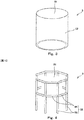
- the holding member 5 includes: a first holding portion 51, on which the inner first multilayer vacuum insulating member 3 is placed; and a second holding portion 52, around which the inner second multilayer vacuum insulating member 4 is wound.
- the holding member 5 is a container-shaped member with an opening facing the outer shell 12, and the first holding portion 51 serves as a ceiling wall and the second holding portion 52 serves as a peripheral wall.
- the first holding portion 51 serving as the ceiling wall has a circular shape
- the second holding portion 52 serving as the peripheral wall has a circular cylindrical shape.
- each of the ceiling wall and the peripheral wall may be a continuous plate as shown in Fig. 3 , or may be a plate with a large number of holes formed therein (e.g., perforated metal or expanded metal).
- the configuration of the holding member 5 can be suitably changed.
- the first holding portion 51 serving as the ceiling wall may have a polygonal shape.
- the second holding portion 52 may be formed by: a plurality of vertical rods 53 arranged along the outline of the first holding portion 51 serving as the ceiling wall; and a plurality of horizontal rods 54 coupling these vertical rods 53 together.
- the first holding portion 51 may be formed by two rods that are arranged in a cruciform, or may be formed by four or more rods that are arranged in a lattice form.
- the height of the holding member 5 is set to be less than the length of the tubular member 2.
- the holding member 5 is coupled to the tubular member 2 by a pin that is not shown.
- the inner first multilayer vacuum insulating member 3 is slightly spaced apart from the inner shell 11.
- the entire inner first multilayer vacuum insulating member 3 may be in close contact with the inner shell 11.
- the holding member 5 may be coupled to the tubular member 2 in a state where the holding member 5 is lifted from the outer shell 12.
- the inner first multilayer vacuum insulating member 3 may be fixed to the first holding portion 51, or may be simply placed on the first holding portion 51 without being fixed to the first holding portion 51.
- the inner second multilayer vacuum insulating member 4 is wound around the second holding portion 52 of the holding member 5, such that end portions of the inner second multilayer vacuum insulating member 4 overlap each other.
- the end portions of the inner second multilayer vacuum insulating member 4 are joined together by a hook-and-loop fastener, such that tensile force is exerted on the inner second multilayer vacuum insulating member 4, and by the tensile force, the inner second multilayer vacuum insulating member 4 is held on the outer peripheral surface of the tubular member 2.
- the inner second multilayer vacuum insulating member 4 may be in close contact with the inner peripheral surface of the tubular member 2, it is desirable that the inner second multilayer vacuum insulating member 4 be positioned in close proximity to the inner peripheral surface of the tubular member 2, but slightly spaced apart from the inner peripheral surface. For this reason, it is desirable that the external diameter of the second holding portion 52 serving as the peripheral wall be less than the internal diameter of the tubular member 2 by a dimension that is slightly greater than the twice of the thickness of the inner second multilayer vacuum insulating member 4. It should be noted that the position of the holding member 5 relative to the tubular member 2 is fixed by the aforementioned unshown pin (i.e., the pin that couples the holding member 5 and the tubular member 2 together).
- the length of the inner second multilayer vacuum insulating member 4 is less than the length of the tubular member 2, and the lower part of the inner peripheral surface of the tubular member 2 is exposed.
- a distance D from the lower end of the inner second multilayer vacuum insulating member 4 (i.e., one end at the outer shell 12 side) to the lower end 21 of the tubular member 2 (i.e., one end at the outer shell 12 side) is not more than 1/2 and not less than 1/6 of the length of the tubular member 2.
- the upper end of the inner second multilayer vacuum insulating member 4 (i.e., the other end at the inner shell 11 side) is in contact with the inner first multilayer vacuum insulating member 3.
- the upper end of the inner second multilayer vacuum insulating member 4 may be slightly spaced apart from the inner first multilayer vacuum insulating member 3.
- the inner first multilayer vacuum insulating member 3 and the inner second multilayer vacuum insulating member 4 may be integrated together.
- the inner second multilayer vacuum insulating member 4 which covers the inner peripheral surface of the tubular member 2, is wound around the holding member 5. Therefore, the inner second multilayer vacuum insulating member 4 can be kept in position along the inner peripheral surface of the tubular member 2 by means of the holding member 5.
- the holding member 5 includes not only the second holding portion 52, around which the inner second multilayer vacuum insulating member 4 is wound, but also the first holding portion 51, on which the inner first multilayer vacuum insulating member 3 is placed. This makes it possible to hold the inner first multilayer vacuum insulating member 3 by utilizing the holding member 5 without requiring stud bolts or the like to be provided on the inner shell 11.
- the holding member 5 is container-shaped. This makes it possible to simplify the shape of the holding member 5.
- the multilayer vacuum insulating members tend to allow heat to be readily transferred therethrough in a direction orthogonal to the thickness direction (multilayer-stacking direction). Meanwhile, since the thermal conductivity of the tubular member 2 is low, a temperature gradient is formed in the tubular member 2, in which the temperature gradually decreases from the lower end at the outer shell 12 side toward the upper end at the inner shell 11 side. In such a configuration, if the inner second multilayer vacuum insulating member 4 extends to the immediate vicinity of the outer shell 12, the inner second multilayer vacuum insulating member 4 acts as a detouring path for heat, through which heat is transferred from the lower part to the upper part of the tubular member 2 in a manner to detour the middle part of the tubular member 2.
- the inner peripheral surface of the tubular member 2 can be covered over a sufficient area, and the inner second multilayer vacuum insulating member 4 can be effectively suppressed from acting as a detouring path for heat, through which heat is transferred in a manner to detour the middle part of the tubular member 2.
- the first member and the second member of the present invention need not be the inner shell 11 and the outer shell 12 of the double-shell tank 1.
- the first member may be a low-temperature plate that protrudes from the inner shell 11, and the second member may be a high-temperature plate that protrudes from the outer shell 12 in a manner to face the low-temperature plate.
- each tubular member 2 need not be in contact with the second member, but may be spaced apart from the second member. Moreover, each tubular member 2 need not be made of a material whose thermal conductivity at ordinary temperatures is lower than 1 W/m•K. In a case where thermal conduction by the tubular member 2 is low (e.g., a case where the length of the tubular member 2 is great), the tubular member 2 may be made of a metal with high thermal conductivity.
- the holding member 5 need not include the first holding portion 51.
- the inner first multilayer vacuum insulating member 3 may be held by utilizing stud bolts provided on the inner shell 11.
- the inner second multilayer vacuum insulating member 4 may entirely cover the inner peripheral surface of the tubular member 2.
- the present invention is applicable not only to tanks but also to other various structures.
Landscapes
- Engineering & Computer Science (AREA)
- General Engineering & Computer Science (AREA)
- Mechanical Engineering (AREA)
- Physics & Mathematics (AREA)
- Thermal Sciences (AREA)
- Filling Or Discharging Of Gas Storage Vessels (AREA)
- Thermal Insulation (AREA)
Applications Claiming Priority (2)
| Application Number | Priority Date | Filing Date | Title |
|---|---|---|---|
| JP2015212733A JP6641155B2 (ja) | 2015-10-29 | 2015-10-29 | 真空断熱構造 |
| PCT/JP2016/080962 WO2017073428A1 (ja) | 2015-10-29 | 2016-10-19 | 真空断熱構造 |
Publications (3)
| Publication Number | Publication Date |
|---|---|
| EP3369984A1 true EP3369984A1 (de) | 2018-09-05 |
| EP3369984A4 EP3369984A4 (de) | 2019-03-13 |
| EP3369984B1 EP3369984B1 (de) | 2020-03-18 |
Family
ID=58630134
Family Applications (1)
| Application Number | Title | Priority Date | Filing Date |
|---|---|---|---|
| EP16859658.3A Active EP3369984B1 (de) | 2015-10-29 | 2016-10-19 | Vakuumwärmeisolierungsstruktur |
Country Status (5)
| Country | Link |
|---|---|
| EP (1) | EP3369984B1 (de) |
| JP (1) | JP6641155B2 (de) |
| KR (1) | KR102451628B1 (de) |
| CN (1) | CN108139027B (de) |
| WO (1) | WO2017073428A1 (de) |
Families Citing this family (3)
| Publication number | Priority date | Publication date | Assignee | Title |
|---|---|---|---|---|
| JP7387955B2 (ja) * | 2018-08-20 | 2023-11-29 | トーヨーカネツ株式会社 | 断熱床構造 |
| KR102315489B1 (ko) | 2020-09-01 | 2021-10-21 | 에스탱크엔지니어링(주) | 액화수소 저장탱크 |
| WO2023096030A1 (ko) * | 2021-11-24 | 2023-06-01 | 하이리움산업(주) | 극저온 유체 저장탱크의 내외조 연결부 서포트 시스템 및 이를 적용한 극저온 유체 저장탱크 |
Family Cites Families (8)
| Publication number | Priority date | Publication date | Assignee | Title |
|---|---|---|---|---|
| JPS63198899U (de) * | 1987-06-11 | 1988-12-21 | ||
| JP3428748B2 (ja) * | 1994-11-16 | 2003-07-22 | 株式会社アイ・エイチ・アイ マリンユナイテッド | 液体運搬船用自立角型タンク |
| CN2634259Y (zh) | 2003-07-09 | 2004-08-18 | 兰州理工大学 | 液化天然气贮罐内支承结构 |
| CN102305347B (zh) * | 2011-05-24 | 2012-11-21 | 张家港圣汇气体化工装备有限公司 | 高真空多层绝热深冷双壳球形储罐 |
| JP6186122B2 (ja) * | 2012-10-04 | 2017-08-23 | エア・ウォーター・プラントエンジニアリング株式会社 | 低温用真空断熱容器 |
| JP6387528B2 (ja) * | 2013-03-01 | 2018-09-12 | パナソニックIpマネジメント株式会社 | 断熱容器および断熱構造体 |
| CN105102316B (zh) * | 2013-04-23 | 2017-03-08 | 川崎重工业株式会社 | 船舶用储罐的支持结构以及液化气体运输船 |
| KR20150001585A (ko) * | 2013-06-26 | 2015-01-06 | (주)대창솔루션 | 초저온 단열 저장 탱크 |
-
2015
- 2015-10-29 JP JP2015212733A patent/JP6641155B2/ja active Active
-
2016
- 2016-10-19 WO PCT/JP2016/080962 patent/WO2017073428A1/ja not_active Ceased
- 2016-10-19 KR KR1020187013626A patent/KR102451628B1/ko active Active
- 2016-10-19 EP EP16859658.3A patent/EP3369984B1/de active Active
- 2016-10-19 CN CN201680062517.0A patent/CN108139027B/zh active Active
Also Published As
| Publication number | Publication date |
|---|---|
| JP2017082931A (ja) | 2017-05-18 |
| KR20180077184A (ko) | 2018-07-06 |
| EP3369984A4 (de) | 2019-03-13 |
| WO2017073428A1 (ja) | 2017-05-04 |
| CN108139027B (zh) | 2020-01-03 |
| KR102451628B1 (ko) | 2022-10-06 |
| EP3369984B1 (de) | 2020-03-18 |
| JP6641155B2 (ja) | 2020-02-05 |
| CN108139027A (zh) | 2018-06-08 |
Similar Documents
| Publication | Publication Date | Title |
|---|---|---|
| EP3369984B1 (de) | Vakuumwärmeisolierungsstruktur | |
| JP6134211B2 (ja) | 二重殻タンクおよび液化ガス運搬船 | |
| JP6220164B2 (ja) | 二重殻タンクおよび液化ガス運搬船 | |
| JP6186122B2 (ja) | 低温用真空断熱容器 | |
| EP3366568B1 (de) | Doppelwandiger tank für ein schiff sowie ein schiff | |
| JP2018034777A (ja) | トロイダル支持構造 | |
| US20180283769A1 (en) | Cryostat arrangement comprising a neck tube having a supporting structure and an outer tube surrounding the supporting structure to reduce the cryogen consumption | |
| US20160230932A1 (en) | Low heat loss cryogenic fluid storage equipment using multilayered cylindrical support | |
| JP2015060865A5 (de) | ||
| EP3336405B1 (de) | Wärmeisolierungsstruktur | |
| JP2015155732A (ja) | 液化ガスタンクおよび液化ガス運搬船 | |
| KR101625639B1 (ko) | 초저온 액체 저장 구조물 | |
| WO2015072348A1 (ja) | 低温タンク | |
| KR101384704B1 (ko) | 극저온 액체 이송용 진공 이중관 스패이서 | |
| KR101945895B1 (ko) | 화물창의 방벽 및 그 설치방법 | |
| JP7387955B2 (ja) | 断熱床構造 | |
| JP6415245B2 (ja) | 保温構造及びその使用方法 | |
| JP5976704B2 (ja) | 冷却装置 | |
| JP5666819B2 (ja) | フロアパネル | |
| JP2010032001A (ja) | 縦置二重殻円筒形低温貯槽の外槽構造 | |
| JP2008249093A (ja) | 配管保護カバー | |
| JP2011126549A (ja) | 断熱水槽用パネル構造体及び断熱水槽 | |
| JP2017087878A (ja) | 支持構造 | |
| JP2012057802A (ja) | 低温流体用貯蔵タンク | |
| JPH0510900U (ja) | 低温容器 |
Legal Events
| Date | Code | Title | Description |
|---|---|---|---|
| STAA | Information on the status of an ep patent application or granted ep patent |
Free format text: STATUS: THE INTERNATIONAL PUBLICATION HAS BEEN MADE |
|
| PUAI | Public reference made under article 153(3) epc to a published international application that has entered the european phase |
Free format text: ORIGINAL CODE: 0009012 |
|
| STAA | Information on the status of an ep patent application or granted ep patent |
Free format text: STATUS: REQUEST FOR EXAMINATION WAS MADE |
|
| 17P | Request for examination filed |
Effective date: 20180529 |
|
| AK | Designated contracting states |
Kind code of ref document: A1 Designated state(s): AL AT BE BG CH CY CZ DE DK EE ES FI FR GB GR HR HU IE IS IT LI LT LU LV MC MK MT NL NO PL PT RO RS SE SI SK SM TR |
|
| AX | Request for extension of the european patent |
Extension state: BA ME |
|
| DAV | Request for validation of the european patent (deleted) | ||
| DAX | Request for extension of the european patent (deleted) | ||
| A4 | Supplementary search report drawn up and despatched |
Effective date: 20190212 |
|
| RIC1 | Information provided on ipc code assigned before grant |
Ipc: F17C 3/08 20060101AFI20190206BHEP Ipc: F16L 59/065 20060101ALI20190206BHEP |
|
| GRAP | Despatch of communication of intention to grant a patent |
Free format text: ORIGINAL CODE: EPIDOSNIGR1 |
|
| STAA | Information on the status of an ep patent application or granted ep patent |
Free format text: STATUS: GRANT OF PATENT IS INTENDED |
|
| INTG | Intention to grant announced |
Effective date: 20190927 |
|
| GRAS | Grant fee paid |
Free format text: ORIGINAL CODE: EPIDOSNIGR3 |
|
| GRAA | (expected) grant |
Free format text: ORIGINAL CODE: 0009210 |
|
| STAA | Information on the status of an ep patent application or granted ep patent |
Free format text: STATUS: THE PATENT HAS BEEN GRANTED |
|
| AK | Designated contracting states |
Kind code of ref document: B1 Designated state(s): AL AT BE BG CH CY CZ DE DK EE ES FI FR GB GR HR HU IE IS IT LI LT LU LV MC MK MT NL NO PL PT RO RS SE SI SK SM TR |
|
| REG | Reference to a national code |
Ref country code: GB Ref legal event code: FG4D |
|
| REG | Reference to a national code |
Ref country code: DE Ref legal event code: R096 Ref document number: 602016032294 Country of ref document: DE |
|
| REG | Reference to a national code |
Ref country code: AT Ref legal event code: REF Ref document number: 1246296 Country of ref document: AT Kind code of ref document: T Effective date: 20200415 Ref country code: IE Ref legal event code: FG4D |
|
| REG | Reference to a national code |
Ref country code: NO Ref legal event code: T2 Effective date: 20200318 |
|
| PG25 | Lapsed in a contracting state [announced via postgrant information from national office to epo] |
Ref country code: FI Free format text: LAPSE BECAUSE OF FAILURE TO SUBMIT A TRANSLATION OF THE DESCRIPTION OR TO PAY THE FEE WITHIN THE PRESCRIBED TIME-LIMIT Effective date: 20200318 Ref country code: RS Free format text: LAPSE BECAUSE OF FAILURE TO SUBMIT A TRANSLATION OF THE DESCRIPTION OR TO PAY THE FEE WITHIN THE PRESCRIBED TIME-LIMIT Effective date: 20200318 |
|
| REG | Reference to a national code |
Ref country code: NL Ref legal event code: MP Effective date: 20200318 |
|
| PG25 | Lapsed in a contracting state [announced via postgrant information from national office to epo] |
Ref country code: BG Free format text: LAPSE BECAUSE OF FAILURE TO SUBMIT A TRANSLATION OF THE DESCRIPTION OR TO PAY THE FEE WITHIN THE PRESCRIBED TIME-LIMIT Effective date: 20200618 Ref country code: HR Free format text: LAPSE BECAUSE OF FAILURE TO SUBMIT A TRANSLATION OF THE DESCRIPTION OR TO PAY THE FEE WITHIN THE PRESCRIBED TIME-LIMIT Effective date: 20200318 Ref country code: GR Free format text: LAPSE BECAUSE OF FAILURE TO SUBMIT A TRANSLATION OF THE DESCRIPTION OR TO PAY THE FEE WITHIN THE PRESCRIBED TIME-LIMIT Effective date: 20200619 Ref country code: LV Free format text: LAPSE BECAUSE OF FAILURE TO SUBMIT A TRANSLATION OF THE DESCRIPTION OR TO PAY THE FEE WITHIN THE PRESCRIBED TIME-LIMIT Effective date: 20200318 Ref country code: SE Free format text: LAPSE BECAUSE OF FAILURE TO SUBMIT A TRANSLATION OF THE DESCRIPTION OR TO PAY THE FEE WITHIN THE PRESCRIBED TIME-LIMIT Effective date: 20200318 |
|
| REG | Reference to a national code |
Ref country code: LT Ref legal event code: MG4D |
|
| PG25 | Lapsed in a contracting state [announced via postgrant information from national office to epo] |
Ref country code: NL Free format text: LAPSE BECAUSE OF FAILURE TO SUBMIT A TRANSLATION OF THE DESCRIPTION OR TO PAY THE FEE WITHIN THE PRESCRIBED TIME-LIMIT Effective date: 20200318 |
|
| PG25 | Lapsed in a contracting state [announced via postgrant information from national office to epo] |
Ref country code: CZ Free format text: LAPSE BECAUSE OF FAILURE TO SUBMIT A TRANSLATION OF THE DESCRIPTION OR TO PAY THE FEE WITHIN THE PRESCRIBED TIME-LIMIT Effective date: 20200318 Ref country code: RO Free format text: LAPSE BECAUSE OF FAILURE TO SUBMIT A TRANSLATION OF THE DESCRIPTION OR TO PAY THE FEE WITHIN THE PRESCRIBED TIME-LIMIT Effective date: 20200318 Ref country code: LT Free format text: LAPSE BECAUSE OF FAILURE TO SUBMIT A TRANSLATION OF THE DESCRIPTION OR TO PAY THE FEE WITHIN THE PRESCRIBED TIME-LIMIT Effective date: 20200318 Ref country code: SM Free format text: LAPSE BECAUSE OF FAILURE TO SUBMIT A TRANSLATION OF THE DESCRIPTION OR TO PAY THE FEE WITHIN THE PRESCRIBED TIME-LIMIT Effective date: 20200318 Ref country code: SK Free format text: LAPSE BECAUSE OF FAILURE TO SUBMIT A TRANSLATION OF THE DESCRIPTION OR TO PAY THE FEE WITHIN THE PRESCRIBED TIME-LIMIT Effective date: 20200318 Ref country code: EE Free format text: LAPSE BECAUSE OF FAILURE TO SUBMIT A TRANSLATION OF THE DESCRIPTION OR TO PAY THE FEE WITHIN THE PRESCRIBED TIME-LIMIT Effective date: 20200318 Ref country code: PT Free format text: LAPSE BECAUSE OF FAILURE TO SUBMIT A TRANSLATION OF THE DESCRIPTION OR TO PAY THE FEE WITHIN THE PRESCRIBED TIME-LIMIT Effective date: 20200812 Ref country code: IS Free format text: LAPSE BECAUSE OF FAILURE TO SUBMIT A TRANSLATION OF THE DESCRIPTION OR TO PAY THE FEE WITHIN THE PRESCRIBED TIME-LIMIT Effective date: 20200718 |
|
| REG | Reference to a national code |
Ref country code: AT Ref legal event code: MK05 Ref document number: 1246296 Country of ref document: AT Kind code of ref document: T Effective date: 20200318 |
|
| REG | Reference to a national code |
Ref country code: DE Ref legal event code: R097 Ref document number: 602016032294 Country of ref document: DE |
|
| PLBE | No opposition filed within time limit |
Free format text: ORIGINAL CODE: 0009261 |
|
| STAA | Information on the status of an ep patent application or granted ep patent |
Free format text: STATUS: NO OPPOSITION FILED WITHIN TIME LIMIT |
|
| PG25 | Lapsed in a contracting state [announced via postgrant information from national office to epo] |
Ref country code: ES Free format text: LAPSE BECAUSE OF FAILURE TO SUBMIT A TRANSLATION OF THE DESCRIPTION OR TO PAY THE FEE WITHIN THE PRESCRIBED TIME-LIMIT Effective date: 20200318 Ref country code: AT Free format text: LAPSE BECAUSE OF FAILURE TO SUBMIT A TRANSLATION OF THE DESCRIPTION OR TO PAY THE FEE WITHIN THE PRESCRIBED TIME-LIMIT Effective date: 20200318 Ref country code: IT Free format text: LAPSE BECAUSE OF FAILURE TO SUBMIT A TRANSLATION OF THE DESCRIPTION OR TO PAY THE FEE WITHIN THE PRESCRIBED TIME-LIMIT Effective date: 20200318 Ref country code: DK Free format text: LAPSE BECAUSE OF FAILURE TO SUBMIT A TRANSLATION OF THE DESCRIPTION OR TO PAY THE FEE WITHIN THE PRESCRIBED TIME-LIMIT Effective date: 20200318 |
|
| 26N | No opposition filed |
Effective date: 20201221 |
|
| PG25 | Lapsed in a contracting state [announced via postgrant information from national office to epo] |
Ref country code: PL Free format text: LAPSE BECAUSE OF FAILURE TO SUBMIT A TRANSLATION OF THE DESCRIPTION OR TO PAY THE FEE WITHIN THE PRESCRIBED TIME-LIMIT Effective date: 20200318 |
|
| REG | Reference to a national code |
Ref country code: DE Ref legal event code: R119 Ref document number: 602016032294 Country of ref document: DE |
|
| PG25 | Lapsed in a contracting state [announced via postgrant information from national office to epo] |
Ref country code: SI Free format text: LAPSE BECAUSE OF FAILURE TO SUBMIT A TRANSLATION OF THE DESCRIPTION OR TO PAY THE FEE WITHIN THE PRESCRIBED TIME-LIMIT Effective date: 20200318 |
|
| REG | Reference to a national code |
Ref country code: CH Ref legal event code: PL |
|
| GBPC | Gb: european patent ceased through non-payment of renewal fee |
Effective date: 20201019 |
|
| PG25 | Lapsed in a contracting state [announced via postgrant information from national office to epo] |
Ref country code: LU Free format text: LAPSE BECAUSE OF NON-PAYMENT OF DUE FEES Effective date: 20201019 Ref country code: MC Free format text: LAPSE BECAUSE OF FAILURE TO SUBMIT A TRANSLATION OF THE DESCRIPTION OR TO PAY THE FEE WITHIN THE PRESCRIBED TIME-LIMIT Effective date: 20200318 |
|
| REG | Reference to a national code |
Ref country code: BE Ref legal event code: MM Effective date: 20201031 |
|
| PG25 | Lapsed in a contracting state [announced via postgrant information from national office to epo] |
Ref country code: DE Free format text: LAPSE BECAUSE OF NON-PAYMENT OF DUE FEES Effective date: 20210501 Ref country code: FR Free format text: LAPSE BECAUSE OF NON-PAYMENT OF DUE FEES Effective date: 20201031 |
|
| PG25 | Lapsed in a contracting state [announced via postgrant information from national office to epo] |
Ref country code: BE Free format text: LAPSE BECAUSE OF NON-PAYMENT OF DUE FEES Effective date: 20201031 Ref country code: CH Free format text: LAPSE BECAUSE OF NON-PAYMENT OF DUE FEES Effective date: 20201031 Ref country code: LI Free format text: LAPSE BECAUSE OF NON-PAYMENT OF DUE FEES Effective date: 20201031 Ref country code: GB Free format text: LAPSE BECAUSE OF NON-PAYMENT OF DUE FEES Effective date: 20201019 |
|
| PG25 | Lapsed in a contracting state [announced via postgrant information from national office to epo] |
Ref country code: IE Free format text: LAPSE BECAUSE OF NON-PAYMENT OF DUE FEES Effective date: 20201019 |
|
| PG25 | Lapsed in a contracting state [announced via postgrant information from national office to epo] |
Ref country code: TR Free format text: LAPSE BECAUSE OF FAILURE TO SUBMIT A TRANSLATION OF THE DESCRIPTION OR TO PAY THE FEE WITHIN THE PRESCRIBED TIME-LIMIT Effective date: 20200318 Ref country code: MT Free format text: LAPSE BECAUSE OF FAILURE TO SUBMIT A TRANSLATION OF THE DESCRIPTION OR TO PAY THE FEE WITHIN THE PRESCRIBED TIME-LIMIT Effective date: 20200318 Ref country code: CY Free format text: LAPSE BECAUSE OF FAILURE TO SUBMIT A TRANSLATION OF THE DESCRIPTION OR TO PAY THE FEE WITHIN THE PRESCRIBED TIME-LIMIT Effective date: 20200318 |
|
| PG25 | Lapsed in a contracting state [announced via postgrant information from national office to epo] |
Ref country code: MK Free format text: LAPSE BECAUSE OF FAILURE TO SUBMIT A TRANSLATION OF THE DESCRIPTION OR TO PAY THE FEE WITHIN THE PRESCRIBED TIME-LIMIT Effective date: 20200318 Ref country code: AL Free format text: LAPSE BECAUSE OF FAILURE TO SUBMIT A TRANSLATION OF THE DESCRIPTION OR TO PAY THE FEE WITHIN THE PRESCRIBED TIME-LIMIT Effective date: 20200318 |
|
| PGFP | Annual fee paid to national office [announced via postgrant information from national office to epo] |
Ref country code: NO Payment date: 20251009 Year of fee payment: 10 |