EP3369643A1 - Mit anderen gleichen rahmen ineinanderschiebbarer rahmen eines handwagens - Google Patents
Mit anderen gleichen rahmen ineinanderschiebbarer rahmen eines handwagens Download PDFInfo
- Publication number
- EP3369643A1 EP3369643A1 EP18157450.0A EP18157450A EP3369643A1 EP 3369643 A1 EP3369643 A1 EP 3369643A1 EP 18157450 A EP18157450 A EP 18157450A EP 3369643 A1 EP3369643 A1 EP 3369643A1
- Authority
- EP
- European Patent Office
- Prior art keywords
- frame
- trolley
- members
- nestable
- frame members
- Prior art date
- Legal status (The legal status is an assumption and is not a legal conclusion. Google has not performed a legal analysis and makes no representation as to the accuracy of the status listed.)
- Withdrawn
Links
- 230000008878 coupling Effects 0.000 claims description 6
- 238000010168 coupling process Methods 0.000 claims description 6
- 238000005859 coupling reaction Methods 0.000 claims description 6
- 230000001154 acute effect Effects 0.000 description 2
- 239000002184 metal Substances 0.000 description 2
- 235000004443 Ricinus communis Nutrition 0.000 description 1
- 239000000463 material Substances 0.000 description 1
- 229920003023 plastic Polymers 0.000 description 1
- 239000004033 plastic Substances 0.000 description 1
Images

Classifications
-
- B—PERFORMING OPERATIONS; TRANSPORTING
- B62—LAND VEHICLES FOR TRAVELLING OTHERWISE THAN ON RAILS
- B62B—HAND-PROPELLED VEHICLES, e.g. HAND CARTS OR PERAMBULATORS; SLEDGES
- B62B3/00—Hand carts having more than one axis carrying transport wheels; Steering devices therefor; Equipment therefor
- B62B3/14—Hand carts having more than one axis carrying transport wheels; Steering devices therefor; Equipment therefor characterised by provisions for nesting or stacking, e.g. shopping trolleys
- B62B3/18—Hand carts having more than one axis carrying transport wheels; Steering devices therefor; Equipment therefor characterised by provisions for nesting or stacking, e.g. shopping trolleys nestable by means of pivoted supports or support parts, e.g. baskets
- B62B3/184—Nestable roll containers
- B62B3/186—V-shaped when nested
-
- B—PERFORMING OPERATIONS; TRANSPORTING
- B62—LAND VEHICLES FOR TRAVELLING OTHERWISE THAN ON RAILS
- B62B—HAND-PROPELLED VEHICLES, e.g. HAND CARTS OR PERAMBULATORS; SLEDGES
- B62B3/00—Hand carts having more than one axis carrying transport wheels; Steering devices therefor; Equipment therefor
-
- B—PERFORMING OPERATIONS; TRANSPORTING
- B62—LAND VEHICLES FOR TRAVELLING OTHERWISE THAN ON RAILS
- B62B—HAND-PROPELLED VEHICLES, e.g. HAND CARTS OR PERAMBULATORS; SLEDGES
- B62B3/00—Hand carts having more than one axis carrying transport wheels; Steering devices therefor; Equipment therefor
- B62B3/02—Hand carts having more than one axis carrying transport wheels; Steering devices therefor; Equipment therefor involving parts being adjustable, collapsible, attachable, detachable or convertible
-
- B—PERFORMING OPERATIONS; TRANSPORTING
- B62—LAND VEHICLES FOR TRAVELLING OTHERWISE THAN ON RAILS
- B62B—HAND-PROPELLED VEHICLES, e.g. HAND CARTS OR PERAMBULATORS; SLEDGES
- B62B3/00—Hand carts having more than one axis carrying transport wheels; Steering devices therefor; Equipment therefor
- B62B3/14—Hand carts having more than one axis carrying transport wheels; Steering devices therefor; Equipment therefor characterised by provisions for nesting or stacking, e.g. shopping trolleys
- B62B3/16—Hand carts having more than one axis carrying transport wheels; Steering devices therefor; Equipment therefor characterised by provisions for nesting or stacking, e.g. shopping trolleys vertically stackable
-
- B—PERFORMING OPERATIONS; TRANSPORTING
- B62—LAND VEHICLES FOR TRAVELLING OTHERWISE THAN ON RAILS
- B62B—HAND-PROPELLED VEHICLES, e.g. HAND CARTS OR PERAMBULATORS; SLEDGES
- B62B3/00—Hand carts having more than one axis carrying transport wheels; Steering devices therefor; Equipment therefor
- B62B3/14—Hand carts having more than one axis carrying transport wheels; Steering devices therefor; Equipment therefor characterised by provisions for nesting or stacking, e.g. shopping trolleys
- B62B3/18—Hand carts having more than one axis carrying transport wheels; Steering devices therefor; Equipment therefor characterised by provisions for nesting or stacking, e.g. shopping trolleys nestable by means of pivoted supports or support parts, e.g. baskets
-
- B—PERFORMING OPERATIONS; TRANSPORTING
- B62—LAND VEHICLES FOR TRAVELLING OTHERWISE THAN ON RAILS
- B62B—HAND-PROPELLED VEHICLES, e.g. HAND CARTS OR PERAMBULATORS; SLEDGES
- B62B2203/00—Grasping, holding, supporting the objects
- B62B2203/20—Grasping, holding, supporting the objects using forks or tines
- B62B2203/28—Guiding the forks into the pallets
Definitions
- the present invention relates to a nestable trolley frame and a trolley comprising the nestable trolley frame.
- Trolleys are well known for transporting items and come in a variety of sizes and configurations to suit the particular application.
- supermarket shopping trolleys are known for retaining items while shopping and comprise a basket which is supported upon a wheeled frame.
- So-called "sack" trolleys are also well known for transporting larger items, including boxes and the like.
- a nestable trolley frame comprising two first frame members which converge toward each other in a direction which is from a first end of the frame to a second end of the frame, and two second frame members which converge toward each other in a direction which is from the second end of the frame to the first end of the frame, wherein the first frame members are separately coupled at a distal end thereof to a distal end of a respective second frame member, and wherein the second frame members are coupled together at a proximal end thereof, such that the trolley frame is permitted to nest within a further identical frame by passing the first/second end of the frame into the second/first end of the further frame, respectively.
- first frame members and the second frame members extend in a common plane.
- the second frame members preferably extend between the first frame members forming a substantially W-shape or M-shape trolley frame.
- first and second frame members comprise substantially linear members.
- first and second frame members may comprise arcuate members.
- the coupling between the first frame members and the respective second frame members form a respective apex in the trolley frame proximate the second end of the frame.
- the coupling between the second frame members preferably form an apex in the trolley frame proximate the first end of the frame.
- the trolley frame comprises a wheel disposed at an underside of thereof, proximate the first end and second end of the trolley.
- the trolley comprises a wheel disposed at a proximal end of each of the first frame members and a wheel disposed at an underside of the coupling between the first and second frame members.
- the wheels are coupled to the trolley frame via a respective mounting which extends between the frame and the respective wheel.
- the frame may comprise at least two channels which extend parallel to each other within a common plane.
- Each of the channels may define a through-hole having a longitudinal axis which substantially bisects an angle defined between the two coupled frame members.
- the channels may extend within a common plane with the coupled frame members and each of the channels may comprise a first connecting portion and second connecting portion arranged substantially in parallel, and being spaced from each other.
- Each connecting portion may be arranged to couple the respective frame members at their distal ends and the channels may be adapted to receive transporting means for lifting the trolley frame.
- a trolley comprising a nestable trolley frame of the first aspect and a support base disposed upon the frame for receiving items.
- the support base is hingedly coupled to the frame.
- the base may be hingedly coupled to the base proximate the first or second end thereof, such that the base can pivot with respect to the frame between a first configuration in which the base extends substantially parallel with a plane of the trolley frame for supporting items, and a second configuration in which the base extends substantially transverse to the trolley frame for nesting with further trolleys during storage.
- the trolley further comprises at least one side wall which cooperates with the base to form a trolley enclosure for receiving items.
- the trolley further comprises a handle for permitting a user to maneouvre the trolley.
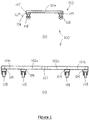
- the trolley frame 100 defines a support for supporting items (not shown) placed thereon and may be formed of a metal or rigid plastics material, for example.
- the frame 100 comprises two substantially linear first frame members 101a, 101b and two substantially linear second frame members 102a, 102b, however, the skilled reader will recognise that the frame members 101, 102 may alternatively comprise arcuate members.
- the first and second frame members 101, 102 are orientated to extend within a common plane to provide a substantially planar support frame 100, and the first frame members 101 are further orientated to converge toward each other in a direction which is from a first end 103 of the frame 100 to a second end 104 of the frame 100.
- the two second frame members 102 are also orientated to converge toward each other, but in a direction which is from the second end 104 of the frame 100 to the first end 103 of the frame 103.
- the second frame members 102 are disposed between the first frame members 101 and the first frame members 101 are separately coupled at a distal end thereof to a distal end of a respective second frame member 102.
- the second frame members 102 are coupled together at a proximal end thereof such that the frame 100 comprises a substantially "M" or "W" shape.
- the first frame member 101a, 101b and the respective adjoining second frame member 102a, 102b form an acute angle therebetween and thus form a respective apex 105, 106 proximate the second end 104 of the frame 100.
- the second frame members 102a, 102b define an acute angle therebetween and thus a further frame apex 107 disposed proximate the first end 103 of the frame 100.
- the frame 100 may instead comprise a single-piece frame member which is shaped, namely turned, to form the respective apices and thus the first and second frame members 101, 102.
- the trolley frame 100 further comprises a plurality of wheels 108 disposed at one planar side of the frame 100, namely an underside thereof.
- the wheels 108 may comprise castor wheels for example, and are secured to the frame members 101, 102 via a respective mounting 109, which may comprise a bracket or plate rigidly secured to the underside of the frame 100 at the proximal end of each of the first frame members 101, and also at the apices 105, 106 disposed proximate the second end 104 of the frame 100.
- the frame members 101, 102 forming the apices 105, 106 are further coupled to the respective mounting 109, which also acts to maintain a rigid configuration and orientation of the first and second members 101, 102relative to each other.
- the wheels 108 permit the frame 100 to be manoeuvred easily while the particular frame shape permits the frame 100 to nest within a further identical frame such that the nested frames can occupy a reduced floor space when not required.
- the trolley frame 100 is permitted to nest within a further identical frame by passing the first/second end 103/104 of the frame 100 into the second/first 104/103 end of the further frame, respectively.
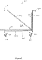
- the trolley 200 comprises the nestable trolley frame 100 described above and as such the features of the trolley frame 100 have been referenced with the same numerals.
- the trolley 200 further comprises a support base 201 which may comprise a continuous, planar support surface or a planar mesh for example, for supporting items placed thereon.
- the base 201 is hingedly coupled to the first 103 or second end 104 of the trolley frame 100 via a hinge (not shown) such that the base 201 can pivot with respect to the trolley frame 100 between a first configuration in which the base 201 extends substantially parallel with the plane of the trolley frame 100 for supporting items, and a second configuration in which the base 201 extends substantially transverse to the trolley frame 100 for nesting with further trolleys during storage.
- the trolley 200 may further comprise at least one side wall 202 which cooperates with the base 201 to form an enclosure 203 for retaining items placed therein.
- the wall 202 is disposed along the side of the base 201 about which the base 201 can pivot, however the skilled reader will recognise that the enclosure may comprise walls 202 which extend from alternative an/or additional sides of the base 201.
- the trolley 200 further comprises a handle frame 204 which extends from the first 103 or second end 104 of the frame 100, upwardly away from the trolley frame 100 and which terminates at a handle 205 which enables a user to suitably manoeuvre the trolley 200.
- the base 201 is configured to a lowered configuration so that it extends over the trolley frame 100 for receiving items placed thereon.
- the base 201 is reconfigured to the second configuration so that it extends substantially vertically, parallel to the wall 203, and the trolley 200 is then manoeuvred using the handle 205 so that the first/second end 103/104 of the trolley frame 100 passes into the second/first end 104/103 of the frame 100 of a further trolley.
- the first and second members 101, 102 of the trolley frame 100 of each trolley 200 extend adjacent each other in near contact therewith and thus occupy a reduced the floor space compared with two separated trolleys.
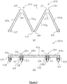
- a trolley frame 300 which may comprise at least two channels 310, 320 which extend parallel to each other within a common plane.
- each of the channels 310, 320 may define a through-hole 316, 326 having a longitudinal axis which substantially bisects an angle defined between the two coupled frame members 101a and 102a or 101b and 102b.
- the channels 310, 320, 316, 326 may extend within a common plane with the coupled frame members 101a, 102a, 101b, 102b and each of the channels 310, 320 may comprise a first connecting portion 313, 323 and second connecting portion 314, 324 arranged substantially in parallel, and being spaced from each other.
- Each of the channels 310, 320, 316, 326 may further comprise a first end 312, 322 which may be orientated toward the first end 103 of the frame 300 and second end 311, 321 which may be orientated toward the second end 104 of the frame 300.
- Each connecting portion 313, 314, 323, 324 may be arranged to couple the respective frame members 101a and 102a or 101b and 102b at their distal ends.
- the portions 313, 314, 323, 324 may comprise metal plates (not shown) which may be welded, brazed or bolted to the respective frame members.
- the frame 300 may comprise all of the features mentioned in relation to the frame 200 and may also be embodied in the trolley 200.
- the channels 310, 320, 316, 326 may also be adapted to receive transporting means (not shown) for lifting the trolley frame 300, and in particular to receive a fork of the forklift so that the frame 300 or the trolley incorporating such a frame may be lifted and moved to a different location.
- each of the forks of the forklift may be inserted into the respective channels 310, 320, 316, 326 via the second ends 311, 321 thereof so the loaded frame 300 or trolley incorporating such a frame may be lifted and moved by the forklift.
- An additional support element such as a transverse beam connecting the proximal ends of the frame members 101a, 102a, 101b, 102b may be disposed within the frame 300 for providing additional support region to a portion of the forks of the forklift so that nesting of the frame 300 with further frames 300 is not prevented.
- a portion of each of the forks of the forklift may alternatively rest against a respective portion of any of the base 201, wall 202 or handle frame 204 disposed proximate to the first end 103 of the frame 300.
Landscapes
- Engineering & Computer Science (AREA)
- Chemical & Material Sciences (AREA)
- Combustion & Propulsion (AREA)
- Transportation (AREA)
- Mechanical Engineering (AREA)
- Handcart (AREA)
Applications Claiming Priority (2)
| Application Number | Priority Date | Filing Date | Title |
|---|---|---|---|
| GBGB1703327.5A GB201703327D0 (en) | 2017-03-01 | 2017-03-01 | A nestable trolley frame |
| GB1708017.7A GB2560206A (en) | 2017-03-01 | 2017-05-18 | A nestable trolley frame |
Publications (1)
| Publication Number | Publication Date |
|---|---|
| EP3369643A1 true EP3369643A1 (de) | 2018-09-05 |
Family
ID=58544385
Family Applications (1)
| Application Number | Title | Priority Date | Filing Date |
|---|---|---|---|
| EP18157450.0A Withdrawn EP3369643A1 (de) | 2017-03-01 | 2018-02-19 | Mit anderen gleichen rahmen ineinanderschiebbarer rahmen eines handwagens |
Country Status (2)
| Country | Link |
|---|---|
| EP (1) | EP3369643A1 (de) |
| GB (2) | GB201703327D0 (de) |
Citations (4)
| Publication number | Priority date | Publication date | Assignee | Title |
|---|---|---|---|---|
| US2827302A (en) * | 1956-09-12 | 1958-03-18 | Western Electric Co | Pallet trucks |
| US2992010A (en) * | 1959-12-21 | 1961-07-11 | Raymond M Sides | Grocery carts |
| US3462166A (en) * | 1966-07-26 | 1969-08-19 | Mann Mobel Und Einrichtungshau | Transport device for furniture |
| EP0048135A2 (de) * | 1980-09-12 | 1982-03-24 | McKinnon, Crerand | Lastwagen |
Family Cites Families (6)
| Publication number | Priority date | Publication date | Assignee | Title |
|---|---|---|---|---|
| GB1382806A (en) * | 1971-02-05 | 1975-02-05 | Sieder J S | Wheeled trolleys |
| GB1429834A (en) * | 1972-03-25 | 1976-03-31 | Stakapal Ltd | Trolleys |
| ZA816294B (en) * | 1980-09-12 | 1982-08-25 | Crerand Mckinnon | Load-carrying trolleys |
| FI75530C (fi) * | 1986-10-23 | 1988-07-11 | Ostosvaunuhuolto Oy | Transportvagn. |
| FR2734776B1 (fr) * | 1995-05-29 | 1997-07-04 | Roland Leorat | Chariot d'achat pour magasins a libre service |
| JP2007099376A (ja) * | 2005-10-07 | 2007-04-19 | Fuso Kinzoku Kogyo Kk | コンテナ |
-
2017
- 2017-03-01 GB GBGB1703327.5A patent/GB201703327D0/en not_active Ceased
- 2017-05-18 GB GB1708017.7A patent/GB2560206A/en not_active Withdrawn
-
2018
- 2018-02-19 EP EP18157450.0A patent/EP3369643A1/de not_active Withdrawn
Patent Citations (4)
| Publication number | Priority date | Publication date | Assignee | Title |
|---|---|---|---|---|
| US2827302A (en) * | 1956-09-12 | 1958-03-18 | Western Electric Co | Pallet trucks |
| US2992010A (en) * | 1959-12-21 | 1961-07-11 | Raymond M Sides | Grocery carts |
| US3462166A (en) * | 1966-07-26 | 1969-08-19 | Mann Mobel Und Einrichtungshau | Transport device for furniture |
| EP0048135A2 (de) * | 1980-09-12 | 1982-03-24 | McKinnon, Crerand | Lastwagen |
Also Published As
| Publication number | Publication date |
|---|---|
| GB2560206A (en) | 2018-09-05 |
| GB201703327D0 (en) | 2017-04-12 |
| GB201708017D0 (en) | 2017-07-05 |
Similar Documents
| Publication | Publication Date | Title |
|---|---|---|
| FI75530C (fi) | Transportvagn. | |
| US6793223B2 (en) | Convertible stocking cart | |
| FI85124C (fi) | Skottkaerra. | |
| US5785328A (en) | Stackable cart assembly | |
| US8167322B2 (en) | Stable shop and field welding cart | |
| CN105163998A (zh) | 购物手推车 | |
| US20120112423A1 (en) | Handcart | |
| PL171943B1 (pl) | Wózek z samonastawnymi kólkami skretnymi PL PL PL | |
| US20120074665A1 (en) | Handcart | |
| US11958522B2 (en) | Stiffened nesting shopping cart | |
| JP2022031570A (ja) | 運搬台車 | |
| US7207578B2 (en) | Dolly for dock plates | |
| EP3369643A1 (de) | Mit anderen gleichen rahmen ineinanderschiebbarer rahmen eines handwagens | |
| US20080084035A1 (en) | Cart with caster lift | |
| US3706461A (en) | Wheelbarrow assembly | |
| JP6352518B1 (ja) | 台車、これに使用される台車本体および操作具 | |
| US11110946B2 (en) | Handcart | |
| KR20090000250U (ko) | 무게 중심 축을 개량한 수직 적재식 손수레 | |
| JP6994249B2 (ja) | 台車、これに使用される台車本体および操作具 | |
| JP6980828B2 (ja) | 運搬台車用取っ手及び運搬台車 | |
| JP7611624B1 (ja) | 台車システム | |
| KR100775672B1 (ko) | 중첩식 이동대차 | |
| JP2010012847A (ja) | ケース運搬用台車 | |
| JP7411976B2 (ja) | 手押ユニットおよび運搬台車 | |
| KR200407564Y1 (ko) | 중량물 적재테이블 |
Legal Events
| Date | Code | Title | Description |
|---|---|---|---|
| PUAI | Public reference made under article 153(3) epc to a published international application that has entered the european phase |
Free format text: ORIGINAL CODE: 0009012 |
|
| AK | Designated contracting states |
Kind code of ref document: A1 Designated state(s): AL AT BE BG CH CY CZ DE DK EE ES FI FR GB GR HR HU IE IS IT LI LT LU LV MC MK MT NL NO PL PT RO RS SE SI SK SM TR |
|
| AX | Request for extension of the european patent |
Extension state: BA ME |
|
| STAA | Information on the status of an ep patent application or granted ep patent |
Free format text: STATUS: THE APPLICATION IS DEEMED TO BE WITHDRAWN |
|
| 18D | Application deemed to be withdrawn |
Effective date: 20190306 |