EP3369245B1 - Kameraanordnung mit optischer bildstabilisierung - Google Patents
Kameraanordnung mit optischer bildstabilisierung Download PDFInfo
- Publication number
- EP3369245B1 EP3369245B1 EP16795404.9A EP16795404A EP3369245B1 EP 3369245 B1 EP3369245 B1 EP 3369245B1 EP 16795404 A EP16795404 A EP 16795404A EP 3369245 B1 EP3369245 B1 EP 3369245B1
- Authority
- EP
- European Patent Office
- Prior art keywords
- image sensor
- actuator wires
- support structure
- camera assembly
- light
- Prior art date
- Legal status (The legal status is an assumption and is not a legal conclusion. Google has not performed a legal analysis and makes no representation as to the accuracy of the status listed.)
- Active
Links
Images


Classifications
-
- H—ELECTRICITY
- H04—ELECTRIC COMMUNICATION TECHNIQUE
- H04N—PICTORIAL COMMUNICATION, e.g. TELEVISION
- H04N23/00—Cameras or camera modules comprising electronic image sensors; Control thereof
- H04N23/50—Constructional details
- H04N23/54—Mounting of pick-up tubes, electronic image sensors, deviation or focusing coils
-
- F—MECHANICAL ENGINEERING; LIGHTING; HEATING; WEAPONS; BLASTING
- F03—MACHINES OR ENGINES FOR LIQUIDS; WIND, SPRING, OR WEIGHT MOTORS; PRODUCING MECHANICAL POWER OR A REACTIVE PROPULSIVE THRUST, NOT OTHERWISE PROVIDED FOR
- F03G—SPRING, WEIGHT, INERTIA OR LIKE MOTORS; MECHANICAL-POWER PRODUCING DEVICES OR MECHANISMS, NOT OTHERWISE PROVIDED FOR OR USING ENERGY SOURCES NOT OTHERWISE PROVIDED FOR
- F03G7/00—Mechanical-power-producing mechanisms, not otherwise provided for or using energy sources not otherwise provided for
- F03G7/06—Mechanical-power-producing mechanisms, not otherwise provided for or using energy sources not otherwise provided for using expansion or contraction of bodies due to heating, cooling, moistening, drying or the like
- F03G7/061—Mechanical-power-producing mechanisms, not otherwise provided for or using energy sources not otherwise provided for using expansion or contraction of bodies due to heating, cooling, moistening, drying or the like characterised by the actuating element
- F03G7/0614—Mechanical-power-producing mechanisms, not otherwise provided for or using energy sources not otherwise provided for using expansion or contraction of bodies due to heating, cooling, moistening, drying or the like characterised by the actuating element using shape memory elements
-
- G—PHYSICS
- G02—OPTICS
- G02B—OPTICAL ELEMENTS, SYSTEMS OR APPARATUS
- G02B27/00—Optical systems or apparatus not provided for by any of the groups G02B1/00 - G02B26/00, G02B30/00
- G02B27/64—Imaging systems using optical elements for stabilisation of the lateral and angular position of the image
- G02B27/646—Imaging systems using optical elements for stabilisation of the lateral and angular position of the image compensating for small deviations, e.g. due to vibration or shake
-
- H—ELECTRICITY
- H04—ELECTRIC COMMUNICATION TECHNIQUE
- H04N—PICTORIAL COMMUNICATION, e.g. TELEVISION
- H04N23/00—Cameras or camera modules comprising electronic image sensors; Control thereof
- H04N23/60—Control of cameras or camera modules
- H04N23/68—Control of cameras or camera modules for stable pick-up of the scene, e.g. compensating for camera body vibrations
- H04N23/682—Vibration or motion blur correction
- H04N23/685—Vibration or motion blur correction performed by mechanical compensation
- H04N23/687—Vibration or motion blur correction performed by mechanical compensation by shifting the lens or sensor position
Definitions
- the present invention relates to camera assemblies in which optical image stabilisation (OIS) is provided.
- OIS optical image stabilisation
- OIS In a camera, the purpose of OIS is to compensate for camera shake, that is vibration of the camera, typically caused by user hand movement, that degrades the quality of the image captured by the image sensor.
- Mechanical OIS typically involves detecting the vibration by a vibration sensor such as a gyroscope sensor, and controlling, on the basis of the detected vibration, an actuator arrangement that adjusts the camera apparatus to compensate for the vibration.
- a vibration sensor such as a gyroscope sensor
- actuator arrangement that adjusts the camera apparatus to compensate for the vibration.
- a number of actuator arrangements employing mechanical OIS techniques are known and applied successfully in relatively large camera apparatuses, such as digital still cameras, but are difficult to miniaturise.
- Cameras have become very common in a wide range of portable electronic equipment, for example mobile telephones and tablet computers, and in many such applications miniaturisation of the camera is important.
- the very tight packaging of components in miniature camera apparatuses presents great difficulties in adding OIS actuators within the desired package.
- the camera unit comprising an image sensor and a lens system for focussing an image on the image sensor is tilted relative to the support structure of the camera assembly around two notional axes that are perpendicular to each other and to the light-sensitive region of the image sensor.
- OIS-tilt Such a type of OIS will be referred to herein as "OIS-tilt”.
- WO-2010/029316 and WO-2010/089529 each disclose camera assemblies of this type in which a plurality of shape memory alloy (SMA) actuator wires are arranged to drive tilting of the camera unit. In such a camera, sufficient clearance needs to be provided to allow for tilting of the entire camera unit.
- SMA shape memory alloy
- OIS-lens shift In another type of mechanical OIS, a lens assembly is moved orthogonal to the optical axis of the at least one lens. Such a type of OIS will be referred to herein as "OIS-lens shift". OIS-lens shift has the potential to reduce the size of the overall package for the camera as compared to OIS-tilt because only the lens assembly is moved and the lateral movement thereof requires less clearance than tilting the entire camera.
- WO-2013/175197 and WO-2014/083318 each disclose camera assemblies of this type in which a plurality of SMA actuator wires are arranged to drive movement of the lens arrangement.
- WO-2013/175197 and WO-2014/083318 use different suspension systems for the lens assembly, utilising beams and ball bearings, respectively.
- the first aspect of the present invention is concerned with an alternative camera assembly that can provide OIS using SMA actuator wires.
- a camera assembly as claimed in claim 1.
- the first aspect of the present invention therefore provides relative movement between the image sensor and a lens assembly provided in a camera in which the camera assembly may be incorporated. That relative movement provides OIS in a similar manner to OIS-lens shift. As the movement is driven by plural SMA actuator wires, this achieves similar advantages to those described in WO-2013/175197 and WO-2014/083318 .
- the use of SMA actuator wires facilitates miniaturisation compared to other types of actuator, and the dimension along the optical axis may be reduced compared to OIS-tilt arrangements.
- the first aspect of the present invention differs from OIS-lens shift in that the image sensor, rather than the lens assembly, is moved laterally. This provides a number of advantages as follows.
- Movement of the image sensor is typically more convenient, as the image sensor is a smaller component than the lens assembly. This facilitates miniaturisation of the camera.
- provision of OIS by movement of the image sensor can improve the performance of the OIS compared to OIS-lens shift.
- the major component of shake-induced image blur is in the plane perpendicular to the optical axis
- rotational blur can also be caused by rotation around the optical axis.
- a counter-rotation of the lens assembly has no effect on this rotation induced blur, as the lens assembly is typically rotationally symmetric around the optical axis.
- the first aspect of the present invention allows rotational image stabilisation also to be provided.
- the image sensor may be supported on the support structure in a manner further allowing rotation of the image sensor about an axis orthogonal to the light-sensitive region, and the plural shape memory alloy actuator wires may be provided in an arrangement capable, on selective driving, of rotating the image sensor about that axis.
- the present invention therefore provides relative movement between the image sensor and a lens assembly provided in a camera in which the camera assembly may be incorporated. That relative movement provides OIS in a similar manner to OIS-lens shift.
- the present invention differs from OIS-lens shift in that the image sensor, rather than the lens assembly, is moved laterally to the light-sensitive region of the image sensor. This provides a number of advantages as follows.
- Movement of the image sensor is typically more convenient, as the image sensor is a smaller component than the lens assembly. This facilitates miniaturisation of the camera.
- the image sensor may be supported on the support structure in a manner further allowing rotation of the image sensor about an axis orthogonal to the light-sensitive region, and the plural shape memory alloy actuator wires may be provided in an arrangement capable, on selective driving, of rotating the image sensor about that axis.
- the present invention uses at least one plain bearing comprising a bearing surface on each of the carrier and the support structure, which bearing surfaces bear on each other.
- a plain bearing is a bearing comprising two bearing surfaces which bear on each other, permitting relative sliding motion.
- a plain bearing is a simple type of bearing which is known for use in other applications. Inevitably, the friction within the bearing adversely affects the performance, particularly in a miniature arrangement.
- a plain bearing can in fact be used to provide good performance in which the friction is sufficiently low to allow lateral movement.
- the actuator arrangement comprises plural SMA actuator wires, as SMA provides a high actuation force compared to other forms of actuator, which assists in overcoming the friction in a plain bearing.
- this type of suspension of at least one plain bearing in the second aspect of the present invention provides particular advantages, as follows.
- a plain bearings may be formed with inherently small size along the height of the bearing, that is along the optical axis, especially compared to a suspension system employing balls. This allows the size of the suspension to be reduced along the optical axis compared to the use of ball bearings, for example as disclosed in WO-2014/083318 .
- the image sensor generates a large amount of heat.
- it is desirable that the image sensor is attached to other components that act as a heat sink to allow that heat to be dissipated. This reduces the temperature rise of the image sensor and the thermal degradation that results from the image sensor self-heating.
- One approach for dissipating generated heat would be to attach a heat sink to the image sensor and moving both the image sensor and the heat sink.
- This is not desirable, particular in a miniature camera, because it requires both the heat sink and the image sensor to be moved, thus increasing the size and/or the power consumption of the camera assembly.
- the at least one plain bearing not only suspends the image sensor and allows its movement, but also facilitates heat transfer from the image sensor to the support structure. This is because the bearing surface on each of the carrier and the support structure bear on each other and thus provide a continuous region of thermally conductive material without an air gap. This provides a path having good thermal conductivity for dissipating heat from the image sensor, as well as providing the requisite suspension.
- the bearing surfaces may each be planar. This improves the thermal conductivity of the planar bearing by providing a relatively large area of contact.
- a fluid may be disposed between the bearing surfaces, for example a grease. This may improve the thermal conductivity of the planar bearing, especially if the fluid is chosen to have a high thermal conductivity.
- the present invention provide particular advantage when applied to a camera assembly for miniature camera, for example where the light-sensitive region of the image sensor has a diagonal length of at most 12mm.
- FIG. 1 is a cross-sectional view taken along the optical axis O.
- the camera apparatus 1 is to be incorporated in a portable electronic device such as a mobile telephone, or tablet computer.
- miniaturisation is an important design criterion.
- the camera assembly 2 is shown in detail in Figs. 2 to 4 , Fig. 2 being a side view of the camera assembly 2, Fig. 3 being a perspective view of a moving plate 9 of a carrier 8 of the camera assembly 2; and Fig. 4 being a plan view of the camera assembly 2.
- Figs. 2 and 4 omit the flexures 67 described below.
- the camera assembly 2 may be manufactured first and then assembled with the other components of the camera apparatus 1.
- the camera assembly 2 comprises a support structure 4 on which is supported an image sensor 6 having a light-sensitive region 7.
- the optical axis O is orthogonal to the light-sensitive region 7.
- the image sensor 6 captures an image and may be of any suitable type, for example a CCD (charge-coupled device) or a CMOS (complimentary metal-oxide-semiconductor) device.
- the image sensor 6 has a rectangular light-sensitive region 7.
- the camera apparatus 1 is a miniature camera in which the light-sensitive region 7 of the image sensor 6 has a diagonal length of at most 12mm.
- the image sensor 6 is mounted on a carrier 8 which comprises a moving plate 9.
- the moving plate 9 may formed from sheet material, which may be a metal for example steel such as stainless steel.
- the moving plate 9 is shown in isolation in Fig. 3 and includes flexures 67 that are described in more detail below.
- the carrier 8 comprises a single moving plate 9 in this example, optionally the carrier 8 may comprise other layers which may be attached to or laminated with the moving plate 9.
- the support structure 4 comprises a support plate 5 which may formed from sheet material, which may be a metal for example steel such as stainless steel.
- the support structure 4 comprises a single support plate 5 in this example, optionally the support structure 4 may comprise other layers which may be attached to or laminated with the support plate 5.
- the support structure 4 further comprises a rim portion 10 fixed to the front side of the support plate 5 and extending around the support plate 5.
- the rim portion 10 has a central aperture 11.
- the support structure 4 further comprises an IC (integrated circuit) chip 30 and a gyroscope sensor 31 fixed on the rear side of the support plate 5.
- IC integrated circuit
- the moving plate 9, together with the image sensor 6, is suspended on the support structure 4 in a manner allowing movement of the image sensor 6 in any direction laterally to the light-sensitive region 7 of the image sensor 6 (i.e. laterally of the optical axis O and parallel to the plane in which the light-sensitive region 7 extends) and further allowing rotation of the image sensor about the optical axis O.
- the moving plate 9 is suspended on the support structure 4 by a suspension system in the form of a plain bearing 100 provided between the support plate 5 and the moving plate 9 as will now be described.
- the plain bearing 100 comprises a first bearing surface 101 on the carrier 8, in particular being the lower surface of the moving plate 9, and a second bearing surface 102 on the support structure 4, in particular being the upper surface of the support plate 5.
- bearing surfaces 101 and 102 are each planar. The bearing surfaces 101 and 102 bear on each other and thereby suspend the carrier 8 on the support structure 4. Since the bearing surfaces 101 and 102 may slide relative to each other, they allow movement of the image sensor 6 in any direction laterally to the light-sensitive region 7 of the image sensor 6 and further allow rotation of the image sensor about the optical axis O.
- the plain bearing 100 not only suspends the image sensor 6, but also facilitates heat transfer from the image sensor 6 to the support structure 4. This is because the bearing surface surfaces 101 and 102 provide a continuous region of thermally conductive material without an air gap. This provides a path having good thermal conductivity for dissipating heat from the image sensor 6, as well as providing the requisite suspension. This allows the support structure 4 to act as a heat sink for the image sensor 6.
- Heat transfer from the image sensor 6 is further facilitated by forming the moving plate 9 and support plate 5 from materials having a high thermal conductivity, for example metal.
- Figs. 5 to 7 illustrate some alternative constructions for the plain bearing 100 in which bearing members providing at least one of the bearing surfaces 101 and 102 are employed, instead of the bearing surfaces 101 and 102 being surfaces of the moving plate 9 and the support plate 5.
- the bearing 100 includes a bearing member 104 fixed to the moving plate 9.
- the first bearing surface 101 is the lower surface of the bearing member 104 and the second bearing surface 102 is the upper surface of the support plate 5.
- the bearing 100 includes a bearing member 105 fixed to the support plate 5.
- the first bearing surface 101 is the lower surface of the moving plate 9 and the second bearing surface 102 is the upper surface of the bearing member 105.
- the bearing 100 includes a bearing member 106 fixed to the moving plate 9 and a bearing member 107 fixed to the support plate 5.
- the first bearing surface 101 is the lower surface of the bearing member 106 and the second bearing surface 102 is the upper surface of the bearing member 107.
- bearing member may be fixed to the moving plate 9 or the support plate 5 by adhesive.
- the or each bearing member 104 to 107 separates the moving plate 9 and the support plate 5, and the thickness of the or each bearing member 104 to 107 is chosen accordingly.
- An advantage of using one or more bearing members 104 to 107 is that the material of the bearing member may be chosen to improve the bearing performance, for example having a reduced wear and/or reduced coefficient of friction.
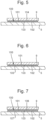
- a single plain bearing 100 is provided between the support plate 4 and the carrier 8.
- the plain bearing 100 has a rectangular area of contact 110 between the bearing surfaces 101 and 102 as shown in Fig. 8 together with the carrier 8.
- the area of contact may be varied and/or plural plain bearings 100 may be provided.
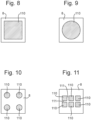
- Figs. 9 to 11 illustrate the areas of contact 110 in some alternative, non-limitative alternative arrangements for the plain bearing 100.
- the area of contact 110 of the plain bearing 100 may have shapes other than rectangular.
- the area of contact 110 may have a circular shape as shown in Fig. 9 , which may be easier to manufacture and/or assist in providing a balanced bearing contact.
- Fig. 10 illustrates an example comprising four plain bearings 100 with circular areas of contact 110 located in the corners of the carrier 8.
- plural plain bearings 100 each formed by one or more bearing members 104 to 107 (as in any of the examples of Figs. 5 to 7 described above) may be provided with channels between the bearing members 104 to 107. Such channels may collect wear particles.
- Fig. 11 illustrates an example of this type comprising six plain bearings 100 with rectangular areas of contact 110 in a regular rectangular array with channels 111 provided therebetween.
- the total area of contact of the bearing surfaces 101 and 102 of the plain bearing 100 (being the total area of all the plain bearings 100 if more than one is provided) is chosen to control the friction and the thermal conductivity. In general, there is a balance between reducing friction by minimising the total area and increasing thermal conductivity by maximising the total area.
- one or more plain bearings 100 can in fact provide good performance as a bearing with friction that is sufficiently low to allow movement perpendicular to the optical axis O, having regard to the force applied by the SMA actuator wires 40.
- the plain bearing 100 maintain a relatively high total area of contact over the bearing surfaces 101 and 102, the impact of wear occurring over time is reduced, compared to a bearing having a point or line contact .
- the total area of contact of the bearing surfaces 101 and 102 of the plain bearing 100 is chosen to be sufficiently large with respect to the size of the image sensor 6 so that the thermal conductivity removes the heat generated thereby.
- the total area of contact may be at least 0.2 times, preferably at least 0.5 times, the area of the light-sensitive region 7 of the image sensor 6.
- the total area of contact may even be larger than the light-sensitive region 7 of the image sensor 6 or larger than the overall dimensions of the image sensor 6.
- the carrier 8 may be arranged to have larger overall dimensions than the image sensor 6.
- the material properties of the bearing surfaces 101 and 102 are chosen to provide a low friction and low wear plain bearing.
- the bearing surfaces 101 and 102 may be designed to have a coefficient of friction of 0.2 or less.
- the bearing surfaces 101 and 102 may each be made from the same material as the element on which it is formed, for example the support plate 5, moving plate 9 or bearing member 104 to 107. That material may be selected to provide suitable properties.
- the bearing member 104 to 107 may be made from a polymer, for example nylon, polytetrafluoroethylene (PTFE) (e.g. Teflon), an acetal (e.g. Delrin) or an Ultra High Molecular Weight Polyethylene (UHMWPE).
- PTFE polytetrafluoroethylene
- acetal e.g. Delrin
- UHMWPE Ultra High Molecular Weight Polyethylene
- the bearing surfaces 101 and 102 may be coated with material selected to provide suitable properties.
- the coating may have lower friction and/or lower wear than the material of the element which is coated, for example the support plate 5, moving plate 9 or bearing member 104 to 107.
- the coating may be made from a polymer, for example nylon, polytetrafluoroethylene (PTFE) (e.g. Teflon), an acetal (e.g. Delrin) or an Ultra High Molecular Weight Polyethylene (UHMWPE).
- PTFE polytetrafluoroethylene
- UHMWPE Ultra High Molecular Weight Polyethylene
- a fluid 103 may be disposed between the bearing surfaces 101 and 102, as shown in the illustrated examples.
- the material properties of the fluid 103 if provided are selected to provide lubrication between the bearing surfaces 101 and 102 so that the coefficient of friction between the bearing surfaces 101 and 102 is reduced and/or to have a thermal conductivity that improve the thermal contact between the bearing surfaces 102 and 103.
- the fluid 103 may be a grease.
- the fluid 103 is optional.
- the bearing surfaces 101 and 102 may be in direct contact. Depending on the material properties of the bearing surfaces 101 and 102 and/or coatings thereon, this may provide a coefficient of friction and a thermal contact that is sufficient.
- the camera assembly 2 comprises two flexures 67 connected between the support structure 4 and the carrier 8 to act as a biasing arrangement that biases the bearing surfaces 101 and 102 together, as well as providing an electrical connection to the image sensor 6.
- the flexures 67 are formed integrally with the moving plate 9 at one end 68 thereof and are mounted to the support plate 5 of the support structure 4 at the other end 69 thereof.
- the flexures 67 could be formed integrally with a plate of the support structure 4 and mounted to the carrier, or else could be separate elements mounted to each of the support structure 4 and the carrier 8.
- the mounting of the flexures 67 may be achieved by soldering which provides both mechanical and electrical connection.
- the flexures 67 are arranged as follows to provide their mechanical function. Each flexure 67 is an elongate beam connected between the support structure 4 and carrier 8. The flexures 67, due to their intrinsic resilience, bias the support structure 4 and the carrier 8 together, the biasing force being applied parallel to the optical axis O. This maintains the contact between the bearing surfaces 101 and 102 of the plain bearing 100. At the same time, the flexures 67 may be laterally deflected to permit lateral movement and rotation of the image sensor 6 relative to the support structure 4 to permit the OIS function.
- the flexures 67 again due to their intrinsic resilience, also provide a lateral biasing force that biases the image sensor 6 towards a central position aligned with the optical axis O of the lens assembly 20 from any direction around that central position.
- the image sensor 6 will tend towards the central position. This ensures that the camera apparatus 1 remains functional to capture images, even in the absence of driving of the SMA actuator wires 40.
- the flexures 67 are designed as follows to provide a suitable retaining force along the optical axis O for the plain bearing 100, and also to permit lateral movement with a lateral biasing force.
- the magnitude of the lateral biasing force is kept low enough as not to hinder OIS, whilst being high enough to centre the image sensor 6 in the absence of driving.
- Each flexure 67 has a cross-section with an average width orthogonal to the optical axis O is that is greater than its average thickness parallel to the optical axis O.
- Each flexure 67 extends in an L-shape around the optical axis O, it in general being desirable that the angular extent is at least 90° as measured between the ends of the flexure 67.
- the flexures 67 are deflected from their relaxed state to provide a pre-loading force that biases the support structure 4 and the carrier 8 together.
- the flexures 67 are made of a suitable material that provides the desired mechanical properties and is electrically conductive.
- the material is a metal having a relatively high yield, for example steel such as stainless steel.
- the flexures 67 support electrical tracks connected to at least the image sensor 6. In this manner, the flexures 67 provide an electrical function, as well as a mechanical function. This avoids the need for a separate electrical connection to be made to the image sensor 6, which could otherwise hinder the movement of the image sensor 6 during OIS.
- any other type of suspension system may be provided.
- a suspension system employing plural beams extending parallel to the optical axis O for example as disclosed in WO-2013/175197 for suspending a lens assembly
- a suspension system employing ball bearings for example as disclosed in WO-2014/083318 for suspending a lens assembly.
- Movement of the image sensor 6 relative to the support structure 4 is driven by an actuator arrangement that is arranged as follows, and seen most easily in Fig. 4 .
- the actuator arrangement is formed by a total of four SMA actuator wires 40 connected between the support structure 4 and the carrier 8.
- the carrier 8 comprises crimp portions 41 fixed to the moving plate 9 and the support structure 4 comprises crimp portions 42 fixed to the rim portion 10.
- the crimp portions 41 and 42 crimp the four SMA actuator wires 40 so as to connect them to the support structure 4 and the carrier 8.
- the crimp portions 41 fixed to the moving plate 9 are formed integrally from a sheet of metal so as to electrically connect the SMA actuator wires 40 together at the carrier 8.
- the crimp portions 41 and 42 are separate elements fixed to the moving plate 9 and the rim portion 10, as an alternative the crimp portions 41 could be formed integrally with the moving plate 9 and/or the crimp portions 42 could be formed integrally with the support plate 5.
- the SMA actuator wires 40 are arranged as follows so that they are capable, on selective driving, of moving the image sensor 6 relative to the support structure 4 in any direction laterally to the light-sensitive region 7 of the image sensor 6 and also of rotating the image sensor 6 about the optical axis O.
- Each of the SMA actuator wires 40 is held in tension, thereby applying a force between the support structure 4 and the carrier 8.
- the SMA actuator wires 40 may be perpendicular to the optical axis O so that the force applied to the carrier 8 is lateral to the light-sensitive region 7 of the image sensor 6.
- the SMA actuator wires 40 may be inclined at a small angle to the light-sensitive region 7 of the image sensor 6 so that the force applied to the carrier 8 includes a component lateral to the light-sensitive region 7 of the image sensor 6 and a component along the optical axis O that acts as a biasing force that biases the bearing surfaces 101 and 102 of the plain bearing 100 together.
- SMA actuator wires 40 will now be described, being similar to that described in WO-2014/083318 , except that they are connected to the carrier 8 for moving the image sensor 6, not to the lens assembly 20.
- SMA material has the property that on heating it undergoes a solid-state phase change which causes the SMA material to contract. At low temperatures the SMA material enters the Martensite phase. At high temperatures the SMA enters the Austenite phase which induces a deformation causing the SMA material to contract. The phase change occurs over a range of temperature due to the statistical spread of transition temperature in the SMA crystal structure. Thus heating of the SMA actuator wires 40 causes them to decrease in length.
- the SMA actuator wires 40 may be made of any suitable SMA material, for example Nitinol or another Titanium-alloy SMA material.
- the material composition and pre-treatment of the SMA actuator wires 40 is chosen to provide phase change over a range of temperature that is above the expected ambient temperature during normal operation and as wide as possible to maximise the degree of positional control.
- the carrier 8 and the image sensor 6 are positioned axially within the aperture 11 of the rim portion 10 of the support structure 4.
- the four SMA actuator wires 40 are arranged on four sides of the image sensor 6.
- the SMA actuator wires 40 are of the same length and have a rotationally symmetrical arrangement.
- a first pair of the SMA actuator wires 40 extend parallel to a first axis (vertical in Fig. 4 ) that is lateral to the light-sensitive region 7 of the image sensor 6.
- the first pair of the SMA actuator wires 40 are oppositely connected to the support structure 4 and the carrier 8 so that they apply forces in opposite directions along the first axis (vertically up and down in Fig. 4 ) .
- the forces applied by the SMA actuator wires 40 of the first pair balance in the event that the tension in each SMA actuator wire 40 is equal. This means that the first pair of the SMA actuator wires 40 apply a first torque to the image sensor 6 (anti-clockwise in Fig. 4 ).
- a second pair of SMA actuator wires 40 extend parallel to a second axis (horizontal in Fig. 4 ) that is lateral to the light-sensitive region 7 of the image sensor 6.
- the second pair of SMA actuator wires 40 are oppositely connected to the support structure 4 and the carrier 8 so that they apply forces in opposite directions along the second axis (horizontally left and right in Fig. 4 ).
- the forces applied by the SMA actuator wires 40 of the second pair balance in the event that the tension in each SMA actuator wire 40 is equal.
- the second pair of the SMA actuator wires 40 apply a second torque (clockwise in Fig. 3 ) to the image sensor 6 that is arranged to be in an opposite sense to the first torque.
- the first and second torques balance in the event that tension in each SMA actuator wire 40 is the same.
- the SMA actuator wires 40 may be selectively driven to move the image sensor 6 in any direction laterally and to rotate the image sensor 6 about the optical axis O. That is:
- the magnitude of the range of movement and rotation depends on the geometry and the range of contraction of the SMA actuator wires 40 within their normal operating parameters.
- This particular arrangement of the SMA actuator wires 40 is advantageous because it can drive the desired lateral movement and rotation with a minimum number of SMA actuator wires.
- other arrangements of SMA actuator wires 40 could be applied. To provide three degrees of motion (two degrees of lateral motion and one degree of rotational motion), then a minimum of four SMA actuator wires 40 are provided. Other arrangements could apply a different number of SMA actuator wires 40. Less SMA actuator wires 40 could be provided for lateral motion, but not rotation. Arrangements with more than four SMA actuator wires 40 are also possible, and may have advantages in allowing additional parameters to be controlled in addition to motion, for example the degree of stress in the SMA actuator wires 40.
- the lateral position and orientation of the image sensor 6 relative to the support structure 4 is controlled by selectively varying the temperature of the SMA actuator wires 40.
- This driving of the SMA actuator wires 40 is achieved by passing selective drive signals through the SMA actuator wires 40 to provide resistive heating. Heating is provided directly by the current of the drive signals. Cooling is provided by reducing or ceasing the current of the drive signals to allow the SMA wire 40 to cool by conduction, convection and radiation to its surroundings.
- the camera apparatus 1 comprises a lens assembly 20 that is assembled with the camera assembly 2 by being mounted to the support structure 4, in particular to the rim portion 10.
- the lens assembly 20 comprises a lens carriage 21 in the form of a cylindrical body that is mounted to the rim portion 10 of the support structure 4.
- the lens carriage supports at least one lens 22 arranged along the optical axis O.
- any number of one or more lenses 22 may be provided.
- the camera apparatus 1 is a miniature camera in which the at least one lens 22 (i.e. each lens 22 if plural lenses are provided) typically have a diameter of at most 10mm.
- the at least one lens 22 of the lens assembly 20 is arranged to focus an image onto the image sensor 6.
- An axial actuator arrangement 24 provided between the lens carriage 21 and the lens holder 23 is arranged to drive movement of the lens holder 21 and lenses 22 along the optical axis O relative to the lens carriage 21.
- the axial actuator arrangement 24 may be any suitable type, for example being a voice coil motor (VCM) or an arrangement of SMA actuator wires, such as is described in WO-2007/113478 .
- VCM voice coil motor
- SMA actuator wires such as is described in WO-2007/113478 .
- the SMA actuator wires 40 are selectively driven to move the image sensor 6 in any direction laterally and to rotate the image sensor 6 about the optical axis O. This is used to provide OIS, compensating for image movement of the camera apparatus 1, caused by for example hand shake.
- Relative movement of the image sensor 6 relative to the support structure 4 and hence also relative to the lens assembly 20 may be used to stabilise the image against tilting of the camera apparatus 1, i.e. rotation about axes extending laterally to the light-sensitive region 7 of the image sensor 6.
- rotation of the images sensor 6 may be used to stabilise the image against rotation of the camera apparatus 1 around the optical axis O. This type of stabilisation is not achieved by a camera apparatus providing OIS-lens shift of the type disclosed in WO-2013/175197 and WO-2014/083318 .
- the SMA actuator wires 40 are driven by the control circuit implemented in the IC chip 30.
- the control circuit generates drive signals for each of the SMA actuator wires 40 and supplies the drive signals to the SMA actuator wires 40.
- the control circuit 30 receives the output signals of the gyroscope sensor 31 which acts as a vibration sensor.
- the gyroscope sensor 31 detects the vibrations that the camera apparatus 1 is experiencing and its output signals represent those vibrations, specifically as the angular velocity of the camera lens element 20 in three dimensions.
- the gyroscope sensor 31 is typically a pair of miniature gyroscopes, for detecting vibration around three axes, being two axes laterally of the light-sensitive region 7 of the image sensor 6 and also the optical axis O. More generally, larger numbers of gyroscopes or other types of vibration sensor could be used.
- the drive signals are generated by the control circuit in response to the output signals of the gyroscope sensor 31 so as to drive movement of the camera lens element 20 to stabilise an image focused by the camera lens element 20 on the image sensor 6, thereby providing OIS.
- the drive signals may be generated using a resistance feedback control technique for example as disclosed in any of International Patent Application No. PCT/GB2013/051325 ; International Patent Application No. PCT/GB2013/052959 ; WO-2012/066285 ; WO-2012/020212 ; WO-2011/104518 ; WO-2012/038703 ; WO-2010/089529 or WO-2010029316 .
Landscapes
- Engineering & Computer Science (AREA)
- Physics & Mathematics (AREA)
- Multimedia (AREA)
- Signal Processing (AREA)
- General Physics & Mathematics (AREA)
- Optics & Photonics (AREA)
- Chemical & Material Sciences (AREA)
- Combustion & Propulsion (AREA)
- Mechanical Engineering (AREA)
- General Engineering & Computer Science (AREA)
- Studio Devices (AREA)
- Adjustment Of Camera Lenses (AREA)
- Transforming Light Signals Into Electric Signals (AREA)
Claims (8)
- Kameraanordnung (2), die umfasst:eine Tragstruktur (4);einen Bildsensor (6), der auf einem Träger (8) montiert ist und einen lichtempfindlichen Bereich (7) aufweist, mindestens ein Gleitlager (100), das eine Lagerfläche (101, 102) auf dem Träger und der Tragstruktur umfasst, wobei die Lagerflächen aneinander anliegen, um den Träger (8) an der Tragstruktur (4) aufzuhängen und eine Bewegung des Bildsensors (6) relativ zur Tragstruktur (4) in jeder Richtung seitlich zum lichtempfindlichen Bereich (7) des Bildsensors (6) zu ermöglichen, und auf eine Weise, die eine Drehung des Bildsensors (6) um eine Achse orthogonal zum lichtempfindlichen Bereich (7) ermöglicht;eine Vielzahl von Formgedächtnislegierungs-Aktuatordrähten (40) in einer Anordnung, die bei selektiver Ansteuerung in der Lage ist, den Bildsensor (6) relativ zur Tragstruktur (4) in jede Richtung seitlich zum lichtempfindlichen Bereich (7) des Bildsensors (6) zu bewegen und den Bildsensor (6) um die Achse zu drehen; undeine Vorspannungsanordnung, die die Lagerflächen (101, 102) gegeneinander vorspannt, wobei die Vorspannungsanordnung mindestens eine Biegevorrichtung (67) umfasst, wobei die Biegevorrichtung (67) elektrische Leiterbahnen trägt, die mit dem Bildsensor verbunden sind.
- Kameraanordnung nach Anspruch 1, wobei die Vielzahl von Formgedächtnislegierungs-Aktuatordrähten (40) insgesamt vier Formgedächtnislegierungs-Aktuatordrähte umfasst.
- Kameraanordnung nach Anspruch 2, wobei die vier Formgedächtnislegierungs-Aktuatordrähte an vier Seiten des Bildsensors (6) angeordnet sind.
- Kameraanordnung nach Anspruch 2 oder 3, wobei die vier Formgedächtnislegierungs-Aktuatordrähte Folgendes umfassen: ein erstes Paar Formgedächtnislegierungs-Aktuatordrähte, die dafür ausgelegt sind, Kräfte auf den Bildsensor (6) in entgegengesetzten Richtungen entlang einer ersten Achse seitlich zu dem lichtempfindlichen Bereich (7) des Bildsensors (6) aufzubringen und ein erstes Drehmoment auf den Bildsensor (6) aufzubringen, und ein zweites Paar Formgedächtnislegierungs-Aktuatordrähte, die dafür ausgelegt sind, Kräfte auf den Bildsensor (6) in entgegengesetzten Richtungen entlang einer zweiten Achse seitlich zu dem lichtempfindlichen Bereich (7) des Bildsensors (6) und senkrecht zu der ersten Achse aufzubringen, und ein zweites Drehmoment auf den Bildsensor (6) in einer entgegengesetzten Richtung zu dem ersten Drehmoment aufzubringen.
- Kameraanordnung nach einem der Ansprüche 1 bis 4, die ferner eine Linsenanordnung (20) umfasst, die mindestens eine Linse (22) umfasst, die dafür ausgelegt ist, ein Bild auf den lichtempfindlichen Bereich (7) des Bildsensors (6) zu fokussieren, wobei die Linsenanordnung (20) an der Tragstruktur (4) angebracht ist.
- Kameraanordnung nach Anspruch 5, wobei der lichtempfindliche Bereich (7) des Bildsensors (6) eine diagonale Länge von höchstens 12 mm aufweist.
- Kameraanordnung nach einem der Ansprüche 1 bis 6, die ferner eine Steuerschaltung (30) umfasst, die zum Antreiben der Formgedächtnis-Aktuatordrähte (40) ausgelegt ist.
- Kameraanordnung nach Anspruch 7, die ferner einen Vibrationssensor (31) umfasst, der dafür ausgelegt ist, Ausgangssignale zu erzeugen, die für die Vibration der Kameraanordnung (2) repräsentativ sind, wobei die Steuerschaltung (30) dafür ausgelegt ist, die Formgedächtnislegierungsdrähte (40) als Reaktion auf die Ausgangssignale des Vibrationssensors (31) anzutreiben, um eine Bewegung des Bildsensors (6) anzutreiben und ein dadurch erfasstes Bild zu stabilisieren.
Applications Claiming Priority (3)
| Application Number | Priority Date | Filing Date | Title |
|---|---|---|---|
| GBGB1519036.6A GB201519036D0 (en) | 2015-10-28 | 2015-10-28 | Thermal management of OIS |
| GBGB1519034.1A GB201519034D0 (en) | 2015-10-28 | 2015-10-28 | Three axis image stabilization |
| PCT/GB2016/053356 WO2017072525A1 (en) | 2015-10-28 | 2016-10-28 | Camera assembly providing optical image stabilisation |
Publications (2)
| Publication Number | Publication Date |
|---|---|
| EP3369245A1 EP3369245A1 (de) | 2018-09-05 |
| EP3369245B1 true EP3369245B1 (de) | 2025-02-26 |
Family
ID=57321353
Family Applications (1)
| Application Number | Title | Priority Date | Filing Date |
|---|---|---|---|
| EP16795404.9A Active EP3369245B1 (de) | 2015-10-28 | 2016-10-28 | Kameraanordnung mit optischer bildstabilisierung |
Country Status (4)
| Country | Link |
|---|---|
| US (2) | US11187916B2 (de) |
| EP (1) | EP3369245B1 (de) |
| CN (3) | CN116055845A (de) |
| WO (1) | WO2017072525A1 (de) |
Families Citing this family (81)
| Publication number | Priority date | Publication date | Assignee | Title |
|---|---|---|---|---|
| US9366879B1 (en) * | 2014-12-02 | 2016-06-14 | Hutchinson Technology Incorporated | Camera lens suspension with polymer bearings |
| US9454016B1 (en) | 2015-03-06 | 2016-09-27 | Hutchinson Technology Incorporated | Camera lens suspension with integrated electrical leads |
| GB201517202D0 (en) * | 2015-09-29 | 2015-11-11 | Cambridge Mechatronics Ltd | OIS actuator improvements |
| EP3369245B1 (de) * | 2015-10-28 | 2025-02-26 | Cambridge Mechatronics Limited | Kameraanordnung mit optischer bildstabilisierung |
| CN107277304B (zh) * | 2016-04-01 | 2020-11-20 | 台湾东电化股份有限公司 | 摄像模块及其控制方法 |
| CN109562592B (zh) | 2016-06-09 | 2022-12-16 | 哈钦森技术股份有限公司 | 用于悬置组件的具有粘合剂的形状记忆合金丝线附接结构 |
| GB201616939D0 (en) * | 2016-10-05 | 2016-11-16 | Cambridge Mechatronics Limited | Protection of bearing in an SMA actuator |
| CN109709741B (zh) * | 2017-10-26 | 2024-06-14 | 华为技术有限公司 | 光学防抖装置 |
| GB201717855D0 (en) * | 2017-10-30 | 2017-12-13 | Cambridge Mechatronics Ltd | SMA actuator bearings |
| CN108600608B (zh) * | 2018-03-16 | 2019-12-31 | 维沃移动通信有限公司 | 一种镜头座、镜头模组及电子设备 |
| CN108881680B (zh) * | 2018-06-12 | 2021-05-07 | 维沃移动通信有限公司 | 一种摄像头结构及移动终端 |
| CN110661963A (zh) * | 2018-06-28 | 2020-01-07 | 格科微电子(上海)有限公司 | 摄像头模组光学防抖的实现方法 |
| KR102584980B1 (ko) | 2018-07-09 | 2023-10-05 | 삼성전기주식회사 | 카메라 모듈 |
| JP7157314B2 (ja) * | 2018-08-22 | 2022-10-20 | ミツミ電機株式会社 | カメラモジュール、及びカメラ搭載装置 |
| CN111835967B (zh) * | 2019-04-19 | 2023-08-18 | 台湾东电化股份有限公司 | 感光组件驱动机构 |
| GB201907188D0 (en) * | 2019-05-21 | 2019-07-03 | Cambridge Mechatronics Ltd | Apparatus |
| JP7045784B2 (ja) * | 2019-06-01 | 2022-04-01 | エーエーシー オプティックス ソリューションズ ピーティーイー リミテッド | レンズユニット |
| JP7097664B2 (ja) * | 2019-06-01 | 2022-07-08 | エーエーシー オプティックス ソリューションズ ピーティーイー リミテッド | オートフォーカスレンズユニット |
| WO2020243858A1 (zh) * | 2019-06-01 | 2020-12-10 | 瑞声光学解决方案私人有限公司 | 自动对焦镜头组件 |
| US11503211B2 (en) * | 2019-08-16 | 2022-11-15 | Hutchinson Technology Incorporated | Stabilization suspensions and methods of manufacture |
| CN110809132B (zh) * | 2019-10-22 | 2021-03-30 | 北京海益同展信息科技有限公司 | 一种图像采集装置 |
| CN112887521B (zh) * | 2019-11-30 | 2022-07-26 | 华为技术有限公司 | 摄像头模组及电子设备 |
| CN112887520B (zh) * | 2019-11-30 | 2022-08-26 | 华为技术有限公司 | 摄像头模组及电子设备 |
| JP7426816B2 (ja) * | 2019-12-20 | 2024-02-02 | ローム株式会社 | カメラモジュール |
| US11947180B2 (en) * | 2019-12-26 | 2024-04-02 | Tdk Taiwan Corp. | Optical system |
| CN113259547B (zh) * | 2020-02-11 | 2022-11-11 | 华为技术有限公司 | Sma马达、摄像头模组及电子设备 |
| GB2593681A (en) * | 2020-03-26 | 2021-10-06 | Cambridge Mechatronics Ltd | A shape memory actuator |
| CN111443498A (zh) * | 2020-04-15 | 2020-07-24 | Oppo广东移动通信有限公司 | 镜头模组以及电子设备 |
| CN113542539B (zh) * | 2020-04-16 | 2022-10-04 | 宁波舜宇光电信息有限公司 | 具有防抖功能的感光组件及相应摄像模组 |
| WO2021229228A1 (en) * | 2020-05-13 | 2021-11-18 | Cambridge Mechatronics Limited | A shape memory alloy actuator assembly and a method of manufacturing thereof |
| CN111929971B (zh) * | 2020-08-06 | 2025-04-18 | 河南皓泽电子股份有限公司昆山分公司 | 实现大转角的微云台 |
| GB202110839D0 (en) * | 2021-07-28 | 2021-09-08 | Cambridge Mechatronics Ltd | Actuator assembly |
| US12316936B2 (en) * | 2020-08-31 | 2025-05-27 | Cambridge Mechatronics Limited | Actuator assembly |
| CN114257710B (zh) * | 2020-09-23 | 2024-02-20 | 北京小米移动软件有限公司 | 光学防抖结构及具有其的摄像头模组、终端设备 |
| GB202015414D0 (en) | 2020-09-29 | 2020-11-11 | Cambridge Mechatronics Ltd | Actuator assembly |
| CN114430455B (zh) | 2020-10-29 | 2025-10-31 | 华为技术有限公司 | 图像传感器防抖组件、摄像装置及电子设备 |
| CN114513588B (zh) * | 2020-11-17 | 2023-09-12 | 华为技术有限公司 | Sma马达、摄像模组及电子设备 |
| GB2601002A (en) | 2020-11-17 | 2022-05-18 | Cambridge Mechatronics Ltd | A computer-implemented method for optical image stabilisation |
| CN114531538A (zh) * | 2020-11-23 | 2022-05-24 | 格科微电子(上海)有限公司 | 光学防抖装置、电子设备 |
| CN114531540B (zh) * | 2020-11-23 | 2025-07-18 | 格科微电子(上海)有限公司 | 光学防抖装置、电子设备 |
| CN114584637B (zh) * | 2020-11-28 | 2023-07-18 | 华为技术有限公司 | 形状记忆合金马达、马达模组、摄像头模组、电子设备 |
| CN112770045B (zh) * | 2020-12-11 | 2022-08-23 | 南昌欧菲光电技术有限公司 | 摄像模组和电子设备 |
| WO2022129894A1 (en) | 2020-12-14 | 2022-06-23 | Cambridge Mechatronics Limited | Computer-implemented method of generating pwm control signals, and corresponding computer program, computer-readable storage medium and apparatus |
| GB2601833A (en) | 2020-12-14 | 2022-06-15 | Cambridge Mechatronics Ltd | Computer-implemented method of generating PWM control signals, and corresponding computer program, computer-readable storage medium and apparatus |
| GB2601834A (en) | 2020-12-14 | 2022-06-15 | Cambridge Mechatronics Ltd | Computer-implemented method of generating PWM control signals, and corresponding computer program, computer-readable storage medium and apparatus |
| GB202104687D0 (en) | 2021-03-31 | 2021-05-12 | Cambridge Mechatronics Ltd | An actuator assembly and a method of operating thereof |
| GB2607269A (en) | 2021-04-14 | 2022-12-07 | Cambridge Mechatronics Ltd | SMA actuator assembly |
| EP4348325A1 (de) | 2021-06-02 | 2024-04-10 | Cambridge Mechatronics Limited | Aktuatoranordnung |
| GB2607594B (en) | 2021-06-07 | 2024-05-08 | Cambridge Mechatronics Ltd | A method of generating drive signals for driving an SMA apparatus |
| KR102516773B1 (ko) * | 2021-06-14 | 2023-03-31 | 삼성전기주식회사 | 센서 액추에이터 및 이를 포함하는 카메라 모듈 |
| GB2609037B (en) * | 2021-07-20 | 2023-12-27 | Cambridge Mechatronics Ltd | Actuator assembly |
| GB2609046B (en) | 2021-07-20 | 2023-12-27 | Cambridge Mechatronics Ltd | SMA actuator assembly |
| US20250097577A1 (en) * | 2021-08-02 | 2025-03-20 | Cambridge Mechatronics Limited | Actuator assembly |
| GB202116400D0 (en) | 2021-11-15 | 2021-12-29 | Cambridge Mechatronics Ltd | An actuator assembly |
| KR102597174B1 (ko) | 2021-11-23 | 2023-11-02 | 삼성전기주식회사 | 센서 시프트 모듈 및 이를 포함하는 카메라 모듈 |
| KR102597173B1 (ko) * | 2021-11-23 | 2023-11-02 | 삼성전기주식회사 | 센서 시프트 모듈 및 이를 포함하는 카메라 모듈 |
| EP4437231A1 (de) | 2021-11-24 | 2024-10-02 | Cambridge Mechatronics Limited | Aktuatoranordnung |
| GB2629264B (en) | 2021-12-22 | 2025-09-24 | Cambridge Mechatronics Ltd | Actuator assembly |
| WO2023126632A1 (en) | 2021-12-31 | 2023-07-06 | Cambridge Mechatronics Limited | Actuator assembly |
| GB202119163D0 (en) | 2021-12-31 | 2022-02-16 | Cambridge Mechatronics Ltd | Actuator assembly |
| KR102642907B1 (ko) | 2022-01-07 | 2024-03-04 | 삼성전기주식회사 | 센서 액추에이터 및 이를 포함하는 카메라 모듈 |
| WO2023135431A1 (en) | 2022-01-13 | 2023-07-20 | Cambridge Mechatronics Limited | Actuator assembly |
| JP2023103766A (ja) * | 2022-01-14 | 2023-07-27 | キヤノン株式会社 | 撮像装置 |
| GB202204749D0 (en) | 2022-03-31 | 2022-05-18 | Cambridge Mechatronics Ltd | Actuator assembly |
| GB2617179A (en) | 2022-03-31 | 2023-10-04 | Cambridge Mechatronics Ltd | Actuator Assembly |
| GB2617332A (en) | 2022-04-02 | 2023-10-11 | Cambridge Mechatronics Ltd | Actuator assembly |
| CN116980752A (zh) * | 2022-04-15 | 2023-10-31 | 华为技术有限公司 | 摄像头模组和电子设备 |
| CN119096047A (zh) | 2022-04-28 | 2024-12-06 | 剑桥机电有限公司 | 致动器组件 |
| GB2619952B (en) | 2022-06-22 | 2024-11-27 | Cambridge Mechatronics Ltd | A method of controlling power delivered to an actuator assembly |
| GB2621604A (en) * | 2022-08-17 | 2024-02-21 | Cambridge Mechatronics Ltd | Actuator assembly and method of assembling an actuator assembly |
| CN119768606A (zh) * | 2022-08-30 | 2025-04-04 | 剑桥机电有限公司 | 致动器组件 |
| WO2024057042A1 (en) | 2022-09-16 | 2024-03-21 | Cambridge Mechatronics Limited | Variable aperture assembly |
| GB2628607A (en) | 2023-03-30 | 2024-10-02 | Cambridge Mechatronics Ltd | Actuator assembly |
| GB2630392A (en) | 2023-05-26 | 2024-11-27 | Cambridge Mechatronics Ltd | Actuator assembly |
| WO2024246562A1 (en) | 2023-06-01 | 2024-12-05 | Cambridge Mechatronics Limited | Actuator assembly |
| WO2025012590A1 (en) | 2023-07-07 | 2025-01-16 | Cambridge Mechatronics Limited | Actuator assembly |
| GB2632813A (en) | 2023-08-21 | 2025-02-26 | Cambridge Mechatronics Ltd | Actuator assembly |
| GB2633335A (en) | 2023-09-06 | 2025-03-12 | Cambridge Mechatronics Ltd | Actuator assembly |
| GB2633351A (en) | 2023-09-07 | 2025-03-12 | Cambridge Mechatronics Ltd | Actuator assembly |
| WO2025074084A1 (en) | 2023-10-06 | 2025-04-10 | Cambridge Mechatronics Limited | Actuator assembly |
| GB2641754A (en) | 2024-06-11 | 2025-12-17 | Cambridge Mechatronics Ltd | Actuator assembly |
Citations (1)
| Publication number | Priority date | Publication date | Assignee | Title |
|---|---|---|---|---|
| US20060061660A1 (en) * | 2004-09-18 | 2006-03-23 | Deutsche Telekom Ag | Image stabilization device |
Family Cites Families (35)
| Publication number | Priority date | Publication date | Assignee | Title |
|---|---|---|---|---|
| KR100318330B1 (ko) | 1991-04-08 | 2002-04-22 | 가나이 쓰도무 | 감시장치 |
| US5684640A (en) | 1994-04-27 | 1997-11-04 | Nikon Corporation | Camera with vibration compensation device having anti-vibration lens urging mechanism and feed screw mechanism |
| US6064827A (en) | 1997-05-16 | 2000-05-16 | Canon Kabushiki Kaisha | Image stabilizer |
| JP3783410B2 (ja) | 1998-05-28 | 2006-06-07 | コニカミノルタフォトイメージング株式会社 | 補正光学装置 |
| DE102004002890A1 (de) | 2004-01-20 | 2005-08-18 | Vif Videotechnik für Industrie + Forschung GmbH | Kamera |
| JP3952205B2 (ja) | 2004-11-19 | 2007-08-01 | 株式会社タムロン | アクチュエータ及びそれを備えたレンズユニット及びカメラ |
| JP4857550B2 (ja) * | 2004-12-06 | 2012-01-18 | コニカミノルタホールディングス株式会社 | 駆動装置および駆動システム |
| JP2006171528A (ja) * | 2004-12-17 | 2006-06-29 | Konica Minolta Photo Imaging Inc | 駆動機構、駆動装置、振れ補正ユニット及び撮像装置 |
| JP2007025616A (ja) * | 2005-06-15 | 2007-02-01 | Pentax Corp | ステージ装置及びこのステージ装置を利用したカメラの像振れ補正装置 |
| CN100568076C (zh) | 2005-06-15 | 2009-12-09 | Hoya株式会社 | 台架设备和利用该台架设备的照相机图像移动校正设备 |
| JP4640048B2 (ja) | 2005-08-30 | 2011-03-02 | コニカミノルタオプト株式会社 | 駆動装置及びこれを用いた撮像装置 |
| JP2007139965A (ja) * | 2005-11-16 | 2007-06-07 | Konica Minolta Opto Inc | 駆動装置 |
| GB2451972B (en) | 2006-03-30 | 2010-06-30 | 1 Ltd | Camera lens actuation apparatus |
| US20080074744A1 (en) | 2006-09-27 | 2008-03-27 | Nikon Corporation | Vibration reduction apparatus, optical equipment and a method of manufacturing the vibration reduction apparatus |
| GB0702676D0 (en) | 2007-02-12 | 2007-03-21 | 1 Ltd | Method of driving a shape memory alloy actuator |
| JP2008203402A (ja) * | 2007-02-19 | 2008-09-04 | Konica Minolta Opto Inc | センサ装置、および撮像装置 |
| JP2008233526A (ja) | 2007-03-20 | 2008-10-02 | Tamron Co Ltd | 像振れ防止用アクチュエータ及びそれを備えたカメラ |
| WO2010029316A2 (en) | 2008-09-12 | 2010-03-18 | Cambridge Mechatronics Limited | Optical image stabilisation |
| EP2394425B1 (de) | 2009-02-09 | 2017-05-31 | Cambridge Mechatronics Limited | Optische bildstabilisierung |
| JP5090410B2 (ja) | 2009-03-04 | 2012-12-05 | 株式会社リコー | 像振れ補正装置、レンズ鏡筒、撮像装置および携帯情報端末 |
| KR101582088B1 (ko) | 2009-04-20 | 2016-01-04 | 삼성전자주식회사 | 디지털 카메라의 흔들림 보상용 구동조립체 |
| JP4804564B2 (ja) | 2009-07-14 | 2011-11-02 | キヤノン株式会社 | 振れ補正装置を有する光学機器 |
| US8830335B2 (en) * | 2010-02-26 | 2014-09-09 | Cambridge Mechatronics Limited | SMA actuation apparatus |
| JP5570301B2 (ja) | 2010-05-27 | 2014-08-13 | キヤノン株式会社 | 像振れ補正装置および光学機器 |
| US9137429B2 (en) * | 2010-08-09 | 2015-09-15 | Cambridge Mechatronics Limited | Camera apparatus |
| US8866918B2 (en) | 2010-09-22 | 2014-10-21 | Cambridge Mechatronics Limited | Optical image stabilisation |
| GB201019532D0 (en) | 2010-11-18 | 2010-12-29 | Cambridge Mechatronics Ltd | Optical image stablisation drive |
| TWI416240B (zh) | 2011-03-30 | 2013-11-21 | Largan Precision Co Ltd | 攝影模組 |
| JP5720556B2 (ja) * | 2011-12-14 | 2015-05-20 | 株式会社Jvcケンウッド | 撮像装置及び画像ぶれ補正方法 |
| EP2813877A4 (de) | 2012-02-07 | 2015-09-02 | Konica Minolta Inc | Antriebsvorrichtung und linseneinheit |
| KR101932795B1 (ko) * | 2012-05-25 | 2018-12-26 | 캠브리지 메카트로닉스 리미티드 | 형상 기억 합금 작동 장치 |
| GB201220485D0 (en) | 2012-11-14 | 2012-12-26 | Cambridge Mechatronics Ltd | Control of an SMA actuation apparatus |
| GB201221306D0 (en) | 2012-11-27 | 2013-01-09 | Cambridge Mechatronics Ltd | Suspension system for a camera lens element |
| US9366879B1 (en) | 2014-12-02 | 2016-06-14 | Hutchinson Technology Incorporated | Camera lens suspension with polymer bearings |
| EP3369245B1 (de) * | 2015-10-28 | 2025-02-26 | Cambridge Mechatronics Limited | Kameraanordnung mit optischer bildstabilisierung |
-
2016
- 2016-10-28 EP EP16795404.9A patent/EP3369245B1/de active Active
- 2016-10-28 CN CN202310052544.1A patent/CN116055845A/zh active Pending
- 2016-10-28 CN CN202310052578.0A patent/CN116017121B/zh active Active
- 2016-10-28 CN CN201680060899.3A patent/CN108141541A/zh active Pending
- 2016-10-28 US US15/770,386 patent/US11187916B2/en active Active
- 2016-10-28 WO PCT/GB2016/053356 patent/WO2017072525A1/en not_active Ceased
-
2021
- 2021-10-19 US US17/504,790 patent/US12313858B2/en active Active
Patent Citations (1)
| Publication number | Priority date | Publication date | Assignee | Title |
|---|---|---|---|---|
| US20060061660A1 (en) * | 2004-09-18 | 2006-03-23 | Deutsche Telekom Ag | Image stabilization device |
Also Published As
| Publication number | Publication date |
|---|---|
| US20220035176A1 (en) | 2022-02-03 |
| US12313858B2 (en) | 2025-05-27 |
| US11187916B2 (en) | 2021-11-30 |
| CN116017121B (zh) | 2025-08-22 |
| WO2017072525A1 (en) | 2017-05-04 |
| CN108141541A (zh) | 2018-06-08 |
| EP3369245A1 (de) | 2018-09-05 |
| US20180321503A1 (en) | 2018-11-08 |
| CN116055845A (zh) | 2023-05-02 |
| CN116017121A (zh) | 2023-04-25 |
Similar Documents
| Publication | Publication Date | Title |
|---|---|---|
| US12313858B2 (en) | Camera assembly providing optical image stabilisation | |
| US11048098B2 (en) | Shape memory alloy actuator arrangement | |
| US9609219B2 (en) | Suspension system for a camera lens element | |
| CN113168023B (zh) | 用于光学图像稳定的sma致动器 | |
| US9753300B2 (en) | Shape memory alloy actuation apparatus | |
| EP3411741B1 (de) | Kameralinsenbetätigungsanordnung | |
| US20170219842A1 (en) | Camera assembly | |
| JP2013520701A (ja) | Sma作動装置 | |
| GB2601112A (en) | Camera apparatus | |
| US20230328348A1 (en) | Actuator assembly | |
| CN115427680A (zh) | 致动器组件 | |
| US20250097577A1 (en) | Actuator assembly | |
| WO2022069888A1 (en) | Actuator assembly | |
| CN118489083A (zh) | 致动器组件 | |
| CN117597938A (zh) | 致动器组件 |
Legal Events
| Date | Code | Title | Description |
|---|---|---|---|
| STAA | Information on the status of an ep patent application or granted ep patent |
Free format text: STATUS: UNKNOWN |
|
| STAA | Information on the status of an ep patent application or granted ep patent |
Free format text: STATUS: THE INTERNATIONAL PUBLICATION HAS BEEN MADE |
|
| PUAI | Public reference made under article 153(3) epc to a published international application that has entered the european phase |
Free format text: ORIGINAL CODE: 0009012 |
|
| STAA | Information on the status of an ep patent application or granted ep patent |
Free format text: STATUS: REQUEST FOR EXAMINATION WAS MADE |
|
| 17P | Request for examination filed |
Effective date: 20180521 |
|
| AK | Designated contracting states |
Kind code of ref document: A1 Designated state(s): AL AT BE BG CH CY CZ DE DK EE ES FI FR GB GR HR HU IE IS IT LI LT LU LV MC MK MT NL NO PL PT RO RS SE SI SK SM TR |
|
| AX | Request for extension of the european patent |
Extension state: BA ME |
|
| DAV | Request for validation of the european patent (deleted) | ||
| DAX | Request for extension of the european patent (deleted) | ||
| STAA | Information on the status of an ep patent application or granted ep patent |
Free format text: STATUS: EXAMINATION IS IN PROGRESS |
|
| 17Q | First examination report despatched |
Effective date: 20190906 |
|
| REG | Reference to a national code |
Ref country code: DE Ref legal event code: R079 Free format text: PREVIOUS MAIN CLASS: H04N0005232000 Ipc: F03G0007060000 Ref document number: 602016091377 Country of ref document: DE |
|
| GRAP | Despatch of communication of intention to grant a patent |
Free format text: ORIGINAL CODE: EPIDOSNIGR1 |
|
| STAA | Information on the status of an ep patent application or granted ep patent |
Free format text: STATUS: GRANT OF PATENT IS INTENDED |
|
| RIC1 | Information provided on ipc code assigned before grant |
Ipc: H04N 23/68 20230101ALI20241125BHEP Ipc: H04N 23/54 20230101ALI20241125BHEP Ipc: G02B 27/64 20060101ALI20241125BHEP Ipc: F03G 7/06 20060101AFI20241125BHEP |
|
| INTG | Intention to grant announced |
Effective date: 20241212 |
|
| GRAS | Grant fee paid |
Free format text: ORIGINAL CODE: EPIDOSNIGR3 |
|
| GRAA | (expected) grant |
Free format text: ORIGINAL CODE: 0009210 |
|
| STAA | Information on the status of an ep patent application or granted ep patent |
Free format text: STATUS: THE PATENT HAS BEEN GRANTED |
|
| RAP3 | Party data changed (applicant data changed or rights of an application transferred) |
Owner name: CAMBRIDGE MECHATRONICS LIMITED |
|
| AK | Designated contracting states |
Kind code of ref document: B1 Designated state(s): AL AT BE BG CH CY CZ DE DK EE ES FI FR GB GR HR HU IE IS IT LI LT LU LV MC MK MT NL NO PL PT RO RS SE SI SK SM TR |
|
| REG | Reference to a national code |
Ref country code: GB Ref legal event code: FG4D |
|
| REG | Reference to a national code |
Ref country code: CH Ref legal event code: EP |
|
| REG | Reference to a national code |
Ref country code: DE Ref legal event code: R096 Ref document number: 602016091377 Country of ref document: DE |
|
| REG | Reference to a national code |
Ref country code: IE Ref legal event code: FG4D |
|
| P01 | Opt-out of the competence of the unified patent court (upc) registered |
Free format text: CASE NUMBER: APP_12504/2025 Effective date: 20250313 |
|
| REG | Reference to a national code |
Ref country code: NL Ref legal event code: MP Effective date: 20250226 |
|
| PG25 | Lapsed in a contracting state [announced via postgrant information from national office to epo] |
Ref country code: RS Free format text: LAPSE BECAUSE OF FAILURE TO SUBMIT A TRANSLATION OF THE DESCRIPTION OR TO PAY THE FEE WITHIN THE PRESCRIBED TIME-LIMIT Effective date: 20250526 |
|
| PG25 | Lapsed in a contracting state [announced via postgrant information from national office to epo] |
Ref country code: FI Free format text: LAPSE BECAUSE OF FAILURE TO SUBMIT A TRANSLATION OF THE DESCRIPTION OR TO PAY THE FEE WITHIN THE PRESCRIBED TIME-LIMIT Effective date: 20250226 |
|
| PG25 | Lapsed in a contracting state [announced via postgrant information from national office to epo] |
Ref country code: PL Free format text: LAPSE BECAUSE OF FAILURE TO SUBMIT A TRANSLATION OF THE DESCRIPTION OR TO PAY THE FEE WITHIN THE PRESCRIBED TIME-LIMIT Effective date: 20250226 |
|
| PG25 | Lapsed in a contracting state [announced via postgrant information from national office to epo] |
Ref country code: ES Free format text: LAPSE BECAUSE OF FAILURE TO SUBMIT A TRANSLATION OF THE DESCRIPTION OR TO PAY THE FEE WITHIN THE PRESCRIBED TIME-LIMIT Effective date: 20250226 |
|
| REG | Reference to a national code |
Ref country code: LT Ref legal event code: MG9D |
|
| PG25 | Lapsed in a contracting state [announced via postgrant information from national office to epo] |
Ref country code: NO Free format text: LAPSE BECAUSE OF FAILURE TO SUBMIT A TRANSLATION OF THE DESCRIPTION OR TO PAY THE FEE WITHIN THE PRESCRIBED TIME-LIMIT Effective date: 20250526 Ref country code: IS Free format text: LAPSE BECAUSE OF FAILURE TO SUBMIT A TRANSLATION OF THE DESCRIPTION OR TO PAY THE FEE WITHIN THE PRESCRIBED TIME-LIMIT Effective date: 20250626 |
|
| PG25 | Lapsed in a contracting state [announced via postgrant information from national office to epo] |
Ref country code: NL Free format text: LAPSE BECAUSE OF FAILURE TO SUBMIT A TRANSLATION OF THE DESCRIPTION OR TO PAY THE FEE WITHIN THE PRESCRIBED TIME-LIMIT Effective date: 20250226 |
|
| PG25 | Lapsed in a contracting state [announced via postgrant information from national office to epo] |
Ref country code: HR Free format text: LAPSE BECAUSE OF FAILURE TO SUBMIT A TRANSLATION OF THE DESCRIPTION OR TO PAY THE FEE WITHIN THE PRESCRIBED TIME-LIMIT Effective date: 20250226 |
|
| PG25 | Lapsed in a contracting state [announced via postgrant information from national office to epo] |
Ref country code: LV Free format text: LAPSE BECAUSE OF FAILURE TO SUBMIT A TRANSLATION OF THE DESCRIPTION OR TO PAY THE FEE WITHIN THE PRESCRIBED TIME-LIMIT Effective date: 20250226 Ref country code: PT Free format text: LAPSE BECAUSE OF FAILURE TO SUBMIT A TRANSLATION OF THE DESCRIPTION OR TO PAY THE FEE WITHIN THE PRESCRIBED TIME-LIMIT Effective date: 20250626 |
|
| PG25 | Lapsed in a contracting state [announced via postgrant information from national office to epo] |
Ref country code: GR Free format text: LAPSE BECAUSE OF FAILURE TO SUBMIT A TRANSLATION OF THE DESCRIPTION OR TO PAY THE FEE WITHIN THE PRESCRIBED TIME-LIMIT Effective date: 20250527 Ref country code: BG Free format text: LAPSE BECAUSE OF FAILURE TO SUBMIT A TRANSLATION OF THE DESCRIPTION OR TO PAY THE FEE WITHIN THE PRESCRIBED TIME-LIMIT Effective date: 20250226 |
|
| REG | Reference to a national code |
Ref country code: AT Ref legal event code: MK05 Ref document number: 1770853 Country of ref document: AT Kind code of ref document: T Effective date: 20250226 |
|
| PG25 | Lapsed in a contracting state [announced via postgrant information from national office to epo] |
Ref country code: SE Free format text: LAPSE BECAUSE OF FAILURE TO SUBMIT A TRANSLATION OF THE DESCRIPTION OR TO PAY THE FEE WITHIN THE PRESCRIBED TIME-LIMIT Effective date: 20250226 |
|
| PG25 | Lapsed in a contracting state [announced via postgrant information from national office to epo] |
Ref country code: SM Free format text: LAPSE BECAUSE OF FAILURE TO SUBMIT A TRANSLATION OF THE DESCRIPTION OR TO PAY THE FEE WITHIN THE PRESCRIBED TIME-LIMIT Effective date: 20250226 |
|
| PG25 | Lapsed in a contracting state [announced via postgrant information from national office to epo] |
Ref country code: DK Free format text: LAPSE BECAUSE OF FAILURE TO SUBMIT A TRANSLATION OF THE DESCRIPTION OR TO PAY THE FEE WITHIN THE PRESCRIBED TIME-LIMIT Effective date: 20250226 |
|
| PG25 | Lapsed in a contracting state [announced via postgrant information from national office to epo] |
Ref country code: IT Free format text: LAPSE BECAUSE OF FAILURE TO SUBMIT A TRANSLATION OF THE DESCRIPTION OR TO PAY THE FEE WITHIN THE PRESCRIBED TIME-LIMIT Effective date: 20250226 |
|
| PG25 | Lapsed in a contracting state [announced via postgrant information from national office to epo] |
Ref country code: AT Free format text: LAPSE BECAUSE OF FAILURE TO SUBMIT A TRANSLATION OF THE DESCRIPTION OR TO PAY THE FEE WITHIN THE PRESCRIBED TIME-LIMIT Effective date: 20250226 |
|
| PG25 | Lapsed in a contracting state [announced via postgrant information from national office to epo] |
Ref country code: CZ Free format text: LAPSE BECAUSE OF FAILURE TO SUBMIT A TRANSLATION OF THE DESCRIPTION OR TO PAY THE FEE WITHIN THE PRESCRIBED TIME-LIMIT Effective date: 20250226 Ref country code: EE Free format text: LAPSE BECAUSE OF FAILURE TO SUBMIT A TRANSLATION OF THE DESCRIPTION OR TO PAY THE FEE WITHIN THE PRESCRIBED TIME-LIMIT Effective date: 20250226 |
|
| PG25 | Lapsed in a contracting state [announced via postgrant information from national office to epo] |
Ref country code: RO Free format text: LAPSE BECAUSE OF FAILURE TO SUBMIT A TRANSLATION OF THE DESCRIPTION OR TO PAY THE FEE WITHIN THE PRESCRIBED TIME-LIMIT Effective date: 20250226 |
|
| PG25 | Lapsed in a contracting state [announced via postgrant information from national office to epo] |
Ref country code: SK Free format text: LAPSE BECAUSE OF FAILURE TO SUBMIT A TRANSLATION OF THE DESCRIPTION OR TO PAY THE FEE WITHIN THE PRESCRIBED TIME-LIMIT Effective date: 20250226 |
|
| REG | Reference to a national code |
Ref country code: DE Ref legal event code: R097 Ref document number: 602016091377 Country of ref document: DE |
|
| PLBE | No opposition filed within time limit |
Free format text: ORIGINAL CODE: 0009261 |
|
| STAA | Information on the status of an ep patent application or granted ep patent |
Free format text: STATUS: NO OPPOSITION FILED WITHIN TIME LIMIT |
|
| PGFP | Annual fee paid to national office [announced via postgrant information from national office to epo] |
Ref country code: DE Payment date: 20251021 Year of fee payment: 10 |
|
| PGFP | Annual fee paid to national office [announced via postgrant information from national office to epo] |
Ref country code: GB Payment date: 20251022 Year of fee payment: 10 |
|
| PGFP | Annual fee paid to national office [announced via postgrant information from national office to epo] |
Ref country code: FR Payment date: 20251030 Year of fee payment: 10 |
|
| 26N | No opposition filed |
Effective date: 20251127 |