EP3367802B1 - System zum formen von hacksteacks - Google Patents
System zum formen von hacksteacks Download PDFInfo
- Publication number
- EP3367802B1 EP3367802B1 EP16809952.1A EP16809952A EP3367802B1 EP 3367802 B1 EP3367802 B1 EP 3367802B1 EP 16809952 A EP16809952 A EP 16809952A EP 3367802 B1 EP3367802 B1 EP 3367802B1
- Authority
- EP
- European Patent Office
- Prior art keywords
- mould
- grinding plate
- section
- tubular section
- mold
- Prior art date
- Legal status (The legal status is an assumption and is not a legal conclusion. Google has not performed a legal analysis and makes no representation as to the accuracy of the status listed.)
- Active
Links
Images


Classifications
-
- A—HUMAN NECESSITIES
- A22—BUTCHERING; MEAT TREATMENT; PROCESSING POULTRY OR FISH
- A22C—PROCESSING MEAT, POULTRY, OR FISH
- A22C7/00—Apparatus for pounding, forming, or pressing meat, sausage-meat, or meat products
- A22C7/0023—Pressing means
- A22C7/003—Meat-moulds
- A22C7/0076—Devices for making meat patties
-
- A—HUMAN NECESSITIES
- A22—BUTCHERING; MEAT TREATMENT; PROCESSING POULTRY OR FISH
- A22C—PROCESSING MEAT, POULTRY, OR FISH
- A22C17/00—Other devices for processing meat or bones
- A22C17/0006—Cutting or shaping meat
- A22C17/0026—Mincing and grinding meat
-
- A—HUMAN NECESSITIES
- A22—BUTCHERING; MEAT TREATMENT; PROCESSING POULTRY OR FISH
- A22C—PROCESSING MEAT, POULTRY, OR FISH
- A22C7/00—Apparatus for pounding, forming, or pressing meat, sausage-meat, or meat products
-
- A—HUMAN NECESSITIES
- A22—BUTCHERING; MEAT TREATMENT; PROCESSING POULTRY OR FISH
- A22C—PROCESSING MEAT, POULTRY, OR FISH
- A22C7/00—Apparatus for pounding, forming, or pressing meat, sausage-meat, or meat products
- A22C7/0023—Pressing means
- A22C7/003—Meat-moulds
-
- A—HUMAN NECESSITIES
- A22—BUTCHERING; MEAT TREATMENT; PROCESSING POULTRY OR FISH
- A22C—PROCESSING MEAT, POULTRY, OR FISH
- A22C7/00—Apparatus for pounding, forming, or pressing meat, sausage-meat, or meat products
- A22C7/0023—Pressing means
- A22C7/003—Meat-moulds
- A22C7/0069—Pressing and moulding by means of a drum
-
- A—HUMAN NECESSITIES
- A22—BUTCHERING; MEAT TREATMENT; PROCESSING POULTRY OR FISH
- A22C—PROCESSING MEAT, POULTRY, OR FISH
- A22C7/00—Apparatus for pounding, forming, or pressing meat, sausage-meat, or meat products
- A22C7/0092—Apparatus for pounding, forming, or pressing meat, sausage-meat, or meat products with worms or other rotary mounted members
Definitions
- the invention relates to a system for forming minced steaks from a mass of meat.
- systems for forming hamburger steaks are used.
- Such systems are for example described in the document WO2004 / 002229 .
- they comprise a base 1 comprising a feed pump, a hopper 11 receiving a mass of meat to be shaped.
- the pump being connected to an outlet of the hopper, it supplies, via a supply line, one or more inlets of a forming mold 12, here in the form of a cylindrical mold.
- the minced steaks thus formed by the mold 12 are then placed on an exit conveyor 13 for subsequent packaging.
- WO2015 / 012690 discloses a system for forming ground steaks, comprising a mass feed member which is provided with an orifice mouth body having multiple outlet ports forming the mouth so that the mass flows into a cavity mold through said multiple outlet ports, and in that the mass feed member is provided with multiple movable grinding members at said distinct perpendicular axis positions when viewed perpendicular to the path of the mold member .
- US4205415 describes a system for forming ground steaks, comprising knives for cutting the meat before continuing the extrusion.
- a conventional planar grinding plate is sealed to the adapter and has a plurality of openings.
- US5030164 discloses a system for forming ground steaks, comprising a base plate having a cylindrical opening into which is received a disc-shaped or cylindrical filling plate which can rotate about its central axis relative to the base plate.
- the base plate further includes a cutting blade or knife whose cutting edges are oriented in opposite directions.
- An object of the invention is to provide a system for forming hamburger steaks which makes it possible to produce all the variants of hamburger steaks without being dedicated to a single variant.
- the presence of retaining means distributed along the tubing section in a discrete manner makes it possible to position the grinding plate at selected distances from the mold, thus making it possible to distribute the minced meat fibers differently in the volume of the cake forming the final ground steak.
- the first aspect of the disclosure also relates to a method of implementing the system having at least one of the preceding technical characteristics.
- the third aspect of the disclosure also relates to a method of making a minced steak comprising one or more through orifices, the method implementing the preceding system.
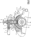
- the system for forming minced steaks 10 according to the invention comprises a base 1 comprising, in a manner known per se, means for controlling and implementing the system for forming minced steaks 10 according to the invention.
- the base 1 comprises a feed pump, an inlet of which is connected to an outlet of a hopper 11 in which meat intended for the production of minced steaks is stored.
- the meat contained in the hopper 11 may or may not be minced.
- An outlet of the feed pump is connected to one or more inlets 121 of a mold 12 by a supply line 3 (visible on the figure 2 for example) meat mass.
- the supply pipe 3 is connected to each of the inlets 121 of the mold 12 via an interfacing element 21 which will be described in more detail in the remainder of this description.
- the mold 12 is a rotary drum type mold known per se.
- the system for forming hamburger 10 according to the invention comprises a conveyor 13 for discharging the minced steaks produced in the mold 12 to a packaging station, for example.
- the interfacing element 20 comprises a section of tubing 24,25 comprising a first end 241 connected to an outlet of the supply duct 3 via, here, an elbow 23.
- the section of tubing 24,25 comprises a second end 201 opposite to the first end 241 and connected to an inlet 121,151 of the mold 12.
- the elbow 23 is interposed between the section of tubing 24,25 and the supply duct 3.
- the elbow 23 is connected to the supply duct 3 at the level an inlet 21.
- the elbow 23 is connected to the first end 241 of the section of tubing 24.25 at an outlet located in an axis of the section of tubing 24.25.
- the system for forming hamburger 10 further comprises drive means 22,30.
- the drive means 22,30 comprising a drive shaft 30 extending in the elbow 23 coaxially with the axis of the section of tubing 24,25.
- the drive shaft 30 comprises a free drive end 31 located at the outlet of the elbow 23 without extending beyond this outlet, here.
- the section of tubing 24,25 comprises, here, an upper part 24, here, of frustoconical shape extending from the first end 241 and a lower part 25 substantially of cylindrical shape of revolution extending towards the second end 201 the upper part 24 frustoconical.
- the upper part 24 of frustoconical shape therefore has, here, a section varying along the upper part 24 by decreasing from the first end 241 towards the second end 201 of the tubing section 24,25.
- the upper 24 and lower 25 parts are identical and have a cylindrical shape of revolution with the same section.
- the section of tubing 24,25 comprises an internal wall 202.
- the section of tubing 24,25 comprises a first flange 242 extending, here, in a centripetal manner from the internal wall 202.
- the first one flange 242 further extends around a circumference of a section of inner wall 202 at first end 241, continuously.
- the first rim 242 extends discontinuously and forms a series of discrete rim sectors uniformly distributed (or not) on said circumference.
- the tubing section 24,25 has a second flange 251 extending, here, centripetally from the inner wall 202.
- the second flange 251 further extends, on a circumference of a section of the inner wall 202 at the second end 201, continuously.
- the second rim 251 extends discontinuously and forms a series of discrete rim sectors uniformly distributed (or not) on said circumference.
- the interfacing element 20 further comprises a grinding plate 28 which is positioned in the section of tubing 24,25 perpendicular to the axis of the section of. tubing 24.25.
- the grinding plate 28 comprises a series of through-holes distributed over the surface of the grinding plate 28.
- the series of through orifices have their axis parallel to the axis of the tubing section 24,25.
- the grinding plate 28 comprises a flange 281 on a circumference of a side wall of the grinding plate 281. The flange 281 extends centrifugally from then this side wall.
- the grinding plate 28 is in a first position at the level of the second end 201 of the tubing section 24,25, the rim 281 of the grinding plate 28 then resting on the second rim 251 of the tubing section 24, 25.
- This support is maintained by the forces exerted by a flow E of the mass of meat V passing through the grinding plate 28.
- a surface of the second rim 251 receiving the grinding plate 28 as a support. faces the flow E of the meat mass V.
- the interfacing element 20 comprises a grinding blade 27 associated with the grinding plate 28.
- the grinding blade 27 is mounted on one end of a shaft extension 26 so that this the latter can drive the grinding blade 27 during a rotational movement.
- the grinding blade 27 is mounted so as to slide on the end of the shaft extension 26.
- the shaft extension 26 is also freely mounted to slide on the end 31 of the shaft. drive 30, the latter driving the shaft extension 26 during a rotational movement.
- the grinding blade 27 rests on the grinding plate 28, upstream thereof in the direction of flow E of the mass of meat V.
- the mold 12 of the system for forming minced steaks 10 is here a mold of the drum type. It comprises a drum 14 driven in rotation around an axis 141. On an outer surface, the drum 14 comprises a series of cavities or cells 140. These cavities 140 are therefore mobile and serve to form the minced steaks in the shape of a. patty from the mass of meat V at the outlet of the interfacing element 20.
- the mold 12 comprises a casing 15 of complementary shape to the outer surface of the drum 14.
- the casing 15 comprises a sleeve 151 intended to receive at least slidingly the second end 201 of the tubing section 24.25 of the interfacing element 20.
- the sleeve 151 extends into the inlet 121 of the mold 12.
- the grinding plate 28 is located just at the entrance of the cavity 140.
- the minced meat fibers F are arranged randomly in the volume of the cavity 140 as illustrated in figure 3 .
- the drum 14 being in rotation, the system for forming minced steaks 10 according to the invention comprises means for controlling an injection of mass of meat V into the cavity 140. These control means are arranged so as to produce the injection during a very strong deceleration of the drum 14, and therefore of the cavity 140, when the latter arrives at the right of the inlet 121 of the mold 12.
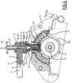
- the grinding plate 28 is removed and is replaced by a grinding plate 48 which has a similar structure.
- the grinding plate 48 has a series of through holes a thickness distributed over the surface of the grinding plate 48.
- the series of through holes have their axis parallel. to the axis of the tubing section 24.25.
- the grinding plate 48 is in a second position at the level of the first end 241 of the section of tubing 24,25.
- the grinding plate 48 rests on a surface 243 of the first rim 242.
- the interfacing element 20 comprises a grinding blade 47 associated with the grinding plate 48.
- the grinding blade 47 is mounted directly to slide on the end 31 of the drive shaft 30. The latter drives the grinding blade 47 during a rotational movement. Again, the grinding blade rests on the grinding plate 47, upstream of the latter in the direction of flow E of the mass. of meat V.
- a guide cone 29 is mounted coaxially and extending in the upper part 24 of the section of tubing 24,25.
- the role of the first part 24 of frustoconical shape of the tube section 24,25, assisted by the guide cone 29, is to guide and tighten the fibers F of minced meat at the outlet of the grinding plate 48 so that the minced meat fibers F are substantially parallel to each other and tight against each other so as to form a coherent set of parallel minced meat fibers.
- the second cylindrical part serves to guide the coherent set of fibers forward, possibly allowing a additional arrangement of minced meat fibers as a whole.
- section of tubing 24, 25 is an open duct so that the coherent assembly of parallel fibers flows freely and without disturbance along the second part of the section of tubing and leaves the second end 201 in the mold 247., This unlike the system described in Figure 14 of the document WO2015 / 012690 , in which an additional perforated plate is positioned at the second end.
- the coherent set of minced meat fibers is introduced into the cavity 140 of the mold 12.
- the minced steak thus produced then comprises meat fibers in the direction of the thickness of the patty forming the minced steak in order to form a minced steak. says “like at home”.
- the system further comprises means for cutting the set of fibers F once the cavity 140, 245 has been filled.
- means for cutting the set of fibers F For example, a cable or a cutting blade is moved through the fiber assembly after filling and before the mold is moved from its filling position to a demoulding position of the ground steak thus formed.
- the remainder of the operation of the system for forming patties 10 according to the disclosure in this second configuration is the same as in the first configuration previously described.
- FIG. 6 is illustrated a variant of the system for forming minced steaks 10 according to invention.
- This variant embodiment of the system for forming minced steaks 10 according to the invention differs from the mode previously described in that the drum-type mold is replaced by a drawer mold 240, also known per se.
- the molding of the shape of the minced steak S to be produced is carried out in cavities 245 which are filled, here, from below.
- a mold release system 246 then makes it possible to unmold and drop the minced steak S produced on the conveyor 13, following a movement D of the drawer 240 of the mold.
- the previously described interfacing element 20 is then located in the extension of the conveyor 13, as illustrated in figure 6 .
- interfacing element 20 is illustrated in the second previously described configuration of the system for forming minced steaks 10 according to the invention, in relation to the figures 4 and 5 .
- the interfacing element 20 according to the first configuration described above of the system for forming minced steaks 10 according to the invention in relation to the figures 2 and 3 can be used in the same way with a 240 drawer mold.
- FIG. 7 With reference to figures 7, 8a and 8b , we will describe a second variant embodiment of a system for forming hamburger steaks according to the invention.
- This variant embodiment is based on the system for forming minced steaks described with reference to figure 6 .
- it can be adapted to work with a rotary drum type mold as shown in figure 4 .
- the S steaks that are formed here are in the form of parallelepipedal blocks.
- a mold 247 mounted in a drawer 240 or other movable mold member has a series of cavities 245 for receiving the ground meat.
- the series of cavities comprises nine cavities 246 distributed to form a square of three by three cavities.
- the interfacing element 20 is similar to the second configuration described above of the system for forming minced steaks 10 according to the invention in relation to the figures 4 and 5 .
- the lower part 25 of the section of tubing 24,25 comprises a die 400, 450 which makes it possible to separate the stream of minced meat E formed by the assembly of minced meat fibers originating from the first frustoconical portion 24 into several injection streams.
- the section size of the injection flows 410 is carried out within the die 400, 450 by walls 411, 412 and 451.
- these walls have a bevelled upper edge so as to form a knife allowing a easy separation of the stream or set E of minced meat.
- the walls 411, 412 and 451 are inserted into grooves 401 extending along a generatrix of an internal wall of the die 400, 450.
- the upper bevel of the walls 411, 412, 451 extends at an angle of inclination, relative to a section plane of the die 400, 450.
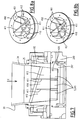
- FIG 9 we will describe a third variant embodiment of a system for forming hamburger steaks according to the disclosure.
- This variant embodiment is based, like the preceding one, on the system for forming minced steaks described with reference to figure 6 .
- it can be adapted to work with a rotary drum type mold as shown in figure 4 .
- a mold 247 mounted in a drawer 240 comprises a series of cavities 245, here substantially spherical, for receiving the minced meat.
- the series of cavities comprises six cavities 245 distributed to form two parallel rows of three cavities each.
- the interfacing element 20 is, again, similar to the previously described first configuration of the system for forming minced steaks 10 according to the disclosure in relation to the figures 2 and 3 .
- the lower part 25 of the tubing section 24,25 ends in a die 300 which makes it possible to separate the stream of minced meat E into several injection streams 310, here six in number, the dimensions of which in section of a end 320 correspond to those of the cavities 245 of the mold 247. Therefore, at the time of the formation of the steaks S, an injection flow 310 is found opposite a cavity 245 of the mold 247.
- the cross-sectional dimensioning of the flows injection 310 is produced within the die 300 by tapered tubes.
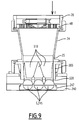
- FIG 10 we will describe a fourth alternative embodiment of a system for forming hamburger steaks according to the disclosure.
- This variant embodiment is based, like the previous ones, on the system for forming minced steaks described with reference to figure 6 .
- it can be adapted to work with a rotary drum type mold as shown in figure 4 .
- the steaks S formed are in the form of a pancake having recesses passing through a thickness of the pancake.
- the cake is round and has three recesses in shape of eyes and mouth to represent an emoticon.
- a mold 247 mounted in a drawer 240 comprises a cavity 245 for receiving the minced meat as well as protuberances 248 projecting from a bottom of the cavity 245 and corresponding to the recesses to be made in the pancake.
- the interfacing element 20 is, again, similar to the previously described first configuration of the system for forming minced steaks 10 according to the disclosure in relation to the figures 2 and 3 .
- the lower part 25 of the tubing section 24,25 ends in a die 500 which makes it possible to form the stream of minced meat E into an injection stream, the section of which, at the outlet of the interfacing element 20, is similar to a section of the steak S to be formed in the mold 247.
- the die 500 comprises a series of cores 501 and 502 which extend parallel to the stream of minced meat E and substantially perpendicular to a section of the die 500.
- the cores 501 and 502 have a lower end which is positioned opposite the associated protuberance 248, once the mold 247 is in the filling position.
- the cores 501 and 502 extend longitudinally through the section of tubing 24,25 so that an opposite end of the cores comes into contact with the grinding plate 48. Fastening means of this opposite end are provided for fixing the cores 501 and 502 on the grinding plate 48.
- the cores 501 and 502 are shorter, their opposite end then being tapered, so as not to extend or over a very short distance in the section of tubing 24, 25.
- the cores 501 and 502 are then held in place in the die 500 by thin arms extending in a section plane of the die 500, connecting the cores 501 and 502 to an internal wall of the die 500.
- All the connections of the supply line 3 on the inlet 21 of the interfacing element 20, of the elbow on the first end 241 of the section of tubing 24,25 and of the second end 201 of the section of tubing 24.25 in the inlet 121 of the mold is performed in a simple and rapid manner: for example by fitting and / or portion of a quarter or eighth turn type turn.
- This allows rapid disassembly and reassembly of the system to form minced steaks 10 according to the invention upon a change of configuration. It is the same for the establishment of the grinding plate 28 or 48 and its associated grinding blade 27 or 47 as described above.
- it is simple and quick to change on a system for forming chopped steaks 10 according to the invention the variant of chopped steaks to be prepared.
- the positioning of the grinding plate 28, 48 has been described at the level of flanges 242, 251 forming means for retaining the grinding plate and located at the ends of the tube section 24,25, it It is possible to provide other retaining means distributed discretely along the pipe section 24.25 between the first end 241 and the second end 201 depending on the distribution of the fibers F of minced meat within the volume of the 140.245 molding cavity.
- the supply line 3 is directly connected to the first end of the section of tubing 24,25.
- the grinding blade 27,47 is not necessary for the preparation and may not be mounted. , the grinding plate 28,48 then being used alone. An injection pressure supplied by the feed pump is then sufficient to pass the mass of meat through the grinding plate.
- the latter further comprises means for cutting the fibers F injected into the cavity 140, 245 of the mold 12 in order to level the hamburger in progress. preparation so as to minimize a change in the arrangement of the fibers F in the minced steak when the cavity 140,245 is moved after an injection.
- These cutting means are conveniently located just above the entrance to the cavity 140,245, downstream of the grinding plate.
- these cutting means can be a series of cutting wires stretched parallel to the axis of rotation of the drum 14 across the entrance to the cavity 140.
- these cutting means can be a blade. or a knife arranged so as to cross while leveling a section of the entrance to the cavity.
Landscapes
- Life Sciences & Earth Sciences (AREA)
- Engineering & Computer Science (AREA)
- Wood Science & Technology (AREA)
- Zoology (AREA)
- Food Science & Technology (AREA)
- Meat, Egg Or Seafood Products (AREA)
- Processing Of Meat And Fish (AREA)
- Crushing And Pulverization Processes (AREA)
Claims (4)
- System zum Ausbilden von Hacksteaks (10) ausgehend von einer Fleischmasse (V), umfassend:- eine Form (12; 240) mit wenigstens einem Hohlraum (140; 245) zur Ausbildung eines Hacksteaks;- eine Zufuhrleitung (3) für die Fleischmasse in Richtung der Form,dadurch gekennzeichnet, dass das System außerdem ein Interface-Element (20) zwischen der Zufuhrleitung und die Form umfasst, welches aufweist:- einen Rohrabschnitt (24,25) mit einem ersten Ende (241), welches mit einem Ausgang der Zufuhrleitung verbunden ist, und einem entgegengesetzten zweiten Ende (201), welches mit einem Eingang der Form verbunden ist;- eine Zerkleinerungsplatte (28; 48), welche auf Höhe des ersten Endes angebracht ist, wobei diese Zerkleinerungsplatte aufweist:
eine Reihe von Durchgangsöffnungen, die sich durch eine Dicke erstrecken und über die Oberfläche der Zerkleinerungsplatte verteilt sind, wobei die Reihe von Ausgangsöffnungen ihre Achse parallel zu einer Achse des Rohrabschnitts haben;- eine Zerkleinerungsklinge (27; 47), welche mit der Zerkleinerungsplatte verknüpft und vorgelagert zu der Letzteren angebracht ist;und wobei:- der Rohrabschnitt - nachgelagert zu der Zerkleinerungsplatte - einen ersten Teil (24) mit kegelstumpfartiger Form aufweist, welche Hackfleischfasern an dem Ausgang der Zerkleinerungsplatte aufnimmt, derart eingerichtet, um ein Einzwängen der Hackfleischfasern zu ermöglichen, so dass die Hackfleischfasern im Wesentlichen parallel zueinander und gegeneinander gedrückt werden, so dass eine zusammenhängende Anordnung von parallelen Fasern gebildet wird,- der Rohrabschnitt - nachgelagert zu dem ersten Teil (24) und benachbart zu diesem ersten Teil - einen zweiten Teil (25) mit einem im Wesentlichen konstanten Querschnitt, insbesondere mit im Wesentlichen rotationzylindrischer Form, aufweist, welcher auf Höhe des zweiten Endes endet,- der Rohrabschnitt eine offene Leitung ist, so dass die zusammenhängende Anordnung von parallelen Fasern frei und ohne Störung entlang des zweiten Teils des Rohrabschnitt fließt und aus dem zweiten Ende in die Form austritt,- der Rohrabschnitt einem Führungskonus (29) aufweist, welcher Führungskonus koaxial mit und sich in den ersten Teil (24) des Rohrabschnitts erstreckend angebracht ist,- ein Kniestück (23) abnehmbar montiert an dem ersten Ende des Rohrabschnitts angebracht ist,
wobei das Interface-Element umfasst:
entkuppelbare Mittel zum Antrieb (22, 30, 31, 26) in Rotation der Zerkleinerungsklinge, wobei die Mittel zum Antrieb an dem Kniestück angebracht sind, eine Antriebsachse (30,26) sich in dem Kniestück auf mit dem Rohrabschnitt koaxiale Weise erstreckt, und die Zerkleinerungsklinge 47 an dem Ende 31 der Antriebsachse 30 angebracht ist. - System nach Anspruch 1, dadurch gekennzeichnet, dass:- die Zerkleinerungsklinge beweglich in Anlehnung an der Zerkleinerungsplatte angebracht ist, und gleitend beweglich an den Mitteln zum Antrieb angebracht ist, und/oder- der Hohlraum der Form beweglich bezüglich des Eingangs der Form ist.
- System nach einem der Ansprüche 1 oder 2, dadurch gekennzeichnet, dass der Hohlraum der Form beweglich bezüglich des Eingangs der Form ist, und das sie außerdem Mittel zur Steuerung einer Injektion der Fleischmasse in den Hohlraum der Form aufweist, welche derart eingerichtet sind, dass die Injektion während einer sehr starken Verzögerung des Hohlraums der Form erfolgt.
- System nach einem der Ansprüche 1 - 3, dadurch gekennzeichnet, dass:- sie außer dem Mittel zum Schneiden der in den Hohlraum (140, 245) injizierten Fasern (F) aufweist, welche derart eingerichtet sind, dass das Hacksteak im Bearbeitungsverlauf bei einer Bewegung des Hohlraums eingeebnet wird, und/oder- das Element zu Kopplung auf Höhe des zweiten Endes (201) des Rohrabschnitt (24,25) eine Verzweigung (300, 400, 450, 500) zur Erzeugung einer Reihe Injektionsflüssen (310, 410) in eine Form mit einer Reihe von mehreren Hohlräumen 245 aufweist.
Applications Claiming Priority (2)
| Application Number | Priority Date | Filing Date | Title |
|---|---|---|---|
| FR1560316A FR3042948B1 (fr) | 2015-10-28 | 2015-10-28 | Systeme pour former des steaks haches |
| PCT/FR2016/052825 WO2017072471A1 (fr) | 2015-10-28 | 2016-10-28 | Système et procédé pour former des steaks hachés |
Publications (2)
| Publication Number | Publication Date |
|---|---|
| EP3367802A1 EP3367802A1 (de) | 2018-09-05 |
| EP3367802B1 true EP3367802B1 (de) | 2021-03-31 |
Family
ID=55542767
Family Applications (1)
| Application Number | Title | Priority Date | Filing Date |
|---|---|---|---|
| EP16809952.1A Active EP3367802B1 (de) | 2015-10-28 | 2016-10-28 | System zum formen von hacksteacks |
Country Status (7)
| Country | Link |
|---|---|
| US (1) | US11006641B2 (de) |
| EP (1) | EP3367802B1 (de) |
| JP (1) | JP2019503651A (de) |
| BR (1) | BR112018008554A2 (de) |
| DK (1) | DK3367802T3 (de) |
| FR (1) | FR3042948B1 (de) |
| WO (1) | WO2017072471A1 (de) |
Families Citing this family (4)
| Publication number | Priority date | Publication date | Assignee | Title |
|---|---|---|---|---|
| US12239147B2 (en) * | 2011-09-12 | 2025-03-04 | Formtec, Llc. | Formed food product |
| EP4025059A1 (de) * | 2019-09-03 | 2022-07-13 | GEA Food Solutions Bakel B.V. | Automatisiertes lebens-/futtermittelmassentransportsystem |
| CN115279190B (zh) | 2020-03-10 | 2023-11-21 | 马瑞奥深加工私人有限公司 | 从大量可泵送纤维食品材料生产三维产品 |
| WO2022207722A2 (en) | 2021-03-31 | 2022-10-06 | Marel Further Processing B.V. | System for forming moulded meat products |
Family Cites Families (18)
| Publication number | Priority date | Publication date | Assignee | Title |
|---|---|---|---|---|
| US2630458A (en) * | 1951-06-26 | 1953-03-03 | Dow Chemical Co | 3-alkyl-2,2'-dihydroxy-3',5,5'-trihalodiphenylmethanes |
| US3535735A (en) * | 1968-02-16 | 1970-10-27 | Campbell Soup Co | Extruding apparatus and system |
| BE787773A (fr) * | 1971-08-24 | 1973-02-19 | Unilever Nv | Moulage de produits alimentaires |
| US3857989A (en) * | 1973-09-27 | 1974-12-31 | King Bartolotta Inc | Method and apparatus for preparing an animal food product |
| US4068008A (en) * | 1974-01-28 | 1978-01-10 | Rca Corporation | Food product extrusion apparatus and method |
| US4205415A (en) * | 1974-01-28 | 1980-06-03 | Rca Corporation | Food product extrusion apparatus |
| US4422372A (en) * | 1981-11-12 | 1983-12-27 | Gerber Products Company | Food extruder |
| US4700899A (en) * | 1985-10-18 | 1987-10-20 | Marlen Research Corporation | Continuous vacuum grinding method and apparatus |
| WO1987002549A1 (fr) * | 1985-10-31 | 1987-05-07 | Baechtold Walter | Dispositif pour la fabrication de produits formes a base de viande |
| US4747342A (en) * | 1986-12-31 | 1988-05-31 | Marlen Research Corporation | Anaerobic meat emulsification apparatus |
| US5030164A (en) * | 1989-09-12 | 1991-07-09 | Hollymatic Corporation | Method and machine for making food patties |
| US5021025A (en) * | 1989-09-12 | 1991-06-04 | Wagner Richard C | Method and machine for making food patties |
| NL1020942C2 (nl) | 2002-06-26 | 2003-12-30 | Stork Titan Bv | Vorminrichting. |
| US8613615B2 (en) * | 2010-07-20 | 2013-12-24 | Formax, Inc. | Patty-forming apparatus with bottom feed and rotary pump |
| US9220293B2 (en) * | 2012-07-03 | 2015-12-29 | Paul Colosimo | Apparatus for forming a food product |
| BR112015001594B1 (pt) * | 2012-07-27 | 2021-01-19 | Marel Townsend Further Processing B.V. | método e sistema para moldar bolos de alimento |
| NL2011222C2 (en) * | 2013-07-25 | 2015-01-27 | Marel Townsend Further Proc Bv | Moulding food products from a pumpable foodstuff mass. |
| NL2011902C2 (nl) * | 2013-12-05 | 2015-06-08 | Caps Internat B V | Klem voor het vastklemmen van een koord onder invloed van spanning in het koord. |
-
2015
- 2015-10-28 FR FR1560316A patent/FR3042948B1/fr active Active
-
2016
- 2016-10-28 EP EP16809952.1A patent/EP3367802B1/de active Active
- 2016-10-28 WO PCT/FR2016/052825 patent/WO2017072471A1/fr not_active Ceased
- 2016-10-28 US US15/771,686 patent/US11006641B2/en active Active
- 2016-10-28 DK DK16809952.1T patent/DK3367802T3/da active
- 2016-10-28 BR BR112018008554A patent/BR112018008554A2/pt not_active IP Right Cessation
- 2016-10-28 JP JP2018522140A patent/JP2019503651A/ja active Pending
Non-Patent Citations (1)
| Title |
|---|
| None * |
Also Published As
| Publication number | Publication date |
|---|---|
| US20190116814A1 (en) | 2019-04-25 |
| WO2017072471A1 (fr) | 2017-05-04 |
| EP3367802A1 (de) | 2018-09-05 |
| US11006641B2 (en) | 2021-05-18 |
| DK3367802T3 (da) | 2021-06-14 |
| JP2019503651A (ja) | 2019-02-14 |
| FR3042948B1 (fr) | 2017-12-22 |
| BR112018008554A2 (pt) | 2018-10-23 |
| FR3042948A1 (fr) | 2017-05-05 |
Similar Documents
| Publication | Publication Date | Title |
|---|---|---|
| EP3367802B1 (de) | System zum formen von hacksteacks | |
| EP3037006B1 (de) | Herstellungsverfahren von gefüllten lebensmitteln, und entsprechende anlage | |
| EP2139343B1 (de) | Vorrichtung zur herstellung texturierter teile von lebensmittelprodukten | |
| EP2161200A1 (de) | Vorrichtung zum Aufsetzen von Muffen auf durchlaufende Gegenstände | |
| EP0373246B1 (de) | Formmaschine für Speiseeis | |
| WO1991004679A1 (fr) | Machine et procede pour le traitement en continu de surface d'articles de grosseur reduite | |
| CA2885887C (fr) | Dispositif de prehension d'au moins un produit deformable | |
| EP0040349B1 (de) | Auslass- und Dekorierdüse für Feingebäck und Dessert | |
| EP0362099B1 (de) | Vorrichtung zum kontinuierlichen Herstellen von im wesentlichen würfelförmigen Fleischstücken | |
| EP0469972B1 (de) | Vorrichtung zum Bedecken einer horizontalen Oberfläche, wie eines Backbleches mit einem fliessfähigen Teig, insbesondere eines ungekochten essbaren Teiges | |
| EP2222450B1 (de) | Vorrichtung und Verfahren zur Herstellung einer Lauffläche | |
| BE1003871A3 (fr) | Mecanisme a pompes combinees, bloc de montage pour ce mecanisme et machine de poussage de viande sous enveloppe l'utilisant. | |
| EP3708005B1 (de) | Gerät und herstellungsverfahren eines konditoreiprodukts in form eines konus, und entsprechendes konditoreiprodukt | |
| FR2591672A3 (fr) | Pompe rotative pour l'ensachage comprenant un systeme perfectionne d'extraction de l'air | |
| EP0570313A1 (de) | Coextrusionsvorrichtung zur Herstellung von einen Zweifarbenstab aus gekochten Zuckern oder ähnlichen | |
| EP0748739B1 (de) | Vorrichtung zum Eindosen von Fleisch oder Fisch, insbesondere von Thunfischfilets | |
| EP3744180B1 (de) | Verfahren zum verpacken von hackfleisch, und anlage zur umsetzung dieses verfahrens | |
| WO2025062287A1 (fr) | Dispositif d'impression 3d alimentaire | |
| EP3873216B1 (de) | Drück-form-vorrichtung und system zur kontinuierlichen herstellung von in beutelform coextrudierten lebensmittelprodukten | |
| EP2781162A1 (de) | Mehrfachdüsen-Ausgabevorrichtung für Lebensmittelprodukt | |
| EP3414071A1 (de) | Vorrichtung zum kontinuierlichen dosieren eines kunststoffmaterials, insbesondere für eine einheit zur herstellung von komponenten aus kunststoff oder dergleichen | |
| FR2866705A1 (fr) | Dispositif de dosage d'un liquide a l'interieur d'un contenant et procede associe | |
| CA2515809A1 (fr) | Extrudeuse pour la fabrication de particules spheroidales ou spheroides | |
| EP3714696A2 (de) | Anlage für die herstellung von macaronschalen | |
| FR2484321A1 (fr) | Perfectionnements aux dispositifs d'entrainement de produits pateux tels que les mortiers |
Legal Events
| Date | Code | Title | Description |
|---|---|---|---|
| STAA | Information on the status of an ep patent application or granted ep patent |
Free format text: STATUS: UNKNOWN |
|
| STAA | Information on the status of an ep patent application or granted ep patent |
Free format text: STATUS: THE INTERNATIONAL PUBLICATION HAS BEEN MADE |
|
| PUAI | Public reference made under article 153(3) epc to a published international application that has entered the european phase |
Free format text: ORIGINAL CODE: 0009012 |
|
| STAA | Information on the status of an ep patent application or granted ep patent |
Free format text: STATUS: REQUEST FOR EXAMINATION WAS MADE |
|
| 17P | Request for examination filed |
Effective date: 20180426 |
|
| AK | Designated contracting states |
Kind code of ref document: A1 Designated state(s): AL AT BE BG CH CY CZ DE DK EE ES FI FR GB GR HR HU IE IS IT LI LT LU LV MC MK MT NL NO PL PT RO RS SE SI SK SM TR |
|
| AX | Request for extension of the european patent |
Extension state: BA ME |
|
| RIN1 | Information on inventor provided before grant (corrected) |
Inventor name: LE PAIH, BERTRAND Inventor name: PIERRE, YOHANN Inventor name: MEULENDIJKS, JOHANNES MARTINUS Inventor name: GRILL, JEAN NOEL Inventor name: LE PAIH, JACQUES Inventor name: MESKENDAHL, DIRK |
|
| DAV | Request for validation of the european patent (deleted) | ||
| DAX | Request for extension of the european patent (deleted) | ||
| STAA | Information on the status of an ep patent application or granted ep patent |
Free format text: STATUS: EXAMINATION IS IN PROGRESS |
|
| 17Q | First examination report despatched |
Effective date: 20190329 |
|
| GRAP | Despatch of communication of intention to grant a patent |
Free format text: ORIGINAL CODE: EPIDOSNIGR1 |
|
| STAA | Information on the status of an ep patent application or granted ep patent |
Free format text: STATUS: GRANT OF PATENT IS INTENDED |
|
| INTG | Intention to grant announced |
Effective date: 20210112 |
|
| GRAS | Grant fee paid |
Free format text: ORIGINAL CODE: EPIDOSNIGR3 |
|
| GRAA | (expected) grant |
Free format text: ORIGINAL CODE: 0009210 |
|
| STAA | Information on the status of an ep patent application or granted ep patent |
Free format text: STATUS: THE PATENT HAS BEEN GRANTED |
|
| AK | Designated contracting states |
Kind code of ref document: B1 Designated state(s): AL AT BE BG CH CY CZ DE DK EE ES FI FR GB GR HR HU IE IS IT LI LT LU LV MC MK MT NL NO PL PT RO RS SE SI SK SM TR |
|
| REG | Reference to a national code |
Ref country code: GB Ref legal event code: FG4D Free format text: NOT ENGLISH Ref country code: CH Ref legal event code: EP |
|
| REG | Reference to a national code |
Ref country code: AT Ref legal event code: REF Ref document number: 1375902 Country of ref document: AT Kind code of ref document: T Effective date: 20210415 |
|
| REG | Reference to a national code |
Ref country code: DE Ref legal event code: R096 Ref document number: 602016055336 Country of ref document: DE |
|
| REG | Reference to a national code |
Ref country code: IE Ref legal event code: FG4D Free format text: LANGUAGE OF EP DOCUMENT: FRENCH |
|
| REG | Reference to a national code |
Ref country code: DK Ref legal event code: T3 Effective date: 20210610 |
|
| REG | Reference to a national code |
Ref country code: SE Ref legal event code: TRGR |
|
| REG | Reference to a national code |
Ref country code: NL Ref legal event code: FP |
|
| REG | Reference to a national code |
Ref country code: LT Ref legal event code: MG9D |
|
| PG25 | Lapsed in a contracting state [announced via postgrant information from national office to epo] |
Ref country code: BG Free format text: LAPSE BECAUSE OF FAILURE TO SUBMIT A TRANSLATION OF THE DESCRIPTION OR TO PAY THE FEE WITHIN THE PRESCRIBED TIME-LIMIT Effective date: 20210630 Ref country code: NO Free format text: LAPSE BECAUSE OF FAILURE TO SUBMIT A TRANSLATION OF THE DESCRIPTION OR TO PAY THE FEE WITHIN THE PRESCRIBED TIME-LIMIT Effective date: 20210630 Ref country code: FI Free format text: LAPSE BECAUSE OF FAILURE TO SUBMIT A TRANSLATION OF THE DESCRIPTION OR TO PAY THE FEE WITHIN THE PRESCRIBED TIME-LIMIT Effective date: 20210331 Ref country code: HR Free format text: LAPSE BECAUSE OF FAILURE TO SUBMIT A TRANSLATION OF THE DESCRIPTION OR TO PAY THE FEE WITHIN THE PRESCRIBED TIME-LIMIT Effective date: 20210331 |
|
| PG25 | Lapsed in a contracting state [announced via postgrant information from national office to epo] |
Ref country code: RS Free format text: LAPSE BECAUSE OF FAILURE TO SUBMIT A TRANSLATION OF THE DESCRIPTION OR TO PAY THE FEE WITHIN THE PRESCRIBED TIME-LIMIT Effective date: 20210331 Ref country code: LV Free format text: LAPSE BECAUSE OF FAILURE TO SUBMIT A TRANSLATION OF THE DESCRIPTION OR TO PAY THE FEE WITHIN THE PRESCRIBED TIME-LIMIT Effective date: 20210331 |
|
| REG | Reference to a national code |
Ref country code: AT Ref legal event code: MK05 Ref document number: 1375902 Country of ref document: AT Kind code of ref document: T Effective date: 20210331 |
|
| PG25 | Lapsed in a contracting state [announced via postgrant information from national office to epo] |
Ref country code: CZ Free format text: LAPSE BECAUSE OF FAILURE TO SUBMIT A TRANSLATION OF THE DESCRIPTION OR TO PAY THE FEE WITHIN THE PRESCRIBED TIME-LIMIT Effective date: 20210331 Ref country code: EE Free format text: LAPSE BECAUSE OF FAILURE TO SUBMIT A TRANSLATION OF THE DESCRIPTION OR TO PAY THE FEE WITHIN THE PRESCRIBED TIME-LIMIT Effective date: 20210331 Ref country code: LT Free format text: LAPSE BECAUSE OF FAILURE TO SUBMIT A TRANSLATION OF THE DESCRIPTION OR TO PAY THE FEE WITHIN THE PRESCRIBED TIME-LIMIT Effective date: 20210331 Ref country code: AT Free format text: LAPSE BECAUSE OF FAILURE TO SUBMIT A TRANSLATION OF THE DESCRIPTION OR TO PAY THE FEE WITHIN THE PRESCRIBED TIME-LIMIT Effective date: 20210331 Ref country code: SM Free format text: LAPSE BECAUSE OF FAILURE TO SUBMIT A TRANSLATION OF THE DESCRIPTION OR TO PAY THE FEE WITHIN THE PRESCRIBED TIME-LIMIT Effective date: 20210331 |
|
| PG25 | Lapsed in a contracting state [announced via postgrant information from national office to epo] |
Ref country code: IS Free format text: LAPSE BECAUSE OF FAILURE TO SUBMIT A TRANSLATION OF THE DESCRIPTION OR TO PAY THE FEE WITHIN THE PRESCRIBED TIME-LIMIT Effective date: 20210731 Ref country code: PL Free format text: LAPSE BECAUSE OF FAILURE TO SUBMIT A TRANSLATION OF THE DESCRIPTION OR TO PAY THE FEE WITHIN THE PRESCRIBED TIME-LIMIT Effective date: 20210331 Ref country code: PT Free format text: LAPSE BECAUSE OF FAILURE TO SUBMIT A TRANSLATION OF THE DESCRIPTION OR TO PAY THE FEE WITHIN THE PRESCRIBED TIME-LIMIT Effective date: 20210802 Ref country code: RO Free format text: LAPSE BECAUSE OF FAILURE TO SUBMIT A TRANSLATION OF THE DESCRIPTION OR TO PAY THE FEE WITHIN THE PRESCRIBED TIME-LIMIT Effective date: 20210331 Ref country code: SK Free format text: LAPSE BECAUSE OF FAILURE TO SUBMIT A TRANSLATION OF THE DESCRIPTION OR TO PAY THE FEE WITHIN THE PRESCRIBED TIME-LIMIT Effective date: 20210331 |
|
| REG | Reference to a national code |
Ref country code: DE Ref legal event code: R097 Ref document number: 602016055336 Country of ref document: DE |
|
| PG25 | Lapsed in a contracting state [announced via postgrant information from national office to epo] |
Ref country code: AL Free format text: LAPSE BECAUSE OF FAILURE TO SUBMIT A TRANSLATION OF THE DESCRIPTION OR TO PAY THE FEE WITHIN THE PRESCRIBED TIME-LIMIT Effective date: 20210331 Ref country code: ES Free format text: LAPSE BECAUSE OF FAILURE TO SUBMIT A TRANSLATION OF THE DESCRIPTION OR TO PAY THE FEE WITHIN THE PRESCRIBED TIME-LIMIT Effective date: 20210331 |
|
| PLBE | No opposition filed within time limit |
Free format text: ORIGINAL CODE: 0009261 |
|
| STAA | Information on the status of an ep patent application or granted ep patent |
Free format text: STATUS: NO OPPOSITION FILED WITHIN TIME LIMIT |
|
| 26N | No opposition filed |
Effective date: 20220104 |
|
| REG | Reference to a national code |
Ref country code: CH Ref legal event code: PL |
|
| PG25 | Lapsed in a contracting state [announced via postgrant information from national office to epo] |
Ref country code: IS Free format text: LAPSE BECAUSE OF FAILURE TO SUBMIT A TRANSLATION OF THE DESCRIPTION OR TO PAY THE FEE WITHIN THE PRESCRIBED TIME-LIMIT Effective date: 20210731 |
|
| REG | Reference to a national code |
Ref country code: BE Ref legal event code: MM Effective date: 20211031 |
|
| PG25 | Lapsed in a contracting state [announced via postgrant information from national office to epo] |
Ref country code: MC Free format text: LAPSE BECAUSE OF FAILURE TO SUBMIT A TRANSLATION OF THE DESCRIPTION OR TO PAY THE FEE WITHIN THE PRESCRIBED TIME-LIMIT Effective date: 20210331 |
|
| PG25 | Lapsed in a contracting state [announced via postgrant information from national office to epo] |
Ref country code: LU Free format text: LAPSE BECAUSE OF NON-PAYMENT OF DUE FEES Effective date: 20211028 Ref country code: IT Free format text: LAPSE BECAUSE OF FAILURE TO SUBMIT A TRANSLATION OF THE DESCRIPTION OR TO PAY THE FEE WITHIN THE PRESCRIBED TIME-LIMIT Effective date: 20210331 Ref country code: BE Free format text: LAPSE BECAUSE OF NON-PAYMENT OF DUE FEES Effective date: 20211031 |
|
| PG25 | Lapsed in a contracting state [announced via postgrant information from national office to epo] |
Ref country code: LI Free format text: LAPSE BECAUSE OF NON-PAYMENT OF DUE FEES Effective date: 20211031 Ref country code: CH Free format text: LAPSE BECAUSE OF NON-PAYMENT OF DUE FEES Effective date: 20211031 |
|
| PG25 | Lapsed in a contracting state [announced via postgrant information from national office to epo] |
Ref country code: IE Free format text: LAPSE BECAUSE OF NON-PAYMENT OF DUE FEES Effective date: 20211028 |
|
| PG25 | Lapsed in a contracting state [announced via postgrant information from national office to epo] |
Ref country code: HU Free format text: LAPSE BECAUSE OF FAILURE TO SUBMIT A TRANSLATION OF THE DESCRIPTION OR TO PAY THE FEE WITHIN THE PRESCRIBED TIME-LIMIT; INVALID AB INITIO Effective date: 20161028 |
|
| P01 | Opt-out of the competence of the unified patent court (upc) registered |
Effective date: 20230514 |
|
| PG25 | Lapsed in a contracting state [announced via postgrant information from national office to epo] |
Ref country code: CY Free format text: LAPSE BECAUSE OF FAILURE TO SUBMIT A TRANSLATION OF THE DESCRIPTION OR TO PAY THE FEE WITHIN THE PRESCRIBED TIME-LIMIT Effective date: 20210331 |
|
| PG25 | Lapsed in a contracting state [announced via postgrant information from national office to epo] |
Ref country code: GR Free format text: LAPSE BECAUSE OF FAILURE TO SUBMIT A TRANSLATION OF THE DESCRIPTION OR TO PAY THE FEE WITHIN THE PRESCRIBED TIME-LIMIT Effective date: 20210331 |
|
| PG25 | Lapsed in a contracting state [announced via postgrant information from national office to epo] |
Ref country code: MK Free format text: LAPSE BECAUSE OF FAILURE TO SUBMIT A TRANSLATION OF THE DESCRIPTION OR TO PAY THE FEE WITHIN THE PRESCRIBED TIME-LIMIT Effective date: 20210331 |
|
| PG25 | Lapsed in a contracting state [announced via postgrant information from national office to epo] |
Ref country code: MT Free format text: LAPSE BECAUSE OF FAILURE TO SUBMIT A TRANSLATION OF THE DESCRIPTION OR TO PAY THE FEE WITHIN THE PRESCRIBED TIME-LIMIT Effective date: 20210331 |
|
| PGFP | Annual fee paid to national office [announced via postgrant information from national office to epo] |
Ref country code: DK Payment date: 20250923 Year of fee payment: 10 |
|
| PGFP | Annual fee paid to national office [announced via postgrant information from national office to epo] |
Ref country code: NL Payment date: 20250923 Year of fee payment: 10 |
|
| PGFP | Annual fee paid to national office [announced via postgrant information from national office to epo] |
Ref country code: GB Payment date: 20250923 Year of fee payment: 10 |
|
| PGFP | Annual fee paid to national office [announced via postgrant information from national office to epo] |
Ref country code: FR Payment date: 20250923 Year of fee payment: 10 |
|
| PGFP | Annual fee paid to national office [announced via postgrant information from national office to epo] |
Ref country code: SE Payment date: 20250923 Year of fee payment: 10 |
|
| PG25 | Lapsed in a contracting state [announced via postgrant information from national office to epo] |
Ref country code: TR Free format text: LAPSE BECAUSE OF FAILURE TO SUBMIT A TRANSLATION OF THE DESCRIPTION OR TO PAY THE FEE WITHIN THE PRESCRIBED TIME-LIMIT Effective date: 20210331 |
|
| PGFP | Annual fee paid to national office [announced via postgrant information from national office to epo] |
Ref country code: DE Payment date: 20250923 Year of fee payment: 10 |