EP0748739B1 - Vorrichtung zum Eindosen von Fleisch oder Fisch, insbesondere von Thunfischfilets - Google Patents
Vorrichtung zum Eindosen von Fleisch oder Fisch, insbesondere von Thunfischfilets Download PDFInfo
- Publication number
- EP0748739B1 EP0748739B1 EP19960460022 EP96460022A EP0748739B1 EP 0748739 B1 EP0748739 B1 EP 0748739B1 EP 19960460022 EP19960460022 EP 19960460022 EP 96460022 A EP96460022 A EP 96460022A EP 0748739 B1 EP0748739 B1 EP 0748739B1
- Authority
- EP
- European Patent Office
- Prior art keywords
- conveyor
- machine
- section
- barrel
- forming
- Prior art date
- Legal status (The legal status is an assumption and is not a legal conclusion. Google has not performed a legal analysis and makes no representation as to the accuracy of the status listed.)
- Expired - Lifetime
Links
- 241000251468 Actinopterygii Species 0.000 title claims description 7
- 235000013372 meat Nutrition 0.000 title claims description 6
- 238000009924 canning Methods 0.000 title claims description 4
- 238000011144 upstream manufacturing Methods 0.000 claims description 7
- 244000043261 Hevea brasiliensis Species 0.000 claims description 2
- 229920001971 elastomer Polymers 0.000 claims description 2
- 239000000463 material Substances 0.000 claims description 2
- 229920003052 natural elastomer Polymers 0.000 claims description 2
- 229920001194 natural rubber Polymers 0.000 claims description 2
- 238000007599 discharging Methods 0.000 claims 1
- 210000000056 organ Anatomy 0.000 description 2
- 238000007493 shaping process Methods 0.000 description 2
- 229920013648 Perbunan Polymers 0.000 description 1
- 230000002411 adverse Effects 0.000 description 1
- 238000004140 cleaning Methods 0.000 description 1
- 230000000295 complement effect Effects 0.000 description 1
- 230000000694 effects Effects 0.000 description 1
- 235000013305 food Nutrition 0.000 description 1
- 230000005802 health problem Effects 0.000 description 1
- 238000002955 isolation Methods 0.000 description 1
- 238000012423 maintenance Methods 0.000 description 1
- 230000014759 maintenance of location Effects 0.000 description 1
- 210000003456 pulmonary alveoli Anatomy 0.000 description 1
- 238000012163 sequencing technique Methods 0.000 description 1
Images

Classifications
-
- A—HUMAN NECESSITIES
- A22—BUTCHERING; MEAT TREATMENT; PROCESSING POULTRY OR FISH
- A22C—PROCESSING MEAT, POULTRY, OR FISH
- A22C11/00—Sausage making ; Apparatus for handling or conveying sausage products during manufacture
- A22C11/001—Machines for making skinless sausages, e.g. Frankfurters, Wieners
-
- B—PERFORMING OPERATIONS; TRANSPORTING
- B65—CONVEYING; PACKING; STORING; HANDLING THIN OR FILAMENTARY MATERIAL
- B65B—MACHINES, APPARATUS OR DEVICES FOR, OR METHODS OF, PACKAGING ARTICLES OR MATERIALS; UNPACKING
- B65B25/00—Packaging other articles presenting special problems
- B65B25/06—Packaging slices or specially-shaped pieces of meat, cheese, or other plastic or tacky products
Definitions
- the present invention relates to a machine for canning fish or meat sliced. More specifically, it concerns a machine for processing tuna.
- the conveyor has a hand, an endless transporter whose upper strand forms a track with a semi-circular profile and, on the other share, above the downstream part of said track, a element whose profile is identical to that of carrier and forming an upper loop, the strand lower of said loop being a broken line of which the upstream part goes down to the downstream part which is adjacent to the strand of the transporter forming said track, so that a funnel section is made, then a cylindrical passage section enveloping the upstream part of the tunnel intended to cooperate with a alveolus.
- the carrier and the item each are made up of two chains, the links are associated in pairs to wear by through transverse arms the bases of half rings whose ends are in profile complementary.
- the conveyor belts consisting of a plurality of half-rings lead at risk of encrustation in the interstices separating the rings, shreds of tuna. It results quite quickly from health problems as well as risk of jamming at the exit of the transporter.
- the tuna first passes through a cell before being transferred by a piston in its box. All of this has an adverse effect on cadences.
- the object of the present invention is to overcome these disadvantages and concerns a new machine capable add high-speed tuna fillets in eliminating as much as possible the risk of jamming and allowing easier maintenance and therefore a better health guarantee.
- the invention relates to a machine of the aforementioned type in which we have directly in the cells of an original design barrel, the boxes allowing their direct filling without having to use a piston.
- the invention relates more generally to a machine for canning meat or fish previously formed into a cylindrical roll of diameter of the box of the type comprising a conveyor responsible for both transport and roll forming of the product to be put in box, said co-operating conveyor with a rotary cutter responsible for cutting at desired length of a section of said roller, the conveyor being constituted by two adjacent strands of two endless loops formed by two continuous and smooth strips of semi-circular section, the two adjacent strands forming by their concave faces with semi-circular profile one way at the entrance to the flared section conveyor gradually evolving into a corridor section cylindrical, the lower edges of said strands adjacent being joined along their entire length.
- the two bands forming said conveyor are each driven by two end pulleys, and both pulleys of each separate loop constituting the downstream end of the conveyor are located side by side and revolve around two axes, located on both sides across the longitudinal alignment axis, extending parallel in a direction perpendicular to it to create a forming area, while the two other pulleys of each loop constituting the end upstream of said conveyor are arranged side by side and rotate around two axes forming an angle between them open upwards to form an area of loading.
- the invention also relates to such a machine characterized in that, through a connecting sleeve, this conveyor cooperates with a barrel constituted by a tapered crown rotating around an axis inclined to 45 ° in the vertical plane of the axis of said sleeve connection, cells being produced peripherally on the lateral surface of the frustoconical crown itself forming an angle of 45 ° with respect to its base so that, during the rotation of said barrel around its axis, a given cell containing a empty box is positioned at first, said to loading, facing the outlet of the connecting sleeve, the bottom of the box being vertical and perpendicular to the axis of the sleeve, in a second step, says evacuation, in a position such that said bottom is in a horizontal plane.
- the conveyor 2 advances step by step and is consisting of two endless loops 7 and 8 of section semi-circular, including two adjacent strands 7a and 8a, form a track at the entrance of the conveyor (upstream) flared section (Figure 3) gradually towards the exit in a section in cylindrical corridor (figure 2) constituting the section downstream of said conveyor 2.
- the loading of the supply path formed by the adjacent strands 7a and 8a is substantially carried out in zone A of conveyor while the roll forming of said loading is carried out in zone B.
- the endless loops 7 and 8 constituting the conveyor 2 are formed by two continuous and smooth bands of semi-circular section, in other words which have a continuous and smooth concave outer face with a semi-circular profile.
- said concave faces are opposite one another and are joined by their edge or lower edge.
- Said continuous bands constituting the endless loops 7 and 8 are driven by two pulleys. end 9, 10 and 11, 12.
- the two pulleys 9, 11 of each separate loop 7 and 8 constitute the downstream end of the conveyor 1 and are located side by side and rotate around two vertical axes a and b, perpendicular to the 'longitudinal axis xx' of the conveyor to form a forming zone B ( Figure 2).
- the two other pulleys 10 and 12 of each loop 7 and 8 constituting the upstream end of said conveyor 1 are arranged side by side but rotate around two axes c and d forming between them an angle 3 open upwards to constitute a loading area A ( Figure 3).
- edges or lower edges of said concave faces along the adjacent strands 7a, 8a of loops 7, 8 are joined together by through a connecting chute in which they slide freely.
- the continuous and smooth endless bands of loops 7 and 8 are formed, in accordance with the invention, by a continuous ribbon of a material food grade such as natural rubber, which has said concave face with semi-circular profile, and an opposite face joined to a sole in perbunan (synthetic black rubber), the whole ribbon and sole being rigid enough to ensure the roll forming of tuna fillets and flexible enough to be able to precisely twist to form an open section (Figure 3) upstream, evolving towards a circular section downstream (figure 2). Possibly, banks are put in place in forming zone B to contain the pressure resulting from product pushing and ensuring good shaping of the tuna roll in this part of the conveyor before it is picked up for its evacuation.
- a continuous ribbon of a material food grade such as natural rubber
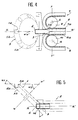
- the interface between the output of conveyor 2 and the barrel 5 is ensured by means of a sleeve 3 centered on XX ', of which the entry cone 3a has a slightly diameter higher than that of the roller facilitates the reception of the latter avoiding the jam as much as possible, this cone 3a extending into a cylindrical part, the diameter slightly smaller than that of the roller corresponds to the dimensions of the interior of boxes 6 to fill.
- the rotating barrel 5 symbolized in the figures 1 and 4 in dotted lines, consists of an element turning step by step offset from the advance of the conveyor 2.
- the periphery of the barrel 5 has cells 14 intended to receive boxes 6 open towards the exterior coming one after the other positioning facing the outlet of sleeve 3.
- the architecture and kinetics are more clearly illustrated in the figure 5.
- This ring constituting the barrel 5 rotates around an axis ww 'inclined at an angle ⁇ 2 of 45 ° relative to the horizontal, in the vertical plane of the axis xx', while all of the supporting cells 14 boxes 6 are made peripherally on the lateral surface 5a of the frustoconical crown itself forming an angle ⁇ 1 of 45 ° relative to its base 5b.
- the boxes 6 are loaded in the six o'clock hourly position on the barrel, and their evacuation in the twelve o'clock hourly position, approximately.
- each of the boxes 6 is in turn in the loading position facing the outlet of the sleeve 3 (bottom of the empty box 6 in vertical position, perpendicular to the axis xx '), then gradually straightens until standing in the discharge position (bottom of the full box 6a in the horizontal position).
- the rotary cutter 4 for its part, is with a transverse movement at the outlet of the sleeve 3 to slice a portion of the tuna roll having entered the empty box under the push of the roller.
- one of the boxes 6 is opposite the outlet of sleeve 3.
- a portion of tuna is injected into the box 6, after which the cutting member 4 passes in front of it to separate the portion.
- the barrel 5 turns one step. Simultaneously, a full box 6a is evacuated and a empty box goes into the filling position.
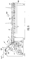
- Figure 6 illustrates the whole machine 1 according to the invention, seen from the side, as well as schematically the system ensuring synchronization movements of essential elements.
- conveyor 2 mounted on a chassis 100 supporting the two pulleys 11 and 12 as well as the strand 8 (only visible in this figure 6).
- guides 101 mark out the course of the strands from the zone A to zone B, route followed by the nets of tuna and symbolized by the arrow 102.
- Such a machine according to the invention meets requirements for ease of cleaning, given the corridor continuity (without any gaps) where transits and is rolled up the product to be box. It also meets the cadence requirements directly engaging the box to be filled with the correctly formed filling product thanks to a barrel whose architecture ensures both feeding in empty boxes, loading and evacuation when full.
- One of the preferred applications of the invention is found in the sliced tuna cannery obtained at from the fillets of this fish.
Landscapes
- Engineering & Computer Science (AREA)
- Life Sciences & Earth Sciences (AREA)
- Mechanical Engineering (AREA)
- Wood Science & Technology (AREA)
- Zoology (AREA)
- Food Science & Technology (AREA)
- Meat, Egg Or Seafood Products (AREA)
- Processing Of Meat And Fish (AREA)
Claims (8)
- Maschine zum Eindosen von Fleisch oder Fisch, das/der in eine zylindrische Rolle vorgeformt ist, deren Durchmesser demjenigen der Dose entspricht, wobei die Maschine vom Typ mit einer kontinuierlich arbeitenden Fördereinrichtung ist, die gleichzeitig für den Transport und die Rollenformung des einzudosenden Produkts zuständig ist, wobei die Fördereinrichtung mit einem drehenden Schneidorgan (4) zusammenwirkt, das für das Abschneiden von einem Teilstück der Rolle auf eine gewünschte Länge zuständig ist, wobei sich die Fördereinrichtung (2) aus zwei benachbarten Strängen (7a, 8a) zweier Endlosschleifen (7, 8) zusammensetzt, wobei die beiden benachbarten Stränge (7a, 8a) mit ihren konkaven Flächen halbkreisförmigen Profils einen Zuführungsweg zum Einlaß der Fördereinrichtung bilden, der einen erweiterten Querschnitt hat und nach und nach in einen Kanal zylindrischen Querschnitts übergeht, dadurch gekennzeichnet, daß die beiden Endlosschleifen (7, 8) aus zwei durchgehenden und glatten Bändern gebildet sind und daß die unteren Kanten (7b, 8b) der benachbarten Stränge (7a, 8a) auf ihrer ganzen Länge nebeneinanderliegend sind.
- Maschine nach Anspruch 1, dadurch gekennzeichnet, daß die beiden Bänder, die die Fördereinrichtung (2) bilden, jeweils von zwei Endriemenscheiben (9, 10 und 11, 12) angetrieben sind, und daß die beiden Riemenscheiben (9, 11) jeder einzelnen Schleife (7 und 8), die das untere Ende der Fördereinrichtung (2) bilden, Seite an Seite angeordnet sind und sich um zwei Achsen (a und b) drehen, die sich auf der einen und der anderen Seite der Längsausrichtungsachse (xx') befinden und sich parallel in senkrechter Richtung dazu erstrecken, um einen Formungsbereich (B) zu schaffen, während die beiden anderen Riemenscheiben (10, 12) jeder Schleife (7 und 8), die das obere Ende der Fördereinrichtung (2) bilden, Seite an Seite angeordnet sind und sich um zwei Achsen (c und d) drehen, die zwischen sich einen Winkel (α3) bilden, der nach oben geöffnet ist, um einen Beladebereich (A) zu bilden.
- Maschine nach einem der vorhergehenden Ansprüche, dadurch gekennzeichnet, daß die Endlosbänder der Schleifen (7, 8) aus einer Sohle aus Perbunan (schwarzem synthetischem Gummi) bestehen, die mit einem lebensmitteltauglichen Material aus Naturgummi überzogen ist.
- Maschine nach einem der vorhergehenden Ansprüche, dadurch gekennzeichnet, daß die Rolle am Auslaß der Fördereinrichtung (2) von einer Verbindungsmuffe (3) übernommen wird, die einen Einlaßquerschnitt (3a) hat, der etwas größer als der Rollendurchmesser ist, wobei dieser Querschnitt (3a) nach und nach in einen Auslaßquerschnitt übergeht, der dem Innendurchmesser der zu füllenden Dosen (6) entspricht.
- Maschine nach einem der Ansprüche 1 bis 4, dadurch gekennzeichnet, daß sie ferner eine kegelstumpfförmige Trommel (5) enthält, die an ihrem Umfang eine Vielzahl von Zellen (14) umfaßt, die zur Aufnahme der zu füllenden Dosen (6) vorgesehen sind.
- Maschine nach Anspruch 5, dadurch gekennzeichnet, daß die Trommel (5) aus einem kegelstumpfförmigen Kranz besteht, der sich um eine Achse (ww') dreht, die in Bezug auf die Horizontale entlang einem Winkel (α2) von 45° in der vertikalen Ebene der Achse (xx') der Auslaßmuffe (3) geneigt ist, wobei die Zellen (14) am Umfang an der seitlichen Fläche (5a) des kegelstumpfförmigen Kranzes ausgebildet sind, der selbst in Bezug auf seine Basis (5b) einen Winkel (α1) von 45° bildet, so daß bei der Drehung der Trommel um die Achse (ww') sich eine bestimmte Zelle (14), die eine leere Dose (6) enthält, in einer ersten Phase, der sogenannten Beladephase, gegenüber dem Auslaß der Verbindungsmuffe (3) positioniert, wobei der Dosenboden vertikal und senkrecht zur Achse (xx') ist, und in einer zweiten Phase, der sogenannten Abtransportphase, in einer Stellung, in der sich der Boden in einer horizontalen Ebene befindet.
- Maschine nach einem der vorhergehenden Ansprüche, dadurch gekennzeichnet, daß die unteren Kanten (7b, 8b) der beiden benachbarten Stränge (7a, 7b) der Schleifen (7, 8) miteinander mittels einer Verbindungsrinne verbunden sind, in der sie frei gleiten.
- Maschine nach einem der vorhergehenden Ansprüche, dadurch gekennzeichnet, daß alle Bewegungen der Fördereinrichtung (2), des Schneidorgans (4) und der Trommel (5) von ein und demselben Motor gesteuert sind.
Applications Claiming Priority (2)
| Application Number | Priority Date | Filing Date | Title |
|---|---|---|---|
| FR9507257A FR2735446B1 (fr) | 1995-06-13 | 1995-06-13 | Machine de mise en boite de viande ou de poisson, notamment de filets de thon |
| FR9507257 | 1995-06-13 |
Publications (2)
| Publication Number | Publication Date |
|---|---|
| EP0748739A1 EP0748739A1 (de) | 1996-12-18 |
| EP0748739B1 true EP0748739B1 (de) | 1999-02-24 |
Family
ID=9480109
Family Applications (1)
| Application Number | Title | Priority Date | Filing Date |
|---|---|---|---|
| EP19960460022 Expired - Lifetime EP0748739B1 (de) | 1995-06-13 | 1996-06-10 | Vorrichtung zum Eindosen von Fleisch oder Fisch, insbesondere von Thunfischfilets |
Country Status (4)
| Country | Link |
|---|---|
| EP (1) | EP0748739B1 (de) |
| DE (1) | DE69601559D1 (de) |
| ES (1) | ES2129946T3 (de) |
| FR (1) | FR2735446B1 (de) |
Cited By (1)
| Publication number | Priority date | Publication date | Assignee | Title |
|---|---|---|---|---|
| DE102015003011A1 (de) | 2015-03-06 | 2016-10-27 | ROSOMA GmbH Rostocker Sondermaschinen- und Anlagenbau | Einbringen von Fischfilets in Konservendosen |
Families Citing this family (2)
| Publication number | Priority date | Publication date | Assignee | Title |
|---|---|---|---|---|
| FR2811516B1 (fr) * | 2000-07-17 | 2002-10-18 | Sarl Prima Daniel | Procede et machine pour le remplissage d'un boyau par de la matiere alimentaire |
| FR2932774B1 (fr) * | 2008-06-18 | 2010-09-17 | Sarl Prima Daniel | Procede d'emboutement de saucisson de matiere alimentaire,et dispositif destine destine a la mise en oeuvre de ce procede |
Family Cites Families (3)
| Publication number | Priority date | Publication date | Assignee | Title |
|---|---|---|---|---|
| US2542673A (en) * | 1947-10-13 | 1951-02-20 | Fredrick A Hedwall | Sausage forming machine |
| US2669378A (en) * | 1949-10-13 | 1954-02-16 | Eben H Carruthers | Machine for packing a predetermined weight of bulk product |
| US2840121A (en) * | 1953-11-12 | 1958-06-24 | Eben H Carruthers | Machine for packing a predetermined weight of bulk products |
-
1995
- 1995-06-13 FR FR9507257A patent/FR2735446B1/fr not_active Expired - Fee Related
-
1996
- 1996-06-10 ES ES96460022T patent/ES2129946T3/es not_active Expired - Lifetime
- 1996-06-10 DE DE69601559T patent/DE69601559D1/de not_active Expired - Lifetime
- 1996-06-10 EP EP19960460022 patent/EP0748739B1/de not_active Expired - Lifetime
Cited By (1)
| Publication number | Priority date | Publication date | Assignee | Title |
|---|---|---|---|---|
| DE102015003011A1 (de) | 2015-03-06 | 2016-10-27 | ROSOMA GmbH Rostocker Sondermaschinen- und Anlagenbau | Einbringen von Fischfilets in Konservendosen |
Also Published As
| Publication number | Publication date |
|---|---|
| ES2129946T3 (es) | 1999-06-16 |
| DE69601559D1 (de) | 1999-04-01 |
| FR2735446B1 (fr) | 1997-08-14 |
| EP0748739A1 (de) | 1996-12-18 |
| FR2735446A1 (fr) | 1996-12-20 |
Similar Documents
| Publication | Publication Date | Title |
|---|---|---|
| CA2312038C (fr) | Dispositif de convoyage de produits, notamment de fruits, destine a l'alimentation d'une unite de tri desdits produits | |
| FR2614603A1 (fr) | Ensemble a machoires tournantes pour machines d'empaquetage, en particulier pour machines d'empaquetage pour emballage tubulaire du type a empaquetage continu ou analogue | |
| CH400889A (fr) | Procédé pour remplir et fermer des récipients et machine pour la mise en oeuvre de ce procédé | |
| FR2744598A1 (fr) | Procede et appareil de production d'un aliment cylindrique, et aliment cylindrique | |
| EP0748739B1 (de) | Vorrichtung zum Eindosen von Fleisch oder Fisch, insbesondere von Thunfischfilets | |
| FR2679869A1 (fr) | Machine destinee a l'emballage d'articles de dimensions universelles au moyen de morceaux d'une bande de matiere thermoretractable. | |
| EP1077891B1 (de) | Automatische ausrichtungs- und ausgabevorrichtung für werkstücke | |
| FR2605290A1 (fr) | Mandrin pour machine a pousser la viande sous boyau et cette machine | |
| FR2587593A1 (fr) | Appareillage et procede pour l'epluchage partiel du mais sweet corn frais. | |
| CH666388A5 (fr) | Procede de fabrication de cordons multi-elements pour article a fumer. | |
| FR2538223A1 (fr) | Appareil de conditionnement de produits pateux, notamment de produits alimentaires, tels que de la viande hachee | |
| EP0865733B1 (de) | Verfahren und Vorrichtung zur Herstellung von Spiessen | |
| EP0479638B1 (de) | Vorrichtung zum Entleeren von insbesondere Früchte und Gemüse enthaltenden Kästen | |
| FR2683214A1 (fr) | Dispositif servant a distribuer des doses determinees d'un produit. | |
| FR2623775A1 (fr) | Machine pour la mise en boite de viande ou de poisson en tranche | |
| FR2551206A1 (fr) | Perfectionnements aux machines a peser et a selectionner des produits de l'horticulture et similaires | |
| FR2463083A1 (fr) | Dispositif d'alimentation en conteneurs cylindriques, notamment pour machine a imprimer ces conteneurs | |
| FR2470534A1 (fr) | Machine a demouler et a rogner des fromages | |
| FR2808658A1 (fr) | Procede dispositif et installation pour confectionner un produit comestible compose de deux tranches enserrant un fourrage | |
| FR2680079A1 (fr) | Procede et dispositif pour la fabrication de fromages. | |
| LU81667A1 (fr) | Procede de conditionnement de produits pulverulents ou granuleux dans des emballages souples et installation pour la mise en oeuvre de ce procede | |
| FR2733202A1 (fr) | Dispositif de separation a l'unite de produits juxtaposes ou ampiles | |
| FR2679201A1 (fr) | Procede et dispositif pour la mise en barquette de produits divers. | |
| FR2630707A1 (fr) | Appareil et procede pour envelopper un produit et produit ainsi enveloppe | |
| EP2303029B1 (de) | Verfahren zum eindosen von nahrungsmitteln mit zylindrischer form sowie gerät zum durchführen dieses verfahrens |
Legal Events
| Date | Code | Title | Description |
|---|---|---|---|
| PUAI | Public reference made under article 153(3) epc to a published international application that has entered the european phase |
Free format text: ORIGINAL CODE: 0009012 |
|
| AK | Designated contracting states |
Kind code of ref document: A1 Designated state(s): BE DE DK ES FI GB GR IE IT NL PT SE |
|
| 17P | Request for examination filed |
Effective date: 19970206 |
|
| GRAG | Despatch of communication of intention to grant |
Free format text: ORIGINAL CODE: EPIDOS AGRA |
|
| GRAG | Despatch of communication of intention to grant |
Free format text: ORIGINAL CODE: EPIDOS AGRA |
|
| GRAH | Despatch of communication of intention to grant a patent |
Free format text: ORIGINAL CODE: EPIDOS IGRA |
|
| 17Q | First examination report despatched |
Effective date: 19980630 |
|
| GRAH | Despatch of communication of intention to grant a patent |
Free format text: ORIGINAL CODE: EPIDOS IGRA |
|
| GRAA | (expected) grant |
Free format text: ORIGINAL CODE: 0009210 |
|
| AK | Designated contracting states |
Kind code of ref document: B1 Designated state(s): BE DE DK ES FI GB GR IE IT NL PT SE |
|
| PG25 | Lapsed in a contracting state [announced via postgrant information from national office to epo] |
Ref country code: SE Free format text: THE PATENT HAS BEEN ANNULLED BY A DECISION OF A NATIONAL AUTHORITY Effective date: 19990224 Ref country code: NL Free format text: LAPSE BECAUSE OF FAILURE TO SUBMIT A TRANSLATION OF THE DESCRIPTION OR TO PAY THE FEE WITHIN THE PRESCRIBED TIME-LIMIT Effective date: 19990224 Ref country code: GR Free format text: LAPSE BECAUSE OF NON-PAYMENT OF DUE FEES Effective date: 19990224 Ref country code: GB Free format text: LAPSE BECAUSE OF NON-PAYMENT OF DUE FEES Effective date: 19990224 Ref country code: FI Free format text: LAPSE BECAUSE OF NON-PAYMENT OF DUE FEES Effective date: 19990224 |
|
| REG | Reference to a national code |
Ref country code: IE Ref legal event code: FG4D Free format text: FRENCH |
|
| REF | Corresponds to: |
Ref document number: 69601559 Country of ref document: DE Date of ref document: 19990401 |
|
| ITF | It: translation for a ep patent filed | ||
| PG25 | Lapsed in a contracting state [announced via postgrant information from national office to epo] |
Ref country code: PT Free format text: LAPSE BECAUSE OF FAILURE TO SUBMIT A TRANSLATION OF THE DESCRIPTION OR TO PAY THE FEE WITHIN THE PRESCRIBED TIME-LIMIT Effective date: 19990524 Ref country code: DK Free format text: LAPSE BECAUSE OF FAILURE TO SUBMIT A TRANSLATION OF THE DESCRIPTION OR TO PAY THE FEE WITHIN THE PRESCRIBED TIME-LIMIT Effective date: 19990524 |
|
| PG25 | Lapsed in a contracting state [announced via postgrant information from national office to epo] |
Ref country code: DE Free format text: LAPSE BECAUSE OF FAILURE TO SUBMIT A TRANSLATION OF THE DESCRIPTION OR TO PAY THE FEE WITHIN THE PRESCRIBED TIME-LIMIT Effective date: 19990526 |
|
| RAP2 | Party data changed (patent owner data changed or rights of a patent transferred) |
Owner name: COBRIMEX (SA) |
|
| REG | Reference to a national code |
Ref country code: ES Ref legal event code: FG2A Ref document number: 2129946 Country of ref document: ES Kind code of ref document: T3 |
|
| PG25 | Lapsed in a contracting state [announced via postgrant information from national office to epo] |
Ref country code: BE Free format text: LAPSE BECAUSE OF NON-PAYMENT OF DUE FEES Effective date: 19990630 |
|
| NLV1 | Nl: lapsed or annulled due to failure to fulfill the requirements of art. 29p and 29m of the patents act | ||
| GBV | Gb: ep patent (uk) treated as always having been void in accordance with gb section 77(7)/1977 [no translation filed] |
Effective date: 19990224 |
|
| PG25 | Lapsed in a contracting state [announced via postgrant information from national office to epo] |
Ref country code: IE Free format text: LAPSE BECAUSE OF NON-PAYMENT OF DUE FEES Effective date: 19991019 |
|
| REG | Reference to a national code |
Ref country code: IE Ref legal event code: FD4D |
|
| PLBE | No opposition filed within time limit |
Free format text: ORIGINAL CODE: 0009261 |
|
| STAA | Information on the status of an ep patent application or granted ep patent |
Free format text: STATUS: NO OPPOSITION FILED WITHIN TIME LIMIT |
|
| BERE | Be: lapsed |
Owner name: CIE BRETONNE DE LA COQUILLE SAINT-JACQUES S.A.- C Effective date: 19990630 |
|
| 26N | No opposition filed | ||
| PGFP | Annual fee paid to national office [announced via postgrant information from national office to epo] |
Ref country code: ES Payment date: 20100611 Year of fee payment: 15 |
|
| PGFP | Annual fee paid to national office [announced via postgrant information from national office to epo] |
Ref country code: IT Payment date: 20110527 Year of fee payment: 16 |
|
| PG25 | Lapsed in a contracting state [announced via postgrant information from national office to epo] |
Ref country code: IT Free format text: LAPSE BECAUSE OF NON-PAYMENT OF DUE FEES Effective date: 20120610 |
|
| REG | Reference to a national code |
Ref country code: ES Ref legal event code: FD2A Effective date: 20130531 |
|
| PG25 | Lapsed in a contracting state [announced via postgrant information from national office to epo] |
Ref country code: ES Free format text: LAPSE BECAUSE OF NON-PAYMENT OF DUE FEES Effective date: 20110611 |