EP2139343B1 - Vorrichtung zur herstellung texturierter teile von lebensmittelprodukten - Google Patents
Vorrichtung zur herstellung texturierter teile von lebensmittelprodukten Download PDFInfo
- Publication number
- EP2139343B1 EP2139343B1 EP08805505.8A EP08805505A EP2139343B1 EP 2139343 B1 EP2139343 B1 EP 2139343B1 EP 08805505 A EP08805505 A EP 08805505A EP 2139343 B1 EP2139343 B1 EP 2139343B1
- Authority
- EP
- European Patent Office
- Prior art keywords
- cutting
- food product
- portions
- stream
- order
- Prior art date
- Legal status (The legal status is an assumption and is not a legal conclusion. Google has not performed a legal analysis and makes no representation as to the accuracy of the status listed.)
- Not-in-force
Links
Images
Classifications
-
- A—HUMAN NECESSITIES
- A22—BUTCHERING; MEAT TREATMENT; PROCESSING POULTRY OR FISH
- A22C—PROCESSING MEAT, POULTRY, OR FISH
- A22C7/00—Apparatus for pounding, forming, or pressing meat, sausage-meat, or meat products
- A22C7/0007—Apparatus for pounding, forming, or pressing meat, sausage-meat, or meat products specially adapted for making multi-layered meat products
-
- A—HUMAN NECESSITIES
- A22—BUTCHERING; MEAT TREATMENT; PROCESSING POULTRY OR FISH
- A22C—PROCESSING MEAT, POULTRY, OR FISH
- A22C17/00—Other devices for processing meat or bones
- A22C17/0006—Cutting or shaping meat
-
- A—HUMAN NECESSITIES
- A22—BUTCHERING; MEAT TREATMENT; PROCESSING POULTRY OR FISH
- A22C—PROCESSING MEAT, POULTRY, OR FISH
- A22C17/00—Other devices for processing meat or bones
- A22C17/0006—Cutting or shaping meat
- A22C17/002—Producing portions of meat with predetermined characteristics, e.g. weight or particular dimensions
Definitions
- the present invention relates to a device for manufacturing portions of food products, and more particularly portions of food products textured from food products in pieces, including cold meat blocks in muscle.
- the chopper is associated with a flow control member said pusher, typically comprising a pump, for example pallet or piston, fed at the inlet by a hopper and whose discharge outlet is equipped with said chopper.
- said pusher typically comprising a pump, for example pallet or piston, fed at the inlet by a hopper and whose discharge outlet is equipped with said chopper.
- the patent document EP 1 509 089 describes a similar device for the manufacture of chopped steaks filled with a filling.
- the chopper is equipped at the outlet of two dispensing spouts to form a vein of minced meat and a vein of minced meat upper respectively deposited on a main conveyor and a secondary conveyor.
- the filling is deposited on the lower meat vein, and the upper meat vein is then brought to overlap the lower meat vein and the filling deposited thereon to form a filled vein of minced meat, which then passes into the meat. cutting and forming device mentioned above.
- Such devices are provided for making portions from minced meat and extruded through the grid holes of a chopper.
- the end products obtained are textured in longitudinally oriented minced meat strands, and therefore have a wired appearance.
- the object of the present invention is to provide a device for obtaining new products having a different texture.
- the present invention provides a device for the manufacture of end products having a textured appearance similar to that of the starting food product which is introduced into the pump, and in particular in the case of meat, keeping the fibrous appearance of the pieces of meat starting.
- the device according to the invention can be used for making portions from any type of food product in pieces, such as muscle meat, filleted fish, chopped vegetables such as carrots for example.
- the present invention relates to a device for producing portions of food products in pieces, in particular cold muscle meat blocks, comprising at least one pump capable of delivering at output a substantially constant flow of food product in pieces, a pipe tubular dispenser connected to the delivery outlet of said pump for receiving in its internal main passage the food product leaving the pump, and comprising at least one dispensing orifice, and cutting and forming means acting on the dispensed food product through the outlet of the dispensing pipe to form portions of food products, characterized in that said distribution pipe is equipped with a cutting system comprising at least one cutting means traversing transversely through said passage internal main of the distribution pipe, with a straight cutting edge t turned to the flow direction of the food product stream to cut the food product into at least two layers, so as to obtain textured food product portions at the outlet of the forming and cutting means.
- the dispensing system is equipped with at least one cutting means capable of cutting the flow of meat in at least two layers.
- the dispensing line is connected directly to the discharge outlet of the pump, without interposing a hash system, so that, in the case of chopped food products, a new, textured, multi-layer, multi-type final product is obtained.
- -bands and / or small pieces the outer appearance of which corresponds to the texture of the food product in starting pieces.
- the final product retains the fibrous appearance of the original meat.
- Said cutting means is a dynamic cutting means, such as for example oscillating flat blade type coupled to a reciprocating movement system, rotating circular blade, blade coupled to an ultrasonic generator, laser beam, and / or or water jet.
- said pump is a rotary piston pump type pump, comprising a stator defining a cylindrical cavity, a rotor or barrel housed in said cylindrical cavity, adapted to be rotated by a motor, said rotor comprising a set of circumferentially spaced bores, in which pistons are mounted, a mechanical cam cooperating with the pistons to cause, during the rotation of the barrel, an alternating movement of said pistons between a low position and a high position, a lid closing the cylindrical cavity, a supply port communicating with at least one cylindrical chamber formed by a cylindrical bore of the barrel and its associated piston, and intended to be in communication with a hopper, a discharge orifice adapted to come simultaneously in communication with at least two consecutive cylindrical chambers.
- the dispensing line cutting system comprises a first set of cutting means, arranged parallel to each other, for example horizontally, for cutting the food product from the pump in several layers.
- the distance between two adjacent cutting means, for example two adjacent flat blades, is for example between 1 and 20 mm, depending on the desired final product, preferably between 2 and 7 mm.
- the cutting system comprises a second set of cutting means arranged parallel to each other, downstream of the first set of cutting means, for cutting into strips each of the layers resulting from the first set of cutting means. section, the first set of cutting means and the second set of cutting means being preferably arranged perpendicular to one another.
- the distance between two adjacent cutting means is between 1 and 20 mm, preferably between 2 and 7 mm.
- each cutting means of the cutting system comprises an oscillating flat blade.
- each set of blades comprises first oscillating blades able to be displaced by a first system movement in a reciprocating movement, and second oscillating blades, interposed between the first oscillating blades, and moved by a second displacement system in a movement back and forth opposite to that of the first oscillating blades.
- the cutting and forming means consist of a cutting and forming device of a type described in the patent documents. EP 1 397 047 and EP 1 509 089 supra.
- a device comprises a forming conveyor belt for receiving a vein of food product from the distribution pipe, and along the latter, means for cutting said vein into portions, lateral forming means acting simultaneously on each side. said vein for forming the contour of said portions, and vertical forming means cooperating with said lateral forming means to impart to said portions the desired thickness.
- the dispensing line is equipped with a cutting system comprising a cutting means, such as a horizontal oscillating flat blade, arranged upstream of separating means for separating the internal main passage of the pipe in two passages.
- a cutting system comprising a cutting means, such as a horizontal oscillating flat blade, arranged upstream of separating means for separating the internal main passage of the pipe in two passages.
- said device preferably comprising a main conveyor belt for receiving the bottom vein of food product, a secondary conveyor belt continuously moving disposed above the main conveyor belt to receive the upper vein, and possibly, packing deposition means capable of depositing a liner, preferably laterally, on the lower duct, said secondary band then being able to transport and depositing said upper vein on said lower vein and the liner.
- the cutting and forming means comprise a knife, preferably rotatable, capable of slicing the food product leaving the distribution pipe, a transport belt for recovering the slices formed by said knife, and preferably, along this conveyor belt, forming means side members to form the contour of said portions, and vertical forming means for imparting to said portions the desired thickness.
- the device comprises several pumps, for example two pumps, the distribution line being connected to the discharge outlet of each pump to receive in its internal main passage the food product leaving each pump, the pumps being used to deliver different food products.
- the subject of the present invention is also a process for producing portions of food products in pieces, in particular slabs of fresh meat in muscles, characterized in that it comprises a step a) of forming a substantially constant flow of a food product in pieces in a distribution pipe, a step b) of cutting in said food product distribution pipe in at least two layers, and a step c) of cutting and forming the food product at the outlet of the distribution pipe to form portions of food product having the texture of the starting food product.
- the food product is cut into a plurality of superimposed continuous horizontal layers, for example from 1 to 20 mm thick, preferably from 2 to 7 mm thick, each horizontal layer of food product furthermore being cut into a plurality of continuous strips, 1 to 20 mm wide, preferably 2 to 7 mm wide, or strips having cross-sections of 1 to 400 mm 2 , preferably 4 to about 50 mm 2 .
- the food product at the outlet of the dispensing line is in the form of at least one continuous vein, step c) comprising cutting and shaping said vein into portions of layered food product. superimposed or in longitudinal strips.
- the food product leaving the distribution pipe is in the form of a continuous lower vein and a continuous upper vein brought into lower vein recovery, the method further comprising a step of depositing a liner on the lower vein prior to its overlap by the upper vein, to form a filled main continuous vein, wherein step c) comprises cutting and placing forming said main vein into portions of food product filled with a filling.
- step c) the food product at the outlet of the distribution line is sliced to form, after shaping portions of food product in transverse strips or in small pieces of food product.
- the invention also relates to end products obtained by the process and the manufacturing device defined above.
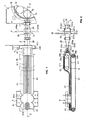
- FIGS 1 to 3 they schematically illustrate a device for manufacturing portions of food products according to a first embodiment intended in particular for the manufacture of sliced meat strips in strips or rods and provided with an interior lining, from pieces of meat , not chopped.
- the device comprises a pump 1 illustrated schematically and partially on the figure 1 , equipped at its discharge outlet 11 with a distribution pipe 2.
- said dispensing line comprises an inlet orifice 21 through which the pipe is connected to the delivery outlet of said pump for receiving in its main internal passage 23 the pieces of meat delivered by the pump, this main passage being subdivided into two parts; secondary passages 24a and 24b defining downstream in two dispensing orifices 22a, 22b, vertically offset from one another, to form a lower meat vein V'1 and an upper meat vein V "1.
- the pump is a piston pump of the type described in the patent document FR 2,884,287 , comprising a stator 12 defining a cylindrical cavity; a rotor or barrel 13 housed in said cylindrical cavity, adapted to be rotated by a motor, said rotor comprising a set of circumferentially spaced bores 14, in which pistons 15 are mounted; a mechanical cam cooperating with the pistons to cause, during the rotation of the barrel, an alternating movement of said pistons between a low position and a high position, a cover (not shown) closing the cylindrical cavity; a supply port communicating with at least one cylindrical chamber formed by a cylindrical bore of the barrel and its associated piston, and intended to be in communication with a feed hopper in which the pieces of meat are placed; and a delivery port which is connected to the discharge outlet 11 of the pump and is adapted to simultaneously communicate with at least two consecutive cylindrical chambers.
- the pump comprises, as described in detail in the aforementioned patent document, means of evacuating the cylindrical chambers to effect a suction from below in the cylindrical chambers at the time of filling, and cutting means at the pump supply port for cutting large pieces of meat beyond the chambers cylindrical as they pass beyond the supply port.
- the distribution pipe is equipped with a first cutting system 3 which comprises a first set 31 of oscillating flat blades 310a, 310b, arranged horizontally, parallel to each other to cut the pieces of meat coming from the pump into horizontal layers.
- These horizontal oscillating blades comprise substantially rectilinear cutting edges 311, facing the direction of flow of the meat stream F ( Fig.2 ) in the pipe, and disposed substantially in the same plane transverse.
- Each blade passes through the pipe at its main passage, and is slidably mounted on the pipe passing through two opposite slots of the wall of the pipe, arranged symmetrically on either side of the vertical longitudinal plane.
- Each blade includes an assembly end 312 for its assembly to a displacement system (not shown) adapted to move the blade in a back and forth motion.
- the blades slide substantially tightly in the slots of the pipe.
- This first assembly 31 comprises first blades 310a assembled on the same side of the pipe by their assembly end 312 to a first displacement system (not shown), and second blades 310b interposed between the first blades, and assembled by their assembly end to a second displacement system.
- This mounting blades with two displacement systems allows, by appropriate control of the latter, to obtain a movement back and forth of the first blades opposite to that of the second blades, and therefore to limit or cancel at least part of the efforts crosswise applied by the oscillating blades on the pieces of meat during its cutting.
- the first cutting system 3 comprises a second set 32 of oscillating blades 320a, 320b which is arranged perpendicularly and downstream of the first set 31 of horizontal oscillating blades, for cutting the pieces of meat in vertical layers, or more precisely for cutting into several pieces. Horizon strips or lamellae each of the superposed horizontal layers of meat resulting from the first set 31.
- the vertical planar blades 320a, 320b of this second set are arranged vertically, parallel to one another, with substantially rectilinear cutting edges 321, turned towards the direction of flow of the meat stream F and arranged substantially in the same transverse plane.
- Each vertical oscillating blade traverses the conduit from one end through two opposite slots of the duct wall, disposed symmetrically on either side of the horizontal longitudinal plane of symmetry of the pipe.
- This second assembly 32 also comprises first blades 320a assembled by their assembly end 312 to a displacement system to be moved in an alternating back and forth movement opposite that of second blades 320b, interposed between the first blades and assembled to a second displacement system.
- the first set comprises 7 horizontal oscillating blades
- the second set comprises 7 vertical oscillating blades.
- these two sets of blades are arranged at a so-called cutting portion 231 of the main passage, comprising an upstream portion 231a and a downstream portion 231c whose circular cross sections substantially correspond to those of the discharge outlet of the pump, and a central portion 231b traversed by the blades, whose circular cross section is greater than that of the upstream and downstream parts, in order to take account of the bulk of the blades, and prevent compression of the meat during its passage at the level of blades.
- the main passage Downstream of the cutting portion, the main passage is extended by a so-called forming portion 232a, b comprising a first part 232a whose section passes progressively from upstream to downstream of a circular section to a rectangular section and a second part 232b of constant rectangular section corresponding to the section of the main vein V1 that is desired. Downstream of this second part 232b, the main passage is divided into two secondary passages 24a and 24b of identical rectangular section.
- the distribution pipe 23 is formed of three tubular parts assembled to each other: a first part 25, equipped with a flange 211 for mounting on the pump, which forms the cutting portion 231a-c of the main passage; a second part 26 forming the first part 232a of the forming portion of the main passage; and a third piece 27, divergent in shape, comprising a first portion 27a of constant rectangular section, defining the second portion 232b of the forming portion of the passage main part, this first portion 27a extending through a second portion 27b, the rectangular section increases from upstream to downstream, and in which is mounted a wedge-shaped piece 28, of longitudinal section isosceles triangle, to form the two passages secondary 24a, 24b between the main surfaces of the wedge-shaped piece 28 and the wall of the second portion 27b of the third piece.
- the distribution pipe is equipped with a second cutting system 4 comprising a single horizontal oscillating flat blade 410 passing right through the distribution pipe at the portion 232b of constant rectangular section of the forming portion to guarantee the separation.
- the oscillating blade 410 passes through two lateral slots of the workpiece 27 and is disposed along the edge of the wedge-shaped workpiece 28.
- Its cutting edge 411 is positioned just upstream of this ridge, and is turned towards the direction of flow of the meat stream, or as illustrated in FIG. figure 2 is slidably mounted in a groove of the wedge-shaped piece 28 and forms the edge of said wedge-shaped piece.
- This cutting blade is assembled by its assembly end 412 to a reciprocating system.
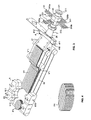
- the two veins V'1 and V "1 leaving the dispensing orifices 24a and 24b are each formed of superimposed layers of continuous lamellae.
- the lower vein V ' is deposited on the upper strand of a main conveyor belt 51, while the second vein is received on the upper run of a secondary conveyor belt 52, disposed above the main conveyor belt 51, parallel to the latter, the two bands being driven substantially in isovitesse.
- a packing dispenser (not shown) is disposed downstream of the dispensing line for depositing packing at regular intervals on the bottom vein V'1, in the form of relatively liquid coating doses, or in the form of slices G as shown in the figures.
- the filling distributor is for example of the type described in the document EP Patent 1 509 089 and comprises a notched wheel for conveying the liner laterally between the two conveyor belts 51 and 52.
- the secondary conveyor belt 52 is of shorter length than that of the main conveyor belt 51, and the upper vein V "1 is deposited at the outlet of this secondary conveyor belt 52 on the lower vein V'1 and the trim strips G which have just been deposited, to form the main continuous vein of laminated and filled meat V1.
- the main vein is transferred as it is formed to a cutting and forming device 6, shown partially and schematically in the figures, operating in synchronism with the main conveyor belt 51, firstly to treat the vein V1 as of its formation, and secondly make portioning cuts substantially in the middle of the intervals between the successive packing slices.
- the cutting and forming device 6 is of the type described in the patent documents EP 1 397 047 and EP 1 509 089 above, comprising a conveyor belt called forming conveyor belt, intended to advance the main vein V1 as its formation, which is in practice advantageously confused with the main conveyor belt 51 on which is constituted the main vein V1.
- the device comprises along the latter, downstream of the secondary conveyor belt 52, means for cutting said vein into portions, lateral forming means acting simultaneously on each side of said vein to form the contour of said portions, and vertical forming means cooperating with said lateral forming means to give said portions the desired thickness.
- the lateral forming means associated with the band 52 comprise notched lateral forming blocks 61 which slide symmetrically on each side and immediately above it.
- the blocks are mounted adjacent one after the other in the same endless loop arrangement mounted above the band 52. From upstream to downstream on the strip, the blocks 7 are gradually approaching each other. , until touching to form with it, by their indentations 611, forming cells, and then they move away again. Said lateral forming blocks each have two indentations on each side of a central point 612, so that the forming cells each form between two consecutive pairs of lateral forming blocks facing each other. Only two consecutive pairs of forming blocks are illustrated in the figures.
- the blocks comprise in their lower wall slots 613 by which they are slidably mounted on transverse rails which form the cutting means.
- a synchronism is provided between the filling distributor D and the running of the slides 42, so that the sectioning of the vein V takes place well in the gap between two strips of packing.
- the vertical forming means consist of pressing elements which cooperate with the lateral forming blocks to close upper said cells when they are formed, then go down in two stages therein, first to perform the compaction desired portions, then to transfer them positively to a lower level on a conveyor belt following the band 52, and ensuring their loading in packaging trays.
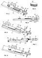
- the figure 4 very schematically represents a final product obtained P1 with a device similar to that described with reference to Figures 1 to 3 but comprising a first set of 7 horizontal oscillating blades and a second set of 5 vertical oscillating blades.
- the final product has a fibrous structure in superposed layers of strips arranged longitudinally.
- the representation of the figure 4 is of course very schematic, the strips being in contact with each other and are formed from one or more pieces of meat. In comparison to a classic ground beef, the final product retains the fibrous texture of the original cuts of meat.
- the Figures 5 and 6 illustrate an alternative embodiment of the device illustrated in Figures 1 to 3 for the manufacture of a final product P2 which differs from the product P1 in that it does not include packing.
- the distribution duct 102 comprises an inlet orifice 121 and a single orifice 122 to form a single vein V2.
- the internal main passage 123 is not subdivided into two secondary passages, it comprises as before a cutting portion 231, formed by a first piece 25, at which are mounted the two sets of oscillating blades 31 and 32, and a forming portion of which the first part 232a is formed as previously by the second piece 26 and the second part 232b is constituted this time of a piece 128 of constant rectangular cross section forming a single dispensing spout with a single orifice of 122.
- the device comprises a single main conveyor belt 51 for receiving the vein V2, and along which is positioned the cutting and forming device 6.
- the Figures 7 and 8 illustrate an alternative embodiment of the device illustrated in Figures 1 to 3 for the manufacture of a final product P3 multilayer with packing.
- the distribution pipe 202 differs from that of the Figures 1 to 3 in that it is equipped with a first cutting system comprising only a first set 31 of horizontal oscillating blades, so as to output a vein V3 of meat in superposed layers filled, from a lower vein V '3 and a vein of meat superior V ".3 Following the figure 9 the resulting textured product P3 is formed of a superposition of layers of meat.
- the figure 10 illustrates another variant which differs from that of Figures 5 and 6 in that the distribution pipe 302 is equipped with a cutting system 3 which does not comprise a set of vertical oscillating blades, the final products P4 obtained from the vein V4 being of multilayer type, such as the product P3 but without trim.
- the distribution pipe is formed of the aforementioned piece 26, which is connected directly to the pump, and the system with two beaks distribution, formed by the parts 27 and 28 above, equipped with the second cutting system 4.
- the oscillating blade then serves to cut in two layers the meat delivered by the pump, the two layers being separated to pass each in a secondary passage.
- this device can be used to form portions of turkey escalope or chicken, stuffed with a filling, whole scallops being loaded directly into the hopper feeding the pump.
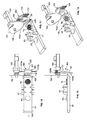
- FIGS. 11 to 13 illustrate a second embodiment in which the distribution line 402 is formed of a tubular piece 29 mounted directly at the outlet of the piston pump (not shown) and comprising a main internal passage 423 of constant inner cross section corresponding to the section of the outlet of the pump, with an inlet 421 and a dispensing orifice 422.
- the pipe is equipped with a cutting system 103 formed of a first set 131 of horizontal oscillating blades 1310a, 1310b and a second set 132 of vertical oscillating blades 1320a, 1320b disposed downstream of the first set for cutting the meat into strips or rectangular or square strips, arranged in superposed layers.
- These two sets 131, 132 are similar to those 31, 32 described above, with first blades and second blades displaced in opposite parallel back and forth movements.
- Each set 131, 132 comprises for example 13 blades.
- the forming and cutting device 106 comprises, as cutting means, a rotary knife 162 having a flat blade with a curvilinear cutting edge 162a, which is disposed perpendicular to the longitudinal axis of the pipe and parallel to the face frontal 428 of the pipe which serves as cutting marble.
- the blade is rotated by a motor 163 about an axis parallel to the axis of the pipe so as to move the curvilinear cutting edge 162a of the blade in front of the outlet orifice 422, to vertically cut into a slice T5 the meat coming out of the distribution line.
- the knife thus makes it possible to cut into small pieces the continuous strips formed at the output of the cutting system 103.
- the device comprises a conveyor belt 52 on the upper strand from which the T5 slices of small pieces of meat are recovered.
- the Figures 11 to 13 schematically illustrate the output tranche of driving on the conveyor belt, with pieces of meat all oriented vertically.
- the slice T5 which has just been cut and falling on the conveyor belt, present in the form of a cluster of small pieces of minced meat oriented in all directions.
- Lateral forming means 61 and vertical similar to those described above are arranged along the band 52 to form the contour of substantially circular portions P5, and to give them the desired thickness.
- the figure 14 illustrates a variant embodiment in which the distribution pipe 502 comprises only a first set of horizontal oscillating blades 131, to obtain at the outlet of the pipe meat slices T6 in strips oriented mainly transversely, and then circular portions P6 at the outlet of the forming.
Landscapes
- Life Sciences & Earth Sciences (AREA)
- Engineering & Computer Science (AREA)
- Wood Science & Technology (AREA)
- Zoology (AREA)
- Food Science & Technology (AREA)
- Meat, Egg Or Seafood Products (AREA)
Claims (17)
- Vorrichtung zur Herstellung von Teilen von Lebensmittelprodukten in Stücken, insbesondere von Steaks von frischem Muskelfleisch, umfassend- mindestens eine Pumpe, die geeignet ist, am Ausgang eine im Wesentlichen konstante Menge eines Lebensmittelproduktes in Stücken zu liefern,- eine röhrenförmige Verteilungsleitung, die an den Förderausgang der Pumpe angeschlossen ist, um in ihrem inneren Hauptdurchgang das aus der Pumpe kommende Lebensmittelprodukt aufzunehmen, und umfassend mindestens eine Verteilungsöffnung, und- Schneid- und Formungsmittel, die auf das von der Ausgabeöffnung der Verteilungsleitung verteilte Produkt einwirken, um Teile von Lebensmittelprodukten zu bilden,dadurch gekennzeichnet, dass die Verteilungsleitung (2, 102, 202, 302, 402, 502) mit einem Schneidsystem (3, 103, 4) ausgestattet ist, umfassend mindestens ein Schneidmittel (310a, 310b, 320a, 320b, 410, 1310a, 1310b, 1320a, 1320b), das quer durch den inneren Hauptdurchgang (23, 123, 423) der Verteilungsleitung hindurchgeht, um das Lebensmittelprodukt in mindestens zwei Schichten zu schneiden, um texturierte Teile (P1, P2, P3, P4, P5, P6) eines Lebensmittelproduktes am Ausgang der Schneid- und Formungsmittel (6, 106) zu erhalten.
- Vorrichtung nach Anspruch 1, dadurch gekennzeichnet, dass das Schneidsystem (3, 103) eine erste Einheit (31, 131) von Schneidmitteln (310a, 310b, 1310a, 1310b) umfasst, die parallel übereinander angeordnet sind, um das von der Pumpe kommende Lebensmittelprodukt in mehrere Schichten zu schneiden.
- Vorrichtung nach Anspruch 2, dadurch gekennzeichnet, dass das Schneidsystem (3, 103) eine zweite Einheit (32, 132) von Schneidmitteln (320a, 320b, 1320a, 1320b) umfasst, die parallel übereinander stromabwärts zu der ersten Einheit (31, 131) von Schneidmitteln angeordnet sind, um jede der von der ersten Einheit von Schneidmitteln kommenden Schichten in Streifen zu schneiden.
- Vorrichtung nach einem der Ansprüche 1 bis 3, dadurch gekennzeichnet, dass jedes Schneidmittel des Schneidsystems eine flache oszillierende Schneidklinge (310a, 310b, 320a, 320b, 410, 1310a, 1310b, 1320a, 1320b) umfasst.
- Vorrichtung nach Anspruch 4 in Kombination mit Anspruch 2 oder 3, dadurch gekennzeichnet, dass jede Einheit (31, 131, 32, 132) von Schneidklingen erste oszillierende Schneidklingen (310a, 320a, 1310a, 1320a), die geeignet sind, von einem ersten Verschiebesystem in einer Hin- und Herbewegung verschoben zu werden, und zweite oszillierende Schneidklingen (310b, 320b, 1310b, 1320b) umfasst, die zwischen den ersten Schneidklingen angeordnet sind und von einem zweiten Verschiebesystem in einer zu jener der ersten oszillierenden Schneidklingen entgegengesetzten Hin- und Herbewegung verschoben werden.
- Vorrichtung nach einem der Ansprüche 1 bis 5, dadurch gekennzeichnet, dass die Schneid- und Formungsmittel (6) ein Formungsförderband (51), um einen Lebensmittelproduktstrom, der von der Verteilungsleitung kommt, aufzunehmen, und entlang desselben Mittel zum Schneiden des Stroms in Teile umfassen, wobei seitliche Formungsmittel (61) gleichzeitig auf jeder Seite des Stroms einwirken, um die Kontur der Teile zu bilden, und wobei vertikale Formungsmittel mit den seitlichen Formungsmitteln zusammenwirken, um den Teilen die gewünschte Dicke zu verleihen.
- Vorrichtung nach einem der Ansprüche 1 bis 6, dadurch gekennzeichnet, dass die Verteilungsleitung (2, 202) mit einem Schneidsystem ausgestattet ist, umfassend ein Schneidmittel (410), das stromaufwärts zu Trennmitteln (27, 28) angeordnet ist, um den inneren Hauptdurchgang (23) von der Verteilungsleitung in zwei Nebendurchgänge (24a, 24b) zu trennen, um einen oberen Lebensmittelproduktstrom (V''1, V''3) und einen unteren Lebensmittelproduktstrom (V'1, V''3) zu bilden, wobei die Vorrichtung ein Hauptförderband (51), um den unteren Lebensmittelproduktstrom aufzunehmen, ein kontinuierlich ablaufendes Nebenförderband (52), das über dem Hauptförderband angeordnet ist, um den oberen Strom aufzunehmen, und Mittel zum Auftragen einer Füllung umfasst, die geeignet sind, eine Füllung auf den unteren Strom aufzutragen, wobei das Nebenförderband geeignet ist, den oberen Strom auf den unteren Strom und die Füllung zu befördern und aufzubringen.
- Vorrichtung nach einem der Ansprüche 1 bis 5, dadurch gekennzeichnet, dass die Schneid- und Formungsmittel ein Messer (162), das geeignet ist, das aus der Verteilungsleitung (402, 502) kommende Lebensmittelprodukt durchzuschneiden, ein Förderband (51), um die Scheiben (T5, T6), die von dem Messer gebildet werden, aufzunehmen, und entlang dieses Förderbandes seitliche Formungsmittel (61), um die Kontur der Teile zu bilden, und vertikale Formungsmittel umfassen, um den Teilen die gewünschte Dicke zu verleihen.
- Vorrichtung nach einem der Ansprüche 1 bis 8, dadurch gekennzeichnet, dass die Pumpe (1) eine Pumpe vom Typ Rotationskolbenpumpe ist, umfassend einen Stator (12), der einen zylindrischen Hohlraum definiert, einen Rotor oder eine Trommel (13), die in dem zylindrischen Hohlraum angeordnet und geeignet sind, von einem Motor in Drehung angetrieben zu werden, wobei der Rotor eine Gesamtheit von in Umfangsrichtung beabstandeten Bohrungen (14) umfasst, in denen Kolben (15) montiert sind, eine mechanische Nocke, die mit den Kolben zusammenwirkt, um bei der Drehung der Trommel eine alternierende Hin- und Herbewegung der Kolben zwischen einer unteren Position und einer oberen Position hervorzurufen, einen Deckel, der den zylindrischen Hohlraum verschließt, eine Versorgungsöffnung, die mit mindestens einer zylindrischen Kammer, die von einer zylindrischen Bohrung der Trommel und ihrem zugehörigen Kolben gebildet ist, in Verbindung kommt und dazu bestimmt ist, mit einem Trichter verbunden zu sein, eine Förderöffnung, die geeignet ist, gleichzeitig mit mindestens zwei aufeinanderfolgenden zylindrischen Kammern in Verbindung zu stehen.
- Vorrichtung nach Anspruch 9, dadurch gekennzeichnet, dass die Pumpe ferner Mittel zum Setzen der zylindrischen Kammern unter Vakuum zu ihrer Füllung, wobei die Mittel zur Herstellung eines Vakuums mindestens einen Kanal zur Herstellung eines Vakuums umfassen, der in den unteren Teil jeder zylindrischen Kammer mündet, wobei die Mittel zur Herstellung eines Vakuums geeignet sind, jede zylindrische Kammer von unten über ihren Kanal zur Herstellung eines Vakuums unter Vakuum zu setzen, wenn sich ihr zugehöriger Kolben in der unteren Position befindet.
- Vorrichtung nach Anspruch 9 oder 10, dadurch gekennzeichnet, dass die Pumpe ferner Schneidmittel umfasst, die eine Schneidklinge aufweisen, die entlang des stromabwärtigen Randes der Versorgungsöffnung angeordnet ist, um die Produktstücke, die von den zylindrischen Kammern bei ihrem Durchgang über die Versorgungsöffnung hinausragen, abzuschneiden.
- Verfahren zur Herstellung von Teilen von Lebensmittelprodukten in Stücken, insbesondere von Steaks von frischem Muskelfleisch, dadurch gekennzeichnet, dass es umfasst:a) einen Schritt der Bildung eines im Wesentlichen konstanten Stroms eines Lebensmittelproduktes in Stücken in einer Verteilungsleitung (2, 102, 202, 302, 402, 502),b) einen Schritt des Schneidens des Lebensmittelproduktes in der Verteilungsleitung in mindestens zwei Schichten, undc) einen Schritt des Schneidens und Formens des Lebensmittelprodukts am Ausgang einer Verteilungsleitung, um Teile (P1-P6) von Lebensmittelprodukten zu bilden, die die Textur des Ausgangslebensmittelproduktes haben.
- Verfahren nach Anspruch 12, dadurch gekennzeichnet, dass in Schritt a) das Lebensmittelprodukt in eine Vielzahl von übereinander liegenden durchgehenden horizontalen Schichten geschnitten wird.
- Verfahren nach Anspruch 13, dadurch gekennzeichnet, dass in Schritt a) jede horizontale Schicht eines Lebensmittelprodukts in eine Vielzahl von durchgehenden Streifen geschnitten wird.
- Verfahren nach Anspruch 13 oder 14, dadurch gekennzeichnet, dass das Lebensmittelprodukt am Ausgang der Verteilungsleitung (2, 102, 202, 302) in Form mindestens eines kontinuierlichen Stroms (V1-V4) vorhanden ist, wobei Schritt c) das Schneiden und Formen des Stroms in Teile eines Lebensmittelprodukts in übereinander liegenden Schichten (P3, P4) oder in Längsstreifen (P1, P2) umfasst.
- Verfahren nach einem der Ansprüche 12 bis 15, dadurch gekennzeichnet, dass das Lebensmittelprodukt am Ausgang der Verteilungsleitung (2, 202) in Form eines unteren kontinuierlichen Stroms (V'1, V'3) und eines oberen kontinuierlichen Stroms (V''1, V''3), der den unteren Strom überdeckt, vorhanden ist, wobei das Verfahren ferner einen Schritt umfasst, darin bestehend, eine Füllung (G) auf den unteren Strom vor seiner Überdeckung durch den oberen Strom aufzutragen, um einen gefüllten kontinuierlichen Hauptstrom (V1, V3) zu bilden, wobei Schritt c) das Schneiden und Formen des Hauptstroms in mit einer Füllung gefüllte Teile von Lebensmittelprodukten (P1, P3) umfasst.
- Verfahren nach einem der Ansprüche 13 oder 14, dadurch gekennzeichnet, dass in Schritt c) das Lebensmittelprodukt am Ausgang einer Verteilungsleitung (402, 502) in Scheiben (T5, T6) geschnitten wird, um nach der Formung Teile eines Lebensmittelprodukts in Querstreifen oder in kleinen Stücken eines Lebensmittelprodukts zu bilden.
Applications Claiming Priority (2)
| Application Number | Priority Date | Filing Date | Title |
|---|---|---|---|
| FR0703109A FR2915348B1 (fr) | 2007-04-27 | 2007-04-27 | Dispositif de fabrication de portions de produits alimentaires texturees |
| PCT/FR2008/000587 WO2008145860A1 (fr) | 2007-04-27 | 2008-04-24 | Dispositif de fabrication de portions de produits alimentaires texturees |
Publications (2)
| Publication Number | Publication Date |
|---|---|
| EP2139343A1 EP2139343A1 (de) | 2010-01-06 |
| EP2139343B1 true EP2139343B1 (de) | 2016-01-13 |
Family
ID=38870335
Family Applications (1)
| Application Number | Title | Priority Date | Filing Date |
|---|---|---|---|
| EP08805505.8A Not-in-force EP2139343B1 (de) | 2007-04-27 | 2008-04-24 | Vorrichtung zur herstellung texturierter teile von lebensmittelprodukten |
Country Status (8)
| Country | Link |
|---|---|
| US (2) | US8376728B2 (de) |
| EP (1) | EP2139343B1 (de) |
| JP (1) | JP2010524487A (de) |
| BR (1) | BRPI0810588A2 (de) |
| DK (1) | DK2139343T3 (de) |
| ES (1) | ES2565540T3 (de) |
| FR (1) | FR2915348B1 (de) |
| WO (1) | WO2008145860A1 (de) |
Families Citing this family (10)
| Publication number | Priority date | Publication date | Assignee | Title |
|---|---|---|---|---|
| PL2281468T3 (pl) * | 2009-08-03 | 2012-06-29 | Kraft Foods R & D Inc | Sposób przetwarzania materiału spożywczego z zastosowaniem impulsowej wiązki laserowej |
| US9772999B2 (en) * | 2011-10-24 | 2017-09-26 | Imagescan, Inc. | Apparatus and method for displaying multiple display panels with a progressive relationship using cognitive pattern recognition |
| US8800813B1 (en) | 2011-11-15 | 2014-08-12 | Hormel Foods Corporation | Metering product delivery pump system |
| DE102015103423B4 (de) * | 2015-03-09 | 2017-11-30 | Vemag Maschinenbau Gmbh | System zum Formen und Fördern von Lebensmittelprodukten aus pastöser Masse |
| CN105053143B (zh) * | 2015-08-06 | 2017-05-10 | 青岛振坤食品机械有限公司 | 一种自动切穿机 |
| CN107813648A (zh) * | 2016-09-13 | 2018-03-20 | 廖竞光 | 一种全自动马赛克铺贴纸生产设备 |
| CN115003165A (zh) * | 2020-01-27 | 2022-09-02 | 日本水产株式会社 | 一种面条形状体集合体及其制造方法 |
| JP6929411B2 (ja) * | 2020-01-27 | 2021-09-01 | 日本水産株式会社 | 麺状体集合体の製造方法 |
| DE102020204024B3 (de) * | 2020-03-27 | 2021-01-07 | Albert Handtmann Maschinenfabrik Gmbh & Co. Kg | Baugruppe und anlage zur herstellung pastöser formteile |
| WO2025125494A1 (en) * | 2023-12-14 | 2025-06-19 | Gea Food Solutions Bakel B.V. | A production line for producing individual food products and a method for producing individual food products |
Family Cites Families (28)
| Publication number | Priority date | Publication date | Assignee | Title |
|---|---|---|---|---|
| US1783096A (en) * | 1928-10-31 | 1930-11-25 | William J Pearce | Butter-cutting machine |
| US2916986A (en) * | 1954-06-04 | 1959-12-15 | Lebo Press Co | Machine for stripping frozen fish |
| DE1247572B (de) * | 1966-03-23 | 1967-08-17 | Ernst Holz | Wuerfelschneideinrichtung fuer Speck und andere Lebensmittel |
| US3789750A (en) * | 1969-04-16 | 1974-02-05 | R Beck | Apparatus for reconstituting dry potato agglomerates into potato dough |
| US3956518A (en) * | 1972-06-06 | 1976-05-11 | Kraftco Corporation | Method of slicing and stacking cheese |
| US4068008A (en) * | 1974-01-28 | 1978-01-10 | Rca Corporation | Food product extrusion apparatus and method |
| US4205415A (en) * | 1974-01-28 | 1980-06-03 | Rca Corporation | Food product extrusion apparatus |
| US4382970A (en) * | 1980-02-26 | 1983-05-10 | Getfresh Food Limited | Food processing |
| US4797291A (en) * | 1985-07-01 | 1989-01-10 | William W. Pierce | Method of preparing a comestible with insert |
| DE3544807C2 (de) * | 1985-12-18 | 1995-08-10 | Holac Maschbau Gmbh | Vorrichtung zum Schneiden von Lebensmitteln |
| US4768941A (en) * | 1986-06-16 | 1988-09-06 | Hollymatic Corporation | Food patty and machine and method for making thereof |
| JPS63207612A (ja) * | 1987-02-24 | 1988-08-29 | 日本碍子株式会社 | セラミツク押出法及びそれに用いる装置 |
| US4988276A (en) * | 1988-08-01 | 1991-01-29 | Nabisco Brands, Inc. | Apparatus for shaping cookie dough |
| US5104667A (en) * | 1988-08-01 | 1992-04-14 | Nabisco Brands, Inc. | Process of making coarse cookies |
| US5514397A (en) * | 1992-04-02 | 1996-05-07 | Holy Ravioli Pasta Company | Process for making a layered dough sheet product |
| US5356652A (en) * | 1992-08-19 | 1994-10-18 | Campbell Sterrett P | Method of distributing baker's dough |
| US5264232A (en) * | 1992-08-19 | 1993-11-23 | Campbell Sterrett P | Method of dividing a single stream of baker's dough into separate streams of equal weight |
| GB2294380B (en) * | 1994-10-29 | 1997-07-09 | Brian Hogan | A food manufacturing system |
| US5765768A (en) * | 1996-03-06 | 1998-06-16 | Visionary Design, Inc. | Plate for use on the outlet of a food grinder for making sheets of food |
| US20040265456A1 (en) * | 1997-11-14 | 2004-12-30 | Ward Halverson | Product preparation system with extrusion horn |
| IT1299031B1 (it) * | 1998-04-06 | 2000-02-07 | Antonio Bei | Pressa per il trattamento ed il recupero di rifiuti solidi urbani ed assimilabili preselezionati |
| IT1305285B1 (it) * | 1999-01-18 | 2001-05-04 | Refin Srl | Dispositivo per porzionare carne macinata per il confezionamento invaschetta o simile. |
| BRPI0009757B1 (pt) * | 1999-04-13 | 2015-06-02 | Ole-Bendt Rasmussen | Produto alimentício tridimensional |
| FR2826237B1 (fr) * | 2001-06-22 | 2003-12-12 | Nijal | Dispositifs de formage de portions de viande hachee tels que steaks, boulettes, etc |
| FR2840159B1 (fr) * | 2002-05-29 | 2004-07-23 | Nijal | Procede et dispositifs de fabrication de steaks haches fourres d'une garniture |
| US6932998B2 (en) * | 2003-06-05 | 2005-08-23 | Formax, Inc. | Apparatus and method for forming two component food product |
| FR2884287B1 (fr) * | 2005-04-11 | 2007-05-18 | Nijal Soc Par Actions Simplifi | Pompe rotative a pistons |
| US20080160128A1 (en) * | 2006-12-29 | 2008-07-03 | Aac Trade Ltd. | Food processor implement |
-
2007
- 2007-04-27 FR FR0703109A patent/FR2915348B1/fr not_active Expired - Fee Related
-
2008
- 2008-04-24 EP EP08805505.8A patent/EP2139343B1/de not_active Not-in-force
- 2008-04-24 DK DK08805505.8T patent/DK2139343T3/en active
- 2008-04-24 BR BRPI0810588-0A patent/BRPI0810588A2/pt not_active Application Discontinuation
- 2008-04-24 ES ES08805505.8T patent/ES2565540T3/es active Active
- 2008-04-24 WO PCT/FR2008/000587 patent/WO2008145860A1/fr not_active Ceased
- 2008-04-24 US US12/597,428 patent/US8376728B2/en not_active Expired - Fee Related
- 2008-04-24 JP JP2010504787A patent/JP2010524487A/ja active Pending
-
2013
- 2013-01-18 US US13/745,214 patent/US20130129851A1/en not_active Abandoned
Also Published As
| Publication number | Publication date |
|---|---|
| WO2008145860A1 (fr) | 2008-12-04 |
| JP2010524487A (ja) | 2010-07-22 |
| EP2139343A1 (de) | 2010-01-06 |
| ES2565540T3 (es) | 2016-04-05 |
| FR2915348B1 (fr) | 2009-07-10 |
| FR2915348A1 (fr) | 2008-10-31 |
| DK2139343T3 (en) | 2016-03-29 |
| US20130129851A1 (en) | 2013-05-23 |
| US20100129513A1 (en) | 2010-05-27 |
| BRPI0810588A2 (pt) | 2014-09-16 |
| US8376728B2 (en) | 2013-02-19 |
Similar Documents
| Publication | Publication Date | Title |
|---|---|---|
| EP2139343B1 (de) | Vorrichtung zur herstellung texturierter teile von lebensmittelprodukten | |
| EP1524907B1 (de) | Beschichtetes nahrungsmittel, zusammensetzung, verfahren und vorrichtung zur herstellung davon | |
| EP0362099B1 (de) | Vorrichtung zum kontinuierlichen Herstellen von im wesentlichen würfelförmigen Fleischstücken | |
| EP1397047A1 (de) | Vorrichtungen zur herstellung von hackfleischportionen wie steaks, klössen usw | |
| EP2438818B1 (de) | Verfahren und Vorrichtung zum Herstellen von Portionen von Lebensmittelprodukten, die mit einer Garnierung versehen sind. | |
| EP1509089B1 (de) | Verfahren und vorrichtung zur herstellung von hackfleisch mit einer füllung | |
| EP2038065B1 (de) | Lochscheibe für einen fleischwolf | |
| EP1973410B1 (de) | Verfahren zur mengenteilung von teig | |
| EP2364594B1 (de) | Teigportionierverfahren | |
| EP1869320B1 (de) | Rotationskolbenpumpe | |
| EP4327994A1 (de) | Verfahren zur herstellung von verpackungszuschnitten und entsprechendes modul | |
| EP1935590A1 (de) | Schnittvorrichtung für Lebensmittelprodukte mit mehreren Schnittmitteln | |
| FR2902292A1 (fr) | Procede de division volumetrique de pate et son dispositif de mise en oeuvre | |
| FR2826236A1 (fr) | Dispositifs de formage de steaks haches | |
| EP4652845A1 (de) | Vorrichtung zum formen von teigwaren, anlage und verfahren zu deren herstellung | |
| FR3032690A1 (fr) | Dispositif et methode de mise en conserve de poissons | |
| EP3714696A2 (de) | Anlage für die herstellung von macaronschalen | |
| WO2011045480A1 (fr) | Procede et dispositif pour la fabrication de produit alimentaire a plusieurs composants | |
| FR2883454A1 (fr) | Chair congelee en morceaux, conditionnement de celle-ci et son procede de preparation |
Legal Events
| Date | Code | Title | Description |
|---|---|---|---|
| PUAI | Public reference made under article 153(3) epc to a published international application that has entered the european phase |
Free format text: ORIGINAL CODE: 0009012 |
|
| 17P | Request for examination filed |
Effective date: 20091026 |
|
| AK | Designated contracting states |
Kind code of ref document: A1 Designated state(s): AT BE BG CH CY CZ DE DK EE ES FI FR GB GR HR HU IE IS IT LI LT LU LV MC MT NL NO PL PT RO SE SI SK TR |
|
| DAX | Request for extension of the european patent (deleted) | ||
| RAP1 | Party data changed (applicant data changed or rights of an application transferred) |
Owner name: MAREL FRANCE |
|
| GRAP | Despatch of communication of intention to grant a patent |
Free format text: ORIGINAL CODE: EPIDOSNIGR1 |
|
| INTG | Intention to grant announced |
Effective date: 20150722 |
|
| GRAS | Grant fee paid |
Free format text: ORIGINAL CODE: EPIDOSNIGR3 |
|
| GRAA | (expected) grant |
Free format text: ORIGINAL CODE: 0009210 |
|
| AK | Designated contracting states |
Kind code of ref document: B1 Designated state(s): AT BE BG CH CY CZ DE DK EE ES FI FR GB GR HR HU IE IS IT LI LT LU LV MC MT NL NO PL PT RO SE SI SK TR |
|
| REG | Reference to a national code |
Ref country code: GB Ref legal event code: FG4D Free format text: NOT ENGLISH |
|
| REG | Reference to a national code |
Ref country code: CH Ref legal event code: EP |
|
| REG | Reference to a national code |
Ref country code: IE Ref legal event code: FG4D Free format text: LANGUAGE OF EP DOCUMENT: FRENCH |
|
| REG | Reference to a national code |
Ref country code: AT Ref legal event code: REF Ref document number: 769871 Country of ref document: AT Kind code of ref document: T Effective date: 20160215 |
|
| REG | Reference to a national code |
Ref country code: DE Ref legal event code: R096 Ref document number: 602008042057 Country of ref document: DE |
|
| REG | Reference to a national code |
Ref country code: FR Ref legal event code: PLFP Year of fee payment: 9 |
|
| REG | Reference to a national code |
Ref country code: DK Ref legal event code: T3 Effective date: 20160322 |
|
| REG | Reference to a national code |
Ref country code: ES Ref legal event code: FG2A Ref document number: 2565540 Country of ref document: ES Kind code of ref document: T3 Effective date: 20160405 |
|
| REG | Reference to a national code |
Ref country code: SE Ref legal event code: TRGR |
|
| REG | Reference to a national code |
Ref country code: NL Ref legal event code: FP |
|
| REG | Reference to a national code |
Ref country code: LT Ref legal event code: MG4D |
|
| REG | Reference to a national code |
Ref country code: AT Ref legal event code: MK05 Ref document number: 769871 Country of ref document: AT Kind code of ref document: T Effective date: 20160113 |
|
| PG25 | Lapsed in a contracting state [announced via postgrant information from national office to epo] |
Ref country code: HR Free format text: LAPSE BECAUSE OF FAILURE TO SUBMIT A TRANSLATION OF THE DESCRIPTION OR TO PAY THE FEE WITHIN THE PRESCRIBED TIME-LIMIT Effective date: 20160113 Ref country code: FI Free format text: LAPSE BECAUSE OF FAILURE TO SUBMIT A TRANSLATION OF THE DESCRIPTION OR TO PAY THE FEE WITHIN THE PRESCRIBED TIME-LIMIT Effective date: 20160113 Ref country code: GR Free format text: LAPSE BECAUSE OF FAILURE TO SUBMIT A TRANSLATION OF THE DESCRIPTION OR TO PAY THE FEE WITHIN THE PRESCRIBED TIME-LIMIT Effective date: 20160414 Ref country code: NO Free format text: LAPSE BECAUSE OF FAILURE TO SUBMIT A TRANSLATION OF THE DESCRIPTION OR TO PAY THE FEE WITHIN THE PRESCRIBED TIME-LIMIT Effective date: 20160413 |
|
| PG25 | Lapsed in a contracting state [announced via postgrant information from national office to epo] |
Ref country code: BE Free format text: LAPSE BECAUSE OF NON-PAYMENT OF DUE FEES Effective date: 20160430 Ref country code: LV Free format text: LAPSE BECAUSE OF FAILURE TO SUBMIT A TRANSLATION OF THE DESCRIPTION OR TO PAY THE FEE WITHIN THE PRESCRIBED TIME-LIMIT Effective date: 20160113 Ref country code: LT Free format text: LAPSE BECAUSE OF FAILURE TO SUBMIT A TRANSLATION OF THE DESCRIPTION OR TO PAY THE FEE WITHIN THE PRESCRIBED TIME-LIMIT Effective date: 20160113 Ref country code: IS Free format text: LAPSE BECAUSE OF FAILURE TO SUBMIT A TRANSLATION OF THE DESCRIPTION OR TO PAY THE FEE WITHIN THE PRESCRIBED TIME-LIMIT Effective date: 20160513 Ref country code: AT Free format text: LAPSE BECAUSE OF FAILURE TO SUBMIT A TRANSLATION OF THE DESCRIPTION OR TO PAY THE FEE WITHIN THE PRESCRIBED TIME-LIMIT Effective date: 20160113 Ref country code: PT Free format text: LAPSE BECAUSE OF FAILURE TO SUBMIT A TRANSLATION OF THE DESCRIPTION OR TO PAY THE FEE WITHIN THE PRESCRIBED TIME-LIMIT Effective date: 20160513 Ref country code: PL Free format text: LAPSE BECAUSE OF FAILURE TO SUBMIT A TRANSLATION OF THE DESCRIPTION OR TO PAY THE FEE WITHIN THE PRESCRIBED TIME-LIMIT Effective date: 20160113 |
|
| REG | Reference to a national code |
Ref country code: DE Ref legal event code: R097 Ref document number: 602008042057 Country of ref document: DE |
|
| PG25 | Lapsed in a contracting state [announced via postgrant information from national office to epo] |
Ref country code: EE Free format text: LAPSE BECAUSE OF FAILURE TO SUBMIT A TRANSLATION OF THE DESCRIPTION OR TO PAY THE FEE WITHIN THE PRESCRIBED TIME-LIMIT Effective date: 20160113 |
|
| PLBE | No opposition filed within time limit |
Free format text: ORIGINAL CODE: 0009261 |
|
| STAA | Information on the status of an ep patent application or granted ep patent |
Free format text: STATUS: NO OPPOSITION FILED WITHIN TIME LIMIT |
|
| PG25 | Lapsed in a contracting state [announced via postgrant information from national office to epo] |
Ref country code: SK Free format text: LAPSE BECAUSE OF FAILURE TO SUBMIT A TRANSLATION OF THE DESCRIPTION OR TO PAY THE FEE WITHIN THE PRESCRIBED TIME-LIMIT Effective date: 20160113 Ref country code: CZ Free format text: LAPSE BECAUSE OF FAILURE TO SUBMIT A TRANSLATION OF THE DESCRIPTION OR TO PAY THE FEE WITHIN THE PRESCRIBED TIME-LIMIT Effective date: 20160113 Ref country code: RO Free format text: LAPSE BECAUSE OF FAILURE TO SUBMIT A TRANSLATION OF THE DESCRIPTION OR TO PAY THE FEE WITHIN THE PRESCRIBED TIME-LIMIT Effective date: 20160113 |
|
| REG | Reference to a national code |
Ref country code: CH Ref legal event code: PL |
|
| 26N | No opposition filed |
Effective date: 20161014 |
|
| PG25 | Lapsed in a contracting state [announced via postgrant information from national office to epo] |
Ref country code: LU Free format text: LAPSE BECAUSE OF FAILURE TO SUBMIT A TRANSLATION OF THE DESCRIPTION OR TO PAY THE FEE WITHIN THE PRESCRIBED TIME-LIMIT Effective date: 20160424 |
|
| REG | Reference to a national code |
Ref country code: IE Ref legal event code: MM4A |
|
| PG25 | Lapsed in a contracting state [announced via postgrant information from national office to epo] |
Ref country code: LI Free format text: LAPSE BECAUSE OF NON-PAYMENT OF DUE FEES Effective date: 20160430 Ref country code: CH Free format text: LAPSE BECAUSE OF NON-PAYMENT OF DUE FEES Effective date: 20160430 |
|
| PG25 | Lapsed in a contracting state [announced via postgrant information from national office to epo] |
Ref country code: SI Free format text: LAPSE BECAUSE OF FAILURE TO SUBMIT A TRANSLATION OF THE DESCRIPTION OR TO PAY THE FEE WITHIN THE PRESCRIBED TIME-LIMIT Effective date: 20160113 Ref country code: BG Free format text: LAPSE BECAUSE OF FAILURE TO SUBMIT A TRANSLATION OF THE DESCRIPTION OR TO PAY THE FEE WITHIN THE PRESCRIBED TIME-LIMIT Effective date: 20160413 |
|
| REG | Reference to a national code |
Ref country code: FR Ref legal event code: PLFP Year of fee payment: 10 |
|
| PG25 | Lapsed in a contracting state [announced via postgrant information from national office to epo] |
Ref country code: IE Free format text: LAPSE BECAUSE OF NON-PAYMENT OF DUE FEES Effective date: 20160424 |
|
| REG | Reference to a national code |
Ref country code: FR Ref legal event code: PLFP Year of fee payment: 11 |
|
| PG25 | Lapsed in a contracting state [announced via postgrant information from national office to epo] |
Ref country code: HU Free format text: LAPSE BECAUSE OF FAILURE TO SUBMIT A TRANSLATION OF THE DESCRIPTION OR TO PAY THE FEE WITHIN THE PRESCRIBED TIME-LIMIT; INVALID AB INITIO Effective date: 20080424 Ref country code: CY Free format text: LAPSE BECAUSE OF FAILURE TO SUBMIT A TRANSLATION OF THE DESCRIPTION OR TO PAY THE FEE WITHIN THE PRESCRIBED TIME-LIMIT Effective date: 20160113 |
|
| PG25 | Lapsed in a contracting state [announced via postgrant information from national office to epo] |
Ref country code: MT Free format text: LAPSE BECAUSE OF FAILURE TO SUBMIT A TRANSLATION OF THE DESCRIPTION OR TO PAY THE FEE WITHIN THE PRESCRIBED TIME-LIMIT Effective date: 20160113 Ref country code: MC Free format text: LAPSE BECAUSE OF FAILURE TO SUBMIT A TRANSLATION OF THE DESCRIPTION OR TO PAY THE FEE WITHIN THE PRESCRIBED TIME-LIMIT Effective date: 20160113 Ref country code: TR Free format text: LAPSE BECAUSE OF FAILURE TO SUBMIT A TRANSLATION OF THE DESCRIPTION OR TO PAY THE FEE WITHIN THE PRESCRIBED TIME-LIMIT Effective date: 20160113 |
|
| PGFP | Annual fee paid to national office [announced via postgrant information from national office to epo] |
Ref country code: ES Payment date: 20200504 Year of fee payment: 13 |
|
| PGFP | Annual fee paid to national office [announced via postgrant information from national office to epo] |
Ref country code: GB Payment date: 20200427 Year of fee payment: 13 Ref country code: SE Payment date: 20200429 Year of fee payment: 13 |
|
| REG | Reference to a national code |
Ref country code: SE Ref legal event code: EUG |
|
| GBPC | Gb: european patent ceased through non-payment of renewal fee |
Effective date: 20210424 |
|
| PG25 | Lapsed in a contracting state [announced via postgrant information from national office to epo] |
Ref country code: SE Free format text: LAPSE BECAUSE OF NON-PAYMENT OF DUE FEES Effective date: 20210425 Ref country code: GB Free format text: LAPSE BECAUSE OF NON-PAYMENT OF DUE FEES Effective date: 20210424 |
|
| REG | Reference to a national code |
Ref country code: ES Ref legal event code: FD2A Effective date: 20220706 |
|
| PG25 | Lapsed in a contracting state [announced via postgrant information from national office to epo] |
Ref country code: ES Free format text: LAPSE BECAUSE OF NON-PAYMENT OF DUE FEES Effective date: 20210425 |
|
| PGFP | Annual fee paid to national office [announced via postgrant information from national office to epo] |
Ref country code: FR Payment date: 20230321 Year of fee payment: 16 Ref country code: DK Payment date: 20230321 Year of fee payment: 16 |
|
| PGFP | Annual fee paid to national office [announced via postgrant information from national office to epo] |
Ref country code: IT Payment date: 20230322 Year of fee payment: 16 |
|
| P01 | Opt-out of the competence of the unified patent court (upc) registered |
Effective date: 20230514 |
|
| PGFP | Annual fee paid to national office [announced via postgrant information from national office to epo] |
Ref country code: NL Payment date: 20230321 Year of fee payment: 16 |
|
| PGFP | Annual fee paid to national office [announced via postgrant information from national office to epo] |
Ref country code: DE Payment date: 20230321 Year of fee payment: 16 |
|
| REG | Reference to a national code |
Ref country code: DE Ref legal event code: R119 Ref document number: 602008042057 Country of ref document: DE |
|
| REG | Reference to a national code |
Ref country code: DK Ref legal event code: EBP Effective date: 20240430 |
|
| REG | Reference to a national code |
Ref country code: NL Ref legal event code: MM Effective date: 20240501 |
|
| PG25 | Lapsed in a contracting state [announced via postgrant information from national office to epo] |
Ref country code: DE Free format text: LAPSE BECAUSE OF NON-PAYMENT OF DUE FEES Effective date: 20241105 |
|
| PG25 | Lapsed in a contracting state [announced via postgrant information from national office to epo] |
Ref country code: NL Free format text: LAPSE BECAUSE OF NON-PAYMENT OF DUE FEES Effective date: 20240501 |
|
| PG25 | Lapsed in a contracting state [announced via postgrant information from national office to epo] |
Ref country code: FR Free format text: LAPSE BECAUSE OF NON-PAYMENT OF DUE FEES Effective date: 20240430 |
|
| PG25 | Lapsed in a contracting state [announced via postgrant information from national office to epo] |
Ref country code: NL Free format text: LAPSE BECAUSE OF NON-PAYMENT OF DUE FEES Effective date: 20240501 Ref country code: FR Free format text: LAPSE BECAUSE OF NON-PAYMENT OF DUE FEES Effective date: 20240430 Ref country code: DE Free format text: LAPSE BECAUSE OF NON-PAYMENT OF DUE FEES Effective date: 20241105 |
|
| PG25 | Lapsed in a contracting state [announced via postgrant information from national office to epo] |
Ref country code: DK Free format text: LAPSE BECAUSE OF NON-PAYMENT OF DUE FEES Effective date: 20240430 |
|
| PG25 | Lapsed in a contracting state [announced via postgrant information from national office to epo] |
Ref country code: IT Free format text: LAPSE BECAUSE OF NON-PAYMENT OF DUE FEES Effective date: 20240424 |