EP3367501A1 - Rotierende intelligente automatische herstellungsvorrichtung für flachspulenantenne - Google Patents
Rotierende intelligente automatische herstellungsvorrichtung für flachspulenantenne Download PDFInfo
- Publication number
- EP3367501A1 EP3367501A1 EP16857635.3A EP16857635A EP3367501A1 EP 3367501 A1 EP3367501 A1 EP 3367501A1 EP 16857635 A EP16857635 A EP 16857635A EP 3367501 A1 EP3367501 A1 EP 3367501A1
- Authority
- EP
- European Patent Office
- Prior art keywords
- coil antenna
- rotary
- module
- planar
- type
- Prior art date
- Legal status (The legal status is an assumption and is not a legal conclusion. Google has not performed a legal analysis and makes no representation as to the accuracy of the status listed.)
- Withdrawn
Links
Images





Classifications
-
- H—ELECTRICITY
- H01—ELECTRIC ELEMENTS
- H01F—MAGNETS; INDUCTANCES; TRANSFORMERS; SELECTION OF MATERIALS FOR THEIR MAGNETIC PROPERTIES
- H01F41/00—Apparatus or processes specially adapted for manufacturing or assembling magnets, inductances or transformers; Apparatus or processes specially adapted for manufacturing materials characterised by their magnetic properties
- H01F41/02—Apparatus or processes specially adapted for manufacturing or assembling magnets, inductances or transformers; Apparatus or processes specially adapted for manufacturing materials characterised by their magnetic properties for manufacturing cores, coils, or magnets
- H01F41/04—Apparatus or processes specially adapted for manufacturing or assembling magnets, inductances or transformers; Apparatus or processes specially adapted for manufacturing materials characterised by their magnetic properties for manufacturing cores, coils, or magnets for manufacturing coils
- H01F41/06—Coil winding
- H01F41/071—Winding coils of special form
- H01F41/074—Winding flat coils
-
- H—ELECTRICITY
- H01—ELECTRIC ELEMENTS
- H01Q—ANTENNAS, i.e. RADIO AERIALS
- H01Q7/00—Loop antennas with a substantially uniform current distribution around the loop and having a directional radiation pattern in a plane perpendicular to the plane of the loop
-
- B—PERFORMING OPERATIONS; TRANSPORTING
- B25—HAND TOOLS; PORTABLE POWER-DRIVEN TOOLS; MANIPULATORS
- B25J—MANIPULATORS; CHAMBERS PROVIDED WITH MANIPULATION DEVICES
- B25J11/00—Manipulators not otherwise provided for
-
- G—PHYSICS
- G05—CONTROLLING; REGULATING
- G05B—CONTROL OR REGULATING SYSTEMS IN GENERAL; FUNCTIONAL ELEMENTS OF SUCH SYSTEMS; MONITORING OR TESTING ARRANGEMENTS FOR SUCH SYSTEMS OR ELEMENTS
- G05B19/00—Program-control systems
- G05B19/02—Program-control systems electric
- G05B19/04—Program control other than numerical control, i.e. in sequence controllers or logic controllers
- G05B19/05—Programmable logic controllers, e.g. simulating logic interconnections of signals according to ladder diagrams or function charts
- G05B19/054—Input/output
-
- H—ELECTRICITY
- H01—ELECTRIC ELEMENTS
- H01F—MAGNETS; INDUCTANCES; TRANSFORMERS; SELECTION OF MATERIALS FOR THEIR MAGNETIC PROPERTIES
- H01F41/00—Apparatus or processes specially adapted for manufacturing or assembling magnets, inductances or transformers; Apparatus or processes specially adapted for manufacturing materials characterised by their magnetic properties
- H01F41/02—Apparatus or processes specially adapted for manufacturing or assembling magnets, inductances or transformers; Apparatus or processes specially adapted for manufacturing materials characterised by their magnetic properties for manufacturing cores, coils, or magnets
- H01F41/04—Apparatus or processes specially adapted for manufacturing or assembling magnets, inductances or transformers; Apparatus or processes specially adapted for manufacturing materials characterised by their magnetic properties for manufacturing cores, coils, or magnets for manufacturing coils
- H01F41/06—Coil winding
- H01F41/09—Winding machines having two or more work holders or formers
-
- H—ELECTRICITY
- H01—ELECTRIC ELEMENTS
- H01Q—ANTENNAS, i.e. RADIO AERIALS
- H01Q1/00—Details of, or arrangements associated with, antennas
- H01Q1/12—Supports; Mounting means
- H01Q1/22—Supports; Mounting means by structural association with other equipment or articles
- H01Q1/24—Supports; Mounting means by structural association with other equipment or articles with receiving set
-
- B—PERFORMING OPERATIONS; TRANSPORTING
- B25—HAND TOOLS; PORTABLE POWER-DRIVEN TOOLS; MANIPULATORS
- B25J—MANIPULATORS; CHAMBERS PROVIDED WITH MANIPULATION DEVICES
- B25J11/00—Manipulators not otherwise provided for
- B25J11/005—Manipulators for mechanical processing tasks
-
- B—PERFORMING OPERATIONS; TRANSPORTING
- B25—HAND TOOLS; PORTABLE POWER-DRIVEN TOOLS; MANIPULATORS
- B25J—MANIPULATORS; CHAMBERS PROVIDED WITH MANIPULATION DEVICES
- B25J9/00—Program-controlled manipulators
- B25J9/0084—Program-controlled manipulators comprising a plurality of manipulators
-
- G—PHYSICS
- G05—CONTROLLING; REGULATING
- G05B—CONTROL OR REGULATING SYSTEMS IN GENERAL; FUNCTIONAL ELEMENTS OF SUCH SYSTEMS; MONITORING OR TESTING ARRANGEMENTS FOR SUCH SYSTEMS OR ELEMENTS
- G05B2219/00—Program-control systems
- G05B2219/10—Plc systems
- G05B2219/11—Plc I-O input output
- G05B2219/1105—I-O
Definitions
- the present invention relates to an apparatus for automatically manufacturing a planar coil antenna for use in smart devices (smartphones or smart watches), and more particularly to a rotary-type smart automatic manufacturing apparatus for a planar coil antenna, which automatically forms a planar coil antenna having a planarized surface by performing planar-coil winding, pressing, cold-pressing, transferring, air spraying, and preheating processes on a received rectangular planar wire while sequentially rotating in one place in a rotary manner.
- Recent personal mobile communication terminals provide wireless communication service so that users can exchange audio signals and data using compact terminals regardless of time and place.
- an antenna of a terminal is the most important part in determining transmission and reception characteristics.
- an antenna needs to exhibit excellent performance with low power.
- an antenna is formed by applying coils to a printed circuit board, a flexible printed circuit board, a sheet, an insulation film, a substrate, or the like, and subsequently a plurality of layers of conductive films, plating films, masks and tape are formed on the top and bottom surfaces of the antenna.
- the present invention has been made in view of the above problems, and it is an object of the present invention to provide a rotary-type smart automatic manufacturing apparatus for a planar coil antenna, which is capable of automating all processes of manufacturing a planar coil antenna, of manufacturing a high-quality planar coil antenna having an evenly planarized surface, and of achieving mass production of a planar coil antenna having a planarized surface.
- the rotary-type smart automatic manufacturing apparatus for a planar coil antenna is configured to automatically form a planar coil antenna having a planarized surface by performing planar-coil winding, pressing, cold-pressing, transferring, air spraying, and preheating processes on a received rectangular planar wire while sequentially rotating in one place in a rotary manner.
- the rotary-type smart automatic manufacturing apparatus for a planar coil antenna includes:
- the present invention has the following effects.
- the present invention is capable of automatically forming a planar coil antenna having a planarized surface by performing planar-coil winding, pressing, cold-pressing, transferring, air spraying, and preheating processes on a received rectangular planar wire while sequentially rotating in one place in a rotary manner, whereby all processes can be automated.
- a planar coil antenna having a planarized surface can be mass-produced by performing planar-coil winding, pressing, cold-pressing, transferring, air spraying, and preheating processes using a first, a second, a third, a fourth, a fifth and a sixth robot arms, which are operated under the control of a PLC control module.
- a rotary-type smart automatic manufacturing apparatus for a planar coil antenna is capable of automatically forming a planar coil antenna having a planarized surface by performing planar-coil winding, pressing, cold-pressing, transferring, air spraying, and preheating processes on a received rectangular planar wire while sequentially rotating in one place in a rotary manner.
- FIG. 1 is a constitutional view illustrating the components of a rotary-type smart automatic manufacturing apparatus 1 for a planar coil antenna according to the present invention
- FIG. 2 is a perspective view illustrating the components of the rotary-type smart automatic manufacturing apparatus 1 for a planar coil antenna according to the present invention.
- the apparatus is configured to automatically form a planar coil antenna having a planarized surface by performing planar-coil winding, pressing, cold-pressing, transferring, air spraying, and preheating processes on a received rectangular planar wire while sequentially rotating in one place in a rotary manner.
- the rotary-type smart automatic manufacturing apparatus 1 for a planar coil antenna specifically includes a main body 100, a rotary-type robot drive module 200, a hexagonal coil antenna forming module 300, a touch screen unit 400, and a PLC control module 500.
- the main body 100 is formed to have a rectangular box structure, and serves to protect various devices from external pressure and support the same.
- the rotary-type robot drive module is disposed on the left portion of the top surface of the main body
- the hexagonal coil antenna forming module is disposed around the rotary-type robot drive module
- the touch screen unit is disposed on the right portion of the top surface of the main body
- the PLC control module is disposed at one side of the main body.
- wheels are provided at the bottom surface of the main body to allow the main body to move conveniently.
- the rotary-type robot drive module 200 is located on the left portion of the top surface of the main body, is configured to sequentially rotate in a rotary manner so as to be aligned in one-to-one correspondence with the hexagonal coil antenna forming module, and serves to support the rear end of a planar coil antenna formed by the hexagonal coil antenna forming module so that the surface of the planar coil antenna is planarized.
- the rotary-type robot drive module includes a module body 210, a rotary member 220, a first robot arm 230, a second robot arm 240, a third robot arm 250, a fourth robot arm 260, a fifth robot arm 270, and a sixth robot arm 280.
- the module body 210 is formed to have a radial structure, and serves to protect various devices from external pressure and support the same.
- the first, second, third, fourth, fifth and sixth robot arms radially protrude from the module body, and the rotary member is formed at the lower end portion of the module body.
- the rotary member 220 is located at the lower end of the module body, and serves to sequentially rotate the first robot arm, the second robot arm, the third robot arm, the fourth robot arm, the fifth robot arm and the sixth robot arm of the module body so that the robot arms are aligned in one-to-one correspondence with the hexagonal coil antenna forming module.
- the rotary member includes a servo motor 221, a speed reducer 222, a main driver gear 223, and a final output gear 224.
- the servo motor 221 is disposed inside a main body of an actuator, and serves to generate rotational force (RPM).
- the servo motor is configured such that a permanent magnet is used as a stator and a coil is used as an armature.
- the present invention is configured such that current is controlled by the PLC control module to control the number of revolutions per minute and the torque.
- the speed reducer 222 is located at the upper end of a rotary shaft of a DC motor, and serves to reduce the rotational force (RPM) and to increase the torque.
- the speed reducer includes a pinion shaft, which is located at a portion that is connected to the DC motor, and a first drive gear and a second drive gear, which are disposed at the distal end of the pinion shaft.
- the second drive gear is engaged with a first auxiliary driver gear of the main driver gear.
- the main driver gear 223 is engaged with the speed reducer so as to be rotatable, and serves to receive the rotational force and to transmit the rotational force to the final output gear.
- the main driver gear includes the first auxiliary driver gear, which is engaged with the second drive gear of the speed reducer and receives the rotational force, and a second auxiliary driver gear, which is located at the lower end of the first auxiliary driver gear so as to be engaged with the final output gear and transmits the rotational force to the final output gear.
- the final output gear 224 is located on a power transmission shaft so as to be connected with the main driver gear, and serves to receive the rotational force from the main driver gear and to rotate the first, second, third, fourth, fifth and sixth robot arms.
- the final output gear is configured so as to be connected with the second auxiliary driver gear of the main driver gear.
- the first robot arm 230 protrudes in a predetermined direction from the top surface of the module body so as to be aligned in one-to-one correspondence with the hexagonal coil antenna forming module, and is sequentially rotated by receiving the rotational force from the rotary member, thereby supporting the rear end of a planar coil antenna formed by the hexagonal coil antenna forming module so that the surface of the planar coil antenna is planarized.
- the first robot arm includes a first limit switch sensor, which is provided on the surface of the first robot arm, so as to be aligned in one-to-one correspondence with the hexagonal coil antenna forming module.
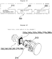
- a rectangular support frame 230a is detachably coupled to the front surface of a head of the first robot arm, which faces the hexagonal coil antenna forming module.
- the second robot arm 240 is arranged at an angle of 60° with respect to the first robot arm so as to be aligned in one-to-one correspondence with the hexagonal coil antenna forming module, and is sequentially rotated by receiving the rotational force from the rotary member, thereby supporting the rear end of a planar coil antenna formed by the hexagonal coil antenna forming module so that the surface of the planar coil antenna is planarized.
- the second robot arm includes a second limit switch sensor, which is provided on the surface of the second robot arm, so as to be aligned in one-to-one correspondence with the hexagonal coil antenna forming module.
- a rectangular support frame 240a is detachably coupled to the front surface of a head of the second robot arm, which faces the hexagonal coil antenna forming module.
- the third robot arm 250 is arranged at an angle of 60° with respect to the second robot arm so as to be aligned in one-to-one correspondence with the hexagonal coil antenna forming module, and is sequentially rotated by receiving the rotational force from the rotary member, thereby supporting the rear end of a planar coil antenna formed by the hexagonal coil antenna forming module so that the surface of the planar coil antenna is planarized.
- the third robot arm includes a third limit switch sensor, which is provided on the surface of the third robot arm, so as to be aligned in one-to-one correspondence with the hexagonal coil antenna forming module.
- a rectangular support frame 250a is detachably coupled to the front surface of a head of the third robot arm, which faces the hexagonal coil antenna forming module.
- the fourth robot arm 260 is arranged at an angle of 60° with respect to the third robot arm so as to be aligned in one-to-one correspondence with the hexagonal coil antenna forming module, and is sequentially rotated by receiving the rotational force from the rotary member, thereby supporting the rear end of a planar coil antenna formed by the hexagonal coil antenna forming module so that the surface of the planar coil antenna is planarized.
- the fourth robot arm includes a fourth limit switch sensor, which is provided on the surface of the fourth robot arm, so as to be aligned in one-to-one correspondence with the hexagonal coil antenna forming module.
- a rectangular support frame 260a is detachably coupled to the front surface of a head of the fourth robot arm, which faces the hexagonal coil antenna forming module.
- the fifth robot arm 270 is arranged at an angle of 60° with respect to the fourth robot arm so as to be aligned in one-to-one correspondence with the hexagonal coil antenna forming module, and is sequentially rotated by receiving the rotational force from the rotary member, thereby supporting the rear end of a planar coil antenna formed by the hexagonal coil antenna forming module so that the surface of the planar coil antenna is planarized.
- the fifth robot arm includes a fifth limit switch sensor, which is provided on the surface of the fifth robot arm, so as to be aligned in one-to-one correspondence with the hexagonal coil antenna forming module.
- a rectangular support frame 270a is detachably coupled to the front surface of a head of the fifth robot arm, which faces the hexagonal coil antenna forming module.
- the sixth robot arm 280 is arranged at an angle of 60° with respect to the fifth robot arm so as to be aligned in one-to-one correspondence with the hexagonal coil antenna forming module, and is sequentially rotated by receiving the rotational force from the rotary member, thereby supporting the rear end of a planar coil antenna formed by the hexagonal coil antenna forming module so that the surface of the planar coil antenna is planarized.
- the sixth robot arm includes a sixth limit switch sensor, which is provided on the surface of the sixth robot arm, so as to be aligned in one-to-one correspondence with the hexagonal coil antenna forming module.
- a rectangular support frame 280a is detachably coupled to the front surface of a head of the sixth robot arm, which faces the hexagonal coil antenna forming module.
- hexagonal coil antenna forming module 300 Next, the hexagonal coil antenna forming module 300 according to the present invention will be described.
- the hexagonal coil antenna forming module 300 is located around the rotary-type robot drive module so as to face the rotary-type robot drive module in a one-to-one correspondence alignment manner, and is operated under the control of the PLC control module so as to automatically form a planar coil antenna having a planarized surface by performing planar-coil winding, pressing, cold-pressing, transferring, air spraying, and preheating processes.
- the hexagonal coil antenna forming module includes a hybrid-type coil antenna winding unit 310, a press-type planarization drive module 320, a hybrid-type planarization drive module 330, a completed planar coil antenna gripping module 340, an air spray module 350, and a preheating module 360.
- the hybrid-type coil antenna winding unit 310 faces the rotary-type robot drive module in a one-to-one correspondence alignment manner, and is operated under the control of the PLC control module.
- the hybrid-type coil antenna winding unit receives a rectangular planar wire, moves linearly to the first, second, third, fourth, fifth and sixth robot arms of the rotary-type robot drive module, and winds a donut-shaped planar coil antenna on each of the first, second, third, fourth, fifth and sixth robot arms while performing rotational movement.
- the hybrid-type coil antenna winding unit includes a planar wire transfer unit 311, a first X-axis transfer air cylinder 312, a rotary-type head unit 313, and a wire cutting unit 314.
- the planar wire transfer unit 311 serves to transfer a rectangular planar wire wound on a planar wire drum to the rotary-type head unit.
- the first X-axis transfer air cylinder 312 is located at the rear end of the rotary-type head unit, and serves to move the rotary-type head unit linearly along the X-axis, i.e., in the horizontal direction, with respect to the rotary-type robot drive module.
- a second limit switch is mounted to a portion of the first X-axis transfer air cylinder, and a drive signal of the first X-axis transfer air cylinder is transmitted from the PLC control module.
- the rotary-type head unit 313 is located at the front end of the first X-axis transfer air cylinder, and serves to form a donut-shaped planar coil antenna by winding the rectangular planar wire on the rectangular support frames of the first, second, third, fourth, fifth and sixth robot arms.
- the wire cutting unit 314 serves to cut the leftover rectangular planar wire after the rectangular planar wire has been wound on the rectangular support frames of the first, second, third, fourth, fifth and sixth robot arms.
- the wire cutting unit is located inside the rotary-type head unit.
- the wire cutting unit moves linearly from the inside of the rotary-type head unit in the outward direction so as to protrude from the rotary-type head unit, and cuts the leftover rectangular planar wire after the rectangular planar wire has been wound on the rectangular support frames of the first, second, third, fourth, fifth and sixth robot arms.
- the press-type planarization drive module 320 faces the rotary-type robot drive module in a one-to-one correspondence alignment manner, and is operated under the control of the PLC control module so as to primarily planarize the surface of the planar coil antenna by applying the pressing force to the planar coil antenna wound on each of the first, second, third, fourth, fifth and sixth robot arms.
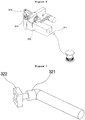
- the press-type planarization drive module includes a second X-axis transfer air cylinder 321 and a first upright-type press unit 322.
- the second X-axis transfer air cylinder 321 is located at the rear end of the first upright-type press unit, and serves to move the first upright-type press unit linearly along the X-axis, i.e., in the horizontal direction, with respect to the rotary-type robot drive module.
- a third limit switch is mounted to a portion of the second X-axis transfer air cylinder, and a drive signal of the second X-axis transfer air cylinder is transmitted from the PLC control module.
- the first upright-type press unit 322 is located at the front end of the second X-axis transfer air cylinder, and serves to primarily planarize the surface of the planar coil antenna by applying the pressing force to the planar coil antenna wound on each of the first, second, third, fourth, fifth and sixth robot arms.
- the hybrid-type planarization drive module 330 faces the rotary-type robot drive module in a one-to-one correspondence alignment manner, and is operated under the control of the PLC control module so as to secondarily planarize the surface of the planar coil antenna by applying the pressing force to the primarily planarized planar coil antenna wound on each of the first, second, third, fourth, fifth and sixth robot arms while air-cooling the planar coil antenna.
- the hybrid-type planarization drive module includes a third X-axis transfer air cylinder 331, a second upright-type press unit 332, and a cooling air spray nozzle 333.
- the third X-axis transfer air cylinder 331 is located at the rear end of the second upright-type press unit, and serves to move the second upright-type press unit linearly along the X-axis, i.e. in the horizontal direction, with respect to the rotary-type robot drive module.
- a fourth limit switch is mounted to a portion of the third X-axis transfer air cylinder, and a drive signal of the third X-axis transfer air cylinder is transmitted from the PLC control module.
- the second upright-type press unit 332 is located at the front end of the third X-axis transfer air cylinder, and serves to secondarily planarize the surface of the planar coil antenna by applying the pressing force to the primarily planarized planar coil antenna wound on each of the first, second, third, fourth, fifth and sixth robot arms.
- the cooling air spray nozzle 333 is located at a portion of the second upright-type press unit, and serves to spray cooling air toward the primarily planarized planar coil antenna.
- the completed planar coil antenna gripping module 340 faces the rotary-type robot drive module in a one-to-one correspondence alignment manner, and is operated under the control of the PLC control module so as to transfer the planar coil antenna, on which the secondary planarization has been completely performed, from each of the first, second, third, fourth, fifth and sixth robot arms to the outside by gripping the same using grippers.
- the completed planar coil antenna gripping module includes a gripping robot body 341, a first Z-axis transfer air cylinder 342, a fourth X-axis transfer air cylinder 343, a first gripper 344, a second gripper 345, a third gripper 346, a fourth gripper 347, and a gripper drive unit 348.
- the gripping robot body 341 serves to protect various devices from external pressure and support the same.
- the first Z-axis transfer air cylinder 342 is formed at the front end of the gripping robot body in the vertical direction, and serves to move the grippers along the ( ⁇ ) Z-axis.
- the +Z-axis refers to the upward direction along a vertical line
- the -Z-axis refers to the downward direction along the vertical line
- a fifth limit switch is mounted to a portion of the first Z-axis transfer air cylinder 342, and a drive signal of the first Z-axis transfer air cylinder is transmitted from the PLC control module.
- the fourth X-axis transfer air cylinder 343 is located at the rear ends of the first, second, third and fourth grippers, and serves to move the first, second, third and fourth grippers linearly along the X-axis, i.e., in the horizontal direction, with respect to the rotary-type robot drive module.
- a sixth limit switch is mounted to a portion of the fourth X-axis transfer air cylinder, and a drive signal of the fourth X-axis transfer air cylinder is transmitted from the PLC control module.
- the first gripper 344 is operated by the gripper drive unit so as to grip the first side of the completed planar coil antenna.
- the second gripper 345 is operated by the gripper drive unit so as to grip the second side of the completed planar coil antenna.
- the third gripper 346 is operated by the gripper drive unit so as to grip the third side of the completed planar coil antenna.
- the fourth gripper 347 is operated by the gripper drive unit so as to grip the fourth side of the completed planar coil antenna.
- the gripper drive unit 348 is located at the top ends of the first, second, third and fourth grippers, and serves to operate the first, second, third and fourth grippers so that the grippers perform gripping or releasing operations.
- the air spray module 350 faces the rotary-type robot drive module in a one-to-one correspondence alignment manner, and is operated under the control of the PLC control module so as to remove remaining foreign substances from each of the first, second, third, fourth, fifth and sixth robot arms by spraying air to the robot arms, from which the completed planar coil antenna has been transferred.
- the air spray module includes an air spray nozzle 351 and an air tank 352.
- the preheating module 360 faces the rotary-type robot drive module in a one-to-one correspondence alignment manner, and is operated under the control of the PLC control module so as to preheat each of the first, second, third, fourth, fifth and sixth robot arms by applying heat to the robot arms, to which air has been sprayed.
- the preheating module includes a heating nozzle 361 and a heater 362.
- the touch screen unit 400 is located on the right portion of the top surface of the main body, and serves to display input keys and the operation state of devices on a screen.
- the PLC control module 500 is connected to the rotary-type robot drive module, the hexagonal coil antenna forming module, and the touch screen unit, and sequentially controls the overall operation of each device.
- the PLC control module controls the operation of the rotary-type robot drive module and the hexagonal coil antenna forming module in response to the key input value input through the touch screen unit so that a planar coil antenna having a planarized surface is automatically formed through the planar-coil winding, pressing, cold-pressing, transferring, air spraying, and preheating processes.
- the PLC control module includes a central processing unit (CPU) 510, an input/output unit 520, and a power supply unit 530.
- CPU central processing unit
- input/output unit 520 input/output unit
- power supply unit 530 power supply unit
- the central processing unit (CPU) 510 serves to perform one-to-one sequence control in response to the key input value input through the touch screen unit, to compare a value measured by a sensor, which is input to an input side of the CPU, with a predetermined reference value, and to determine speeds, moving directions and moving times of the rotary-type robot drive module and the hexagonal coil antenna forming module under program control.
- the input/output unit 520 serves to receive values measured by the first limit sensor, the second limit sensor, the third limit sensor, the fourth limit sensor, the fifth limit sensor, and the sixth limit sensor, which are connected to an input side of the input/output unit, to transmit the received values to the central processing unit (CPU), and to output control commands of the CPU to the servo motor, the first X-axis transfer air cylinder, the rotary-type head unit, the wire cutting unit, the second X-axis transfer air cylinder, the third X-axis transfer air cylinder, the cooling air spray nozzle, the first Z-axis transfer air cylinder, the fourth X-axis transfer air cylinder, the air spray nozzle, and the heating nozzle, which are connected to an output side of the input/output unit.
- CPU central processing unit
- the input/output unit includes a photocoupler for preventing noise from being transmitted from external devices to the central processing unit (CPU) and an LED module for displaying the state of the respective contacts of the input and output sides.
- CPU central processing unit
- LED module for displaying the state of the respective contacts of the input and output sides.
- the power supply unit 530 serves to supply power to the respective devices.
- the input keys and the operation state of the devices are displayed on the screen through the touch screen unit.
- the rotary-type robot drive module and the hexagonal coil antenna forming module are operated by the PLC control module in response to the key input value input through the touch screen unit.
- the hybrid-type coil antenna winding unit of the hexagonal coil antenna forming module is operated to receive the rectangular planar wire, to move linearly toward the first robot arm of the rotary-type robot drive module, to wind it to form the donut-shaped planar coil antenna on the first robot arm while performing rotational movement, and to cut the leftover rectangular planar wire using the wire cutting unit after the rectangular planar wire has been wound on the rectangular support frame.
- the first robot arm of the rotary-type robot drive module is sequentially rotated toward the press-type planarization drive module of the hexagonal coil antenna forming module, and the press-type planarization drive module performs primary planarization on the surface of the planar coil antenna by applying the pressing force to the planar coil antenna wound on the first robot arm.
- the first robot arm of the rotary-type robot drive module is sequentially rotated toward the hybrid-type planarization drive module of the hexagonal coil antenna forming module, and the hybrid-type planarization drive module performs secondary planarization on the surface of the planar coil antenna by applying the pressing force to the primarily planarized planar coil antenna wound on the first robot arm while air-cooling the planar coil antenna.
- the first robot arm of the rotary-type robot drive module is sequentially rotated toward the completed planar coil antenna gripping module of the hexagonal coil antenna forming module, and the completed planar coil antenna gripping module grips the planar coil antenna, on which the secondary planarization has been completely performed, from the first robot arm, and transfers the planar coil antenna to the outside.
- the first robot arm of the rotary-type robot drive module is sequentially rotated toward the air spray module of the hexagonal coil antenna forming module, and the air spray module removes remaining foreign substances from the first robot arm by spraying air to the first robot arm, from which the completed planar coil antenna has been transferred.
- the first robot arm of the rotary-type robot drive module is sequentially rotated toward the preheating module of the hexagonal coil antenna forming module, and the preheating module preheats the first robot arm by applying heat to the first robot arm, to which air has been sprayed.
- a planar coil antenna having a planarized surface is also automatically formed at each of the second, third, fourth, fifth and sixth robot arms through the planar-coil winding, pressing, cold-pressing, transferring, air spraying, and preheating processes.
- the present invention is capable of automatically forming a planar coil antenna having a planarized surface by performing planar-coil winding, pressing, cold-pressing, transferring, air spraying, and preheating processes on a received rectangular planar wire while sequentially rotating in one place in a rotary manner, whereby all processes can be automated. Since the processes can be performed without a large number of workers, it is possible to reduce personnel expenses by 80% compared to the prior art.
- a rectangular planar coil antenna is manufactured, it is possible to manufacture a high-quality planar coil antenna having an evenly planarized surface by primarily planarizing the coil antenna using pressing force and secondarily planarizing the coil antenna using pressing force and a cold spray.
- a planar coil antenna having a planarized surface can be mass-produced by performing planar-coil winding, pressing, cold-pressing, transferring, air spraying, and preheating processes using first, second, third, fourth, fifth and sixth robot arms, which are operated under the control of a PLC control module. Therefore, the present invention has high industrial applicability.
Landscapes
- Engineering & Computer Science (AREA)
- Power Engineering (AREA)
- Manufacturing & Machinery (AREA)
- Physics & Mathematics (AREA)
- General Physics & Mathematics (AREA)
- Automation & Control Theory (AREA)
- Robotics (AREA)
- Mechanical Engineering (AREA)
- Details Of Aerials (AREA)
- Computer Networks & Wireless Communication (AREA)
Applications Claiming Priority (2)
| Application Number | Priority Date | Filing Date | Title |
|---|---|---|---|
| KR1020150147824A KR101771105B1 (ko) | 2015-10-23 | 2015-10-23 | 로터리형 평면코일안테나 스마트 자동제작장치 |
| PCT/KR2016/006834 WO2017069377A1 (ko) | 2015-10-23 | 2016-06-27 | 로터리형 평면코일안테나 스마트 자동제작장치 |
Publications (2)
| Publication Number | Publication Date |
|---|---|
| EP3367501A1 true EP3367501A1 (de) | 2018-08-29 |
| EP3367501A4 EP3367501A4 (de) | 2019-08-21 |
Family
ID=58557675
Family Applications (1)
| Application Number | Title | Priority Date | Filing Date |
|---|---|---|---|
| EP16857635.3A Withdrawn EP3367501A4 (de) | 2015-10-23 | 2016-06-27 | Rotierende intelligente automatische herstellungsvorrichtung für flachspulenantenne |
Country Status (5)
| Country | Link |
|---|---|
| US (1) | US20180358702A1 (de) |
| EP (1) | EP3367501A4 (de) |
| KR (1) | KR101771105B1 (de) |
| CN (1) | CN108370097B (de) |
| WO (1) | WO2017069377A1 (de) |
Families Citing this family (5)
| Publication number | Priority date | Publication date | Assignee | Title |
|---|---|---|---|---|
| CN108032328B (zh) * | 2017-12-18 | 2023-08-04 | 深圳市优必选科技有限公司 | 一种舵机组件、机器人关节结构及机器人 |
| CN109850704B (zh) * | 2019-02-27 | 2024-04-26 | 大连萌羽机械有限公司 | 一种飞机发动机卡箍减震组件及其制造工艺 |
| CN110957128B (zh) * | 2020-01-02 | 2020-10-09 | 涂旭平 | 一种智能回转式主副极线圈一体绕制机器人 |
| CN111145999B (zh) * | 2020-01-21 | 2022-02-25 | 科瓦力(宁波)精密器械有限公司 | 一种一体式智能主副极线圈绕制机器人 |
| CN113871193B (zh) * | 2021-09-27 | 2022-05-17 | 桂林电子科技大学 | 一种双位置圆周调控总成及其组成电抗器缠绕模具 |
Family Cites Families (12)
| Publication number | Priority date | Publication date | Assignee | Title |
|---|---|---|---|---|
| DE3337787A1 (de) * | 1983-09-16 | 1985-04-04 | Volex AG, Zürich | Schwingkreis fuer eine gegen diebstahl zu sichernde ware, verfahren zur herstellung eines schwingkreises und einrichtung zur ausfuehrung des verfahrens |
| US5507322A (en) * | 1993-12-14 | 1996-04-16 | Abb Power T&D Company Inc. | Device and method for forming planar disk transformer windings |
| KR20000074644A (ko) * | 1999-05-24 | 2000-12-15 | 이형도 | 편향 요크의 코일 권선장치 |
| US20020055822A1 (en) * | 2000-11-08 | 2002-05-09 | Paul Amadeo | Integrated welding and testing in the manufacture of smart cards |
| US6628240B2 (en) * | 2000-11-08 | 2003-09-30 | American Pacific Technology | Method and apparatus for rapid staking of antennae in smart card manufacture |
| EP2235667B1 (de) * | 2008-01-23 | 2012-10-10 | Smartrac IP B.V. | Herstellung einer chipkarte |
| JP5172767B2 (ja) * | 2009-04-02 | 2013-03-27 | 株式会社日立産機システム | 変圧器用複数線多段コイルの巻線装置 |
| JP2011129704A (ja) | 2009-12-17 | 2011-06-30 | Johnan Corp | 巻線方法及び巻線装置並びにアンテナ |
| KR101302387B1 (ko) * | 2011-05-28 | 2013-09-02 | 한상수 | 6축제어 기반의 안테나 코일 권선장치 |
| CN102623165B (zh) * | 2012-03-29 | 2014-05-28 | 腾普(常州)精机有限公司 | 铁芯自动加压检测机 |
| US9812745B2 (en) * | 2012-12-28 | 2017-11-07 | Semiconductor Energy Laboratory Co., Ltd. | Power storage device |
| KR101525235B1 (ko) | 2015-03-02 | 2015-06-01 | 홍국선 | 편각코일 융착장치 |
-
2015
- 2015-10-23 KR KR1020150147824A patent/KR101771105B1/ko not_active Expired - Fee Related
-
2016
- 2016-06-27 CN CN201680072450.9A patent/CN108370097B/zh active Active
- 2016-06-27 EP EP16857635.3A patent/EP3367501A4/de not_active Withdrawn
- 2016-06-27 WO PCT/KR2016/006834 patent/WO2017069377A1/ko not_active Ceased
- 2016-06-27 US US15/777,010 patent/US20180358702A1/en not_active Abandoned
Also Published As
| Publication number | Publication date |
|---|---|
| KR20170047565A (ko) | 2017-05-08 |
| US20180358702A1 (en) | 2018-12-13 |
| EP3367501A4 (de) | 2019-08-21 |
| KR101771105B1 (ko) | 2017-08-24 |
| WO2017069377A1 (ko) | 2017-04-27 |
| CN108370097B (zh) | 2019-04-26 |
| CN108370097A (zh) | 2018-08-03 |
Similar Documents
| Publication | Publication Date | Title |
|---|---|---|
| US20180358702A1 (en) | Rotary-type smart automatic manufacturing apparatus for planar coil antenna | |
| TWI554022B (zh) | 智慧馬達的識別碼設定方法及應用其之多軸控制裝置 | |
| CN101154743B (zh) | 电池装配装置和方法 | |
| CN204966271U (zh) | 自动化高效变压器卷铁芯装置 | |
| CN204315483U (zh) | 一种小型漏电断路器重合闸装置 | |
| CN105336486A (zh) | 变压器加工装置及其加工工艺 | |
| CN210575528U (zh) | 一种多工位空心线圈绕线机 | |
| CN102324800A (zh) | 集约式旋转伸缩装置 | |
| CN210093078U (zh) | 一种漆包线自动脱漆机 | |
| CN207691182U (zh) | 一种端子机的上料装置 | |
| CN203150484U (zh) | 一种接触器线圈单元自动绞线设备 | |
| CN208977974U (zh) | 带有自动收放料装置的高速成型装置 | |
| CN105938349B (zh) | 标牌自动化安装控制系统 | |
| CN204220700U (zh) | 一种半自动弯板机 | |
| CN205230811U (zh) | 绕线机 | |
| CN204361953U (zh) | 一种可远程控制的三相电动机装置 | |
| CN210655628U (zh) | 一种漆包线生产用卷取装置 | |
| CN204057360U (zh) | 一种送料转盘装置 | |
| KR20120041050A (ko) | 배선반 및 이를 이용한 원격 제어 배선반 관리 시스템 | |
| CN113909066A (zh) | 一种用于绝缘涂覆机器人的多路遥控通信方法 | |
| CN205748374U (zh) | 一种立体视觉扫描定位装置 | |
| CN208969999U (zh) | 工业机器人综合技术训练平台 | |
| CN221281418U (zh) | 平料现场振动时间同步计时系统 | |
| CN110988389B (zh) | 抗风监测装置及方法 | |
| CN203748186U (zh) | 料带转料机 |
Legal Events
| Date | Code | Title | Description |
|---|---|---|---|
| PUAI | Public reference made under article 153(3) epc to a published international application that has entered the european phase |
Free format text: ORIGINAL CODE: 0009012 |
|
| 17P | Request for examination filed |
Effective date: 20180522 |
|
| AK | Designated contracting states |
Kind code of ref document: A1 Designated state(s): AL AT BE BG CH CY CZ DE DK EE ES FI FR GB GR HR HU IE IS IT LI LT LU LV MC MK MT NL NO PL PT RO RS SE SI SK SM TR |
|
| AX | Request for extension of the european patent |
Extension state: BA ME |
|
| DAV | Request for validation of the european patent (deleted) | ||
| DAX | Request for extension of the european patent (deleted) | ||
| A4 | Supplementary search report drawn up and despatched |
Effective date: 20190722 |
|
| RIC1 | Information provided on ipc code assigned before grant |
Ipc: H01Q 7/00 20060101AFI20190716BHEP Ipc: H01F 41/074 20160101ALI20190716BHEP Ipc: H01F 41/09 20160101ALI20190716BHEP Ipc: B25J 11/00 20060101ALI20190716BHEP Ipc: H01Q 1/24 20060101ALI20190716BHEP Ipc: G05B 19/05 20060101ALI20190716BHEP |
|
| GRAP | Despatch of communication of intention to grant a patent |
Free format text: ORIGINAL CODE: EPIDOSNIGR1 |
|
| INTG | Intention to grant announced |
Effective date: 20200504 |
|
| RIN1 | Information on inventor provided before grant (corrected) |
Inventor name: CHO, OH-SUNG Inventor name: LEE, GYE-SAN |
|
| STAA | Information on the status of an ep patent application or granted ep patent |
Free format text: STATUS: THE APPLICATION IS DEEMED TO BE WITHDRAWN |
|
| 18D | Application deemed to be withdrawn |
Effective date: 20200915 |