EP3366552B1 - Appareil d'assistance au stationnement - Google Patents
Appareil d'assistance au stationnement Download PDFInfo
- Publication number
- EP3366552B1 EP3366552B1 EP18159253.6A EP18159253A EP3366552B1 EP 3366552 B1 EP3366552 B1 EP 3366552B1 EP 18159253 A EP18159253 A EP 18159253A EP 3366552 B1 EP3366552 B1 EP 3366552B1
- Authority
- EP
- European Patent Office
- Prior art keywords
- vehicle
- processing
- predetermined condition
- satisfied
- steering
- Prior art date
- Legal status (The legal status is an assumption and is not a legal conclusion. Google has not performed a legal analysis and makes no representation as to the accuracy of the status listed.)
- Active
Links
Images


Classifications
-
- B—PERFORMING OPERATIONS; TRANSPORTING
- B62—LAND VEHICLES FOR TRAVELLING OTHERWISE THAN ON RAILS
- B62D—MOTOR VEHICLES; TRAILERS
- B62D15/00—Steering not otherwise provided for
- B62D15/02—Steering position indicators ; Steering position determination; Steering aids
- B62D15/027—Parking aids, e.g. instruction means
- B62D15/0285—Parking performed automatically
-
- B—PERFORMING OPERATIONS; TRANSPORTING
- B60—VEHICLES IN GENERAL
- B60W—CONJOINT CONTROL OF VEHICLE SUB-UNITS OF DIFFERENT TYPE OR DIFFERENT FUNCTION; CONTROL SYSTEMS SPECIALLY ADAPTED FOR HYBRID VEHICLES; ROAD VEHICLE DRIVE CONTROL SYSTEMS FOR PURPOSES NOT RELATED TO THE CONTROL OF A PARTICULAR SUB-UNIT
- B60W30/00—Purposes of road vehicle drive control systems not related to the control of a particular sub-unit, e.g. of systems using conjoint control of vehicle sub-units
- B60W30/06—Automatic manoeuvring for parking
-
- B—PERFORMING OPERATIONS; TRANSPORTING
- B60—VEHICLES IN GENERAL
- B60W—CONJOINT CONTROL OF VEHICLE SUB-UNITS OF DIFFERENT TYPE OR DIFFERENT FUNCTION; CONTROL SYSTEMS SPECIALLY ADAPTED FOR HYBRID VEHICLES; ROAD VEHICLE DRIVE CONTROL SYSTEMS FOR PURPOSES NOT RELATED TO THE CONTROL OF A PARTICULAR SUB-UNIT
- B60W50/00—Details of control systems for road vehicle drive control not related to the control of a particular sub-unit, e.g. process diagnostic or vehicle driver interfaces
- B60W50/08—Interaction between the driver and the control system
- B60W50/14—Means for informing the driver, warning the driver or prompting a driver intervention
Definitions
- the embodiment disclosed herein relates to a parking assistance apparatus.
- a parking assistance system which controls driving of a vehicle when a vehicle enters or exits from a parking space is implemented by various methods, using an ultrasonic senor, a camera, or the like.
- the parking assistance system it is necessary to study a method of transferring the driving of the vehicle to the driver when entering or exiting of the vehicle to or from the parking space is completed from the view point of safety, ease of understanding, and ease of use.
- the parking assistance system determines whether or not control of the driving of the vehicle is terminated, depending on whether or not the vehicle reaches a target position, or whether or not a pre-set exiting condition is satisfied. See, e.g., JP 2014-121984 A (Reference 1).
- the parking assistance system terminates the control of the driving of the vehicle with the expectation that the driver will perform driving simultaneously when the control of driving of the vehicle is terminated.
- the vehicle may approach an obstacle in the vicinity thereof due to the delayed driving of the driver.
- EP 1 864 881 and DE 10 2012 203 235 which is considered as the closest prior art, are also known and disclose vehicle driving manoeuver systems for automatic parking apparatuses.
- a parking assistance apparatus includes the features of appended claim 1.
- it includes a control unit configured to: perform a steering control processing that controls steering of a vehicle and a vehicle speed control processing that controls a traveling speed of the vehicle when the vehicle enters or exits from a parking space; terminate a first processing that is one of the steering control processing and the vehicle speed control processing when a predetermined condition is satisfied after the vehicle starts to enter or exit from the parking space; and continue a second processing that is one of the steering control processing and the vehicle speed control processing other than the first processing. Accordingly, as an example, after the entering or exiting of the vehicle to or from the parking space is completed, the driving of the vehicle can be safely transferred to the driver.
- the predetermined condition is that it is determined that the entering or exiting of the vehicle to or from the parking space is completed. Accordingly, as an example, after the entering or exiting of the vehicle to or from the parking space is completed, the driving of the vehicle can be safely transferred to the driver.
- the parking assistance apparatus further includes a notification unit configured to provide at least one of a notification that the predetermined condition is satisfied, a notification that the first processing is terminated, and a notification that the second processing is continued, in a case where the predetermined condition is satisfied. Accordingly, as an example, it is possible to reliably transfer the driving of the vehicle to the driver.
- the notification unit outputs at least one of sound indicating that the predetermined condition is satisfied, sound indicating that the first processing is terminated, and sound indicating that the second processing is continued, in the case where the predetermined condition is satisfied. Accordingly, as an example, it is possible to reliably transfer the driving of the vehicle to the driver.
- the notification unit displays, on a display device, at least one of a message indicating that the predetermined condition is satisfied, a message indicating that the first processing is terminated, and a message indicating that the second processing is continued, in the case where the predetermined condition is satisfied. Accordingly, as an example, it is possible to reliably transfer the driving of the vehicle to the driver.
- the control unit cancels continuation of the second processing, in a case where an operation of canceling the continuation of the second processing is performed by a driver of the vehicle or an operation of the vehicle to cancel the continuation of the second processing is performed while the second processing is continued after the predetermined condition is satisfied. Accordingly, the driver can be ready to drive the vehicle. Thus, even if both of the steering control processing and the vehicle speed control processing are terminated, the continuation of the second processing can be terminated in the case where the possibility that the driving of the vehicle is delayed is low.
- the control unit cancels the continuation of the second processing when the second processing is continued for a predetermined time after the predetermined condition is satisfied. Accordingly, the driver can be ready to drive the vehicle. Thus, even if both of the steering control processing and the vehicle speed control processing are terminated, the continuation of the second processing can be terminated in a case where the possibility that the driving of the vehicle is delayed is low.
- the control unit continues both of the operation control processing and the vehicle speed control processing even if steering or speed operation of the vehicle is performed by the driver of the vehicle before the predetermined condition is satisfied. Accordingly, as an example, it is possible to prevent the vehicle from running out to a lane, and from rapidly approaching an obstacle due to the delayed driving of the driver before the entering or exiting of the vehicle to or from the parking space is completed.
- Fig. 1 is a perspective view illustrating an exemplary vehicle to which a parking assistance apparatus according to an example is applied in the state where a portion of the vehicle interior is seen through.
- a vehicle 1 may be an automobile that uses an internal combustion engine as a driving source (an internal combustion engine automobile), may be an automobile that uses an electric motor as a driving source (an electric automobile, a fuel battery automobile, or the like), or may be an automobile that uses both of the internal combustion engine and the electric motor as driving sources (a hybrid automobile).
- the vehicle 1 may be equipped with various transmissions and various apparatus (a system, a component, and the like) required for driving the internal combustion engine or the electric motor.
- the types, number, layout and the like of the apparatuses related to the driving of wheels 3 in the vehicle 1 can be set in various ways.
- the vehicle 1 includes a vehicle body 2, a steering unit 4, an accelerating operation unit 5, a braking operation unit 6, a gear-shifting operation unit 7, and a monitoring device 11.
- the vehicle body 2 has a vehicle interior 2a into which an occupant of the vehicle 1 gets.
- the steering unit 4, the accelerating operation unit 5, the braking operation unit 6, the gear-shifting operation unit 7, a display device 8, a sound output device 9, an operation input unit 10, and the like are installed in a state of facing a seat 2b of a driver as the occupant.
- the steering unit 4 is, for example, a steering wheel that protrudes from a dashboard.
- the accelerating operation unit 5 is, for example, an accelerator that is positioned under the driver's foot.
- the braking operation unit 6 is, for example, a brake pedal that is positioned under the driver's foot.
- the gear-shifting operation unit 7 is, for example, a shift lever that protrudes from a center console.
- the monitoring device 11 is provided in, for example, a center portion of the dashboard in the vehicle width direction (i.e., the left-right direction).
- the monitoring device 11 may have, for example, a function of a navigation system, a sound system, or the like.
- the monitoring device 11 has the display device 8, the sound output device 9, and the operation input unit 10.
- the monitoring device 11 may have various input units, such as a switch, a dial, a joystick, and a push button.
- the display device 8 is configured with a liquid crystal display (LCD), an organic electro luminescence display (OLED), or the like, and is able to display thereon various images based on image data.
- the sound output device 9 is configured with a speaker or the like, and various types of sound are output from the sound output device 9 based on sound data.
- the sound output device 9 may be provided at a position other than the monitoring device 11 within the vehicle interior 2a.
- the operation input unit 10 is configured with a touch panel or the like, and enables various pieces of information to be input by an occupant. Furthermore, the operation input unit 10 is provided on a display screen of the display device 8, and is able to transmit therethrough an image that is displayed on the display device 8. Accordingly, the operation input unit 10 enables an image displayed on the display screen of the display device 8 to be visually recognized by the occupant. The operation input unit 10 receives input of various pieces of information from the occupant by detecting the occupant's touch operation on the display screen of the display device 8.
- Fig. 2 is a top plan view illustrating the exemplary vehicle according to the example.
- the vehicle 1 is a four-wheeled automobile or the like, and has two left and right front wheels 3F and two left and right rear wheels 3R. All or some of the four wheels 3 can be steered.
- the vehicle 1 has a plurality of imaging units 15.
- Each of the imaging unit 15 is a digital camera that has an imaging device such as a charge-coupled device (CCD) or a CMOS image sensor (CIS).
- the imaging units 15 are able to image the vicinity of the vehicle 1 at a predetermined frame rate. Then, the imaging units 15 output image data of a captured image obtained by imaging the vicinity of the vehicle 1.
- the imaging units 15 include two imaging units 15a and 15b.
- the imaging unit 15a is provided on a rear end portion 2e (for example, under a door 2h of the rear trunk) of the vehicle body 2, and is able to image the rear side of the vehicle 1.
- the imaging unit 15b is provided on a front end portion 2c of the vehicle body 2 (for example, the front bumper), and is able to image the front side of the vehicle 1.
- the imaging units 15 include two imaging units 15a and 15b in the example, the imaging units may include three or more imaging units. In that case, the imaging units 15 may be provided on the side surfaces of the vehicle body 2, and may be set to image the lateral sides of the vehicle 1.
- the vehicle 1 has a plurality of distance measuring sensors 16.
- the distance measuring sensors 16 emit light such as a laser beam, and receive light reflected from an obstacle, such as another vehicle, that is present around the vehicle 1. Then, based on the result of light reception from the obstacle, the distance measuring sensor 16 transmits, to an ECU 24, distance information, which enables a distance from the vehicle 1 to the obstacle to be specified.
- the distance measuring sensor 16 may transmit the distance from the vehicle 1 to the obstacle to the ECU 24 as the distance information, and may transmit a light-emitting time from the light measuring sensor 16 and a light-receiving time by the light measuring sensor 16 to the ECU 24 as distance information.
- a distance measuring sensor 16a is provided on the rear end portion 2e of the vehicle body 2 so as to detect a distance to an obstacle existing in rear of the vehicle 1.
- a distance measuring sensor 16b is provided on the front end portion 2c of the vehicle body 2 so as to detect a distance to an obstacle existing in front of the vehicle 1.
- Fig. 3 is a block diagram illustrating an exemplary functional configuration of the vehicle according to the example.
- the vehicle 1 includes a steering system 13, a brake system 18, a steering angle sensor 19, an accelerator sensor 20, a shift sensor 21, a wheel speed sensor 22, an in-vehicle network 23, and the electronic control unit (ECU) 24.
- ECU electronice control unit
- the monitoring device 11, the steering system 13, the distance measuring sensor 16, the brake system 18, the steering angle sensor 19, the accelerator sensor 20, the shift sensor 21, the wheel speed sensor 22, and the ECU 24 are electrically connected to each other through the in-vehicle network 23 that is an electric communication line.
- the in-vehicle network 23 is configured with a controller area network (CAN) or the like.
- the steering system 13 is an electric power steering system, a steer-by-wire (SBW) system, or the like.
- the steering system 13 has an actuator 13a and a torque sensor 13b. Then, the steering system 13 is electrically controlled by the ECU 24 or the like, and operates the actuator 13a so as to add torque to supplement a steering force for the steering unit 4, thereby steering the wheel 3.
- the torque sensor 13b detects torque that is given to the steering unit 4 by the driver, and transmits the detection result to the ECU 24.
- the brake system 18 includes an anti-lock brake system (ABS) that suppresses locking of the brake of the vehicle 1, a sideslip prevention device (electronic stability control (ESC)) that suppresses the sideslip of the vehicle 1 when cornering, an electric brake system that assists the brake by increasing a brake force, and a brake-by-wire (BBW).
- ABS anti-lock brake system
- ESC electronic stability control
- BBW brake-by-wire
- the brake system 18 has an actuator 18a and a brake sensor 18b.
- the brake system 18 is electrically controlled by the ECU 24 or the like, and imparts a braking force to the wheels 3 through the actuator 18a.
- the brake system 18 detects indications of locking of the brake, idling of the wheels 3, sideslip, and the like, from a difference in revolution between the left and right wheels 3 and the like, and thus performs control that suppresses the locking of the brake, the idling of the wheels 3, and the sideslip.
- the brake sensor 18b is a displacement sensor that detects the position of a brake pedal as a movable portion of the braking operation unit 6, and transmits the position detection result of the brake pedal to the ECU 24.
- the steering angle sensor 19 is a sensor that detects a steering amount of the steering unit 4 such as a steering wheel.
- the steering angle sensor 19 is configured with a Hall element or the like, detects a rotation angle of a rotating portion of the steering unit 4 as the steering amount, and transmits the detection result to the ECU 24.
- the accelerator sensor 20 is a displacement sensor that detects a position of an accelerator as a movable portion of the accelerating operation unit 5, and transmits the detection result to the ECU 24.
- the shift sensor 21 is a sensor that detects a position of a movable portion (a bar, an arm, a button, or the like) of the gear-shifting operation unit 7, and transmits the detection result to the ECU 24.
- the wheel speed sensor 22 is a sensor that has a Hall element or the like and detects the rotation amount of the wheels 3 or the number of revolutions of the wheels 3 per unit time, and transmits the detection result to the ECU 24.
- the ECU 24 is an example of the parking assistance apparatus that controls the driving of the vehicle 1 when causing the vehicle 1 to enter a parking position or when causing the vehicle 1 to exit from the parking position by controlling the steering system 13, the brake system 18, and the gear-shifting operation unit 7 through the in-vehicle network 23.
- the ECU 24 is configured with a computer or the like.
- the ECU 24 includes a central processing unit (CPU) 24a, a read-only memory (ROM) 24b, a random access memory 24c, a display control unit 24d, a sound control unit 24e, and a solid state drive (SSD) 24f.
- the CPU 24a, the ROM 24b, and the RAM 24c may be mounted on the same circuit substrate.
- the CPU 24a reads a program stored in a non-volatile memory device, such as the ROM 24b, and performs various computing processing operations according to the program. For example, the CPU 24a performs an image processing on image data displayed on the display device 8, calculation of a distance to an obstacle existing around the vehicle 1, setting of a parking position, computing of a path to the parking position, for the vehicle 1, and control of the driving of the vehicle 1, and so forth.
- the SSD 24f is a rewritable non-volatile memory unit, which continuously stores data acquired from the CPU 24a even in a case where the ECU 24 is powered off.
- the ECU 24 manages entire control of the vehicle 1 through the cooperation of hardware and software (a control program). For example, the ECU 24 identifies a parking frame or the like that is marked on a road around the vehicle 1 from a captured image obtained by the imaging of the imaging unit 15, sets a parking position within the parking frame, and controls the parking of the vehicle 1 to the parking position. Accordingly, the ECU 24 implements a function as the parking assistance apparatus.
- Fig. 4 is a block diagram illustrating an exemplary functional configuration of an ECU which is provided in the vehicle according to the example.
- the ECU 24 includes a drive control unit 401 and a notification unit 402.
- the CPU 24a executes a parking assistance processing program stored in the ROM 24b or the SSD 24f
- ECU 24 implements the functions of the drive control unit 401 and the notification unit 402.
- a part or the overall of each of the drive control unit 401 and the notification unit 402 may be configured with hardware such as a circuit.
- the drive control unit 401 executes a steering control processing that controls steering of the vehicle 1 by the steering unit 4 through the steering system 13, and a vehicle speed control processing that controls the traveling speed of the vehicle 1 through the accelerating operation unit 5 and the braking operation unit 6.
- the drive control unit 401 executes a gear-shifting control processing that controls switching of a shift range of the vehicle 1 by the gear-shifting operation unit 7.
- the drive control unit 401 terminates a first processing that is one of the steering control processing and the vehicle speed control processing, and continues a second processing that is the remaining one of the steering control processing and the vehicle speed control processing other than the first processing.
- the predetermined condition refers to a condition that is set in advance and is that it is determined that the entering or exiting of the vehicle 1 to or from the parking space is completed.
- the vehicle speed control processing can be continued such that the braking force exerted on the vehicle 1 can be prevented from being eliminated at the same time as the entering or exiting of the vehicle to or from the parking space is completed.
- the vehicle speed control processing can be continued such that the braking force exerted on the vehicle 1 can be prevented from being eliminated at the same time as the entering or exiting of the vehicle to or from the parking space is completed.
- the notification unit 402 displays, on the display device 8, at least one of a message indicating that the predetermined condition is satisfied, a message indicating that the first processing is terminated, and a message indicating that the second processing is continued. Accordingly, because a notification that the second processing is continued can be provided after the predetermined condition is satisfied, it is possible to reliably transfer the driving of the vehicle 1 to the driver.
- the notification unit 402 displays, on the display device 8, at least one of the message that the predetermined condition is satisfied, the message that the first processing is terminated, and the message that the second processing is continued.
- the notification unit 402 may output, from the sound output device 9, at least one of sound indicating that the predetermined condition is satisfied, sound indicating that the first processing is terminated, and sound indicating that the second processing is continued.
- Fig. 5 is a flowchart illustrating an exemplary flow of control processing of the vehicle to enter or exit from the parking space according to the example.
- the ECU 24 acquires image data from the imaging unit 15. Subsequently, based on the acquired image data, the ECU 24 identifies a parking frame or the like that is marked on the road around the vehicle 1, and sets a parking position within the parking frame. Subsequently, based on the set parking position and the current position of the vehicle 1, the ECU 24 computes a path to the parking position for the vehicle 1. Then, the ECU 24 controls the steering system 13, the brake system 18, and the gear-shifting operation unit 7 via the in-vehicle network 23 and causes the vehicle 1 to move along the computed path, thereby moving the vehicle 1 to the parking position.
- the ECU 24 acquires image data from the imaging unit 15. Subsequently, based on the acquired image data, the ECU 24 identifies an obstacle existing around the vehicle 1, and sets a position in which the obstacle is easily avoidable when the vehicle 1 is at the time of exiting, as an exiting position. For example, in a case where an instruction to cause the vehicle 1 to exit from the parking space from a state where the vehicle 1 is in parallel parking is input, the ECU 24 sets a position in which the opposite ends of the front bumper of the vehicle 1 in the vehicle-width direction protrude to a lane to which the vehicle 1 joins is set to an exiting position.
- the ECU 24 computes a path of the vehicle 1 to the exiting position. Then, the ECU 24 controls the steering system 13, the brake system 18, and gear-shifting operation unit 7 via the in-vehicle network 23 so as to cause the vehicle 1 to move along the computed path, thereby moving the vehicle 1 to the exiting position.
- the drive control unit 401 determines whether or not the entering or exiting of the vehicle to or from the parking space is completed (Step S501). In the example, in the case where the vehicle 1 enters the parking space, when the current position of the vehicle 1 is the parking position, the drive control unit 401 determines that the entering of the vehicle 1 to the parking space is completed. Furthermore, in the case where the vehicle exit from the parking space, when the current position of the vehicle 1 is the exiting position, the drive control unit 401 determines that the vehicle 1 has left the parking space.
- the drive control unit 401 continuously performs both of the operation control processing and the vehicle speed control processing.
- the driving of the vehicle 1 is controlled even if the driving of the vehicle 1 is performed by the driver before entering or exiting of the vehicle 1 to or from the parking space is completed, it is possible to prevent the vehicle 1 from running out to a lane and to prevent the vehicle 1 from rapidly approaching an obstacle due to the delayed driving of the driver before the entering or exiting of the vehicle 1 to or from the parking space is completed.
- Step S501 when it is determined that the entering or exiting of the vehicle 1 to or from the parking space is completed ("Yes" in Step S501), the drive control unit 401 sets a processing, which is one of the steering control processing and the vehicle speed control processing and has been set in advance, as a first processing, and terminates the first processing (Step S502). Moreover, the drive control unit 401 sets a processing, which is the remaining one of the steering control processing and the vehicle speed control processing and is other than the first processing, as a second processing, and continues the second processing (Step S503).
- the drive control unit 401 avoids a collision of the vehicle 1 with the obstacle with the second processing.
- the second processing is the steering control processing
- the drive control unit 401 steers the steering unit 4 in such a manner that the vehicle 1 does not collide with the obstacle.
- the second processing is the vehicle speed control processing
- the drive control unit 401 sets the traveling speed of the vehicle 1 to 0 such that the vehicle 1 does not collide with the obstacle.
- the drive control unit 401 is configured to detect that the vehicle 1 approaches the obstacle based on the image data acquired from the imaging unit 15 or the distance information output from the distance measuring sensor 16. Subsequently, the drive control unit 401 determines whether or not the second processing is continued for a predetermined time (for example, ten seconds) after a predetermined condition is satisfied (Step S504). In other words, the drive control unit 401 determines whether or not a predetermined time has elapsed after the predetermined condition is satisfied.
- a predetermined time for example, ten seconds
- Step S505 when it is determined that the second processing has been continued for a predetermined time after the predetermined condition is satisfied ("Yes" in Step S504), in other words, when it is determined the predetermined time has elapsed after the predetermined condition is satisfied, the drive control unit 401 cancels the continuation of the second processing (Step S505).
- the drive control unit 401 performs an operation of canceling the continuation of the second processing when an operation of cancelling the continuation of the second processing is performed by the driver of the vehicle 1 or an operation of the vehicle 1 to cancel continuing the second processing is performed, while the second processing is continued after the predetermined condition is satisfied.
- the driver can be ready to drive the vehicle 1, and even if both of the steering control processing and the vehicle speed control processing are terminated, the continuation of the second processing is terminated because the possibility that the driving of the vehicle 1 is delayed is low.
- the drive control unit 401 cancels the continuation of the steering control processing. Furthermore, in a case where the accelerating operation unit 5 or the controlling operation unit 6 is operated while the vehicle speed control processing as the second processing is continued after the predetermined condition is satisfied, the drive control unit 401 cancels the continuation of the braking control processing.
- the drive control unit 401 cancels the continuation of the steering control processing.
- the drive control unit 401 cancels the continuation of the vehicle speed control processing.
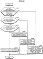
- FIG. 6 is a flowchart illustrating an exemplary flow of display processing of a message in the vehicle according to the example.
- Figs. 7 to 9 are views for describing an exemplary display processing of a message in the vehicle according to the example.
- the notification unit 402 determines whether or not one of the steering control processing and the vehicle speed control processing is completed (Step S601). In a case where both of the steering control processing and the vehicle speed control processing are performed ("No" in Step S601), the notification unit 402 displays, on the display device 8, a message indicating that both of the steering control processing and the vehicle speed control processing are continued (Step S602). In a case where it is determined that one of the steering control processing and the vehicle speed control processing is completed ("Yes" in Step S601), the notification unit 402 determines whether or not the vehicle speed control processing is completed (Step S603).
- the notification unit 402 displays, on the display device 8, a message M1 indicating that the vehicle speed control processing is continued (Step S604).
- the notification unit 402 determines whether or not the steering control processing is completed (Step S605).
- the notification unit 402 displays, on the display device 8, a message M2 indicating that the steering control processing is continued (Step S606).
- Step S605 the notification unit 402 terminates displaying of various messages on the display device 8 (Step S607).
- the notification unit 402 may display, on the display device 8, information indicating that the second processing is terminated.
- the notification unit 402 may display, on the display device 8, a message M3 indicating that the vehicle 1 is in the stopping state by the vehicle speed control processing.
- the vehicle 1 of the present example even if the delay in driving is caused by the driver and thus the vehicle approaches an obstacle around the vehicle 1 after the entering or exiting of the vehicle 1 to or from the parking space is completed, since the operation of the vehicle 1 is controlled with one of the steering control processing and the vehicle speed control processing such that the contact between the vehicle 1 and the obstacle can be avoided, the vehicle 1 can be safely transferred to the driver after the entering or exiting of the vehicle 1 to or from the parking space is completed.
- a program executed in the vehicle 1 according to the present example is provided in a state of being embedded in advance in the ROM 24b or the like, but may be configured to be provided in a state of being recorded on a computer-readable recording medium, such as a CD-ROM, a flexible disk (FD), a CD-R, or a digital versatile disk (DVD), as a file of a program-installable or program-executable format.
- a computer-readable recording medium such as a CD-ROM, a flexible disk (FD), a CD-R, or a digital versatile disk (DVD)
- the program executed in the vehicle 1 according to the present example may be configured to be stored on a computer connected to a network such as the Internet and to be provided by being downloaded via the network. Furthermore, the program executed in the vehicle 1 according to the present example may be configured to be provided or distributed via a network such as the Internet.
- the program executed in the vehicle 1 according to the present example has a modular configuration in which each of the units (the drive control unit 401 and the notification unit 402) described above is included. Actual hardware is configured such that, when the CPU 24a reads and executes the program from the ROM 24b described above, each of the units described above is loaded on to a main memory device, and the drive control unit 401 and the notification unit 402 are generated on the main memory device.
Landscapes
- Engineering & Computer Science (AREA)
- Transportation (AREA)
- Mechanical Engineering (AREA)
- Automation & Control Theory (AREA)
- Chemical & Material Sciences (AREA)
- Combustion & Propulsion (AREA)
- Human Computer Interaction (AREA)
- Control Of Driving Devices And Active Controlling Of Vehicle (AREA)
- Traffic Control Systems (AREA)
- Steering Control In Accordance With Driving Conditions (AREA)
Claims (7)
- Appareil d'aide au stationnement (24) comprenant :
une unité de commande (401) configurée pour :effectuer un traitement de commande de direction qui commande une direction d'un véhicule (1) et un traitement de commande de vitesse de véhicule qui commande une vitesse de déplacement du véhicule (1) lorsque le véhicule (1) sort d'une place de stationnement ;mettre fin à un premier traitement parmi le traitement de commande de direction et le traitement de commande de vitesse de véhicule lorsqu'une condition prédéterminée est satisfaite après que le véhicule (1) a commencé à sortir de la place de stationnement,caractérisé en ce que la condition prédéterminée est qu'il est déterminé qu'une position actuelle du véhicule (1) est une position de sortie, la position de sortie étant une position dans laquelle un obstacle se trouvant autour du véhicule (1) est facilement évitable ; eten ce que l'unité de commande (401) est en outre configurée pour poursuivre un deuxième traitement parmi le traitement de commande de direction et le traitement de commande de vitesse de véhicule autre que le premier traitement. - Appareil d'aide au stationnement selon la revendication 1, comprenant en outre :
une unité de notification (402) configurée pour fournir au moins une notification parmi une notification selon laquelle la condition prédéterminée est satisfaite, une notification selon laquelle le premier traitement est terminé, et une notification selon laquelle le deuxième traitement se poursuit, dans un cas où la condition prédéterminée est satisfaite. - Appareil d'aide au stationnement selon la revendication 2,
dans lequel l'unité de notification (402) est configurée pour délivrer au moins un son parmi un son indiquant que la condition prédéterminée est satisfaite, un son indiquant que le premier traitement est terminé, et un son indiquant que le deuxième traitement se poursuit, dans le cas où la condition prédéterminée est satisfaite. - Appareil d'aide au stationnement selon la revendication 2,
dans lequel l'unité de notification (402) est configurée pour afficher, sur un dispositif d'affichage (18), au moins un message parmi un message indiquant que la condition prédéterminée est satisfaite, un message indiquant que le premier traitement est terminé, et un message indiquant que le deuxième traitement se poursuit, dans le cas où la condition prédéterminée est satisfaite. - Appareil d'aide au stationnement selon l'une quelconque des revendications 1 à 4,
dans lequel l'unité de commande (401) est configurée pour annuler la poursuite du deuxième traitement, dans un cas où une opération visant à annuler la poursuite du deuxième traitement est effectuée par un conducteur du véhicule (1) ou une opération du véhicule (1) visant à annuler la poursuite du deuxième traitement est effectuée tandis que le deuxième traitement se poursuit après que la condition prédéterminée a été satisfaite. - Appareil d'aide au stationnement selon l'une quelconque des revendications 1 à 5,
dans lequel l'unité de commande (401) est configurée pour annuler la poursuite du deuxième traitement lorsque le deuxième traitement se poursuit pendant un temps prédéterminé après que la condition prédéterminée a été satisfaite. - Appareil d'aide au stationnement selon l'une quelconque des revendications 1 à 6,
dans lequel l'unité de commande (401) est configurée pour poursuivre à la fois le traitement de commande de direction et le traitement de commande de vitesse de véhicule, même si une opération de direction ou de vitesse du véhicule (1) est effectuée par le conducteur du véhicule (1) avant que la condition prédéterminée ne soit satisfaite.
Applications Claiming Priority (1)
| Application Number | Priority Date | Filing Date | Title |
|---|---|---|---|
| JP2017037433A JP6915302B2 (ja) | 2017-02-28 | 2017-02-28 | 駐車支援装置 |
Publications (2)
| Publication Number | Publication Date |
|---|---|
| EP3366552A1 EP3366552A1 (fr) | 2018-08-29 |
| EP3366552B1 true EP3366552B1 (fr) | 2020-09-23 |
Family
ID=61526648
Family Applications (1)
| Application Number | Title | Priority Date | Filing Date |
|---|---|---|---|
| EP18159253.6A Active EP3366552B1 (fr) | 2017-02-28 | 2018-02-28 | Appareil d'assistance au stationnement |
Country Status (3)
| Country | Link |
|---|---|
| US (1) | US10926797B2 (fr) |
| EP (1) | EP3366552B1 (fr) |
| JP (1) | JP6915302B2 (fr) |
Families Citing this family (12)
| Publication number | Priority date | Publication date | Assignee | Title |
|---|---|---|---|---|
| GB2574234B (en) * | 2018-05-31 | 2020-10-14 | Jaguar Land Rover Ltd | Apparatus and method for controlling vehicle movement |
| CN109532821A (zh) * | 2018-11-09 | 2019-03-29 | 重庆长安汽车股份有限公司 | 融合泊车系统 |
| JP7251987B2 (ja) | 2019-01-15 | 2023-04-04 | フォルシアクラリオン・エレクトロニクス株式会社 | 出庫支援装置、及び出庫支援装置の制御方法 |
| JP2020142752A (ja) * | 2019-03-08 | 2020-09-10 | トヨタ自動車株式会社 | 駐車支援装置 |
| CN110293964B (zh) * | 2019-06-25 | 2020-11-03 | 重庆长安汽车股份有限公司 | 自动泊车融合车位判断方法、系统、计算机可读存储介质及车辆 |
| JP6962997B2 (ja) * | 2019-12-13 | 2021-11-05 | 本田技研工業株式会社 | 走行支援システムおよびその制御方法 |
| JP7053560B2 (ja) | 2019-12-13 | 2022-04-12 | 本田技研工業株式会社 | 駐車支援システムおよびその制御方法 |
| JP6998359B2 (ja) | 2019-12-13 | 2022-01-18 | 本田技研工業株式会社 | 駐車支援システム |
| JP7492377B2 (ja) * | 2020-05-28 | 2024-05-29 | フォルシアクラリオン・エレクトロニクス株式会社 | 車載装置及び出庫支援方法 |
| CN118019674A (zh) * | 2021-09-30 | 2024-05-10 | 株式会社爱信 | 出库辅助装置 |
| CN115079696B (zh) * | 2022-06-28 | 2025-02-25 | 中国第一汽车股份有限公司 | 一种代客泊车异常处理方法、装置、电子设备及存储介质 |
| CN119568130B (zh) * | 2024-10-16 | 2026-04-24 | 华为数字能源技术有限公司 | 实现钟摆式出入库的车辆控制方法、车辆控制器和车辆 |
Family Cites Families (21)
| Publication number | Priority date | Publication date | Assignee | Title |
|---|---|---|---|---|
| DE69730570T2 (de) * | 1996-10-09 | 2005-02-03 | Honda Giken Kogyo K.K. | Automatisches Lenksystem für ein Fahrzeug |
| JP3818654B2 (ja) * | 2003-06-26 | 2006-09-06 | トヨタ自動車株式会社 | 車両用走行支援装置 |
| JP2007326415A (ja) * | 2006-06-06 | 2007-12-20 | Jtekt Corp | 車両用操舵装置 |
| KR101013898B1 (ko) * | 2007-12-12 | 2011-02-14 | 현대자동차주식회사 | 차량용 자동주차 시스템 |
| DE102012203235A1 (de) | 2012-03-01 | 2013-09-05 | Robert Bosch Gmbh | Verfahren zum automatischen Durchführen eines Fahrmanövers |
| JP2014121984A (ja) | 2012-12-21 | 2014-07-03 | Toyota Motor Corp | 出庫支援装置 |
| KR20140085136A (ko) * | 2012-12-27 | 2014-07-07 | 현대자동차주식회사 | 주차조향 보조시스템 |
| WO2014203334A1 (fr) * | 2013-06-18 | 2014-12-24 | トヨタ自動車 株式会社 | Dispositif d'assistance à la conduite |
| ES2632599T3 (es) * | 2013-12-20 | 2017-09-14 | Nokia Technologies Oy | Método y aparato para provocar el envío de una directriz de aparcamiento |
| EP3086994B1 (fr) * | 2013-12-23 | 2018-03-28 | ADC Automotive Distance Control Systems GmbH | Système d'aide au stationnement et procédé pour garer un véhicule dans un garage |
| US10293816B2 (en) * | 2014-09-10 | 2019-05-21 | Ford Global Technologies, Llc | Automatic park and reminder system and method of use |
| JP6129800B2 (ja) * | 2014-09-12 | 2017-05-17 | アイシン精機株式会社 | 駐車支援装置 |
| JP6067635B2 (ja) * | 2014-09-12 | 2017-01-25 | アイシン精機株式会社 | 駐車支援装置 |
| JP5989729B2 (ja) * | 2014-09-12 | 2016-09-07 | アイシン精機株式会社 | 出庫支援装置 |
| US9592826B2 (en) * | 2015-02-13 | 2017-03-14 | Ford Global Technologies, Llc | System and method for parallel parking a vehicle |
| JP2016150593A (ja) * | 2015-02-16 | 2016-08-22 | 三菱電機株式会社 | 車両制御装置および車両制御方法 |
| JP2016203718A (ja) * | 2015-04-17 | 2016-12-08 | トヨタ自動車株式会社 | 車両の制御装置 |
| JP6409699B2 (ja) * | 2015-07-13 | 2018-10-24 | トヨタ自動車株式会社 | 自動運転システム |
| JP2017030569A (ja) | 2015-07-31 | 2017-02-09 | アイシン精機株式会社 | 駐車支援装置 |
| US10526023B2 (en) * | 2016-08-23 | 2020-01-07 | Ford Global Technologies, Llc | Vehicle tailgate |
| JP6788439B2 (ja) * | 2016-08-31 | 2020-11-25 | 本田技研工業株式会社 | 出庫支援装置 |
-
2017
- 2017-02-28 JP JP2017037433A patent/JP6915302B2/ja active Active
-
2018
- 2018-01-30 US US15/883,836 patent/US10926797B2/en active Active
- 2018-02-28 EP EP18159253.6A patent/EP3366552B1/fr active Active
Non-Patent Citations (1)
| Title |
|---|
| None * |
Also Published As
| Publication number | Publication date |
|---|---|
| US20180244312A1 (en) | 2018-08-30 |
| EP3366552A1 (fr) | 2018-08-29 |
| JP2018140757A (ja) | 2018-09-13 |
| US10926797B2 (en) | 2021-02-23 |
| JP6915302B2 (ja) | 2021-08-04 |
Similar Documents
| Publication | Publication Date | Title |
|---|---|---|
| EP3366552B1 (fr) | Appareil d'assistance au stationnement | |
| US9481368B2 (en) | Park exit assist system and park exit assist method | |
| US10377416B2 (en) | Driving assistance device | |
| EP2902271B1 (fr) | Dispositif d'assistance de stationnement, et procédé et programme d'assistance de stationnement | |
| EP3124360B1 (fr) | Dispositif d'assistance au stationnement | |
| JP6883238B2 (ja) | 駐車支援装置 | |
| EP3124359B1 (fr) | Système et procédé d'assistance au stationnement et support non transitoire lisible par ordinateur mémorisant un programme | |
| EP3135565B1 (fr) | Dispositif d'assistance au stationnement | |
| EP3124361B1 (fr) | Dispositif d'assistance au stationnement, procédé d'assistance au stationnement et support non transitoire lisible par ordinateur stockant un programme | |
| US9919735B2 (en) | Control system and control method for vehicle | |
| US20160075374A1 (en) | Park exit assist system | |
| EP3378738B1 (fr) | Appareil d'assistance au déplacement d'un véhicule | |
| US10940797B2 (en) | Obstacle detecting and notifying device, method, and computer program product | |
| CN105416398A (zh) | 停车辅助装置 | |
| US9828027B2 (en) | Control system for vehicle | |
| WO2017212706A1 (fr) | Dispositif d'évaluation du stationnement | |
| EP3378720B1 (fr) | Appareil de commande de conduite | |
| US12565197B2 (en) | Parking assistance device | |
| EP3357792B1 (fr) | Appareil de commande de véhicule | |
| JP2019158009A (ja) | 制動距離制御装置 | |
| JP2019137364A (ja) | 駐車支援装置 | |
| JP7795537B2 (ja) | 自動制動制御装置及び自動制動処理プログラム | |
| US20240326802A1 (en) | Parking assistance device | |
| JP2018140756A (ja) | 駐車支援装置 | |
| JP2018036914A (ja) | 出庫支援装置 |
Legal Events
| Date | Code | Title | Description |
|---|---|---|---|
| PUAI | Public reference made under article 153(3) epc to a published international application that has entered the european phase |
Free format text: ORIGINAL CODE: 0009012 |
|
| STAA | Information on the status of an ep patent application or granted ep patent |
Free format text: STATUS: THE APPLICATION HAS BEEN PUBLISHED |
|
| AK | Designated contracting states |
Kind code of ref document: A1 Designated state(s): AL AT BE BG CH CY CZ DE DK EE ES FI FR GB GR HR HU IE IS IT LI LT LU LV MC MK MT NL NO PL PT RO RS SE SI SK SM TR |
|
| AX | Request for extension of the european patent |
Extension state: BA ME |
|
| STAA | Information on the status of an ep patent application or granted ep patent |
Free format text: STATUS: REQUEST FOR EXAMINATION WAS MADE |
|
| 17P | Request for examination filed |
Effective date: 20190225 |
|
| RBV | Designated contracting states (corrected) |
Designated state(s): AL AT BE BG CH CY CZ DE DK EE ES FI FR GB GR HR HU IE IS IT LI LT LU LV MC MK MT NL NO PL PT RO RS SE SI SK SM TR |
|
| STAA | Information on the status of an ep patent application or granted ep patent |
Free format text: STATUS: EXAMINATION IS IN PROGRESS |
|
| 17Q | First examination report despatched |
Effective date: 20190524 |
|
| GRAP | Despatch of communication of intention to grant a patent |
Free format text: ORIGINAL CODE: EPIDOSNIGR1 |
|
| STAA | Information on the status of an ep patent application or granted ep patent |
Free format text: STATUS: GRANT OF PATENT IS INTENDED |
|
| INTG | Intention to grant announced |
Effective date: 20200429 |
|
| GRAS | Grant fee paid |
Free format text: ORIGINAL CODE: EPIDOSNIGR3 |
|
| GRAA | (expected) grant |
Free format text: ORIGINAL CODE: 0009210 |
|
| STAA | Information on the status of an ep patent application or granted ep patent |
Free format text: STATUS: THE PATENT HAS BEEN GRANTED |
|
| AK | Designated contracting states |
Kind code of ref document: B1 Designated state(s): AL AT BE BG CH CY CZ DE DK EE ES FI FR GB GR HR HU IE IS IT LI LT LU LV MC MK MT NL NO PL PT RO RS SE SI SK SM TR |
|
| REG | Reference to a national code |
Ref country code: GB Ref legal event code: FG4D |
|
| REG | Reference to a national code |
Ref country code: CH Ref legal event code: EP |
|
| REG | Reference to a national code |
Ref country code: IE Ref legal event code: FG4D |
|
| REG | Reference to a national code |
Ref country code: AT Ref legal event code: REF Ref document number: 1316122 Country of ref document: AT Kind code of ref document: T Effective date: 20201015 Ref country code: DE Ref legal event code: R096 Ref document number: 602018007957 Country of ref document: DE |
|
| PG25 | Lapsed in a contracting state [announced via postgrant information from national office to epo] |
Ref country code: GR Free format text: LAPSE BECAUSE OF FAILURE TO SUBMIT A TRANSLATION OF THE DESCRIPTION OR TO PAY THE FEE WITHIN THE PRESCRIBED TIME-LIMIT Effective date: 20201224 Ref country code: BG Free format text: LAPSE BECAUSE OF FAILURE TO SUBMIT A TRANSLATION OF THE DESCRIPTION OR TO PAY THE FEE WITHIN THE PRESCRIBED TIME-LIMIT Effective date: 20201223 Ref country code: NO Free format text: LAPSE BECAUSE OF FAILURE TO SUBMIT A TRANSLATION OF THE DESCRIPTION OR TO PAY THE FEE WITHIN THE PRESCRIBED TIME-LIMIT Effective date: 20201223 Ref country code: SE Free format text: LAPSE BECAUSE OF FAILURE TO SUBMIT A TRANSLATION OF THE DESCRIPTION OR TO PAY THE FEE WITHIN THE PRESCRIBED TIME-LIMIT Effective date: 20200923 Ref country code: HR Free format text: LAPSE BECAUSE OF FAILURE TO SUBMIT A TRANSLATION OF THE DESCRIPTION OR TO PAY THE FEE WITHIN THE PRESCRIBED TIME-LIMIT Effective date: 20200923 Ref country code: FI Free format text: LAPSE BECAUSE OF FAILURE TO SUBMIT A TRANSLATION OF THE DESCRIPTION OR TO PAY THE FEE WITHIN THE PRESCRIBED TIME-LIMIT Effective date: 20200923 |
|
| REG | Reference to a national code |
Ref country code: AT Ref legal event code: MK05 Ref document number: 1316122 Country of ref document: AT Kind code of ref document: T Effective date: 20200923 |
|
| PG25 | Lapsed in a contracting state [announced via postgrant information from national office to epo] |
Ref country code: LV Free format text: LAPSE BECAUSE OF FAILURE TO SUBMIT A TRANSLATION OF THE DESCRIPTION OR TO PAY THE FEE WITHIN THE PRESCRIBED TIME-LIMIT Effective date: 20200923 Ref country code: RS Free format text: LAPSE BECAUSE OF FAILURE TO SUBMIT A TRANSLATION OF THE DESCRIPTION OR TO PAY THE FEE WITHIN THE PRESCRIBED TIME-LIMIT Effective date: 20200923 |
|
| REG | Reference to a national code |
Ref country code: NL Ref legal event code: MP Effective date: 20200923 |
|
| REG | Reference to a national code |
Ref country code: LT Ref legal event code: MG4D |
|
| PG25 | Lapsed in a contracting state [announced via postgrant information from national office to epo] |
Ref country code: EE Free format text: LAPSE BECAUSE OF FAILURE TO SUBMIT A TRANSLATION OF THE DESCRIPTION OR TO PAY THE FEE WITHIN THE PRESCRIBED TIME-LIMIT Effective date: 20200923 Ref country code: CZ Free format text: LAPSE BECAUSE OF FAILURE TO SUBMIT A TRANSLATION OF THE DESCRIPTION OR TO PAY THE FEE WITHIN THE PRESCRIBED TIME-LIMIT Effective date: 20200923 Ref country code: RO Free format text: LAPSE BECAUSE OF FAILURE TO SUBMIT A TRANSLATION OF THE DESCRIPTION OR TO PAY THE FEE WITHIN THE PRESCRIBED TIME-LIMIT Effective date: 20200923 Ref country code: PT Free format text: LAPSE BECAUSE OF FAILURE TO SUBMIT A TRANSLATION OF THE DESCRIPTION OR TO PAY THE FEE WITHIN THE PRESCRIBED TIME-LIMIT Effective date: 20210125 Ref country code: SM Free format text: LAPSE BECAUSE OF FAILURE TO SUBMIT A TRANSLATION OF THE DESCRIPTION OR TO PAY THE FEE WITHIN THE PRESCRIBED TIME-LIMIT Effective date: 20200923 Ref country code: LT Free format text: LAPSE BECAUSE OF FAILURE TO SUBMIT A TRANSLATION OF THE DESCRIPTION OR TO PAY THE FEE WITHIN THE PRESCRIBED TIME-LIMIT Effective date: 20200923 |
|
| PG25 | Lapsed in a contracting state [announced via postgrant information from national office to epo] |
Ref country code: ES Free format text: LAPSE BECAUSE OF FAILURE TO SUBMIT A TRANSLATION OF THE DESCRIPTION OR TO PAY THE FEE WITHIN THE PRESCRIBED TIME-LIMIT Effective date: 20200923 Ref country code: AT Free format text: LAPSE BECAUSE OF FAILURE TO SUBMIT A TRANSLATION OF THE DESCRIPTION OR TO PAY THE FEE WITHIN THE PRESCRIBED TIME-LIMIT Effective date: 20200923 Ref country code: AL Free format text: LAPSE BECAUSE OF FAILURE TO SUBMIT A TRANSLATION OF THE DESCRIPTION OR TO PAY THE FEE WITHIN THE PRESCRIBED TIME-LIMIT Effective date: 20200923 Ref country code: PL Free format text: LAPSE BECAUSE OF FAILURE TO SUBMIT A TRANSLATION OF THE DESCRIPTION OR TO PAY THE FEE WITHIN THE PRESCRIBED TIME-LIMIT Effective date: 20200923 Ref country code: IS Free format text: LAPSE BECAUSE OF FAILURE TO SUBMIT A TRANSLATION OF THE DESCRIPTION OR TO PAY THE FEE WITHIN THE PRESCRIBED TIME-LIMIT Effective date: 20210123 |
|
| REG | Reference to a national code |
Ref country code: DE Ref legal event code: R097 Ref document number: 602018007957 Country of ref document: DE |
|
| PG25 | Lapsed in a contracting state [announced via postgrant information from national office to epo] |
Ref country code: SK Free format text: LAPSE BECAUSE OF FAILURE TO SUBMIT A TRANSLATION OF THE DESCRIPTION OR TO PAY THE FEE WITHIN THE PRESCRIBED TIME-LIMIT Effective date: 20200923 |
|
| PLBE | No opposition filed within time limit |
Free format text: ORIGINAL CODE: 0009261 |
|
| STAA | Information on the status of an ep patent application or granted ep patent |
Free format text: STATUS: NO OPPOSITION FILED WITHIN TIME LIMIT |
|
| PG25 | Lapsed in a contracting state [announced via postgrant information from national office to epo] |
Ref country code: DK Free format text: LAPSE BECAUSE OF FAILURE TO SUBMIT A TRANSLATION OF THE DESCRIPTION OR TO PAY THE FEE WITHIN THE PRESCRIBED TIME-LIMIT Effective date: 20200923 Ref country code: SI Free format text: LAPSE BECAUSE OF FAILURE TO SUBMIT A TRANSLATION OF THE DESCRIPTION OR TO PAY THE FEE WITHIN THE PRESCRIBED TIME-LIMIT Effective date: 20200923 |
|
| 26N | No opposition filed |
Effective date: 20210624 |
|
| PG25 | Lapsed in a contracting state [announced via postgrant information from national office to epo] |
Ref country code: MC Free format text: LAPSE BECAUSE OF FAILURE TO SUBMIT A TRANSLATION OF THE DESCRIPTION OR TO PAY THE FEE WITHIN THE PRESCRIBED TIME-LIMIT Effective date: 20200923 |
|
| REG | Reference to a national code |
Ref country code: BE Ref legal event code: MM Effective date: 20210228 |
|
| PG25 | Lapsed in a contracting state [announced via postgrant information from national office to epo] |
Ref country code: CH Free format text: LAPSE BECAUSE OF NON-PAYMENT OF DUE FEES Effective date: 20210228 Ref country code: IT Free format text: LAPSE BECAUSE OF FAILURE TO SUBMIT A TRANSLATION OF THE DESCRIPTION OR TO PAY THE FEE WITHIN THE PRESCRIBED TIME-LIMIT Effective date: 20200923 Ref country code: LU Free format text: LAPSE BECAUSE OF NON-PAYMENT OF DUE FEES Effective date: 20210228 Ref country code: LI Free format text: LAPSE BECAUSE OF NON-PAYMENT OF DUE FEES Effective date: 20210228 |
|
| PG25 | Lapsed in a contracting state [announced via postgrant information from national office to epo] |
Ref country code: IE Free format text: LAPSE BECAUSE OF NON-PAYMENT OF DUE FEES Effective date: 20210228 |
|
| PG25 | Lapsed in a contracting state [announced via postgrant information from national office to epo] |
Ref country code: BE Free format text: LAPSE BECAUSE OF NON-PAYMENT OF DUE FEES Effective date: 20210228 |
|
| GBPC | Gb: european patent ceased through non-payment of renewal fee |
Effective date: 20220228 |
|
| PG25 | Lapsed in a contracting state [announced via postgrant information from national office to epo] |
Ref country code: GB Free format text: LAPSE BECAUSE OF NON-PAYMENT OF DUE FEES Effective date: 20220228 |
|
| PG25 | Lapsed in a contracting state [announced via postgrant information from national office to epo] |
Ref country code: NL Free format text: LAPSE BECAUSE OF NON-PAYMENT OF DUE FEES Effective date: 20200923 Ref country code: CY Free format text: LAPSE BECAUSE OF FAILURE TO SUBMIT A TRANSLATION OF THE DESCRIPTION OR TO PAY THE FEE WITHIN THE PRESCRIBED TIME-LIMIT Effective date: 20200923 |
|
| PG25 | Lapsed in a contracting state [announced via postgrant information from national office to epo] |
Ref country code: HU Free format text: LAPSE BECAUSE OF FAILURE TO SUBMIT A TRANSLATION OF THE DESCRIPTION OR TO PAY THE FEE WITHIN THE PRESCRIBED TIME-LIMIT; INVALID AB INITIO Effective date: 20180228 |
|
| PG25 | Lapsed in a contracting state [announced via postgrant information from national office to epo] |
Ref country code: MK Free format text: LAPSE BECAUSE OF FAILURE TO SUBMIT A TRANSLATION OF THE DESCRIPTION OR TO PAY THE FEE WITHIN THE PRESCRIBED TIME-LIMIT Effective date: 20200923 |
|
| PG25 | Lapsed in a contracting state [announced via postgrant information from national office to epo] |
Ref country code: MT Free format text: LAPSE BECAUSE OF FAILURE TO SUBMIT A TRANSLATION OF THE DESCRIPTION OR TO PAY THE FEE WITHIN THE PRESCRIBED TIME-LIMIT Effective date: 20200923 |
|
| PG25 | Lapsed in a contracting state [announced via postgrant information from national office to epo] |
Ref country code: TR Free format text: LAPSE BECAUSE OF FAILURE TO SUBMIT A TRANSLATION OF THE DESCRIPTION OR TO PAY THE FEE WITHIN THE PRESCRIBED TIME-LIMIT Effective date: 20200923 |
|
| PGFP | Annual fee paid to national office [announced via postgrant information from national office to epo] |
Ref country code: FR Payment date: 20251231 Year of fee payment: 9 |
|
| PGFP | Annual fee paid to national office [announced via postgrant information from national office to epo] |
Ref country code: DE Payment date: 20260102 Year of fee payment: 9 |