EP3365734B1 - Oszillator für eine mechanische uhrwerksbewegung - Google Patents
Oszillator für eine mechanische uhrwerksbewegung Download PDFInfo
- Publication number
- EP3365734B1 EP3365734B1 EP16788814.8A EP16788814A EP3365734B1 EP 3365734 B1 EP3365734 B1 EP 3365734B1 EP 16788814 A EP16788814 A EP 16788814A EP 3365734 B1 EP3365734 B1 EP 3365734B1
- Authority
- EP
- European Patent Office
- Prior art keywords
- resonator
- oscillator
- oscillator according
- mass element
- vibrating elements
- Prior art date
- Legal status (The legal status is an assumption and is not a legal conclusion. Google has not performed a legal analysis and makes no representation as to the accuracy of the status listed.)
- Active
Links
- 230000010355 oscillation Effects 0.000 claims description 49
- 230000033001 locomotion Effects 0.000 claims description 39
- 239000000463 material Substances 0.000 claims description 25
- 230000007246 mechanism Effects 0.000 claims description 10
- 230000001105 regulatory effect Effects 0.000 claims description 9
- 239000010703 silicon Substances 0.000 claims description 9
- 229910052710 silicon Inorganic materials 0.000 claims description 9
- VYPSYNLAJGMNEJ-UHFFFAOYSA-N Silicium dioxide Chemical compound O=[Si]=O VYPSYNLAJGMNEJ-UHFFFAOYSA-N 0.000 claims description 7
- 230000008878 coupling Effects 0.000 claims description 6
- 238000010168 coupling process Methods 0.000 claims description 6
- 238000005859 coupling reaction Methods 0.000 claims description 6
- 235000012239 silicon dioxide Nutrition 0.000 claims description 4
- WYTGDNHDOZPMIW-RCBQFDQVSA-N alstonine Natural products C1=CC2=C3C=CC=CC3=NC2=C2N1C[C@H]1[C@H](C)OC=C(C(=O)OC)[C@H]1C2 WYTGDNHDOZPMIW-RCBQFDQVSA-N 0.000 claims description 3
- 239000000377 silicon dioxide Substances 0.000 claims description 3
- 238000004320 controlled atmosphere Methods 0.000 claims description 2
- 230000002889 sympathetic effect Effects 0.000 claims description 2
- XUIMIQQOPSSXEZ-UHFFFAOYSA-N Silicon Chemical compound [Si] XUIMIQQOPSSXEZ-UHFFFAOYSA-N 0.000 description 7
- 239000000758 substrate Substances 0.000 description 7
- 239000011521 glass Substances 0.000 description 5
- 238000004519 manufacturing process Methods 0.000 description 5
- 238000000034 method Methods 0.000 description 5
- 210000000056 organ Anatomy 0.000 description 5
- 230000008901 benefit Effects 0.000 description 4
- 229940082150 encore Drugs 0.000 description 4
- 230000008569 process Effects 0.000 description 4
- 238000000576 coating method Methods 0.000 description 3
- 239000007769 metal material Substances 0.000 description 3
- 230000004048 modification Effects 0.000 description 3
- 238000012986 modification Methods 0.000 description 3
- 230000035939 shock Effects 0.000 description 3
- 238000003466 welding Methods 0.000 description 3
- 238000002679 ablation Methods 0.000 description 2
- 239000000654 additive Substances 0.000 description 2
- 230000000996 additive effect Effects 0.000 description 2
- 239000000919 ceramic Substances 0.000 description 2
- 239000011248 coating agent Substances 0.000 description 2
- 239000002131 composite material Substances 0.000 description 2
- 238000012937 correction Methods 0.000 description 2
- 238000013016 damping Methods 0.000 description 2
- 239000010432 diamond Substances 0.000 description 2
- 229910003460 diamond Inorganic materials 0.000 description 2
- 238000005530 etching Methods 0.000 description 2
- 239000012530 fluid Substances 0.000 description 2
- 239000002241 glass-ceramic Substances 0.000 description 2
- 230000000670 limiting effect Effects 0.000 description 2
- 239000000696 magnetic material Substances 0.000 description 2
- 238000012423 maintenance Methods 0.000 description 2
- 229910052751 metal Inorganic materials 0.000 description 2
- 239000002184 metal Substances 0.000 description 2
- 230000036961 partial effect Effects 0.000 description 2
- 230000000737 periodic effect Effects 0.000 description 2
- 230000001681 protective effect Effects 0.000 description 2
- 230000002829 reductive effect Effects 0.000 description 2
- 230000010076 replication Effects 0.000 description 2
- 230000002441 reversible effect Effects 0.000 description 2
- 239000004575 stone Substances 0.000 description 2
- 238000013519 translation Methods 0.000 description 2
- 229910004298 SiO 2 Inorganic materials 0.000 description 1
- 230000001133 acceleration Effects 0.000 description 1
- 230000006978 adaptation Effects 0.000 description 1
- 229910045601 alloy Inorganic materials 0.000 description 1
- 239000000956 alloy Substances 0.000 description 1
- 229910000808 amorphous metal alloy Inorganic materials 0.000 description 1
- 230000033228 biological regulation Effects 0.000 description 1
- 230000005540 biological transmission Effects 0.000 description 1
- 238000005219 brazing Methods 0.000 description 1
- 239000002775 capsule Substances 0.000 description 1
- 238000003486 chemical etching Methods 0.000 description 1
- 238000002788 crimping Methods 0.000 description 1
- 238000000708 deep reactive-ion etching Methods 0.000 description 1
- 238000009792 diffusion process Methods 0.000 description 1
- 238000006073 displacement reaction Methods 0.000 description 1
- 238000005553 drilling Methods 0.000 description 1
- 230000000694 effects Effects 0.000 description 1
- PCHJSUWPFVWCPO-UHFFFAOYSA-N gold Chemical compound [Au] PCHJSUWPFVWCPO-UHFFFAOYSA-N 0.000 description 1
- 239000010931 gold Substances 0.000 description 1
- 229910052737 gold Inorganic materials 0.000 description 1
- 230000012010 growth Effects 0.000 description 1
- 230000006872 improvement Effects 0.000 description 1
- 238000003754 machining Methods 0.000 description 1
- 238000010297 mechanical methods and process Methods 0.000 description 1
- 229910001092 metal group alloy Inorganic materials 0.000 description 1
- 229910052752 metalloid Inorganic materials 0.000 description 1
- 150000002738 metalloids Chemical class 0.000 description 1
- TWNQGVIAIRXVLR-UHFFFAOYSA-N oxo(oxoalumanyloxy)alumane Chemical compound O=[Al]O[Al]=O TWNQGVIAIRXVLR-UHFFFAOYSA-N 0.000 description 1
- 235000011837 pasties Nutrition 0.000 description 1
- 230000001737 promoting effect Effects 0.000 description 1
- 239000010453 quartz Substances 0.000 description 1
- 238000011084 recovery Methods 0.000 description 1
- 230000008844 regulatory mechanism Effects 0.000 description 1
- 230000035945 sensitivity Effects 0.000 description 1
- 238000005245 sintering Methods 0.000 description 1
- 239000000126 substance Substances 0.000 description 1
Images


Classifications
-
- G—PHYSICS
- G04—HOROLOGY
- G04B—MECHANICALLY-DRIVEN CLOCKS OR WATCHES; MECHANICAL PARTS OF CLOCKS OR WATCHES IN GENERAL; TIME PIECES USING THE POSITION OF THE SUN, MOON OR STARS
- G04B17/00—Mechanisms for stabilising frequency
- G04B17/04—Oscillators acting by spring tension
- G04B17/045—Oscillators acting by spring tension with oscillating blade springs
-
- G—PHYSICS
- G04—HOROLOGY
- G04B—MECHANICALLY-DRIVEN CLOCKS OR WATCHES; MECHANICAL PARTS OF CLOCKS OR WATCHES IN GENERAL; TIME PIECES USING THE POSITION OF THE SUN, MOON OR STARS
- G04B15/00—Escapements
- G04B15/06—Free escapements
-
- G—PHYSICS
- G04—HOROLOGY
- G04B—MECHANICALLY-DRIVEN CLOCKS OR WATCHES; MECHANICAL PARTS OF CLOCKS OR WATCHES IN GENERAL; TIME PIECES USING THE POSITION OF THE SUN, MOON OR STARS
- G04B15/00—Escapements
- G04B15/14—Component parts or constructional details, e.g. construction of the lever or the escape wheel
-
- G—PHYSICS
- G04—HOROLOGY
- G04B—MECHANICALLY-DRIVEN CLOCKS OR WATCHES; MECHANICAL PARTS OF CLOCKS OR WATCHES IN GENERAL; TIME PIECES USING THE POSITION OF THE SUN, MOON OR STARS
- G04B43/00—Protecting clockworks by shields or other means against external influences, e.g. magnetic fields
- G04B43/007—Antimagnetic alloys
Definitions
- the present invention relates to an oscillator for regulating a watch movement allowing an oscillation frequency up to 5 kHz and a better stability and accuracy of the oscillator to wear.
- the oscillator also allows a greater quality factor Q, while reducing the need for adjustment.
- the oscillator is intended to replace a conventional oscillator comprising in particular a sprung balance and its escapement anchor pivoted on its own axis.
- the present invention also relates to a watch movement comprising such an oscillator.
- the escapement In a clockwork movement, the escapement has the function of transmitting the energy received by the gear train, itself driven by the mainspring, to the resonator constituted by the balance-sprung assembly.
- This escapement generally comprises an independent anchor oscillating about an axis pivoted in the plate.
- the mechanical connection between the anchor and the resonator, constituted by the plate carrying the pin which abuts against each of the horns of the anchor, is relatively complicated.
- the sprung balance assembly requires a delicate adjustment.
- such resonators are generally limited to oscillation frequencies of 10 Hz at most.
- the document US3440815 describes an escapement device comprising an anchor secured to a vibrating member where the anchor is arranged so that it oscillates perpendicular to the plane of the escape wheel.
- the anchor is fixed by embedding or welding, at the end of a vibrating blade embedded by its end in a rigid support.
- a tuning fork or a resonator derived from the tuning fork can be used instead of the vibrating blade, one of the branches bearing the anchor and the other branch oscillating freely while synchronizing with the first branch.
- the document CH442153 describes an escapement comprising a tuning fork, acting as a primary resonator, and a vibrating blade, acting as a secondary resonator, at the end of which is fixed an anchor provided with two vanes diametrically opposite to the center of the escape wheel.
- the oscillating blade oscillates, the amplitude of its oscillation allowing the anchor to come lightly hit the end of one of the branches of the tuning fork which oscillates in turn to its own frequency.
- the document WO2013045573 discloses a mechanical resonator comprising a tuning fork type oscillator cooperating with an anchor mounted to rotate and whose angular positions allow to lock and unlock an escape wheel.
- This resonator has the disadvantage that the frills necessary for the so-called free operation between the members mounted on the fork leg and the organs, in this case a fork, of the anchor result in loss phases at each alternation of the oscillator. These phases are known in the watch industry under the term lost path. On the other hand, the number of parts and their setting make the implementation of this system very delicate.
- an anchor is movably mounted on resilient arms and cooperates in a conventional manner with a rocker to count the oscillations of the latter.
- the anchor part In order to disturb the oscillation of the resonator as little as possible, especially in the vertical positions, the anchor part should be as light as possible.
- the arms supporting the anchor can have a bistable type of behavior, a very energy-consuming configuration at each alternation, and which does not allow to maintain oscillations of the pendulum when the energy received from the gear is less than that required to pass from one bistable state to another.
- the document EP2911012 describes a mechanical resonator held in oscillation on flexible blades by a fixed base on the movement, the flexible blades allowing oscillations of the resonator around a point of virtual rotation.
- This document provides for the possibility of equipping the moving part with an organ having the usual function of a plateau pin to cooperate with an exhaust.
- the configuration of this invention always comprises an anchor separate from the resonator, which does not reduce the number of parts and the number of disruptive friction at each contact between the parts.
- the present invention relates to an oscillator for regulating a mechanical clockwork movement, the oscillator comprising an escapement wheel and a resonator constituting the timebase of the oscillator; the resonator comprising a mass element held in oscillation by at least two vibrating elements; the mass element comprising at least one anchor part, integral with the mass element and configured to cooperate directly with the escapement mobile so as to maintain oscillations of the resonator and to let the mobile escape move at each alternation of oscillations; the first resonator further comprising a base to be mounted fixed or movable on the watch movement; the mass element being supported only by the base via the vibrating element.
- Mechanical movement means any watchmaking mechanism using a regulation mechanism, in particular the main wheel of the watch movement, but also any wheel or additional module using such a regulation, whether it uses the same time base or no, such as a chronograph, a striking mechanism such as those encountered in the mechanisms of alarms or minute repetitions, an astronomical train, without being limited to these mechanisms.
- the oscillator according to the invention allows a high oscillation frequency and a better stability and accuracy of the oscillator's progress when worn.
- the anchor portion is integral with the mass element.
- the oscillator of the invention therefore comprises a small footprint and requires a lower number of parts, especially in comparison with an oscillator provided with a conventional balance spring, an anchor and an escapement mobile.
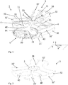
- the figure 1 represents a perspective view of an oscillator 1 according to an embodiment.
- the oscillator 1 comprises an escapement mobile 5 and a resonator 3 constituting the timebase of the oscillator.
- the resonator 3 comprises a mass element 32 held in oscillation by at least two vibrating elements 31.
- the mass element 32 comprises an anchor portion 4 configured to cooperate directly with the escapement wheel 5 so as to maintain oscillations of the first resonator 3 and to let the escapement mobile 5 move with each alternation of oscillations.
- the resonator 3 is formed of three vibrating elements 31 extending radially from a center 12 in a plane P.
- transverse "x” and longitudinal orientations will be adopted in a nonlimiting manner.
- the vibrating elements 31 are angularly spaced about 120 ° from each other.
- Each of the vibrating elements 31 is fixed at its proximal end (near the center 12) to a base 2 intended to be mounted on a plate 10 or any other fixed part of a clockwork movement or on an intermediate frame mounted itself on said watch movement.
- the distal end 35 of each of the vibrating elements 31 is fixed to the mass element 32.
- Each of the vibrating elements 31 can therefore vibrate or oscillate freely between its distal and proximal end.
- the mass element 32 is supported only by the base 2 via the vibrating element 31.
- mounting means 20 may be provided in the base 2 so as to fix the base 2 to a frame 10.
- the frame 10 may comprise a cage as illustrated in FIG. figure 12 .
- the frame 10 is intended to be mounted fixed or mobile on a watch movement (not shown).
- the base 2 is mounted directly on the watch movement, for example on a plate or a bridge.
- the frame 10 has the advantage of facilitating assembly, disassembly, adjustment and dedicated operations within the framework of the after-sales service of the oscillator 1.
- the frame 10 can take the form of a cage (as in the figure 1 ) or a capsule.
- the frame 10 can be mounted and adjusted on a part of the movement, for example the plate, in order to cooperate with the gear which it regulates.
- the escape wheel is an escape wheel 5 pivotally mounted around a shaft 54, itself mounted in a bridge 21 fixed with the base 2.
- the bridge may comprise an upper bridge 21 and a lower bridge 21 ' .
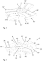
- the figure 2 shows another example of the resonator 3 in which the vibrating elements 31 are not shown.
- the base 2 extends to form the lower bridge 21 'in which the lower pivot of the shaft 54 can be mounted.
- the figure 3 shows another example in which the base 2 of the resonator 3 extends to form the lower bridge 21 'which comprises a guide stone 55 for receiving the lower pivot of the shaft 54.
- the pivots of the shaft 54 can therefore be mounted directly ( figure 2 ) or by means of a guide stone 55 ( figure 3 ).
- the bridges 21, 21 ' can therefore be seen as elements of the frame 10 which form part of the resonator 3.
- the frame can also comprise the base 2 of the resonator 3 which extends in the plane P so as to to receive the resonator 3 and one of the pivots of the shaft 54 of the escapement mobile 5.
- the frame 10 in which is mounted the oscillator 1 according to the invention can be partially integrated into the resonator 3.
- one of the pivots of the shaft 54 of the escapement mobile 5 can be mounted on the bridge 21 ', while the other pivot is held in the part of the frame 10 which will be assembled on the watch movement.
- the mass element 32 comprises three portions of the mass element 32 'also extending radially from the base 2, centered on the center 12, in plane P.
- the portions 32' are angularly spaced by approximately 120 °. each other.
- the mass element 32 is fixed to the base 2, and therefore to a fixed part of the movement when the oscillator 1 is mounted in the movement, by means of the resonator 3, here vibrating elements 31 When they oscillate, the vibrating elements 31 thus cause the mass element 32 also to oscillate.
- the three portions 32 'of the mass element 32 consist of a so-called skeletal openwork structure.
- This skeletal structure comprises a multitude of recesses 36.
- the mass, or the inertia, of the mass element 32 is therefore mainly determined by the wall 33 of the portions 32 '.
- Each of the vibrating elements 31 can be housed inside each of the portions 32 ', for example in a housing 38 formed in the wall 33 as illustrated in FIG. figure 1 .
- Each of the vibrating elements 31 comprises a vibrating blade.
- the anchor portion 4 is constituted by the arc formed between the two adjacent portions 32 'and a member 40 carried by each of the adjacent portions 32'.
- the escape wheel 5 is housed in an interior space 11 delimited by the anchor portion 4 so as to cooperate with the anchor portion 4.
- the oscillation of the vibrating elements 31 oscillates the portions 32 'and the anchor portion 4 comprising the members 40.
- the vibrating elements 31, the portions 32' and the anchor portion 4 oscillate in the same plane P around the center 12.
- the members 40 of the anchor portion 4 cooperate with the teeth 50 of the escape wheel 5 so as to maintain oscillations of the resonator 3 and to advance the escape wheel 5 of a tooth 50 at each alternation oscillations.
- the members 40 alternately receive pulses of the teeth 50 of the escape wheel 5, so as to alternately lock and release the escape wheel 5 and maintain the periodic oscillations of the resonator 3.
- the oscillator 1 thus allows the successive escape of teeth 50 in such a way that the escape wheel 5 advances in a back-and-forth movement of the anchor part 4.
- the escapement wheel 5 pivots in the same plane P as that in which oscillates the first resonator 3 and the anchor part 4.
- the figure 4 illustrates the resonator 3 according to another embodiment in which the members 40 are arranged at the ends of the portions 32 '.
- Each of the portions 32 ' comprises the members 40 so that, in this configuration, the escape wheel 5 can be mounted in one or other of the interior spaces 11 delimited by each of the anchor portions 4 between each of the two portions. 32 'adjacent.
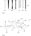
- the vibrating elements 31 of the resonator 3 may take various forms, including the shape of a beam, a vibrating blade or any other shape promoting the resonance at frequencies in a desired range of 10 Hz to 5000 Hz. , with a high quality factor, and meeting the congestion requirements required for the application.
- the vibrating elements 31 may be made to limit the stresses, particularly at their ends (proximal and distal). This can be done using distributed load beams ( figure 5b ), to multi-leaf vibrating elements ( Figures 5a and 5d ), or by modifying the local section of a beam by making local openings ( figure 5e ), drillings for example. It is also possible to lengthen the active blade length without increasing the length of the vibrating member by producing "serpentine" type structures ( figure 5c ), which makes it possible to reduce the charges in a very significant way. Finally, it is possible to reduce the risk of breaks in the recesses by softening the sharp angles, which generally represent primers of rupture or fatigue.
- a mass resonator M (expressed in g) and comprising several vibrating elements 31 formed of simple beams of stiffness k (expressed in mN.m / rad) and characterized by a height h and a thickness e
- a ratio k / M between 0.1 and 1.0 and a ratio w / e between 3 and 20 give particularly satisfactory results.
- each of the vibrating elements 31 comprises a blade having a folded portion 31 ', for example of the meander or serpentine type.
- the mass element 32 comprises two diametrically opposite portions 32 '.
- Each of the portions 32 ' comprises two vibrating elements 31 in the form of a single blade in the figure 8 and having a folded portion 31 'in the figure 9a .
- the figure 9b shows the resonator cooperating with an escape wheel 5 via two anchor part members 40.
- the escape wheel 5 is mounted in the bridge 21 integral with the resonator 3.
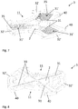
- the figure 10 shows oscillator 1 according to another embodiment wherein the mass element 32 of the resonator 3 comprises four portions 32 'angularly spaced about 90 ° from each other, each portion comprising a vibrating element 31.
- the resonator is shown cooperating with an escape wheel 5 via two anchor part members 40.
- the resonator 3 is mounted on a frame 10 comprising an upper part 14 forming a cage for the oscillator 1.
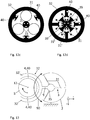
- figure 11 shows a detail of the resonator of the oscillator of the figure 10 wherein the vibrating elements 31 are not shown.
- the resonator comprises a mass element 32 has a substantially annular shape 32.
- the anchor portion 4 comprises two members 40 fixed on the mass element 32.
- the mobile (wheel) exhaust 5 is pivotally mounted in a parallel plane P 'to plane P in which oscillates the first resonator 3, below the resonator 3 in the illustrated example.
- the members 40 of the anchor portion 4 are thus arranged so as to cooperate with the teeth 50 of the escapement wheel 5 situated in the lower plane P ', for example by extending downwards, axially with respect to the element In operation, the escapement wheel 5 pivots in the parallel plane P 'to the oscillation plane P of the mass element 32a.
- the vibrating elements 31 have an arcuate shape.
- the figure 12b shows the resonator of the figure 12a comprising two pairs of vibrating elements 31, each pair comprising two vibrating elements 31 in a semicircle facing each other resulting in a cylindrical shape.
- the figure 12c shows the resonator of the figure 12a comprising three pairs of vibrating elements 31 according to the figure 12b .
- the figure 12d shows the resonator of the figure 12a in which each of the vibrating elements 31 comprises two parallel blades 31 'arranged radially.
- the resonator 3 comprises segments 39 arranged concentrically with the serge 32a but of smaller diameter than this.
- the segments 39 come to press against one of the blades 31 ', in the direction of pivoting of the resonator 3.
- the restoring force of the blade 31' pushes the segments 39 in the reverse direction, allowing oscillation of the resonator 3.
- the mass element 32 of the resonator 3 is driven in oscillation in a rotary motion, in other words, in a pivoting movement about its center 12.
- An advantage of these configurations where the resonator 3 is driven in oscillation according to a rotary movement comprises the maintenance of the differences in operation between the different positions of the oscillator 1 in the gravitational field or during shocks.
- the figure 13 represents another configuration of the oscillator 1, in which the mass element 32 comprises two portions 32 'extending generally in the same plane P in an arc of a circle with respect to a center 12.
- the escape wheel 5 is arranged in the interior space 11 delimited by the mass portions 32 ', each carrying a member 40 of the anchor portion 4.
- the escapement wheel 5 is pivotally mounted around the center 12 so that a toothing (not shown) of the escape wheel 5 comes into cooperation with the members 40.
- the escape wheel 5 is in the same plane P as the escape wheel 5, the latter being concentric with a circle inscribed by the mass portions 32 '.
- the vibrating element 31 comprises blades 31 'arranged in a star (here three blades angularly spaced by about 120 °) and fixed at a proximal end to the base 2 having the shape of a circular arc.
- the distal end 35 of the blades 31 ' is fixed to the mass element 32 via a foot 9.
- the oscillation of the blades 31' gives an oscillation movement in the plane P as indicated by the arrow 90 in fig 13.
- the superimposition of the center of gyration and the center of mass of the resonator 3 of the oscillator 1 of the figure 13 further minimizes the sensitivity of the system to the acceleration to which it could be subjected.
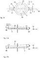
- the oscillator 1 of the invention may, however, also include a resonator where the mass element 32 is movable in oscillation in a translational motion.
- the resonator comprises a vibrating element 31 formed of two blades 31 'fixed to the base 2 at their proximal end.
- Each of the two blades 31 ' carries, at their distal end 35, a mass portion 32' comprising a member 40 of an anchor portion 4.
- An escape wheel 5 is placed between the two mass portions 32 'so as to cooperate with the members 40.
- the vibrating elements 31 oscillate from their proximal end, driving in translation in a movement back and forth the two mass portions 32 '.
- the members 40 alternately receive pulses of the teeth (not shown) of the escape wheel 5, so as to alternately lock and release the escape wheel 5 and maintain the periodic oscillations of the resonator 3.
- the efficiency of the resonator 3 can be disturbed by vibrating elements 31 resonating at different frequencies.
- the efficiency of the resonator 3 can also be disturbed by the resonance of the vibrating elements 31 which are fixed at one of their ends to the same base 2 and at the other end to the same mass element 32, and which would oscillate with different amplitudes. It is therefore advantageous for the vibrating elements 31 to resonate substantially at an amplitude (radial or transverse) which is substantially the same.
- the two mass portions 32 ' are rigidly connected, so that the blades 31' and the mass portions 32 'oscillate substantially at the same frequency and at the same amplitude.
- the vibrating elements 31 oscillating substantially at the same frequency make it possible to ensure any loss due to asynchronous movements of the one or the other of the vibrating elements 31. Thus, it is essential to obtain the best quality factor that all the vibrating members resonate at the same frequency.
- the structural modification of the material may be used locally by exposing it by irradiation with a femtosecond laser.
- the oscillator 1 of the invention is particularly intended for high frequencies ranging from 10Hz to 5'000Hz, the ideal frequency range being between 10Hz and 400Hz.
- FIGS. 15a and 15b show a bottom view of the oscillator 1 of the figure 14 , illustrating the movements in translation back and forth of the mass element 32 with each of the members 40 of the anchor portion 4 engaging with the toothing of the escape wheel 5 or disengaging it.
- the oscillator 1 comprises an escapement wheel 5 which pivots in a plane substantially perpendicular to the plane P in which oscillate the first resonator 3, the mass element 32 and anchor part 4.
- the resonator 3 comprises two blades 31 'oscillating in torsion about an axis 91 in the plane P.
- the distal end 35 of each of the blades 31' is fixed to the mass element 32 in the form of a serge.
- the members 40 of the anchor portion 4 are fixed, for example, on the inner periphery of the mass element 32.
- the escapement wheel 5 can be housed inside the mass element 32 so as to cooperate with the members 40 of the anchor portion 4.
- the vibrating element formed of the two blades 31 'and the mass element 32 oscillate like a torsion pendulum.
- the blades 31 ' may consist of double blades excited at frequencies whose modes are asymmetrical and out of the plane P.
- FIGS. 17a and 17b show a view of the oscillator 1 side of the figure 16 , illustrating the movements in oscillation about the axis 91, coincident with the axis Y, of the mass element 32 with each of the members 40 of the anchor portion 4 engaging with the toothing of the escape wheel 5 or clearing it.
- an anchor portion 4 provided with two members 40 makes it possible to leave a tooth 50 at each alternation, it is also possible to equip the anchor portion 4 with a larger number of members 40, and by varying the spacing between the members 40, so that the escape wheel 5 advances at a different speed.
- each anchor portion 4 is provided with four members 40 instead of two, distributed in such a way that only one member 40 on all four cooperates with a tooth 50 of the escape wheel 5 at each oscillation.
- Such a configuration makes it possible to obtain an advance of half a tooth alternately, ie an advance of a tooth for two alternations.
- the rotation frequency can be further reduced by the addition of more than two members 40 per anchor portion 4, 4 '.
- Oscillator 1 may be produced from a process or a combination of subtractive and / or additive microfabrication processes from a single substrate of preferably non-magnetic material or base materials combined with one another. and whose final material will preferably be non-magnetic.
- the materials chosen may be metallic or non-metallic, or a combination of both.
- the nonmagnetic metal materials include at least partially metallic materials such as metal alloys, composites comprising at least one metal as well as at least partially amorphous metal alloys.
- Nonmetallic non-magnetic materials selected include glasses (including quartz), ceramics, glass-ceramics, metalloids, such as silicon, and non-metallic composites.
- the oscillator 1 is made from a single substrate, preferably a glass, ceramic, glass-ceramic or silicon substrate, the latter being preferably chosen in the form of a wafer or under form of a substrate which lends itself to high precision and / or repeatability microfabrication operations such as DRIE or selective volume etching microfabrication, known as ISLE (In Volume Selective Etching), and which combines femtosecond laser irradiation and chemical etching, and is particularly suitable for certain families of glasses.
- a single substrate preferably a glass, ceramic, glass-ceramic or silicon substrate, the latter being preferably chosen in the form of a wafer or under form of a substrate which lends itself to high precision and / or repeatability microfabrication operations such as DRIE or selective volume etching microfabrication, known as ISLE (In Volume Selective Etching), and which combines femtosecond laser irradiation and chemical etching, and is particularly suitable for certain families of glasses.
- DRIE selective
- Non-metallic materials being more fragile, it is possible to use at least a partial overlap of the surface of the finished component with a layer of a protective material, such as diamond, which provides a protective hard layer and also has tribological properties advantageous. Diamond is used in particular for the recovery of certain silicon components.
- the frequency of the oscillator 1 can be controlled by varying the dimensions of the vibrating elements 31 and / or the dimensions of the mass element 32.
- the oscillation frequency of the different oscillation modes depends on the geometry of the oscillator 1 and can be adjusted by modifying the moment of inertia of the mass element 32. For this purpose, but also in order to modify the relationship between its inertia and its bulk, and depending on the nature of the substrate used for producing the resonator 3, it may be necessary to modify the inertia of the resonator, and more particularly of its mass element 32.
- a higher moment of inertia of the mass element 32 results in a lower oscillation frequency of the oscillator 1 and a longer oscillation time (less rapid oscillation damping).
- the moment of inertia of the mass element 32 can be modified by adding or removing weights on the mass element 32.
- weights 34 are housed in the recesses 36.
- the weight or weights 34 can be added and detached from the mass element 32 so as to be able to modify the moment of inertia of the mass element 32.
- the weight or weights 34 allow to modify the moment of inertia of the mass element 32 and therefore of the resonator 3, without substantially increasing the bulk of the oscillator 1.
- weights 34 which can be assembled by means adapted to the chosen materials and required positioning and dimensioning tolerances.
- the weights 34 can be joined to the mass element 32 by bonding, brazing, welding or bonding processes, after having covered the substrate, if necessary, with a suitable layer, or having treated its surface to optimize the accession, or even favor a partial diffusion.
- the moment of inertia of the resonator 3 by increasing the material, for example by galvanic growth, by sintering or other additive processes applicable to microcomponents, on one or more of the faces of the resonator 3 (for example, the mass element 32). It is also possible to use mechanical methods of assembly such as screwing, crimping or shoring, pinning or mounting in an elastic structure, by clamping.
- the weight 34 is advantageously manufactured in a material having a higher density than that used for the rest of the resonator 3.
- the weight 34 may be made of gold or any other metal or dense alloy.
- flyweights with a density equal to or even less than that of the resonator material, the fineness of adjustment then being improved.
- weights 34 required have the same density as that of the base material, they can be made in the same material, even in one piece, while still considering them as flyweights, insofar as their dimensioning will be chosen to fulfill the aforementioned function.
- the frequency can be increased by ablation of material on the mass element 32 and / or the flyweight 34.
- Ablation of material can be performed by machining (mechanical, laser, chemical or other), by breaking detachable elements (as for example described in the document CH656044 ) or by any other appropriate method. If detachable elements are used, they can be made during the same operation as the manufacturing operation of the resonator 3.
- the weights 34 may all have the same size and the same mass. Alternatively, to get a finer setting with a larger range, you can use weights 34 with different masses. By way of example, the weights 34 can be dimensioned into five different masses in order to correspond, respectively, to a correction of: 1 s / d, 2 s / d, 4 s / d, 8 s / d, and 16 s / day. In this way, it is possible to correct from 1 to 31 s / d by detaching a combination of appropriate elements.
- Another way of modifying the oscillation frequency of the resonator 3 is to modify the rigidity of the vibrating elements 31, preferably by modifying their quadratic moment and / or the local rigidity of the material.
- the figure 19 represents the oscillator 1 according to another embodiment.
- Oscillator 1 comprises a first resonator 3 configured in a manner similar to that illustrated in FIG. figure 14 .
- the oscillator 1 further comprises a second resonator 7.
- the second resonator 7 has no anchor portion 4 and does not cooperate with the escapement wheel (not shown in FIG. figure 19 ).
- the second resonator 7 is configured to be able to oscillate freely, that is to say, without being disturbed by the anchor portion 4 of the first resonator 3.
- the second oscillator 7 can be coupled to the oscillation of the first resonator 3 of the oscillator 1 by sympathetic resonance.
- the second oscillator 7 thus makes it possible to reduce the disturbances caused by the anchor portion 4 during the operation of the oscillator 1, for example, disturbances due to the impact of the teeth 50 of the escapement wheel 5 on the members 40 of the anchor portion 4 .
- the transmission and the coupling of the vibrations between the first resonator 3 which cooperates with the escapement wheel 5 and the second resonator 7 can be done by means of support structures (mechanical resonance), of an ambient fluid ( acoustic resonance) or by magnetic coupling.
- the surface of the regulating member 1 can be modified (for example by nano structuration) so as to increase the displaced wave pressure and thus promote the quality synchronization.
- the geometry of the oscillator 1 can be modified.
- the second free resonator 7 can be mounted under a controlled atmosphere, for example in a magnetically permeable (not shown), so as to improve the quality factor of the regulating member 1.
- the second oscillator 7 contributes to the improvement of the quality factor of the resonator 3.
- the oscillator 1 comprises an on / off mechanism 60 comprising a lever 61 actuated by the pull tab 62 of a time-setting mechanism and configured to stop and keep the oscillator 1 stopped, by stopping the vibrating elements 31 oscillator 1 in an unbalanced position, corresponding to one of the two extreme positions of the resonator 3 in normal operating mode (or an eccentric position with respect to the escape wheel 5) so as to provide a damping function. self-starting a watch movement.
- the oscillator 1 is turned on in the first oscillation mode.
- stops can be configured so as to limit the movement of the oscillator 1 along the "x", "y” and "z" axes in case significant shock.
- the self-starting function can also advantageously be facilitated by the realization of specific geometries on the members of the anchor portion 4 of the resonator and the teeth of the escapement wheel 50, the combination of which, in addition to responding to the functions exhaust required, will promote an unstable position of the oscillator, forcing a particular movement of the two elements together from the equilibrium position of the resonator when it cooperates with any organ.
- the Figures 21a and 21b show a detailed view of the teeth 50 of the escape wheel 5, according to one embodiment.
- Each of the teeth 50 of the escape wheel 5 comprises an inclined plane of impulse 51 and an inclined plane 52.
- Each of the lifts 40 also includes an inclined plane 41 but does not include a pulse plane, the top 42 of the lift 40 having rather a tip shape, the end may have a more or less pronounced round.
- the configuration of the teeth 50 of the escape wheel 5 and the lifts 40 in this embodiment allows the lifts 40 to receive the pulses of the teeth 50, and to maintain the oscillations of the resonator 3 while advancing the wheel of exhaust 5.
- the latter may be provided with elastic arms 53 so as to absorb the impacts of the lifts 40 on the teeth 50.
- Oscillator 1 may comprise thermal compensation means including compensating coatings, materials with zero thermoelastic coefficient, locally modified structure materials, and finally other means similar to those used on rockers, for example bimetallic structures, or other.
- the oscillator 1 may comprise a coating of silicon dioxide deposited on at least a portion of its surface.
- the thermal compensation means of a regulating member 1 made of silicon may be one of the means described in the document CH699780 of the plaintiff.
- the regulating member is made of a material of the family of glasses and the thermocompensation is obtained by coating based on aluminum oxide whose thermoelastic coefficient is of opposite sign to that of the substrate.
- the resonator is made of a vitreous material having a first thermoelastic coefficient and the thermocompensation is obtained by locally modifying a portion of the members, so as to give this portion a second thermoelastic coefficient compensating the first, this modification is preferably obtained by irradiation.
- the resonator 3 may be made of silicon and the thermocompensation obtained by the addition of a material having a thermoelastic coefficient of opposite sign to that of the silicon, and distributed uniformly or discontinuously at the surface and / or within the component material the vibrating elements 31.
- thermocompensation material may be silicon dioxide (SiO 2 ).
- the anchor portion 4 is secured to the mass element 32.
- the anchor portion 4 is secured to the mass element 32 by any appropriate means.
- the anchor portion 4 is made integral with the mass element 32 by bonding, welding or other means of fixing the anchor portion 4 to the mass element 32.
- the anchor portion 4 can also be integrally formed with the mass element 32, especially during the manufacture of the resonator 1.
- the resonator 3 does not require the addition of a separate anchor, advantageously to reduce the number of parts and the number of disruptive friction at each contact between the parts.
- the oscillator can to be dimensioned so as to give its escape wheel a singular rotation speed.
- the escape mobile may rotate in one second, or in integer or fractional multiples.
- the oscillator 1 may be designed in such a way that its escapement mobile 5 cooperates with its resonator 3 in several modes, in particular with a view to pairing the resonator 3 with the escapement mobile 5.
- figure 22 present for this purpose the resonator 3, similar to that of the figure 11 , equipped with three anchor parts 4, each comprising a member 40 disposed at the end of two adjacent mass portions 32 '(only one anchor portion 4 is completely visible).
- such an arrangement may comprise an anchor part 4 for an internal space 11. This arrangement makes it possible to position the resonator 3 with respect to the escapement device 5 in 3 different angular positions to make it cooperate with the most appropriate anchor part 4. to achieve the desired performance.
- figure 23 has a resonator 3 with four anchor parts 4, each anchor portion 4 being intended to cooperate with the escapement mobile 5 in four different modes.
- the escape mobile 5 itself can be sized according to several variants that make it possible to extend the pairing to more classes of oscillators.
- the figure 24 shows a sectional view of the oscillator 1, facing the plane passing through two members 40 of the anchor portion 4 cooperating with the escapement mobile 5, according to one embodiment.
- the resonator 3 comprises in its height a plurality of anchor portions 4 of different geometries, but which can cooperate with the same escapement mobile 5.
- the figure 24 representing an escape wheel having a flexible mounting plate, supported on a plurality of bearing surfaces cut in its shaft, each of these bearing surfaces carrying one or more facets or flats intended to ensure the rotational drive of the two without sliding.
- the pinion of the escapement mobile will be mounted directly on the mobile and will be fixed, while the watchmaker can suitably move the board of the escapement mobile 5 to cooperate with the anchor portion 4 appropriate.
- the escape wheel 5 can cooperate with anchor portion 4,40 which is placed outside the median plane of the resonator 3, the anchor portion 4,40 defining a first plane outside the median plane of the resonator.
- the resonator 3 then comprises a second anchor portion 4,40 for each anchor portion 4,40 placed on this first plane out of the median plane, the anchor parts 4,40 being placed inversely symmetrical (to perform the same functions when the organs do not allow reversible functions).
- the pairing is then done by reversing the mounting direction of the resonator 3 and the mobile escapement 5, the escapement mobile being advantageously mounted centered on its shaft 54.
- the resonator 3 has several anchor parts 4 which may be different (in the case of pairing) or identical.
- This latter variant has the advantage of being able to use the same resonator 3 to regulate several separate wheels, the oscillator 1 comprising in this case a plurality of escape wheels 5 each cooperating with a dedicated wheel.
- each resonator 3 and in particular the geometry of the vibrating elements 31 can be modified in different ways.
- each mass element 32 and / or each anchor portion 4 can be assimilated together as a single vibrating element or element of the oscillator.
- the members 40 of the anchor portion 4 adapted to cooperate with the teeth 50 of the escapement wheel 5 can take different forms.
- stops limit transverse movement in the plane P.
- Such stops can be oriented on an axis perpendicular to the plane of the mobile exhaust, and mounted on the frame for receiving the Oscillator 1.
- the stops can also be integrated directly into the geometry of the resonator 3, preferably to its moving part, that is to say the mass element 32 or the anchor part 4, without however excluding other solutions .
- the regulating member and the escapement of the present invention also have an unprecedented aesthetic and they can be advantageously incorporated in a watch movement of a watch in a manner to make them visible to the wearer of the watch.
- the regulating member and the exhaust can be mounted above or below the motor member of the movement.
- the escape wheel may be adapted to rotate at a speed of one revolution per minute.
Landscapes
- Physics & Mathematics (AREA)
- General Physics & Mathematics (AREA)
- Engineering & Computer Science (AREA)
- Metallurgy (AREA)
- Micromachines (AREA)
- Piezo-Electric Or Mechanical Vibrators, Or Delay Or Filter Circuits (AREA)
- Apparatuses For Generation Of Mechanical Vibrations (AREA)
Claims (35)
- Oszillator zur Regelung eines mechanischen Uhrwerks, wobei der Oszillator (1) ein Hemmungsrad (5) und einen ersten Resonator (3) aufweist; wobei der erste Resonator (3) ein Massenelement (32) aufweist;
und eine Unterlage (2), welche dazu bestimmt ist, fest oder beweglich auf das Uhrwerk montiert zu werden;
dadurch gekennzeichnet, dass
der erste Resonator (3) die Zeitbasis des Oszillators (1) bildet;
das Massenelement (32) nur durch die Unterlage (2) über mindestens zwei Schwingungselemente (31) gestützt wird, wobei die besagten mindestens zwei Schwingungselemente (31) das Massenelement (32) in Schwingung halten; und
dass das Massenelement (32) mindestens einen Ankerteil (4) aufweist, der einstückig mit dem Massenelement (32) ausgebildet ist und so konfiguriert ist, um direkt mit dem Hemmungsrad (5) zusammenzuwirken, um die Schwingungen des besagten ersten Resonator (3) aufrechtzuerhalten, und um das Hemmungsrad (5) bei jedem Schwingungswechsel bewegen zu lassen. - Oszillator gemäss Anspruch 1, worin die besagten mindestens zwei Schwingungselemente (31) im Wesentlichen dieselbe Eigenfrequenz aufweisen und/oder mit derselben Amplitude schwingen.
- Oszillator gemäss Anspruch 1 oder 2, worin die mindestens zwei Schwingungselemente (31) sich radial in einer Ebene (P) von der Unterlage (2) erstrecken, wobei mindestens ein distales Ende (35) von jedem der Schwingungselemente (31) jeweils am Massenelement (32) befestigt ist.
- Oszillator gemäss einem der vorhergehenden Ansprüche, worin der besagte mindestens eine Ankerteil (4) mindestens zwei Elemente (40) zum Zusammenwirken mit dem Hemmungsrad (5) aufweist.
- Oszillator gemäss einem der Ansprüche 1 bis 4, worin das Hemmungsrad (5) im Wesentlichen in der gleichen Ebene (P) oder in einer parallelen Ebene (P') zu derjenigen schwenkt, in welcher der erste Resonator (3) schwingt.
- Oszillator gemäss einem der Ansprüche 1 bis 4, worin das Hemmungsrad (5) in einer Ebene schwenkt, die im Wesentlichen senkrecht zur Ebene (P) ist, in welcher der erste Resonator (3) schwingt.
- Oszillator gemäss Anspruch 5 oder 6, worin das Massenelement (32) und der Ankerteil (4) um eine gleiche Achse schwingen.
- Oszillator gemäss einem der Ansprüche 1 bis 7, worin der erste Resonator (3) mindestens zwei Schwingungselemente (31) aufweist, welche sich in einer Ebene (P) aus der Unterlage (2) erstrecken; wobei ein distales Ende (35) jedes der Schwingungselemente (31) am Massenelement (32) befestigt ist.
- Oszillator gemäss Anspruch 8, worin das Massenelement (32) mindestens zwei Abschnitte (32') aufweist, welche sich radial zwischen der Unterlage (2) und dem distalen Ende (35) der Schwingungselemente (31) erstrecken.
- Oszillator gemäss dem vorhergehenden Anspruch, worin die mindestens zwei Abschnitte (32') des Massenelements (32) im Wesentlichen mit der selben Frequenz und gemäss der selben Amplitude schwingen.
- Oszillator gemäss Anspruch 9 oder 10, worin die Abschnitte (32') des Massenelements (32) starr zusammenverbunden sind.
- Oszillator gemäss einem der Ansprüche 1 bis 11, worin der Ankerteil (4) mindestens zwei Elemente (40) aufweist.
- Oszillator gemäss einem der vorhergehenden Ansprüche, worin jedes der Schwingungselemente (31) eine Vibrationsplatte oder einen Vibrationsbalken aufweist.
- Oszillator gemäss einem der Ansprüche 1 bis 13, worin jedes der Schwingungselemente (31) einen gefalteten Abschnitt (31') vom Mäander- oder Serpentinentyp aufweist.
- Oszillator gemäss einem der Ansprüche 1 bis 14, worin jedes der Schwingungselemente (31) eine bogenförmige Form aufweist.
- Oszillator gemäss einem der Ansprüche 1 bis 15, worin jedes der Schwingungselemente (31) eine zylindrische Form aufweist.
- Oszillator gemäss einem der Ansprüche 1 bis 16, worin jedes der Schwingungselemente (31) mindestens zwei parallele Klingen (31') aufweist, die radial angeordnet sind.
- Oszillator gemäss einem der vorhergehenden Ansprüche, worin der besagte mindestens eine Ankerteil (4) so konfiguriert ist, um direkt mit den Zähnen (50) des Hemmungsrads (5) zusammenzuwirken, um das besagte Hemmungsrad (5) bei jedem Schwingungswechsel schwenken zu lassen.
- Oszillator gemäss Anspruch 18, worin der Ankerteil (4) mindestens zwei Elemente (40) umfasst, welche so angeordnet sind, dass nur ein Element (40) mit einem Zahn (50) des Hemmungsrads (5) bei jeder Schwingung zusammenarbeitet, so dass das Hemmungsrad (5) bei jedem Schwingungswechsel um einen Halbzahn (50) schwenkt.
- Oszillator gemäss einem der Ansprüche 1 bis 19, worin die vibrierende Klinge einen rechteckigen Querschnitt mit einem Verhältnis der Steifheit zur Masse zwischen 0,1 und 1,0 aufweist, und dessen Verhältnis der Höhe zur Dicke zwischen 3 und 20 liegt.
- Oszillator gemäss einem der Ansprüche 1 bis 20, worin der erste Resonator (3) mit einer Frequenz zwischen 10 Hz und 5'000 Hz schwingt.
- Oszillator gemäss einem der Ansprüche 1 bis 21, worin das Massenelement (32) mindestens ein Gewichtchen (34) aufweist, welches zum Masseelement (32) hinzugefügt und von diesem gelöst werden kann, um das Trägheitsmoment des Massenelements (32) ändern zu können.
- Oszillator gemäss einem der Ansprüche 1 bis 22, ferner mit einem Rahmen (10) zur Aufnahme des Oszillators (1), und welcher dazu bestimmt ist, fest oder beweglich am Uhrwerk angebracht zu werden.
- Oszillator gemäss einem der Ansprüche 1 bis 23, worin der Resonator (3) thermokompensiert ist.
- Oszillator gemäss Anspruch 24, worin der Resonator (3) aus Silizium besteht und die Thermokompensation durch Zuführung eines Thermokompensationsmaterials mit einem thermoelastischen Koeffizienten mit entgegengesetztem Vorzeichen zu demjenigen von Silizium erhalten wird.
- Oszillator gemäss Anspruch 25, worin das Thermokompensationsmaterial Siliziumdioxid ist.
- Oszillator gemäss einem der Ansprüche 1 bis 26, worin die Oszillationsfrequenz des Oszillators (1) durch Ändern der Masse des Massenelements (32) einstellbar ist.
- Oszillator gemäss einem der Ansprüche 1 bis 27, worin der Resonator (3) in allen Positionen so ausgeglichen ist, so dass er zwischen den verschiedenen Positionen eine Laufvariation von nicht mehr als zwei Sekunden aufweist.
- Oszillator gemäss einem der Ansprüche 1 bis 28, ferner mit einem zweiten Resonator (7), der durch sympathische Resonanz mit der Schwingung des ersten Resonators (3) gekoppelt ist, und welcher mit einer Frequenz schwingt, die das Vielfache, das Gleiche oder ein Teil von derjenigen des ersten Resonators (3) ist.
- Oszillator gemäss Anspruch 29, worin die Kopplung mit der Oszillation eine magnetische Kopplung umfasst; und worin der zweite Oszillator (7) in einer kontrollierten Atmosphäre montiert wird.
- Oszillator gemäss einem der Ansprüche 1 bis 30, ferner mit einem Ein/Aus-Mechanismus, der konfiguriert ist, um den Resonator (3) in einer unausgeglichenen Position anzuhalten und zu halten, und um eine Selbststartfunktion des Oszillators (1) zu gewährleisten.
- Oszillator gemäss Anspruch 31, worin die Geometrien des Ankerteils (4) und/oder des Hemmungsrades (5) so gewählt werden, dass sie einen Selbststart ermöglichen, wenn das Rad einem Drehmoment ausgesetzt ist.
- Oszillator gemäss einem der vorhergehenden Ansprüche, worin der Resonator mehrere Sätze von Elementen umfasst, welche dazu bestimmt sind, mit mehreren Hemmungsrädern zusammenzuarbeiten.
- Uhrwerk mit mindestens einem Zahnrad, umfassend einen Oszillator (1) gemäss einem der vorhergehenden Ansprüche.
- Uhrwerk mit einem Oszillator (1) gemäss einem der vorhergehenden Ansprüche, worin der Oszillator mit mehreren Rädern zusammenwirkt, welche jeweils mit einem separaten Zahnrad zusammenwirken sollen.
Applications Claiming Priority (2)
| Application Number | Priority Date | Filing Date | Title |
|---|---|---|---|
| CH15532015 | 2015-10-23 | ||
| PCT/IB2016/056341 WO2017068538A1 (fr) | 2015-10-23 | 2016-10-21 | Oscillateur pour un mouvement horloger mécanique |
Publications (2)
| Publication Number | Publication Date |
|---|---|
| EP3365734A1 EP3365734A1 (de) | 2018-08-29 |
| EP3365734B1 true EP3365734B1 (de) | 2019-09-04 |
Family
ID=54695415
Family Applications (1)
| Application Number | Title | Priority Date | Filing Date |
|---|---|---|---|
| EP16788814.8A Active EP3365734B1 (de) | 2015-10-23 | 2016-10-21 | Oszillator für eine mechanische uhrwerksbewegung |
Country Status (4)
| Country | Link |
|---|---|
| EP (1) | EP3365734B1 (de) |
| JP (1) | JP6646743B2 (de) |
| CN (1) | CN108139712B (de) |
| WO (1) | WO2017068538A1 (de) |
Families Citing this family (8)
| Publication number | Priority date | Publication date | Assignee | Title |
|---|---|---|---|---|
| ES2698115T3 (es) | 2015-12-16 | 2019-01-31 | Sa De La Manufacture Dhorlogerie Audemars Piguet & Cie | Mecanismo de regulación de una velocidad media en un movimiento de relojería y movimiento de relojería |
| EP3285123B1 (de) * | 2016-08-15 | 2021-04-14 | Rolex Sa | Vorrichtung zum aufziehen eines uhrwerks |
| CH713137A2 (fr) * | 2016-11-16 | 2018-05-31 | Swatch Group Res & Dev Ltd | Protection d'un mécanisme résonateur à lames contre les chocs axiaux. |
| NL2020384B1 (en) * | 2018-02-06 | 2019-08-14 | Flexous Mech Ip B V | Mechanical watch oscillator |
| EP3561605B1 (de) * | 2018-04-25 | 2020-10-28 | The Swatch Group Research and Development Ltd | Uhrreglermechanismus mit über gelenke verbundenen resonatoren |
| US11454932B2 (en) | 2018-07-24 | 2022-09-27 | The Swatch Group Research And Development Ltd | Method for making a flexure bearing mechanism for a mechanical timepiece oscillator |
| CH714992A9 (fr) | 2019-01-24 | 2020-01-15 | Csem Centre Suisse Delectronique Et De Microtechnique Sa | Régulateur horloger mécanique. |
| NL2028796B1 (en) * | 2021-07-20 | 2023-01-23 | Flexous Mech Ip B V | Method of manufacturing a plurality of mechanical resonators in a manufacturing wafer |
Family Cites Families (15)
| Publication number | Priority date | Publication date | Assignee | Title |
|---|---|---|---|---|
| CH442153A (fr) * | 1965-08-13 | 1967-03-31 | Golay Bernard Sa | Mouvement d'horlogerie |
| CH464083A (fr) | 1965-12-07 | 1968-02-29 | Golay Bernard Sa | Dispositif d'échappement pour mouvement d'horlogerie |
| CH705118B1 (fr) * | 2007-12-27 | 2012-12-31 | Chopard Technologies Sa | Mouvement horloger comportant un organe réglant à fréquence d'oscillation élevée. |
| CH705276B1 (fr) * | 2007-12-28 | 2013-01-31 | Chopard Technologies Sa | Organe d'entraînement et de transmission pour un échappement à ancre, plateau et échappement en étant équipés, et pièce d'horlogerie les comportant. |
| CH699780B1 (fr) | 2008-10-22 | 2014-02-14 | Richemont Int Sa | Ressort spiral de montre autocompensé. |
| CN102971678B (zh) * | 2010-04-01 | 2015-07-22 | 劳力士有限公司 | 用于齿轮的制动装置 |
| EP2574994A1 (de) | 2011-09-29 | 2013-04-03 | Asgalium Unitec SA | Stimmgabelresonator für ein mechanisches Uhrwerk |
| CH706274B1 (fr) | 2012-03-29 | 2016-12-15 | Nivarox Far Sa | Mécanisme d'échappement horloger comprenant un mécanisme flexible monobloc pour la transmission d'impulsions entre le balancier et la roue d'échappement. |
| CN103713511B (zh) * | 2012-09-28 | 2017-06-13 | 天津海鸥表业集团有限公司 | 一种共振双摆轮机械手表的微调机构 |
| EP2874020B1 (de) * | 2013-11-15 | 2016-10-26 | Rolex Sa | Reguliersystem für Uhrwerk |
| CH708937B1 (fr) * | 2013-12-12 | 2020-03-31 | Richemont Int Sa | Elément oscillant pour mouvement horloger. |
| JP6661543B2 (ja) * | 2014-01-13 | 2020-03-11 | エコール・ポリテクニーク・フェデラル・ドゥ・ローザンヌ (ウ・ペ・エフ・エル)Ecole Polytechnique Federale De Lausanne (Epfl) | 脱進機のない、または簡易脱進機を有する一般2自由度等方性調和振動子および関連するタイムベース |
| EP2911012B1 (de) | 2014-02-20 | 2020-07-22 | CSEM Centre Suisse d'Electronique et de Microtechnique SA - Recherche et Développement | Oszillator einer Uhr |
| CH710278B1 (fr) * | 2014-10-24 | 2024-02-15 | Richemont Int Sa | Organe réglant pour un mouvement horloger mécanique. |
| EP3032351A1 (de) * | 2014-12-09 | 2016-06-15 | LVMH Swiss Manufactures SA | Uhrmechanismus, Uhrwerk und Uhr mit solch einem Mechanismus |
-
2016
- 2016-10-21 CN CN201680061666.5A patent/CN108139712B/zh active Active
- 2016-10-21 JP JP2018520460A patent/JP6646743B2/ja active Active
- 2016-10-21 WO PCT/IB2016/056341 patent/WO2017068538A1/fr active Application Filing
- 2016-10-21 EP EP16788814.8A patent/EP3365734B1/de active Active
Non-Patent Citations (1)
| Title |
|---|
| None * |
Also Published As
| Publication number | Publication date |
|---|---|
| CN108139712A (zh) | 2018-06-08 |
| WO2017068538A9 (fr) | 2017-06-08 |
| CN108139712B (zh) | 2020-10-13 |
| JP6646743B2 (ja) | 2020-02-14 |
| WO2017068538A1 (fr) | 2017-04-27 |
| JP2018531390A (ja) | 2018-10-25 |
| EP3365734A1 (de) | 2018-08-29 |
Similar Documents
| Publication | Publication Date | Title |
|---|---|---|
| EP3365734B1 (de) | Oszillator für eine mechanische uhrwerksbewegung | |
| EP3210082B1 (de) | Mechanisches uhrwerksbewegungseinstellungselement | |
| EP2596406B1 (de) | Oszillationsmechanismus mit elastischem und mobilem drehzapfen zur energieübertragung | |
| EP2115536B1 (de) | Uhrwerk | |
| EP3182213B1 (de) | Einstellmechanismus der mittleren geschwindigkeit in einem uhrwerk, und entsprechendes uhrwerk | |
| EP3182216B1 (de) | Gekoppelte oszillatoren einer uhr | |
| EP2593839B1 (de) | Uhr | |
| WO2016124436A1 (fr) | Resonateur isochrone d'horlogerie | |
| EP2802942B1 (de) | Uhr mit mehreren unruhen | |
| JP2018531390A6 (ja) | 機械時計ムーブメント用の振動子 | |
| EP3792700B1 (de) | Oszillator einer uhr mit flexiblem zapfen | |
| WO2017102917A1 (fr) | Oscillateur mécanique pour pièce d'horlogerie, mécanisme de réglage comportant cet oscillateur mécanique, et mouvement d'horlogerie | |
| WO1999064936A1 (fr) | Procede pour transmettre des impulsions d'energie mecanique d'unesource motrice a un regulateur oscillant | |
| EP3336613B1 (de) | Resonator für uhr, der zwei pendellager umfasst, die so angeordnet sind, dass sie auf derselben ebene schwingen können | |
| EP3637196B1 (de) | Mechanischer oszillator | |
| EP3572885B1 (de) | Mechanischer oszillator eines isochronen uhrwerks in jeder position | |
| CH702799A2 (fr) | Pièce d'horlogerie comportant un mouvement mécanique à haute fréquence. | |
| EP3140698B1 (de) | Stimmgabel mechanischen oszillator für uhrwerk | |
| CH720388A2 (fr) | Résonateur piézoélectrique, moteur piézoélectrique et pièce d'horlogerie | |
| EP4391347A1 (de) | Piezoelektrischer resonator mit flexibler führung, insbesondere für rotationsmotoren von uhrwerken | |
| WO2018002778A1 (fr) | Mouvement d'horlogerie mecanique | |
| CH713837B1 (fr) | Dispositif de régulation sur la base d'un oscillateur harmonique isotrope pour pièce d'horlogerie. |
Legal Events
| Date | Code | Title | Description |
|---|---|---|---|
| STAA | Information on the status of an ep patent application or granted ep patent |
Free format text: STATUS: UNKNOWN |
|
| STAA | Information on the status of an ep patent application or granted ep patent |
Free format text: STATUS: THE INTERNATIONAL PUBLICATION HAS BEEN MADE |
|
| PUAI | Public reference made under article 153(3) epc to a published international application that has entered the european phase |
Free format text: ORIGINAL CODE: 0009012 |
|
| STAA | Information on the status of an ep patent application or granted ep patent |
Free format text: STATUS: REQUEST FOR EXAMINATION WAS MADE |
|
| 17P | Request for examination filed |
Effective date: 20180327 |
|
| AK | Designated contracting states |
Kind code of ref document: A1 Designated state(s): AL AT BE BG CH CY CZ DE DK EE ES FI FR GB GR HR HU IE IS IT LI LT LU LV MC MK MT NL NO PL PT RO RS SE SI SK SM TR |
|
| AX | Request for extension of the european patent |
Extension state: BA ME |
|
| DAV | Request for validation of the european patent (deleted) | ||
| DAX | Request for extension of the european patent (deleted) | ||
| GRAP | Despatch of communication of intention to grant a patent |
Free format text: ORIGINAL CODE: EPIDOSNIGR1 |
|
| STAA | Information on the status of an ep patent application or granted ep patent |
Free format text: STATUS: GRANT OF PATENT IS INTENDED |
|
| INTG | Intention to grant announced |
Effective date: 20190318 |
|
| RAP1 | Party data changed (applicant data changed or rights of an application transferred) |
Owner name: RICHEMONT INTERNATIONAL SA |
|
| GRAS | Grant fee paid |
Free format text: ORIGINAL CODE: EPIDOSNIGR3 |
|
| GRAA | (expected) grant |
Free format text: ORIGINAL CODE: 0009210 |
|
| STAA | Information on the status of an ep patent application or granted ep patent |
Free format text: STATUS: THE PATENT HAS BEEN GRANTED |
|
| AK | Designated contracting states |
Kind code of ref document: B1 Designated state(s): AL AT BE BG CH CY CZ DE DK EE ES FI FR GB GR HR HU IE IS IT LI LT LU LV MC MK MT NL NO PL PT RO RS SE SI SK SM TR |
|
| REG | Reference to a national code |
Ref country code: GB Ref legal event code: FG4D Free format text: NOT ENGLISH |
|
| REG | Reference to a national code |
Ref country code: CH Ref legal event code: EP Ref country code: CH Ref legal event code: NV Representative=s name: P&TS SA, CH |
|
| REG | Reference to a national code |
Ref country code: AT Ref legal event code: REF Ref document number: 1176223 Country of ref document: AT Kind code of ref document: T Effective date: 20190915 |
|
| REG | Reference to a national code |
Ref country code: DE Ref legal event code: R096 Ref document number: 602016020080 Country of ref document: DE |
|
| REG | Reference to a national code |
Ref country code: IE Ref legal event code: FG4D Free format text: LANGUAGE OF EP DOCUMENT: FRENCH |
|
| REG | Reference to a national code |
Ref country code: NL Ref legal event code: FP |
|
| REG | Reference to a national code |
Ref country code: LT Ref legal event code: MG4D |
|
| PG25 | Lapsed in a contracting state [announced via postgrant information from national office to epo] |
Ref country code: SE Free format text: LAPSE BECAUSE OF FAILURE TO SUBMIT A TRANSLATION OF THE DESCRIPTION OR TO PAY THE FEE WITHIN THE PRESCRIBED TIME-LIMIT Effective date: 20190904 Ref country code: BG Free format text: LAPSE BECAUSE OF FAILURE TO SUBMIT A TRANSLATION OF THE DESCRIPTION OR TO PAY THE FEE WITHIN THE PRESCRIBED TIME-LIMIT Effective date: 20191204 Ref country code: LT Free format text: LAPSE BECAUSE OF FAILURE TO SUBMIT A TRANSLATION OF THE DESCRIPTION OR TO PAY THE FEE WITHIN THE PRESCRIBED TIME-LIMIT Effective date: 20190904 Ref country code: HR Free format text: LAPSE BECAUSE OF FAILURE TO SUBMIT A TRANSLATION OF THE DESCRIPTION OR TO PAY THE FEE WITHIN THE PRESCRIBED TIME-LIMIT Effective date: 20190904 Ref country code: FI Free format text: LAPSE BECAUSE OF FAILURE TO SUBMIT A TRANSLATION OF THE DESCRIPTION OR TO PAY THE FEE WITHIN THE PRESCRIBED TIME-LIMIT Effective date: 20190904 Ref country code: NO Free format text: LAPSE BECAUSE OF FAILURE TO SUBMIT A TRANSLATION OF THE DESCRIPTION OR TO PAY THE FEE WITHIN THE PRESCRIBED TIME-LIMIT Effective date: 20191204 |
|
| PG25 | Lapsed in a contracting state [announced via postgrant information from national office to epo] |
Ref country code: GR Free format text: LAPSE BECAUSE OF FAILURE TO SUBMIT A TRANSLATION OF THE DESCRIPTION OR TO PAY THE FEE WITHIN THE PRESCRIBED TIME-LIMIT Effective date: 20191205 Ref country code: LV Free format text: LAPSE BECAUSE OF FAILURE TO SUBMIT A TRANSLATION OF THE DESCRIPTION OR TO PAY THE FEE WITHIN THE PRESCRIBED TIME-LIMIT Effective date: 20190904 Ref country code: ES Free format text: LAPSE BECAUSE OF FAILURE TO SUBMIT A TRANSLATION OF THE DESCRIPTION OR TO PAY THE FEE WITHIN THE PRESCRIBED TIME-LIMIT Effective date: 20190904 Ref country code: RS Free format text: LAPSE BECAUSE OF FAILURE TO SUBMIT A TRANSLATION OF THE DESCRIPTION OR TO PAY THE FEE WITHIN THE PRESCRIBED TIME-LIMIT Effective date: 20190904 Ref country code: AL Free format text: LAPSE BECAUSE OF FAILURE TO SUBMIT A TRANSLATION OF THE DESCRIPTION OR TO PAY THE FEE WITHIN THE PRESCRIBED TIME-LIMIT Effective date: 20190904 |
|
| REG | Reference to a national code |
Ref country code: AT Ref legal event code: MK05 Ref document number: 1176223 Country of ref document: AT Kind code of ref document: T Effective date: 20190904 |
|
| PG25 | Lapsed in a contracting state [announced via postgrant information from national office to epo] |
Ref country code: PT Free format text: LAPSE BECAUSE OF FAILURE TO SUBMIT A TRANSLATION OF THE DESCRIPTION OR TO PAY THE FEE WITHIN THE PRESCRIBED TIME-LIMIT Effective date: 20200106 Ref country code: AT Free format text: LAPSE BECAUSE OF FAILURE TO SUBMIT A TRANSLATION OF THE DESCRIPTION OR TO PAY THE FEE WITHIN THE PRESCRIBED TIME-LIMIT Effective date: 20190904 Ref country code: EE Free format text: LAPSE BECAUSE OF FAILURE TO SUBMIT A TRANSLATION OF THE DESCRIPTION OR TO PAY THE FEE WITHIN THE PRESCRIBED TIME-LIMIT Effective date: 20190904 Ref country code: RO Free format text: LAPSE BECAUSE OF FAILURE TO SUBMIT A TRANSLATION OF THE DESCRIPTION OR TO PAY THE FEE WITHIN THE PRESCRIBED TIME-LIMIT Effective date: 20190904 Ref country code: IT Free format text: LAPSE BECAUSE OF FAILURE TO SUBMIT A TRANSLATION OF THE DESCRIPTION OR TO PAY THE FEE WITHIN THE PRESCRIBED TIME-LIMIT Effective date: 20190904 Ref country code: PL Free format text: LAPSE BECAUSE OF FAILURE TO SUBMIT A TRANSLATION OF THE DESCRIPTION OR TO PAY THE FEE WITHIN THE PRESCRIBED TIME-LIMIT Effective date: 20190904 |
|
| PG25 | Lapsed in a contracting state [announced via postgrant information from national office to epo] |
Ref country code: IS Free format text: LAPSE BECAUSE OF FAILURE TO SUBMIT A TRANSLATION OF THE DESCRIPTION OR TO PAY THE FEE WITHIN THE PRESCRIBED TIME-LIMIT Effective date: 20200224 Ref country code: SM Free format text: LAPSE BECAUSE OF FAILURE TO SUBMIT A TRANSLATION OF THE DESCRIPTION OR TO PAY THE FEE WITHIN THE PRESCRIBED TIME-LIMIT Effective date: 20190904 Ref country code: SK Free format text: LAPSE BECAUSE OF FAILURE TO SUBMIT A TRANSLATION OF THE DESCRIPTION OR TO PAY THE FEE WITHIN THE PRESCRIBED TIME-LIMIT Effective date: 20190904 Ref country code: CZ Free format text: LAPSE BECAUSE OF FAILURE TO SUBMIT A TRANSLATION OF THE DESCRIPTION OR TO PAY THE FEE WITHIN THE PRESCRIBED TIME-LIMIT Effective date: 20190904 |
|
| REG | Reference to a national code |
Ref country code: DE Ref legal event code: R097 Ref document number: 602016020080 Country of ref document: DE |
|
| PLBE | No opposition filed within time limit |
Free format text: ORIGINAL CODE: 0009261 |
|
| STAA | Information on the status of an ep patent application or granted ep patent |
Free format text: STATUS: NO OPPOSITION FILED WITHIN TIME LIMIT |
|
| PG2D | Information on lapse in contracting state deleted |
Ref country code: IS |
|
| PG25 | Lapsed in a contracting state [announced via postgrant information from national office to epo] |
Ref country code: LU Free format text: LAPSE BECAUSE OF NON-PAYMENT OF DUE FEES Effective date: 20191021 Ref country code: DK Free format text: LAPSE BECAUSE OF FAILURE TO SUBMIT A TRANSLATION OF THE DESCRIPTION OR TO PAY THE FEE WITHIN THE PRESCRIBED TIME-LIMIT Effective date: 20190904 Ref country code: IS Free format text: LAPSE BECAUSE OF FAILURE TO SUBMIT A TRANSLATION OF THE DESCRIPTION OR TO PAY THE FEE WITHIN THE PRESCRIBED TIME-LIMIT Effective date: 20200105 |
|
| 26N | No opposition filed |
Effective date: 20200605 |
|
| REG | Reference to a national code |
Ref country code: BE Ref legal event code: MM Effective date: 20191031 |
|
| PG25 | Lapsed in a contracting state [announced via postgrant information from national office to epo] |
Ref country code: BE Free format text: LAPSE BECAUSE OF NON-PAYMENT OF DUE FEES Effective date: 20191031 Ref country code: MC Free format text: LAPSE BECAUSE OF FAILURE TO SUBMIT A TRANSLATION OF THE DESCRIPTION OR TO PAY THE FEE WITHIN THE PRESCRIBED TIME-LIMIT Effective date: 20190904 Ref country code: SI Free format text: LAPSE BECAUSE OF FAILURE TO SUBMIT A TRANSLATION OF THE DESCRIPTION OR TO PAY THE FEE WITHIN THE PRESCRIBED TIME-LIMIT Effective date: 20190904 |
|
| PG25 | Lapsed in a contracting state [announced via postgrant information from national office to epo] |
Ref country code: IE Free format text: LAPSE BECAUSE OF NON-PAYMENT OF DUE FEES Effective date: 20191021 |
|
| PG25 | Lapsed in a contracting state [announced via postgrant information from national office to epo] |
Ref country code: CY Free format text: LAPSE BECAUSE OF FAILURE TO SUBMIT A TRANSLATION OF THE DESCRIPTION OR TO PAY THE FEE WITHIN THE PRESCRIBED TIME-LIMIT Effective date: 20190904 |
|
| PG25 | Lapsed in a contracting state [announced via postgrant information from national office to epo] |
Ref country code: MT Free format text: LAPSE BECAUSE OF FAILURE TO SUBMIT A TRANSLATION OF THE DESCRIPTION OR TO PAY THE FEE WITHIN THE PRESCRIBED TIME-LIMIT Effective date: 20190904 Ref country code: HU Free format text: LAPSE BECAUSE OF FAILURE TO SUBMIT A TRANSLATION OF THE DESCRIPTION OR TO PAY THE FEE WITHIN THE PRESCRIBED TIME-LIMIT; INVALID AB INITIO Effective date: 20161021 |
|
| PG25 | Lapsed in a contracting state [announced via postgrant information from national office to epo] |
Ref country code: TR Free format text: LAPSE BECAUSE OF FAILURE TO SUBMIT A TRANSLATION OF THE DESCRIPTION OR TO PAY THE FEE WITHIN THE PRESCRIBED TIME-LIMIT Effective date: 20190904 |
|
| PG25 | Lapsed in a contracting state [announced via postgrant information from national office to epo] |
Ref country code: MK Free format text: LAPSE BECAUSE OF FAILURE TO SUBMIT A TRANSLATION OF THE DESCRIPTION OR TO PAY THE FEE WITHIN THE PRESCRIBED TIME-LIMIT Effective date: 20190904 |
|
| PGFP | Annual fee paid to national office [announced via postgrant information from national office to epo] |
Ref country code: NL Payment date: 20231019 Year of fee payment: 8 |
|
| PGFP | Annual fee paid to national office [announced via postgrant information from national office to epo] |
Ref country code: GB Payment date: 20231020 Year of fee payment: 8 |
|
| PGFP | Annual fee paid to national office [announced via postgrant information from national office to epo] |
Ref country code: FR Payment date: 20231026 Year of fee payment: 8 Ref country code: DE Payment date: 20231020 Year of fee payment: 8 Ref country code: CH Payment date: 20231102 Year of fee payment: 8 |