EP3637196B1 - Mechanischer oszillator - Google Patents
Mechanischer oszillator Download PDFInfo
- Publication number
- EP3637196B1 EP3637196B1 EP19201269.8A EP19201269A EP3637196B1 EP 3637196 B1 EP3637196 B1 EP 3637196B1 EP 19201269 A EP19201269 A EP 19201269A EP 3637196 B1 EP3637196 B1 EP 3637196B1
- Authority
- EP
- European Patent Office
- Prior art keywords
- elastic
- oscillator
- frames
- elastic system
- balance
- Prior art date
- Legal status (The legal status is an assumption and is not a legal conclusion. Google has not performed a legal analysis and makes no representation as to the accuracy of the status listed.)
- Active
Links
- 230000035939 shock Effects 0.000 claims description 11
- XUIMIQQOPSSXEZ-UHFFFAOYSA-N Silicon Chemical compound [Si] XUIMIQQOPSSXEZ-UHFFFAOYSA-N 0.000 claims description 10
- 230000010355 oscillation Effects 0.000 claims description 10
- 229910052710 silicon Inorganic materials 0.000 claims description 7
- 239000010703 silicon Substances 0.000 claims description 7
- VYPSYNLAJGMNEJ-UHFFFAOYSA-N Silicium dioxide Chemical compound O=[Si]=O VYPSYNLAJGMNEJ-UHFFFAOYSA-N 0.000 claims description 4
- 229910052814 silicon oxide Inorganic materials 0.000 claims description 4
- 239000000463 material Substances 0.000 description 11
- 229940082150 encore Drugs 0.000 description 5
- 238000000034 method Methods 0.000 description 5
- 241001639412 Verres Species 0.000 description 4
- 238000004026 adhesive bonding Methods 0.000 description 4
- 238000005452 bending Methods 0.000 description 4
- 239000011521 glass Substances 0.000 description 4
- 238000004519 manufacturing process Methods 0.000 description 4
- 125000006850 spacer group Chemical group 0.000 description 4
- 238000003466 welding Methods 0.000 description 4
- 238000010276 construction Methods 0.000 description 3
- 230000002829 reductive effect Effects 0.000 description 3
- 210000002105 tongue Anatomy 0.000 description 3
- 238000010146 3D printing Methods 0.000 description 2
- 239000000654 additive Substances 0.000 description 2
- 230000000996 additive effect Effects 0.000 description 2
- PNEYBMLMFCGWSK-UHFFFAOYSA-N aluminium oxide Inorganic materials [O-2].[O-2].[O-2].[Al+3].[Al+3] PNEYBMLMFCGWSK-UHFFFAOYSA-N 0.000 description 2
- 230000000703 anti-shock Effects 0.000 description 2
- 239000000919 ceramic Substances 0.000 description 2
- 230000000295 complement effect Effects 0.000 description 2
- 238000000708 deep reactive-ion etching Methods 0.000 description 2
- 230000000694 effects Effects 0.000 description 2
- 238000005530 etching Methods 0.000 description 2
- 230000000670 limiting effect Effects 0.000 description 2
- 239000002184 metal Substances 0.000 description 2
- 229910052751 metal Inorganic materials 0.000 description 2
- 150000002739 metals Chemical class 0.000 description 2
- 230000002441 reversible effect Effects 0.000 description 2
- 238000000926 separation method Methods 0.000 description 2
- OKTJSMMVPCPJKN-UHFFFAOYSA-N Carbon Chemical compound [C] OKTJSMMVPCPJKN-UHFFFAOYSA-N 0.000 description 1
- 241001080024 Telles Species 0.000 description 1
- 239000006096 absorbing agent Substances 0.000 description 1
- 230000001154 acute effect Effects 0.000 description 1
- ORILYTVJVMAKLC-UHFFFAOYSA-N adamantane Chemical compound C1C(C2)CC3CC1CC2C3 ORILYTVJVMAKLC-UHFFFAOYSA-N 0.000 description 1
- 229910001573 adamantine Inorganic materials 0.000 description 1
- HIGRAKVNKLCVCA-UHFFFAOYSA-N alumine Chemical compound C1=CC=[Al]C=C1 HIGRAKVNKLCVCA-UHFFFAOYSA-N 0.000 description 1
- 230000015572 biosynthetic process Effects 0.000 description 1
- 229910052799 carbon Inorganic materials 0.000 description 1
- 238000003486 chemical etching Methods 0.000 description 1
- 229910052593 corundum Inorganic materials 0.000 description 1
- 239000010431 corundum Substances 0.000 description 1
- 230000007547 defect Effects 0.000 description 1
- 239000010432 diamond Substances 0.000 description 1
- 229910003460 diamond Inorganic materials 0.000 description 1
- 238000006073 displacement reaction Methods 0.000 description 1
- 238000001035 drying Methods 0.000 description 1
- 230000005489 elastic deformation Effects 0.000 description 1
- 238000005323 electroforming Methods 0.000 description 1
- 230000001747 exhibiting effect Effects 0.000 description 1
- 238000011049 filling Methods 0.000 description 1
- 230000005484 gravity Effects 0.000 description 1
- 238000009413 insulation Methods 0.000 description 1
- 238000002955 isolation Methods 0.000 description 1
- 238000003698 laser cutting Methods 0.000 description 1
- 238000001459 lithography Methods 0.000 description 1
- 230000000873 masking effect Effects 0.000 description 1
- 238000002844 melting Methods 0.000 description 1
- 230000008018 melting Effects 0.000 description 1
- 239000007769 metal material Substances 0.000 description 1
- 239000005300 metallic glass Substances 0.000 description 1
- 238000005459 micromachining Methods 0.000 description 1
- 210000003739 neck Anatomy 0.000 description 1
- 150000004767 nitrides Chemical class 0.000 description 1
- 230000003287 optical effect Effects 0.000 description 1
- 230000003071 parasitic effect Effects 0.000 description 1
- 230000036961 partial effect Effects 0.000 description 1
- 230000002093 peripheral effect Effects 0.000 description 1
- OANVFVBYPNXRLD-UHFFFAOYSA-M propyromazine bromide Chemical compound [Br-].C12=CC=CC=C2SC2=CC=CC=C2N1C(=O)C(C)[N+]1(C)CCCC1 OANVFVBYPNXRLD-UHFFFAOYSA-M 0.000 description 1
- 239000010979 ruby Substances 0.000 description 1
- 229910001750 ruby Inorganic materials 0.000 description 1
- 229910052594 sapphire Inorganic materials 0.000 description 1
- 239000010980 sapphire Substances 0.000 description 1
- 238000000110 selective laser sintering Methods 0.000 description 1
- 238000005245 sintering Methods 0.000 description 1
- 239000000126 substance Substances 0.000 description 1
- 239000000725 suspension Substances 0.000 description 1
Images


Classifications
-
- G—PHYSICS
- G04—HOROLOGY
- G04B—MECHANICALLY-DRIVEN CLOCKS OR WATCHES; MECHANICAL PARTS OF CLOCKS OR WATCHES IN GENERAL; TIME PIECES USING THE POSITION OF THE SUN, MOON OR STARS
- G04B17/00—Mechanisms for stabilising frequency
- G04B17/04—Oscillators acting by spring tension
- G04B17/045—Oscillators acting by spring tension with oscillating blade springs
-
- G—PHYSICS
- G04—HOROLOGY
- G04B—MECHANICALLY-DRIVEN CLOCKS OR WATCHES; MECHANICAL PARTS OF CLOCKS OR WATCHES IN GENERAL; TIME PIECES USING THE POSITION OF THE SUN, MOON OR STARS
- G04B17/00—Mechanisms for stabilising frequency
- G04B17/32—Component parts or constructional details, e.g. collet, stud, virole or piton
Definitions
- the present invention relates to the field of watchmaking. It relates more particularly to a mechanical oscillator without a pivot and comprising a balance suspended from the frame by means of a plurality of elastic systems.
- the document EP 2 273 323 describes an oscillator of the aforementioned type, in which a balance is suspended from a frame element by elastic systems arranged in series. These each include a pair of blades extending in a "V" between a rigid central part and an arcuate frame, and serve to provide the return torque for the balance as well as to support the latter.
- the frame In the upper level of this construction, the frame is arranged to be screwed onto a frame element such as a plate or a bridge, and the rigid central part is fixed to that of the adjacent level.
- the frame of this last level is in turn fixed to the frame of the next elastic system, which is fixed by its rigid central part to the subsequent elastic system. This sequence continues up to the balance wheel, which is fixed at its center to the rigid central part of the last elastic system.
- the aim of the invention is therefore to provide a mechanical oscillator in which the aforementioned defects are at least partially overcome.
- the invention relates to a mechanical oscillator for a timepiece comprising a suspended balance, of any shape, arranged to oscillate about a geometric axis of rotation, that is to say an axis virtual without conventional shafts and pivots.
- a plurality of elastic systems arranged in series connect said balance to an attachment member arranged to fix said oscillator directly or indirectly to a structural element that said timepiece comprises, such as a fixed frame element, a tourbillon cage. or carousel or the like.
- the elastic systems have a stiffness considered parallel to the axial direction which is sufficient to suspend and to support the balance regardless of the orientation of the system with respect to the direction of the gravity vector, and an elasticity around said axis of rotation adapted to allow the balance to oscillate in rotation.
- each elastic system comprises an even number of at least four outer frames (that is to say four, six, eight or even more) and at least two inner connecting elements.
- Each frame carries two (or even more) elastic elements (blades elastic, combinations of rigid bars and blades or collars, or the like which ensure the elasticity of the elastic element considered as a whole) each extending between said frame and one of said inner connecting elements.
- Each internal connecting element is connected to the two elastic elements carried by one of said frames, as well as to an adjacent elastic element of each of the other frames of the same elastic system located on either side of said frame considered.
- each of said elastic systems is fixed to each elastic system adjacent thereto at the level of one of its two frames (these frames being not adjacent to each other), for example by means of tenons. , pins, studs, screws, welding, gluing or the like, these means being arranged to make the frames in question mutually integral.
- each elastic system which is adjacent to only one other is fixed to this other by every other frame, and each elastic system which is located between two others is fixed on the one hand to a first of these other systems. by every other frame, and on the other hand to the other of these other systems by the other half of its frames.
- each elastic system can be better balanced than those of the prior art and, since the elastic systems are connected in series by their frames, the force thus transmitted during the oscillations is removed from the center of rotation and consequently generates a significantly less shear in the connections between elastic systems.
- each frame belonging to each intermediate elastic system (that is to say each elastic system which is not immediately adjacent to the balance or to the member of fastener) is connected to a frame of one or other of the elastic systems adjacent thereto, half of the frames of said elastic system considered being connected to every other frame of another elastic system located opposite a first side of the elastic system considered (that is to say to the first elastic system adjacent to it), the other frames contained in said elastic system considered being connected to every other frame of another elastic system located opposite the second side of the system elastic system considered (that is to say to the second elastic system adjacent thereto), said frames of the elastic system considered being connected alternately to one or other of said adjacent elastic systems, by their frames (i.e. -to say that the ca dres of the elastic system considered are linked, by an alternating succession, to the corresponding frames of the first or of the second adjacent elastic system).
- each elastic system is oriented at an angle of (360 / N) ° around said axis of rotation with respect to the adjacent elastic system, N being the number of frames that each of said elastic systems considered individually. So, for four frames per elastic system, the relative orientation angle is 90 °, for six frames 60 °, for eight frames 45 °, etc.
- each resilient element comprises a substantially rigid middle bar, a first flexible strip extending between a first end of said bar and one of said inner connecting elements, as well as a second flexible strip extending between a second end of said bar. said bar, opposite to said first end, and one of said frames.
- the smallest dimension of the section of said blades is preferably oriented perpendicular to said axis of rotation in order to provide elasticity and rigidity in the desired directions, to obtain the operation described above.
- This elastic element configuration gives it a stiffness (that is to say a relationship between the angular displacement deforming this elastic element and the torque associated with it) which is substantially constant as a function of the angle of rotation of the balance, in any case more constant than other configurations.
- the elastic elements can be formed as single blades, no middle bar being present.
- each of said internal connecting elements is connected exclusively to frames of the same elastic system by means of the corresponding elastic elements.
- no direct connection between an internal connection element of an elastic system and an internal connection element of the adjacent elastic system is present, the only connections between the elastic systems being at the level of the frames as described below. -above.
- the oscillator further comprises a rod extending axially from said balance in a direction opposite to said elastic systems, said rod being arranged to take place with play in an opening provided in a structural element of said timepiece, no contact. between the rod and the opening not being present during normal operation of the oscillator.
- the rod can thus come into contact with the walls of said opening, which limits the radial movement of the balance and reduces the probability that the elastic systems are damaged. If the opening also defines an axial stop for the rod, a shock tending to move the balance away from the elastic system can also be damped by limiting the movement of the balance in this direction.
- the oscillator further comprises a screw screwed axially into the end of said rod, the head of said screw being arranged to come into contact with a stop secured to said structural element in the event of an impact in an axial direction, in particular in the event of an impact. shock tending to bring the balance closer to the elastic systems.
- the rod In the case of an axial conc in the other direction, the rod can also abut against a corresponding axial stop. Consequently, in the event of an impact in any direction, the oscillator is protected since the movement of the balance is limited in any direction.
- the oscillator may include a circlip or a washer integral in translation with said rod and arranged to come into contact with a stop integral with said structural element, and this in the event of impact in an axial direction.
- This stopper can be rigid or flexible.
- said rod comprises a circumferential groove arranged to cooperate with a stop which said structural element carries, and this in the event of impact in an axial direction.
- this stopper can be rigid or flexible. Said groove may be machined in the rod, or may consist of a gap between two rings fixed to the latter.
- said balance is able to perform oscillations having an amplitude of at least 15 °.
- the oscillator is thus compatible with conventional escapements, such as, for example, escapements with Swiss or English lever, detent, Omega-Daniels, or similar.
- the amplitude can be at least 60 °, at least 90 °, or even more.
- each elastic system 5 has a rotational symmetry of (720 / N) °, N being the number of frames that each elastic system has.
- the mechanical oscillator can consist of two individual oscillators as described above, arranged head-to-tail and comprising a common balance.
- the latter can be composed of a single balance, or of two sub-balances integral in rotation with one another, for example by means of a rod extending substantially along the axis of rotation, by pillars connecting the serges of the two sub-balances, or the like.
- At least some of said elastic elements are made of silicon provided with a layer of silicon oxide on at least some (preferably all) of their exterior surfaces.
- This layer makes it possible to modify the thermal coefficient of the Young's modulus of the elastic elements and thus to compensate for operating errors due to the effects of temperature variations on the materials of the elastic systems and / or of the balance.
- the term “rigid” means that an element is not likely to deform substantially during normal operation of the oscillator, in at least one given direction. Without an indication of such a direction, a "rigid member” is considered to be rigid in any direction.
- the term “elastic” on the other hand means that an elastic deformation of an element is desired during said operation, also in at least one given direction, this deformation having a desired effect on the operation of the oscillator. If an element is rigid in a first direction and elastic in a second direction, this will be clearly indicated in the text. Furthermore, in order not to overload the figures, the set of reference signs does not appear on each drawing. Finally, we note that, in the absence of any other explicit indication to the contrary, the spatial relations between elements are defined by default when the oscillator is at rest, and the axial direction is determined with respect to the axis of rotation 9 .
- the figures 1 to 3 illustrate a mechanical oscillator 1 according to the invention, in assembled state.
- This oscillator 1 comprises a balance wheel 3, which provides the inertia which, in cooperation with the elasticity of a plurality of elastic systems 5, determines the frequency of oscillation of oscillator 1 when the latter is running, that is, that is, when it is put into oscillation.
- These elastic systems 5 are arranged in series so as to connect the balance 3 to an attachment member 7, the latter being arranged to be fixed directly or indirectly (for example by means of an intermediate piece) to a fixed element. of a timepiece such as a bridge, a plate or the like or a tourbillon cage.
- the balance 3 is suspended and can pivot substantially around a non-physical axis of rotation 9, that is to say around a virtual, geometric axis and not around a shaft mounted between bearings. conventional.
- Oscillator 1 is thus devoid of pivots, which reduces friction and improves its quality factor compared to a conventional balance-spring oscillator.
- the balance 3 of the illustrated embodiment which is shown in isolation on the figure 4 , is formed of a substantially rigid frame defining a peripheral rim 3a as well as a central hub 3b, these two elements being interconnected by a plurality of arms 3c. Additional arms 3d extend cantilevered from the hub 3b in the direction of the rim 3a.
- the rim 3a as well as the additional arms 3d carry masses 3f, determining the inertia of the balance 3.
- the resonant frequency of the oscillator 1 can be adjusted in a known manner.
- the rigidity of the elastic elements 5b for example by removing material by via a laser
- the hub 3b carries a 3g chainring (see figure 3 ) fixed in the central opening of the hub 3b by means of an intermediate piece 3j (see figure 12 ) and carries a rod 3k extending axially in the direction opposite to the elastic systems 5. The operation of this rod 3k will be described below in the context of the figure 12 .
- the 3g plate has a 3h dowel as well as a 3i anti-overturn system in accordance with those in the document EP 3,037,894 .
- the balance 3 as well as the plate 3g can take any known shapes, adapted to cooperate with an escapement of any kind, such as for example an English or Swiss lever escapement, a detent escapement, an escapement. Omega-Daniels or similar exhaust.
- the serge 3a the latter can be complete, split, or partial (for example by having only two sections in the form of a bar or in an arc of a circle as in the document EP 2 273 323 above).
- the balance 3 is connected to the attachment member 7 by means of a plurality of elastic systems 5, arranged in series.
- the oscillator 1 comprises four of these systems 5, but the number may vary, for example between two and eight or even more.
- the figure 5 illustrates one of these elastic systems 5 in insulation.
- the latter comprises four rigid frames 5a, each in an arc of a circle. These frames are each connected by means of a pair of elastic elements 5b to internal connecting members 5c, said elastic elements 5b fixed to each individual frame 5a forming an acute angle between them preferably between 45 ° and 75 °, more preferably between 50 ° and 70 °.
- the four frames 5a are substantially identical and extend over the same angle, and the elastic system 5 has a rotational symmetry of 180 °. In this way, the angle formed between the elements elastics 5b of each frame 5a is also substantially identical. However, it is possible to vary these angles, for example by opposing pairs of frames.
- the extension of each elastic element 5 preferably intersects the axis of rotation 9 when the oscillator is at rest.
- the elastic elements 5b of the illustrated embodiment each consist of a rigid median bar 5d as well as a pair of elastic blades 5f extending on either side between the rigid bar and, on the one hand, the one of the frames 5a, on the other hand an internal connecting element 5c.
- the elastic elements 5b are arranged to have bending elasticity in the plane of the elastic system 5, as well as to be substantially rigid in bending perpendicular to said plane.
- the stiffness of the elastic element 5b perpendicular to said plane is at least ten times, preferably at least one hundred times, that in said plane, the smallest dimension of each blade 5f being in this plane and therefore perpendicular to the plane.
- 'axis of rotation 9 This form of elastic element 5b has an angular stiffness which is substantially constant as a function of the angle of rotation of the balance, that is to say that its elasticity coefficient remains substantially invariant during oscillations.
- the elastic elements 5b can each take the form of a single blade, as is the case in the document EP 2 273 323 , or can take the form of any type of equivalent bending element such as, for example, arrangements of necks located on either side of the rigid bar 5d. It is also not necessary for the elastic elements 5b to be straight: in fact, they can take a large number of ad hoc shapes according to the needs of those skilled in the art, in particular curved.
- the internal connecting members 5c are separated from each other by a slot 5g and are each fixed to four adjacent elastic elements 5b, of which the two in the middle are associated with one of the frames 5a, and the other two belong to each to an adjacent 5a frame corresponding, these last frames 5a being located on either side of the first frame 5a mentioned.
- a first of the internal connecting members 5c is integral with a single elastic element 5b belonging to the frame A, the two elastic elements 5b of the frame B, as well as only one of the elastic elements 5b of the frame C, according to this sequence.
- the other internal connecting member 5c is secured to the other elastic element 5b of the frame C, to the two elastic elements 5b of the frame D, as well as to the other elastic element 5b of the frame A.
- each elastic system 5 as illustrated comprises four frames 5a each associated with two elastic elements 5b, one can also provide six or even eight, which will increase the number of internal connecting elements 5c to three or four respectively, each remaining inner connecting element 5c associated with four adjacent elastic elements 5b as described above.
- the rotational symmetry of each elastic system 5 is (720 / N) °, where N is the number of frames 5a per elastic system 5.
- the elastic systems 5 are connected in series between the balance 3 and the attachment member 7, as explained in detail below.
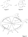
- the balance 3 side On the balance 3 side, the latter is fixed to two opposing frames 5a of a first elastic system 5 by means of tenons 11 (see in particular figure 6 ) which ensure not only the fixing of these components relative to each other, but also a predetermined separation between the balance 3 and the elastic system 5.
- tenons 11 can take various forms, of which two different and non-limiting examples are illustrated on the figures 7 and 8 , but it is also possible to fix the frames 5a to each other by means of any spacers, regardless of the additional parts, or the parts integrally with the frames 5a.
- the figure 7 illustrates a first tenon 11 which can in particular be manufactured from a plate of micromachinable material such as silicon.
- the tenon 11 comprises two heads 11a extending in two opposite directions, and separated by a spacer 11b of rectangular section, and can be formed by etching (laser, chemical (for example DRIE), by dry process. .), electroforming (for example LIGA or other), by an additive process (3D printing), or any other similar process.
- the heads 11a are arranged to be fixed in corresponding openings having complementary shapes provided in the elements to be connected by driving, gluing, welding, clipping or the like.
- the spacer 11b serves to define a predetermined separation between the two elements thus fixed to one another, so that the frames 5a, the elastic elements 5b and the internal connecting elements 5c do not come into contact.
- the figure 8 illustrates a conventional tenon 11, of circular section, which can be machined in a conventional manner and which does not need to be described in detail.
- its heads 11a as well as its spacer 11b fulfill the same functions as those of the tenon 11 of the figure 7 .
- Tenons 11 of this shape can also be fixed in the complementary openings by means of driving, gluing, welding, clipping or the like.
- the tenons 11 can be integral with some of the frames 5a.
- the figure 9 illustrates the attachment member 7, which is intended to be attached to a fixed structural element of a timepiece, such as for example a bridge or a plate, or else to a movable structural element such as a watchcage. whirlpool or carousel or the like.
- this attachment member comprises a pair of tongues 7a provided with a plurality of openings intended to receive pins of positioning, fixing screws, screw feet or the like, as well as a rigid ring 7b.
- other forms of attachment members are possible.
- two of the frames 5a of the last elastic system 5 can themselves act as fastening members, by being fixed directly or indirectly to a structural element of the movement, or by being integrated into this. structural element.
- the figure 10 illustrates oscillator 1 in exploded view in order to illustrate more clearly the series arrangement of the various elastic systems 5.
- level of the attachment member has been indicated as "level 1", that immediately adjacent to the balance wheel as "level 4", and the sequence of intermediate levels has been numbered as indicated in the figure.
- suffixes A, B, C, D have been used to identify specific frames, following the corresponding indications in the figure 5 .
- the elastic system 5 of level 1 which, as a reminder, is integral with the attachment member at the level of the frames 5aB and 5aD.
- the other two frames 5aA and 5aC which are free to move in their plane relative to the attachment member 7a, are attached to the two adjacent frames 5aB and 5aD of the next elastic system 5, via the aforementioned tenons 11.
- This last elastic system 5 is oriented at 90 ° with respect to that integrated into the fastening member and this when the oscillator 1 is at rest, so that the slots 5g between the internal connecting members 5c of each level orientates at 90 ° to each other.
- the other two frames 5aA and 5aC of level 2 are in turn fixed by means of tenons 11 to the two adjacent frames 5aB and 5aD of the next elastic system 5 of level 3, the other two frames 5aA and 5aC of this level being fixed in turn to frames 5aB and 5aD respectively of level 4. Finally, the other frames 5aA and 5aC of level 4 are attached to the balance 3. Note that the elastic systems 5 of levels 2 and 3 are considered to be elastic systems 5 intermediaries, since each of these elastic systems 5 is adjacent to two others located on either side in the axial direction.
- the figure 11 illustrates more clearly the relative orientation of two adjacent levels of elastic systems 5, in particular levels 4 and 3.
- the orientation of this view is the reverse of that of the figure 10 , and for this reason level 4 is above level 3 in this figure. It is clearly seen how the slots between the internal connecting members 5c of each adjacent level are oriented at 90 ° with respect to each other, since the two elastic systems 5 are oriented at 90 ° with respect to each other. 'other.
- each elastic system comprises six frames 5a (and thus three internal connecting members 5c)
- the angular relationship between each elastic system 5 and the adjacent elastic systems 5 is 60 °.
- the angular relationship is 45 °, the same considerations also apply.
- the angular relationship between adjacent elastic systems is at the rate of (360 / N) °, thanks to the rotational symmetry of (720 / N) ° of each elastic system 5.
- the number of elastic systems 5 is four, but the number can vary between two and eight or even more.
- the arrangement of four elastic systems 5 allows an amplitude of about 100 ° to 120 ° for the oscillations of the balance 3, a lower number of elastic systems 5 generating oscillations of smaller amplitude, a higher number causing oscillations of greater amplitude.
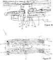
- the figure 12 illustrates, in isometric view, the oscillator 1 described above, mounted on a bridge 11 integral with a plate 13 of a clockwork movement.
- This plate 13 also carries a finishing gear 15 and an escapement 17 in a known manner.
- the free end of the cylindrical rod 3k takes place in an opening 19a provided in a ring 19 fixed in the plate 13 by driving, gluing, welding or the like.
- this opening can be formed directly in the plate 13.
- the opening 19a can be blind or through, and in the illustrated embodiment it is through but has a shoulder 19c against which the end of the rod 3k can abut in case of axial shock tending to move the balance 3 away from the elastic systems 5.
- the ring 19 (or the aforementioned opening formed directly in a structural element) can be provided in a bridge, an element a tourbillon or carousel cage, or any other structural element, whether fixed or mobile. This also applies for the other variants described below.
- the figure 13 illustrates a variation of a shock-absorbing arrangement which differs from that of the figure 12 in that a screw 3p is screwed axially into the free end of the rod 3k, the screw not coming into contact with the walls of the opening 19a during normal operation of the oscillator 1.
- the opening 19a in the ring 19 defines a shoulder 19c against which the head of the screw 3p abuts in the event of an axial impact tending to bring the balance 3 of the elastic systems 5.
- neither the rod 3k , nor the screw 3p comes into contact with any surface of the opening 19a or of the shoulder.
- the movement of the oscillator is thus limited in the event of an impact along any axis of translation or of rotation, with the exception of the axis of rotation 9 of oscillator 1.
- the figure 14 further illustrates a variant of an anti-shock arrangement, in which the rod 3k is provided with a circlip 3m which is fixed at a suitable location, for example by clipping.
- a circlip instead of a circlip, one can use a chased, glued, welded or similar washer on the rod 3k.
- the axial movement of the balance 3 is limited on the one hand by the outer surface of the ring 19 which is opposite the balance 3, and on the other hand by a stop element 21 which is integral with a frame element and whose end 21a is superimposed on the circlip 3m.
- This stop element can take any shape, but can be for example a rocker mounted on the frame element.
- This rocker can for example pivot around a pin in an angular range determined by an eccentric or by other positioning means (such as for example two opposing screws), a locking device such as one or more screws or the like being able to be arranged to block the rocker in pivoting.
- the opening 19a in the ring 19 is cylindrical in the illustrated variant, but nothing prevents the use of a ring 19 like that of the figure 12 the opening 19a of which is partially closed by a shoulder 19c.
- the rod 3k abuts against the inner wall of the opening 19a, and during an axial impact, the circlip 3m abuts against one or the other of the surface of the ring 19 or the end 21a of the stop element 21.
- the figure 15 illustrates yet another variant of an anti-shock arrangement, where the rod 3k has a circumferential groove 3n in which the end of a stop element 21 fixed to a frame element 13 takes place.
- the end 21a of the stop element 21 passes through a lateral opening 19b made in the ring 19. If the stop element stopper 21 has a certain elasticity in bending, the stopper element 21 can serve as a shock absorber. In the event of a strong axial impact, which is sufficient to cause the stop element to bend, the latter comes into contact with one or the other of the walls of said opening 19b which are located opposite the stop element 21 in order to limit the movement of the balance 3.
- the figure 16 further illustrates a variant of a shock-absorbing arrangement, which differs from that of the figure 15 in that, instead of a groove 3n machined in the body of the rod 3k, two rings 3o, 3p are driven out, glued or welded to the rod 3k. These two rings 3o, 3p are separated from one another by an annular gap, which constitutes said groove 3n in which the end 21a of the stop element 21 takes place.
- the diameter of the end of the rod 3k is reduced, but it is also possible that it has the same diameter at each ring 3o, 3p.
- the oscillator 1 has been illustrated attached to a fixed frame element of a clockwork movement. However, it can alternatively be fixed to a movable structural element, such as a tourbillon or carousel cage, or to a bridge fixed in turn to such a cage.
- a movable structural element such as a tourbillon or carousel cage
- the fixing member 7, the elastic systems 5 as well as the frame 3a of the balance 3 are particularly suitable for manufacture by micromachining, on the basis of a non-metallic material.
- manufacturing processes by masking and etching (wet or dry) of material plates (such as the DRIE process), laser cutting of such plates and the like.
- Microstructuring processes are also possible, by modifying the structure of material plates, for example by laser irradiation (in particular by “femtolaser”) and then removing the irradiated material by chemical etching.
- laser irradiation in particular by “femtolaser”
- chemical etching we could even create a one-piece oscillator by applying the latter process to a block of photostructurable material such as suitable glass.
- Additive manufacturing processes based on 3D printing stereolithography, selective laser sintering, selective laser melting, etc.
- 3D printing stereolithography, selective laser sintering, selective laser melting, etc.
- LIGA Lithography, Galvanoformung, Abformung
- sintering and the like are also possible.
- these materials can also be coated, for example with silicon oxide, adamantine carbon (DLC), alumina or the like, in order to modify their mechanical, thermal or optical properties, in a known manner.
- an outer layer of silicon oxide can be advantageously formed on a silicon core in order to make the operation of the oscillator 1 substantially independent of the temperature by modifying the thermal coefficient of the modulus of Young of elastic elements 5b. Indeed, by varying the thickness of this layer, said thermal coefficient of the Young's modulus of the elastic elements can be made substantially zero, or can be made the inverse of that of silicon in order to compensate for the variations in rate generated by the thermal expansion of the balance.
- FIG 17 illustrates yet another variant of a mechanical oscillator 1 according to the invention, which comprises two oscillators 1 as described above arranged head-to-tail and comprising a common balance 3. These two sub-oscillators are thus coupled at the level of the balance 3, and the assembly can alternatively be considered as a system of oscillators.
- this variant comprises two oscillators 1 as illustrated in the figures 1 to 11 mounted in reverse orientations, their individual balances 3 being adjacent and made integral in rotation with one another in order to form a common balance which is linked at the same time to each attachment member 7 by means of a corresponding elastic system 5.
- the individual balances associated with each elastic system 5 are considered as “sub-balances”, their whole constituting the common balance 3.
- each elastic system 5 is identical, and the tongues 7a of each attachment member 7 extend in the same direction.
- the two elastic systems 5 may be different, and the tongues 7a may extend in different directions.
- the two individual balances, or even sub-balances are made integral in rotation with one another by means of a rod 3k which extends substantially along the geometric axis of rotation 9, and is driven, glued, welded or similar to each sub-balance.
- a rod 3k which extends substantially along the geometric axis of rotation 9
- pillars or the like extending between the struts or among other parts of the pendulums are also foreseeable.
- a single individual balance wheel is also possible as a common balance wheel.
- This arrangement has greater stiffness in translation, in particular along the axis 9, as well as in torsion, in particular around any axis that is not the axis of rotation 9. The movement of the balance 3 in the event of an impact is thus reduced, regardless of a translational or rotational shock.
- each elastic system 5 be planar, more complex shapes also being possible.
- the various frames 5a must not be absolutely all identical in shape.
Landscapes
- Physics & Mathematics (AREA)
- General Physics & Mathematics (AREA)
- Micromachines (AREA)
- Apparatuses For Generation Of Mechanical Vibrations (AREA)
- Springs (AREA)
Claims (17)
- Mechanischer Oszillator (1) für eine Uhr, umfassend:• eine aufgehängte Unruh (3), die dazu angeordnet ist, um eine geometrische Drehachse (9) zu schwingen,• eine Mehrzahl von elastischen Systemen (5), die in Reihe angeordnet sind und die Unruh (9) mit einem Anbringungsteil (7) verbinden, das angeordnet ist, den Oszillator (1) an einem Strukturelement (11) zu befestigen, das die Uhr aufweist;dadurch gekennzeichnet, dass jedes elastische System (5) eine gerade Anzahl von mindestens vier Außenrahmen (5a) und mindestens zwei inneren Verbindungselementen (5c) aufweist, wobei jeder Rahmen (5a) zwei elastische Elemente (5b) trägt, die sich jeweils zwischen dem Rahmen (5a) und einem der inneren Verbindungselemente (5c) erstrecken,
dadurch, dass jedes innere Verbindungselement (5c) mit den zwei elastischen Elementen (5b), die von einem der Rahmen (5a) getragen werden, sowie mit einem angrenzenden elastischen Element (5b) jedes der Rahmen (5a) desselben elastischen Systems (5), das sich beiderseits des einen Rahmens (5a) befindet, verbunden ist;
und dadurch, dass jedes der elastischen Systeme (5) an jedem elastischen System (5), das daran angrenzt, mittels eines von zwei seiner Rahmen (5a) befestigt ist, wobei diese Rahmen (5a) nicht aneinander angrenzen. - Oszillator (1) nach Anspruch 1, wobei:• die Unruh (3) mit einem Rahmen (5a) von zwei des elastischen Systems (5) verbunden ist, das daran angrenzt, wobei diese Rahmen (5a) nicht aneinander angrenzen;• das Anbringungsteil (7) mit einem Rahmen (5a) von zwei des elastischen Systems (5) verbunden ist, das daran angrenzt, wobei diese Rahmen (5a) nicht aneinander angrenzen.
- Oszillator (1) nach Anspruch 2, wobei der Oszillator mindestens drei der elastischen Systeme (5) umfasst, wobei jeder Rahmen (5a), der zu jedem dazwischen liegenden elastischen System (5) gehört, mit einem Rahmen (5a) des einen oder anderen der elastischen Systeme (5) verbunden ist, die daran angrenzen, wobei ein Rahmen (5a) von zwei des betrachteten elastischen Systems mit einem Rahmen (5a) von zwei eines anderen elastischen Systems (5) verbunden sind, das sich auf einer ersten Seite des betrachteten elastischen Systems (5) befindet, wobei die anderen Rahmen (5a), die das betrachtete elastische System (5) aufweist, mit einem Rahmen (5a) von zwei eines anderen elastischen Systems (5) verbunden sind, das sich auf der zweiten Seite des betrachteten elastischen Systems (5) befindet, wobei die Rahmen (5a) des betrachteten elastischen Systems (5) abwechselnd mit dem einen oder anderen der angrenzenden elastischen Systeme (5) verbunden sind.
- Oszillator (1) nach einem der vorhergehenden Ansprüche, wobei jedes elastische System (5) im Verhältnis zum elastischen System (5), das daran angrenzt, um einen Winkel von (360/N)° um die Drehachse (9) orientiert ist, wobei N die Anzahl von Rahmen ist, die jedes elastische System (5) aufweist.
- Oszillator (1) nach einem der vorhergehenden Ansprüche, wobei jedes elastische Element (5b) Folgendes aufweist:• eine Mittelstange;• eine erste flexible Klinge (5f), die sich zwischen einem ersten Ende der Stange und einem der inneren Verbindungselemente (5c) erstreckt, und• eine zweite flexible Klinge (5f), die sich zwischen einem zweiten Ende der Stange, das dem ersten Ende gegenüberliegt, und einem der Rahmen (5a) erstreckt.
- Oszillator (1) nach einem der vorhergehenden Ansprüche, wobei jedes der inneren Verbindungselemente (5c) mittels entsprechender elastischer Elemente (5b) ausschließlich mit Rahmen (5a) desselben elastischen Systems verbunden ist.
- Oszillator (1) nach einem der vorhergehenden Ansprüche, ferner umfassend einen Stift (3k), der sich axial von der Unruh (3) in einer Richtung erstreckt, die den elastischen Systemen (5) entgegengesetzt ist, wobei der Stift (3k) angeordnet ist, sich mit einem Spiel in eine Öffnung (19a) einzufügen, die in einem Strukturelement (13) der Uhr vorgesehen ist.
- Oszillator (1) nach Anspruch 7, umfassend eine Schraube (3p), die axial in das Ende des Stifts (3k) geschraubt ist, wobei der Kopf der Schraube (3b) angeordnet ist, im Falle eines Stoßes in einer axialen Richtung mit einem Anschlag (19c) in Kontakt zu treten, der mit dem Strukturelement (13) fest verbunden ist.
- Oszillator (1) nach Anspruch 7, umfassend einen Sicherungsring (3m) oder eine Scheibe, der/die mit dem Stift (3k) translatorisch fest verbunden ist und angeordnet ist, im Falle eines Stoßes in einer axialen Richtung mit einem Anschlag (21a, 19) in Kontakt zu treten, der mit dem Strukturelement (13) fest verbunden ist.
- Oszillator (1) nach Anspruch 7, wobei der Stift (3k) eine Umfangsrille (3n) aufweist, die angeordnet ist, im Falle eines Stoßes in einer axialen Richtung mit einem Anschlag (21a) zusammenzuwirken, der mit dem Strukturelement (13) fest verbunden ist.
- Oszillator (1) nach Anspruch 10, wobei die Umfangsrille (3n) von einem Zwischenraum gebildet ist, der zwischen zwei Ringen (3o, 3p) gebildet ist, die an dem Stift (3k) befestigt sind.
- Oszillator (1) nach einem der vorhergehenden Ansprüche, der so angeordnet ist, dass die Unruh (3) Schwingungen mit einer Amplitude von mindestens 15°, vorzugsweise mindestens 30°, vorzugsweise mindestens 60°, vorzugsweise mindestens 90° durchführt.
- Oszillator (1) nach einem der vorhergehenden Ansprüche, wobei jedes elastische System 5 eine Drehsymmetrie von (720/N)° aufweist, wobei N die Anzahl von Rahmen ist, die jedes elastische System (5) aufweist.
- Mechanischer Oszillator (1) umfassend zwei Oszillatoren (1) nach einem der Ansprüche 1 bis 6, die entgegengesetzt angeordnet sind und eine gemeinsame Unruh aufweisen.
- Mechanischer Oszillator (1) nach Anspruch 16, wobei sich die gemeinsame Unruh aus zwei Unter-Unruhen zusammensetzt, die zueinander drehfest sind.
- Oszillator (1) nach einem der vorhergehenden Ansprüche, wobei wenigstens bestimmter der elastischen Elemente (5b) aus Silizium hergestellt sind, versehen mit einer Siliziumoxidschicht auf wenigstens bestimmter ihrer Flächen.
- Uhrwerk umfassend einen Oszillator (1) nach einem der vorhergehenden Ansprüche.
Applications Claiming Priority (1)
| Application Number | Priority Date | Filing Date | Title |
|---|---|---|---|
| CH01228/18A CH715438A1 (fr) | 2018-10-08 | 2018-10-08 | Oscillateur mécanique et mouvement horloger le comprenant. |
Publications (2)
| Publication Number | Publication Date |
|---|---|
| EP3637196A1 EP3637196A1 (de) | 2020-04-15 |
| EP3637196B1 true EP3637196B1 (de) | 2021-05-19 |
Family
ID=64332251
Family Applications (1)
| Application Number | Title | Priority Date | Filing Date |
|---|---|---|---|
| EP19201269.8A Active EP3637196B1 (de) | 2018-10-08 | 2019-10-03 | Mechanischer oszillator |
Country Status (2)
| Country | Link |
|---|---|
| EP (1) | EP3637196B1 (de) |
| CH (1) | CH715438A1 (de) |
Families Citing this family (1)
| Publication number | Priority date | Publication date | Assignee | Title |
|---|---|---|---|---|
| EP4202567A1 (de) | 2021-12-22 | 2023-06-28 | Montres Breguet S.A. | Anordnung von entgegengesetzten flexiblen führungen für ein uhrwerk, insbesondere für eine anzeigevorrichtung |
Family Cites Families (7)
| Publication number | Priority date | Publication date | Assignee | Title |
|---|---|---|---|---|
| DE602007013123D1 (de) | 2007-11-28 | 2011-04-21 | Manuf Et Fabrique De Montres Et De Chronometres Ulysse Nardin Le Locle S A | Mechanischer oszillator mit einem optimierten thermoelastischen koeffizienten |
| CH701421B1 (fr) | 2009-07-10 | 2014-11-28 | Manuf Et Fabrique De Montres Et Chronomètres Ulysse Nardin Le Locle Sa | Oscillateur mécanique. |
| EP2975469B1 (de) * | 2014-07-14 | 2017-07-05 | Nivarox-FAR S.A. | Biegsamer Führungsdraht für Uhrwerke |
| EP3037894B1 (de) | 2014-12-22 | 2018-01-31 | Manufacture et fabrique de montres et chronomètres Ulysse Nardin Le Locle SA | Mechanismus und Verfahren zur Geschwindigkeitseinstellung in einem Uhrwerk |
| CH710759A2 (fr) * | 2015-02-20 | 2016-08-31 | Nivarox Far Sa | Oscillateur pour une pièce d'horlogerie. |
| EP3147725B1 (de) * | 2015-09-28 | 2018-04-04 | Nivarox-FAR S.A. | Oszillator mit rotierendem gesperr |
| EP3299905B1 (de) * | 2016-09-27 | 2020-01-08 | CSEM Centre Suisse d'Electronique et de Microtechnique SA - Recherche et Développement | Mechanischer oszillator für ein uhrwerk |
-
2018
- 2018-10-08 CH CH01228/18A patent/CH715438A1/fr not_active Application Discontinuation
-
2019
- 2019-10-03 EP EP19201269.8A patent/EP3637196B1/de active Active
Non-Patent Citations (1)
| Title |
|---|
| None * |
Also Published As
| Publication number | Publication date |
|---|---|
| EP3637196A1 (de) | 2020-04-15 |
| CH715438A1 (fr) | 2020-04-15 |
Similar Documents
| Publication | Publication Date | Title |
|---|---|---|
| EP3355130B1 (de) | Resonatormechanismus eines uhrwerks | |
| EP3293584B1 (de) | Oszillatormechanismus für uhr | |
| EP3035127B1 (de) | Stimmgabeloszillator einer stimmgabelgesteuerten Uhr | |
| EP2761380B1 (de) | Einteilige anordnung aus einer spiralfeder und spannzange | |
| EP3548973B1 (de) | Vorrichtung für uhren, uhrmechanismus und uhr mit einer solchen vorrichtung. | |
| EP2273323B1 (de) | Mechanischer Oszillator | |
| EP2596406B1 (de) | Oszillationsmechanismus mit elastischem und mobilem drehzapfen zur energieübertragung | |
| EP3365734B1 (de) | Oszillator für eine mechanische uhrwerksbewegung | |
| CH709291A2 (fr) | Oscillateur de pièce d'horlogerie. | |
| EP3382472A1 (de) | Führungslager einer unruhwelle einer uhr | |
| EP2206022B1 (de) | Stossdämpfende lagerung für eine uhr | |
| EP3667432B1 (de) | Uhrresonator, der mindestens eine flexible führung umfasst | |
| EP2690506B1 (de) | Antischwingungsspirale für Uhr | |
| EP2690507A1 (de) | Spiralfeder einer Uhr | |
| EP2908183B1 (de) | Spiralfeder einer Uhr | |
| EP3637196B1 (de) | Mechanischer oszillator | |
| EP2790066A2 (de) | Kassette für Uhrwerksmechanismus | |
| EP3792700A1 (de) | Oszillator einer uhr mit flexiblem zapfen | |
| EP3438762A2 (de) | Uhrwerkoszillator mit flexiblen führungen mit grosser winkelförmiger laufbahn | |
| EP3273309B1 (de) | Hybridoszillator einer uhr | |
| EP3435172B1 (de) | Herstellungsverfahren eines flexiblen führungsmechanismus für mechanischen oszillator eines uhrwerks | |
| EP3276431B1 (de) | Mechanischer oszillator für uhrwerk | |
| CH714030A2 (fr) | Oscillateur d'horlogerie à guidages flexibles à grande course angulaire. | |
| EP3839651B1 (de) | Mechanischer oszillator einer uhr mit flexibler führung | |
| EP3451073B1 (de) | Uhrwerkoszillator mit flexiblen führungen mit grosser winkelförmiger laufbahn |
Legal Events
| Date | Code | Title | Description |
|---|---|---|---|
| PUAI | Public reference made under article 153(3) epc to a published international application that has entered the european phase |
Free format text: ORIGINAL CODE: 0009012 |
|
| STAA | Information on the status of an ep patent application or granted ep patent |
Free format text: STATUS: THE APPLICATION HAS BEEN PUBLISHED |
|
| AK | Designated contracting states |
Kind code of ref document: A1 Designated state(s): AL AT BE BG CH CY CZ DE DK EE ES FI FR GB GR HR HU IE IS IT LI LT LU LV MC MK MT NL NO PL PT RO RS SE SI SK SM TR |
|
| AX | Request for extension of the european patent |
Extension state: BA ME |
|
| STAA | Information on the status of an ep patent application or granted ep patent |
Free format text: STATUS: REQUEST FOR EXAMINATION WAS MADE |
|
| 17P | Request for examination filed |
Effective date: 20201008 |
|
| RBV | Designated contracting states (corrected) |
Designated state(s): AL AT BE BG CH CY CZ DE DK EE ES FI FR GB GR HR HU IE IS IT LI LT LU LV MC MK MT NL NO PL PT RO RS SE SI SK SM TR |
|
| GRAP | Despatch of communication of intention to grant a patent |
Free format text: ORIGINAL CODE: EPIDOSNIGR1 |
|
| STAA | Information on the status of an ep patent application or granted ep patent |
Free format text: STATUS: GRANT OF PATENT IS INTENDED |
|
| INTG | Intention to grant announced |
Effective date: 20201204 |
|
| GRAS | Grant fee paid |
Free format text: ORIGINAL CODE: EPIDOSNIGR3 |
|
| GRAA | (expected) grant |
Free format text: ORIGINAL CODE: 0009210 |
|
| STAA | Information on the status of an ep patent application or granted ep patent |
Free format text: STATUS: THE PATENT HAS BEEN GRANTED |
|
| AK | Designated contracting states |
Kind code of ref document: B1 Designated state(s): AL AT BE BG CH CY CZ DE DK EE ES FI FR GB GR HR HU IE IS IT LI LT LU LV MC MK MT NL NO PL PT RO RS SE SI SK SM TR |
|
| REG | Reference to a national code |
Ref country code: GB Ref legal event code: FG4D Free format text: NOT ENGLISH |
|
| REG | Reference to a national code |
Ref country code: CH Ref legal event code: EP |
|
| REG | Reference to a national code |
Ref country code: DE Ref legal event code: R096 Ref document number: 602019004709 Country of ref document: DE |
|
| REG | Reference to a national code |
Ref country code: AT Ref legal event code: REF Ref document number: 1394589 Country of ref document: AT Kind code of ref document: T Effective date: 20210615 |
|
| REG | Reference to a national code |
Ref country code: IE Ref legal event code: FG4D Free format text: LANGUAGE OF EP DOCUMENT: FRENCH |
|
| REG | Reference to a national code |
Ref country code: LT Ref legal event code: MG9D |
|
| REG | Reference to a national code |
Ref country code: AT Ref legal event code: MK05 Ref document number: 1394589 Country of ref document: AT Kind code of ref document: T Effective date: 20210519 |
|
| REG | Reference to a national code |
Ref country code: NL Ref legal event code: MP Effective date: 20210519 |
|
| PG25 | Lapsed in a contracting state [announced via postgrant information from national office to epo] |
Ref country code: AT Free format text: LAPSE BECAUSE OF FAILURE TO SUBMIT A TRANSLATION OF THE DESCRIPTION OR TO PAY THE FEE WITHIN THE PRESCRIBED TIME-LIMIT Effective date: 20210519 Ref country code: BG Free format text: LAPSE BECAUSE OF FAILURE TO SUBMIT A TRANSLATION OF THE DESCRIPTION OR TO PAY THE FEE WITHIN THE PRESCRIBED TIME-LIMIT Effective date: 20210819 Ref country code: LT Free format text: LAPSE BECAUSE OF FAILURE TO SUBMIT A TRANSLATION OF THE DESCRIPTION OR TO PAY THE FEE WITHIN THE PRESCRIBED TIME-LIMIT Effective date: 20210519 Ref country code: HR Free format text: LAPSE BECAUSE OF FAILURE TO SUBMIT A TRANSLATION OF THE DESCRIPTION OR TO PAY THE FEE WITHIN THE PRESCRIBED TIME-LIMIT Effective date: 20210519 Ref country code: FI Free format text: LAPSE BECAUSE OF FAILURE TO SUBMIT A TRANSLATION OF THE DESCRIPTION OR TO PAY THE FEE WITHIN THE PRESCRIBED TIME-LIMIT Effective date: 20210519 |
|
| PG25 | Lapsed in a contracting state [announced via postgrant information from national office to epo] |
Ref country code: PT Free format text: LAPSE BECAUSE OF FAILURE TO SUBMIT A TRANSLATION OF THE DESCRIPTION OR TO PAY THE FEE WITHIN THE PRESCRIBED TIME-LIMIT Effective date: 20210920 Ref country code: RS Free format text: LAPSE BECAUSE OF FAILURE TO SUBMIT A TRANSLATION OF THE DESCRIPTION OR TO PAY THE FEE WITHIN THE PRESCRIBED TIME-LIMIT Effective date: 20210519 Ref country code: SE Free format text: LAPSE BECAUSE OF FAILURE TO SUBMIT A TRANSLATION OF THE DESCRIPTION OR TO PAY THE FEE WITHIN THE PRESCRIBED TIME-LIMIT Effective date: 20210519 Ref country code: PL Free format text: LAPSE BECAUSE OF FAILURE TO SUBMIT A TRANSLATION OF THE DESCRIPTION OR TO PAY THE FEE WITHIN THE PRESCRIBED TIME-LIMIT Effective date: 20210519 Ref country code: NO Free format text: LAPSE BECAUSE OF FAILURE TO SUBMIT A TRANSLATION OF THE DESCRIPTION OR TO PAY THE FEE WITHIN THE PRESCRIBED TIME-LIMIT Effective date: 20210819 Ref country code: LV Free format text: LAPSE BECAUSE OF FAILURE TO SUBMIT A TRANSLATION OF THE DESCRIPTION OR TO PAY THE FEE WITHIN THE PRESCRIBED TIME-LIMIT Effective date: 20210519 Ref country code: GR Free format text: LAPSE BECAUSE OF FAILURE TO SUBMIT A TRANSLATION OF THE DESCRIPTION OR TO PAY THE FEE WITHIN THE PRESCRIBED TIME-LIMIT Effective date: 20210820 Ref country code: IS Free format text: LAPSE BECAUSE OF FAILURE TO SUBMIT A TRANSLATION OF THE DESCRIPTION OR TO PAY THE FEE WITHIN THE PRESCRIBED TIME-LIMIT Effective date: 20210919 |
|
| PG25 | Lapsed in a contracting state [announced via postgrant information from national office to epo] |
Ref country code: NL Free format text: LAPSE BECAUSE OF FAILURE TO SUBMIT A TRANSLATION OF THE DESCRIPTION OR TO PAY THE FEE WITHIN THE PRESCRIBED TIME-LIMIT Effective date: 20210519 |
|
| PG25 | Lapsed in a contracting state [announced via postgrant information from national office to epo] |
Ref country code: EE Free format text: LAPSE BECAUSE OF FAILURE TO SUBMIT A TRANSLATION OF THE DESCRIPTION OR TO PAY THE FEE WITHIN THE PRESCRIBED TIME-LIMIT Effective date: 20210519 Ref country code: ES Free format text: LAPSE BECAUSE OF FAILURE TO SUBMIT A TRANSLATION OF THE DESCRIPTION OR TO PAY THE FEE WITHIN THE PRESCRIBED TIME-LIMIT Effective date: 20210519 Ref country code: SK Free format text: LAPSE BECAUSE OF FAILURE TO SUBMIT A TRANSLATION OF THE DESCRIPTION OR TO PAY THE FEE WITHIN THE PRESCRIBED TIME-LIMIT Effective date: 20210519 Ref country code: DK Free format text: LAPSE BECAUSE OF FAILURE TO SUBMIT A TRANSLATION OF THE DESCRIPTION OR TO PAY THE FEE WITHIN THE PRESCRIBED TIME-LIMIT Effective date: 20210519 Ref country code: CZ Free format text: LAPSE BECAUSE OF FAILURE TO SUBMIT A TRANSLATION OF THE DESCRIPTION OR TO PAY THE FEE WITHIN THE PRESCRIBED TIME-LIMIT Effective date: 20210519 Ref country code: RO Free format text: LAPSE BECAUSE OF FAILURE TO SUBMIT A TRANSLATION OF THE DESCRIPTION OR TO PAY THE FEE WITHIN THE PRESCRIBED TIME-LIMIT Effective date: 20210519 Ref country code: SM Free format text: LAPSE BECAUSE OF FAILURE TO SUBMIT A TRANSLATION OF THE DESCRIPTION OR TO PAY THE FEE WITHIN THE PRESCRIBED TIME-LIMIT Effective date: 20210519 |
|
| REG | Reference to a national code |
Ref country code: DE Ref legal event code: R097 Ref document number: 602019004709 Country of ref document: DE |
|
| PLBE | No opposition filed within time limit |
Free format text: ORIGINAL CODE: 0009261 |
|
| STAA | Information on the status of an ep patent application or granted ep patent |
Free format text: STATUS: NO OPPOSITION FILED WITHIN TIME LIMIT |
|
| 26N | No opposition filed |
Effective date: 20220222 |
|
| REG | Reference to a national code |
Ref country code: DE Ref legal event code: R119 Ref document number: 602019004709 Country of ref document: DE |
|
| PG25 | Lapsed in a contracting state [announced via postgrant information from national office to epo] |
Ref country code: IS Free format text: LAPSE BECAUSE OF FAILURE TO SUBMIT A TRANSLATION OF THE DESCRIPTION OR TO PAY THE FEE WITHIN THE PRESCRIBED TIME-LIMIT Effective date: 20210919 Ref country code: AL Free format text: LAPSE BECAUSE OF FAILURE TO SUBMIT A TRANSLATION OF THE DESCRIPTION OR TO PAY THE FEE WITHIN THE PRESCRIBED TIME-LIMIT Effective date: 20210519 |
|
| REG | Reference to a national code |
Ref country code: BE Ref legal event code: MM Effective date: 20211031 |
|
| PG25 | Lapsed in a contracting state [announced via postgrant information from national office to epo] |
Ref country code: MC Free format text: LAPSE BECAUSE OF FAILURE TO SUBMIT A TRANSLATION OF THE DESCRIPTION OR TO PAY THE FEE WITHIN THE PRESCRIBED TIME-LIMIT Effective date: 20210519 |
|
| PG25 | Lapsed in a contracting state [announced via postgrant information from national office to epo] |
Ref country code: LU Free format text: LAPSE BECAUSE OF NON-PAYMENT OF DUE FEES Effective date: 20211003 Ref country code: IT Free format text: LAPSE BECAUSE OF FAILURE TO SUBMIT A TRANSLATION OF THE DESCRIPTION OR TO PAY THE FEE WITHIN THE PRESCRIBED TIME-LIMIT Effective date: 20210519 Ref country code: BE Free format text: LAPSE BECAUSE OF NON-PAYMENT OF DUE FEES Effective date: 20211031 Ref country code: DE Free format text: LAPSE BECAUSE OF NON-PAYMENT OF DUE FEES Effective date: 20220503 |
|
| PG25 | Lapsed in a contracting state [announced via postgrant information from national office to epo] |
Ref country code: FR Free format text: LAPSE BECAUSE OF NON-PAYMENT OF DUE FEES Effective date: 20211031 |
|
| PG25 | Lapsed in a contracting state [announced via postgrant information from national office to epo] |
Ref country code: IE Free format text: LAPSE BECAUSE OF NON-PAYMENT OF DUE FEES Effective date: 20211003 |
|
| PG25 | Lapsed in a contracting state [announced via postgrant information from national office to epo] |
Ref country code: CY Free format text: LAPSE BECAUSE OF FAILURE TO SUBMIT A TRANSLATION OF THE DESCRIPTION OR TO PAY THE FEE WITHIN THE PRESCRIBED TIME-LIMIT Effective date: 20210519 |
|
| PG25 | Lapsed in a contracting state [announced via postgrant information from national office to epo] |
Ref country code: HU Free format text: LAPSE BECAUSE OF FAILURE TO SUBMIT A TRANSLATION OF THE DESCRIPTION OR TO PAY THE FEE WITHIN THE PRESCRIBED TIME-LIMIT; INVALID AB INITIO Effective date: 20191003 |
|
| PGFP | Annual fee paid to national office [announced via postgrant information from national office to epo] |
Ref country code: CH Payment date: 20231102 Year of fee payment: 5 |
|
| PG25 | Lapsed in a contracting state [announced via postgrant information from national office to epo] |
Ref country code: MK Free format text: LAPSE BECAUSE OF FAILURE TO SUBMIT A TRANSLATION OF THE DESCRIPTION OR TO PAY THE FEE WITHIN THE PRESCRIBED TIME-LIMIT Effective date: 20210519 |