EP3548973B1 - Vorrichtung für uhren, uhrmechanismus und uhr mit einer solchen vorrichtung. - Google Patents
Vorrichtung für uhren, uhrmechanismus und uhr mit einer solchen vorrichtung. Download PDFInfo
- Publication number
- EP3548973B1 EP3548973B1 EP17805224.7A EP17805224A EP3548973B1 EP 3548973 B1 EP3548973 B1 EP 3548973B1 EP 17805224 A EP17805224 A EP 17805224A EP 3548973 B1 EP3548973 B1 EP 3548973B1
- Authority
- EP
- European Patent Office
- Prior art keywords
- rigid
- support
- elastic
- regulating member
- anchor
- Prior art date
- Legal status (The legal status is an assumption and is not a legal conclusion. Google has not performed a legal analysis and makes no representation as to the accuracy of the status listed.)
- Active
Links
- 230000007246 mechanism Effects 0.000 title claims description 23
- 230000001105 regulatory effect Effects 0.000 claims description 85
- 230000033001 locomotion Effects 0.000 claims description 78
- 239000000725 suspension Substances 0.000 claims description 53
- 238000009826 distribution Methods 0.000 claims description 47
- 230000008878 coupling Effects 0.000 claims description 35
- 238000010168 coupling process Methods 0.000 claims description 35
- 238000005859 coupling reaction Methods 0.000 claims description 35
- 230000003252 repetitive effect Effects 0.000 claims description 14
- 238000004146 energy storage Methods 0.000 claims description 12
- 238000012546 transfer Methods 0.000 claims description 8
- 238000013519 translation Methods 0.000 claims description 6
- 238000006073 displacement reaction Methods 0.000 claims description 4
- 230000000153 supplemental effect Effects 0.000 claims 1
- 230000000670 limiting effect Effects 0.000 description 12
- 230000000295 complement effect Effects 0.000 description 5
- 239000000463 material Substances 0.000 description 5
- XEEYBQQBJWHFJM-UHFFFAOYSA-N Iron Chemical compound [Fe] XEEYBQQBJWHFJM-UHFFFAOYSA-N 0.000 description 4
- PXHVJJICTQNCMI-UHFFFAOYSA-N Nickel Chemical compound [Ni] PXHVJJICTQNCMI-UHFFFAOYSA-N 0.000 description 4
- 238000012550 audit Methods 0.000 description 4
- XUIMIQQOPSSXEZ-UHFFFAOYSA-N Silicon Chemical compound [Si] XUIMIQQOPSSXEZ-UHFFFAOYSA-N 0.000 description 3
- 238000000708 deep reactive-ion etching Methods 0.000 description 3
- 230000010355 oscillation Effects 0.000 description 3
- 229910052710 silicon Inorganic materials 0.000 description 3
- 239000010703 silicon Substances 0.000 description 3
- 229910000831 Steel Inorganic materials 0.000 description 2
- RTAQQCXQSZGOHL-UHFFFAOYSA-N Titanium Chemical compound [Ti] RTAQQCXQSZGOHL-UHFFFAOYSA-N 0.000 description 2
- 238000009432 framing Methods 0.000 description 2
- 239000011521 glass Substances 0.000 description 2
- 238000003698 laser cutting Methods 0.000 description 2
- 238000004519 manufacturing process Methods 0.000 description 2
- 238000000034 method Methods 0.000 description 2
- 229910052759 nickel Inorganic materials 0.000 description 2
- 230000008569 process Effects 0.000 description 2
- 239000010959 steel Substances 0.000 description 2
- 239000010936 titanium Substances 0.000 description 2
- 229910052719 titanium Inorganic materials 0.000 description 2
- 229910000640 Fe alloy Inorganic materials 0.000 description 1
- 229910000990 Ni alloy Inorganic materials 0.000 description 1
- 241000920340 Pion Species 0.000 description 1
- 238000005452 bending Methods 0.000 description 1
- 230000005540 biological transmission Effects 0.000 description 1
- 239000000470 constituent Substances 0.000 description 1
- 230000001276 controlling effect Effects 0.000 description 1
- 238000010586 diagram Methods 0.000 description 1
- 238000009760 electrical discharge machining Methods 0.000 description 1
- 230000009975 flexible effect Effects 0.000 description 1
- 229910052742 iron Inorganic materials 0.000 description 1
- 230000009347 mechanical transmission Effects 0.000 description 1
- 210000000056 organ Anatomy 0.000 description 1
- 230000002123 temporal effect Effects 0.000 description 1
Images


Classifications
-
- G—PHYSICS
- G04—HOROLOGY
- G04B—MECHANICALLY-DRIVEN CLOCKS OR WATCHES; MECHANICAL PARTS OF CLOCKS OR WATCHES IN GENERAL; TIME PIECES USING THE POSITION OF THE SUN, MOON OR STARS
- G04B17/00—Mechanisms for stabilising frequency
- G04B17/04—Oscillators acting by spring tension
- G04B17/045—Oscillators acting by spring tension with oscillating blade springs
-
- G—PHYSICS
- G04—HOROLOGY
- G04B—MECHANICALLY-DRIVEN CLOCKS OR WATCHES; MECHANICAL PARTS OF CLOCKS OR WATCHES IN GENERAL; TIME PIECES USING THE POSITION OF THE SUN, MOON OR STARS
- G04B15/00—Escapements
- G04B15/06—Free escapements
- G04B15/08—Lever escapements
-
- G—PHYSICS
- G04—HOROLOGY
- G04B—MECHANICALLY-DRIVEN CLOCKS OR WATCHES; MECHANICAL PARTS OF CLOCKS OR WATCHES IN GENERAL; TIME PIECES USING THE POSITION OF THE SUN, MOON OR STARS
- G04B15/00—Escapements
- G04B15/14—Component parts or constructional details, e.g. construction of the lever or the escape wheel
Definitions
- the present invention relates to devices for timepieces, as well as to watch movements and to timepieces comprising such devices.
- the object of the present invention is in particular to improve devices of this type, in particular to improve their timing accuracy.
- the document CH428578A furthermore relates to a mechanical resonator having a generally H shape, coupling means and fixing means between the legs of the H, in which oscillating masses are arranged at the ends of the legs of the H.
- a device of the type in question is characterized in that said regulating member comprises a number n of rigid portions interconnected two by two by n elastic coupling links, and in that the elastic suspension comprises n elastic suspension links respectively connecting each rigid portion to the support.
- the invention also relates to a watch movement comprising the device as defined above and an energy distribution member provided with teeth and intended to be requested by an energy storage device, said device comprising an anchor adapted to cooperate with the energy distribution member, said anchor being controlled by said regulating member to regularly and alternately block and release the energy distribution member, so that said energy distribution member does not move stepping under the stress of the energy storage device according to a repetitive movement cycle, and said anchor being adapted to transfer mechanical energy to said regulating member during this repetitive movement cycle.
- the invention also relates to a timepiece comprising a movement as defined above.
- the anchor 11 and the regulator 12 form a mechanism 13.
- the mechanism 13 is advantageously a monolithic system formed in the same plate 14 (usually flat) and the moving parts of which are designed to move essentially in a mean plane of said plate 14.
- the plate 14 may be of small thickness, for example about 0.05 to about 1 mm, depending on the nature of the material of the plate 14.
- the plate 14 may have transverse dimensions, in the XY plane of the plate (in particular width and length, or diameter), of between approximately 10 mm and 40 mm.
- X and Y are two perpendicular axes defining the plane of plate 14.
- the plate 14 may be made of any suitable rigid material, preferably having a low Young's modulus to exhibit good elasticity properties and a low oscillation frequency. Examples of materials that can be used to make the plate 14 include silicon, nickel, iron / nickel alloy, steel, titanium. In the case of silicon, the thickness of the plate 14 may for example be between 0.2 and 0.6 mm.
- mechanism monolithic, a mechanism composed of elements which, by the nature or the shape of their assembly, are so integral to each other that any deformation of one component causes deformation of the other parts.
- the monolithic mechanism can advantageously be formed in a single piece of material, optionally treated to present an outer layer of a different nature from the rest of the material (for example an oxidized layer).
- the monolithic mechanism may also include certain added parts (for example glued, welded or the like) in the plane of the plate.
- the various members formed in the plate 14 are obtained by making openings in the plate 14, obtained by any manufacturing process used in micromechanics, in particular the processes used for manufacturing MEMS.
- the wafer can be locally hollowed out, for example by deep reactive ion etching (DRIE - “Deep Reactive Ion Etching”) or possibly by laser cutting for small series.
- DRIE deep reactive ion etching
- the plate could in particular be produced by the LIGA process, or by laser cutting.
- the plate 14 can be hollowed out, for example by wire spark erosion (WEDM).
- WEDM wire spark erosion
- the constituent parts of the mechanism will now be described in more detail.
- Some of these parts are rigid and others (in particular those called “elastic branches”) are elastically deformable, essentially in bending.
- the difference between the rigid parts and the elastic parts is their stiffness in the XY plane of the plate 14, which is due to their shape and in particular to their slenderness.
- the slenderness can be measured in particular by the ratio slenderness (length / width ratio of the part concerned).
- the rigid parts have a stiffness at least about 100 times greater in the XY plane than the elastic parts.
- Typical dimensions for elastic links for example the elastic legs which will be described below, include lengths of for example between 5 and 13 mm and widths of for example between 0.01 mm (10 ⁇ m) and 0.04 mm (40 ⁇ m), especially about 0.025 mm (25 ⁇ m).
- the slenderness ratio of these beams in longitudinal section is between 5 and 60. The largest possible slenderness ratio is to be favored to limit the modes. oscillation out of plane.
- the plate 14 comprises a support 15, 115, 215, 315 which is secured to a support plate 14a, for example by screws or the like (not shown) passing through holes 15a, 115a, 215a, 315a of the support 15, 115, 215, 315.
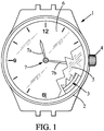
- the support plate 14a is secured to the case 2 of the timepiece 1.
- the energy distribution member 10 may be an escapement wheel mounted to rotate, for example on the support plate 14a, so as to be able to rotate about an axis of rotation Z1 perpendicular to the XY plane of the plate 14. L
- the energy distribution member 10 is requested by the energy storage device 8 in a single direction of rotation 16.
- the energy distribution member 10 has external teeth 17.
- the regulating member of the regulator 12 is connected to the support 15, 115, 215, 315, by an elastic suspension connecting said regulating member to the support. More specifically, said regulating member 18 has substantially an axial symmetry of order n with respect to a central axis Z0 orthogonal to the mean plane XY and fixed relative to the support 15, 115, 215, 315.
- substantially an axial symmetry of order n it is meant that the regulating member 18 is essentially shaped according to this symmetry, but that some parts of relatively negligible mass may not have this symmetry (for example parts used for coupling the anchor with the regulating member).
- Said regulating member 18 comprises a number n of rigid portions interconnected in pairs by n elastic coupling links, not being an integer at least equal to 2.
- the elastic suspension comprises n elastic suspension links respectively connecting each rigid portion of the regulating member to the support 15, 115, 215, 315.
- the elastic suspension can be provided so that the regulating member 18; 118; 218; 318 is movable substantially in rotation about the central axis Z0.
- each rigid portion of the regulating member is connected to two adjacent rigid portions of the regulating member respectively by two elastic coupling links .
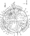
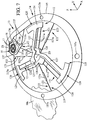
- the regulating member 18 of the regulator 12 may have a generally annular shape centered on the central axis Z0 and comprises 3 rigid portions 20 interconnected two by two by 3 elastic coupling links 21 .
- the elastic suspension 19 which connects the regulating member 18 of the regulator 12 to the support 15, comprises 3 elastic suspension links 22 respectively connecting each rigid portion 20 to the support 15 so that each rigid portion 20 is movable according to at least one rotational movement around the central axis Z0, the regulating member having an overall rotational movement approximately around the central axis Z0.
- Each elastic suspension link 22 advantageously comprises at least one elastic branch 23, for example an elastic branch 23.
- Each elastic branch 23 may optionally include a rigid section 23a, for example towards the center of said elastic branch 23.
- the rigid portions 20 of the regulating member are movable both in rotation and in radial translation relative to the central axis Z0.
- the support 15 may optionally have a substantially star shape, with three branches 15b connected by a central part 15c.
- the rigid portions 20 of the regulating member 18 may each include a portion 24 in the form of an arc of a circle centered on the central axis Z0.
- the parts 24 in the form of a circular arc are adjacent to each other and together form a discontinuous ring centered on the central axis Z0.
- Each elastic branch 23 can extend substantially radially relative to the central axis Z0 and connect the part 24 in the form of a circular arc of one of the rigid portions 20, to the aforementioned central part 15c of the support 15.
- the circular arc shaped portions 24 each extend angularly between a first end 25 and a second end 26 which overlap each other in an angular direction.
- each first end 25 may form a first finger 25a extending towards the adjacent rigid portion 20 and each second end 26 may form a second finger 26a extending towards the adjacent rigid portion 20, each first finger 25a outwardly covering the second finger 26a of the adjacent rigid portion 20.
- each portion 24 in the form of an arc of a circle can be extended substantially radially inwards by a rigid arm 27 terminated by a spout 28 extending angularly beyond the second end, in the direction of the adjacent rigid portion 20.
- Each elastic coupling link 21 may comprise at least one elastic coupling branch 21a (here 2 elastic coupling branches 21a parallel) extending substantially radially with respect to the central axis Z0 and connecting the spout 28 of each rigid portion 20 to the first end 25 of the part 24 in an arc of a circle of the adjacent rigid portion 20.
- each rigid portion 20 of the regulating member may be limited by means for limiting movement with respect to the support 15, to limit the displacements, in particular angular, of the rigid portions 20 and to protect the mechanism 13 in particular in the event of an impact or more generally when it undergoes strong accelerations.
- These movement limitation means may include a slot 29 formed in each part 24 in an arc of a circle and extending angularly around the central axis Z0, and a pin 30 which is integral with the support 15 (in fact, fixed to the support plate 14a) and which is disposed in the slot 29.
- the slots 29 are shaped according to the kinematics of the rigid portions 20 during the rotational movement of the regulating member 18.
- the slots 29 are therefore not of circular shape centered on the central axis Z0, but here rather in the form of sections of spirals.
- the anchor 11 and the energy distribution member 10 can be placed inside the regulating member 18.
- the anchor 11 is a rigid part which may include a rigid body 31 adjacent to the part 24 in the arc of a circle of one of the rigid portions 20 of the regulating member.
- the anchor 11 may further include a rigid drive arm 32 which is integral with the rigid body 31 and which extends towards one of the branches 15b of the support from said rigid body 31.
- the anchor 11 is elastically connected to the support 15, so as to be able to oscillate, for example according to a movement substantially in rotation about an axis Z2 perpendicular to the XY plane.
- the oscillations of the anchor 11 are controlled by the regulating member 18.
- the rigid arm 27 of one of the rigid portions 20 of the regulating member can be extended inwards by an additional rigid arm 33, the free end of which is connected to the free end of the rigid arm of drive 32 by an elastic drive branch 34.
- the anchor 11 can be connected to the support 15 by an elastic suspension, comprising for example two elastic anchor suspension branches 35 converging substantially towards the axis Z2.
- the elastic branches 35 can connect the rigid body 31 to the free end 15e of one of the branches 15b of the support.
- the anchor 11 comprises two stop members 36, 37 in the form of lugs projecting substantially towards the axis Z1, which are adapted to cooperate with the energy distribution member 10.
- the anchor 11 is thus controlled by said member adjusting to regularly and alternately block and release the energy distribution member 10 with the aid of the stop members 36, 37, so that said energy distribution member 10 moves step by step in the direction 16 under the stress of the energy storage device 8 according to a repetitive movement cycle, and said anchor 11 is further adapted to transfer mechanical energy to the regulating member 18 during this repetitive movement cycle, so known per se.
- the total mass of the oscillating parts of the mechanism can be approximately 0.33 g and their inertia approximately 20.19 10 -9 kg.m 2 , the frequency of oscillation of the regulating member is about 18 Hz and the rotational stiffness of the mechanism is about 2.58 10 -4 Nm / rad.
- Such a mechanism exhibits very good isochronism, which leads to very good temporal precision.
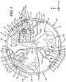
- the regulating member 118 of the regulator 12 comprises 3 rigid portions 120 interconnected in pairs by 3 elastic coupling links 121.
- the elastic suspension 119 which connects the regulating member 118 of the regulator 12 to the support 115, comprises 3 elastic suspension links 122 respectively connecting each rigid portion 120 to the support 115 so that each rigid portion 20 is movable according to at least one rotational movement. around the central axis Z0.
- Each elastic suspension link 122 advantageously comprises at least one elastic branch 123, for example an elastic branch 123.
- Each elastic branch 123 may optionally include a rigid section 123a, for example towards the center of said elastic branch 123.
- the portions rigid 120 of the regulating member are movable both in rotation and in radial translation relative to the central axis Z0.
- the support 115 may optionally have an annular shape surrounding the regulator 118, the energy distribution member 10 and the anchor 11.
- the rigid portions 120 of the regulating member 118 may each include a portion 124 in the form of an arc of a circle centered on the central axis Z0.
- the parts 124 in the form of a circular arc are here relatively spaced apart from each other in the circumferential direction.
- Each rigid portion 120 may further include a rigid arm 127 which extends substantially radially inwardly from the portion 124 in the form of an arc of a circle, to a central end 128 in the form of a heel.
- Each elastic branch 123 can extend substantially radially with respect to the central axis Z0, between the central end 128 of one of the rigid parts 120 and the support 115, passing between two adjacent parts 124.
- Each elastic coupling link 121 can include at least one elastic coupling branch 121a (here 2 elastic coupling branches 121a parallel) extending substantially radially with respect to the central axis Z0 and connecting the central end 128 of each rigid portion 120 to the arcuate portion 124 of an adjacent rigid portion 120.
- the anchor 11 is a rigid part which may for example comprise two integral branches 111a, 111b forming an angle between them, for example of the order of 90 degrees, the branch 111a being here extended beyond the branch 111b by a heel. 111c.
- the anchor 11 is elastically connected to the support 115, so as to be able to oscillate, for example according to a movement substantially in rotation about a perpendicular axis Z2. in the XY plane.
- the oscillations of the anchor 11 are controlled by the regulating member 118.
- the rigid arm 127 of one of the rigid portions 120 of the regulating member can be connected, for example, to the branch 111a of the anchor by an elastic drive branch 134, optionally provided with a rigid central section. 134a.
- the anchor 11 can be connected to the support 115 by an elastic suspension, comprising for example two elastic anchor suspension branches 135 converging substantially towards the axis Z2.
- the elastic branches 135 can connect the heel 111c of the anchor 11 to the support 115.
- the anchor 11 comprises two stop members 136, 137 in the form of lugs projecting substantially towards the axis Z1, which are adapted to cooperate with the energy distribution member 10.
- the anchor 11 is thus controlled by said regulating member 118 to regularly and alternately block and release the energy distribution member 10 by means of the stop members 136, 137, so that said distribution member energy 10 moves step by step in the direction 16 under the stress of the energy storage device 8 in a repetitive motion cycle, and said anchor 11 is further adapted to transfer mechanical energy to the regulating member 118 during this repetitive movement cycle, in a manner known per se.
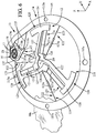
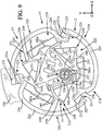
- the regulating member 218 of the regulator 12 may have a generally annular shape centered on the central axis Z0 and comprises 3 rigid portions 220 interconnected two by two by 3 elastic coupling links 221.
- the rigid portions 220 of the regulating member 218 may each include a portion 224 in the form of an arc of a circle centered on the central axis Z0.
- the parts 224 in the form of a circular arc are adjacent to each other and together form a discontinuous ring centered on the central axis Z0.
- the circular arc shaped portions 224 each extend angularly between a first end 225 and a second end 226 which overlap each other in an angular direction.
- each second end 226 may extend at an angle angularly towards the adjacent rigid portion 220 and radially inward, to a spout 228 covered outwardly by the first end 225 of the adjacent rigid portion 220.
- Each elastic coupling link 221 may include at least one elastic coupling branch 221a (here 2 elastic coupling branches 221a parallel) extending substantially radially with respect to the central axis Z0 and connecting the spout 228 of each rigid portion 220 to the first end 225 of the circular arc portion 224 of the adjacent rigid portion 220.
- the support 215 is arranged in the center of the regulating member 218.
- the elastic suspension 219 which connects the regulating member 218 of the regulator 12 to the support 215, comprises 3 elastic suspension links 222 respectively connecting each rigid portion 220 to the support 215 so that each rigid portion 220 is movable according to at least one rotational movement. around the central axis Z0.
- Each elastic suspension link 222 can for example connect the support 215 (for example an angle 215b of the support 215 when this support has a substantially triangular shape as in the example shown).
- Each elastic suspension link 222 can optionally comprising an intermediate rigid body 238 which comprises for example an arcuate portion 239 of concavity oriented towards the corresponding angle 215b of the support 215 and a rigid link arm 240 oriented substantially away from said angle 215b.
- the arcuate part 239 can be connected to said angle 215b, for example by two elastic branches 241 converging towards the angle 215b.
- the rigid link arm 240 can be connected to the second end 226 of the part 224 in the corresponding arc of a circle, for example by two parallel elastic branches 242, possibly comprising rigid central sections 242a.
- the anchor 11 and the energy distribution member 10 may be placed inside the regulating member 218, for example at least partially in a recess 215c made in the support 215.
- the anchor 11 may be formed by a rigid arm 231 which extends parallel to one of the flexible branches 241 of one of the elastic links 222, from one end of the corresponding arcuate portion 239.
- the rigid arm 231 comprises two stop members 236, 237 in the form of lugs projecting substantially towards the axis Z1, which are adapted to cooperate with the energy distribution member 10.
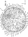
- the regulating member 318 of the regulator 12 may have a generally annular shape centered on the central axis Z0 and comprises 3 rigid portions 320 interconnected two by two by 3 elastic coupling links 321.
- the elastic suspension 319 which connects the regulating member 318 of the regulator 12 to the support 315, comprises 3 elastic suspension links 322 respectively connecting each rigid portion 320 to the support 315 so that each rigid portion 320 is movable according to at least one rotational movement about the central axis Z0.
- Each elastic suspension link 322 advantageously comprises at least one elastic branch 323, for example an elastic branch 323.
- Each elastic branch 323 may optionally include a rigid section 323a, for example towards the center of said elastic branch 323.
- the rigid portions 320 of the regulating member are movable both in rotation and in radial translation relative to the central axis Z0.
- the support 315 may optionally have a substantially star shape, with three branches 315b connected by a central part 315c.
- the rigid portions 320 of the regulating member 318 may each include a portion 324 in the form of an arc of a circle centered on the central axis Z0.
- the parts 324 in the form of an arc of a circle are close to each other and together form a discontinuous ring centered on the central axis Z0.
- Each elastic branch 323 can extend substantially radially relative to the central axis Z0 and connect the part 324 in the form of a circular arc of one of the rigid portions 320, to the aforementioned central part 315c of the support 315.
- the parts 324 in the form of a circular arc each extend angularly between a first end 325 and a second end 326.
- the second end 326 of each part 324 in the form of an arc of a circle can be extended substantially radially inwardly. by a rigid arm 327 terminated by a spout 328 extending angularly beyond the second end, in direction of the adjacent rigid portion 320.
- Each elastic coupling link 321 may comprise at least one elastic coupling branch 321a (here 2 elastic coupling branches 321a parallel) extending substantially radially with respect to the central axis Z0 and connecting the spout 328 of each rigid portion 320 to the first end 325 of the circular arc portion 324 of the adjacent rigid portion 320.
- the deflections of at least certain rigid portions 320 of the regulating member can be limited by movement limiting means relative to the support 15, to limit the displacements, in particular angular, of the rigid portions 320 and to protect the mechanism, in particular in the event of an impact. or more generally when it undergoes strong accelerations.
- These movement limitation means may comprise a rigid movement limitation arm 329 belonging to at least one rigid portion 320 of the regulating member 318, and two complementary movement limitation members 330a belonging to the support 315 and radially framing said control arm.
- movement limitation 329, said movement limitation arm extending angularly with respect to the central axis Z0.
- the rigid movement limiting arm 329 can penetrate into a recess 330 made in the support 315. Said recess 330 opens out of said support 315 in the XY plane through a narrowed opening delimited by two flanges belonging to said support and forming said limitation members.
- complementary movement 330a complementary movement 330a.
- each movement limitation arm 329 may include a free end provided with a head 329b widened in the radial direction, said head 329b being disposed in the recess 330 and being wider than the distance between the two limitation members. additional movement 330a belonging to the support.
- Each recess 330 may be shaped substantially as a circular arc centered on the central axis Z0, and each movement limiting arm may be shaped substantially as a circular arc centered on the central axis, or more advantageously as a portion of a corresponding spiral. with the kinematics of the rigid portions 320 of the regulating member 318.
- one of the branches 315b of the support 315 comprises a recess 315d which accommodates the energy distribution member 10 and the anchor 11, and each of the other two branches 315c comprises two recesses 330 opening out to the 'opposite one another and respectively receiving two movement limiting arms 329 extending towards each other, belonging to one of the rigid portions 320.
- One of the rigid portions 320 may be devoid of arms limitation of movement 329 but be coupled to the anchor 11 as will be explained below.
- one of the two movement limitation arms 329 of each rigid portion 320 may be integral with a support arm 329a extending radially inward from the portion 324 in the arc of a circle of this portion. rigid 320, in the vicinity of the first end 325 of said part 324 in the form of an arc of a circle.
- the other movement limitation arm 329 of the same rigid portion 320 may be integral with the aforementioned rigid arm 327.
- the anchor 11 is a rigid part which may include a rigid body 331 adjacent to the part 324 in the arc of a circle of one of the rigid portions 320 of the regulating member (that which is devoid of movement limiting arm 329 in the example considered).
- the anchor 11 may further include a rigid drive arm 332 which is integral with the rigid body 331.
- the anchor 11 is elastically connected to the support 315, so as to be able to oscillate, for example according to a movement substantially in rotation about an axis Z2 perpendicular to the XY plane.
- the oscillations of the anchor 11 are controlled by the regulating member 318.
- the rigid arm 327 of the rigid portion 320 adjacent to the anchor 11 can be extended inwards by an additional rigid arm 333, the free end of which is connected to the free end of the rigid drive arm. 332 by a resilient drive branch 334 (possibly provided with a rigid central section 334a).
- the anchor 11 can be connected to the support 315 by an elastic suspension, comprising for example two elastic anchor suspension branches 335 converging substantially towards the axis Z2.
- the anchor 11 comprises two stop members 336, 337 in the form of lugs projecting substantially towards the axis Z1, which are adapted to cooperate with the energy distribution member 10.
- the anchor 11 is thus controlled by said regulating member 318 to regularly and alternately block and release the energy distribution member 10 by means of the stop members 336, 337, so that said distribution member energy 10 moves step by step in the direction 16 under the stress of the energy storage device 8 in a repetitive cycle of movement, and said anchor 11 is further adapted to transfer mechanical energy to the regulating member 18 during this repetitive movement cycle, in a manner known per se.
- the anchor 11 may further include a monostable elastic member 341, which may be in the in the form of an elastic tongue whose free end bears on the teeth 17 of the energy distribution member 10.
- the monostable elastic member 341 can be connected to the rigid body 331 of the anchor 11, for example by an elastic suspension comprising two substantially parallel elastic branches 339 extending to a rigid support 340 which carries the monostable elastic member 341.
- the monostable elastic member 341 serves for the energy distribution member 10 to transfer a mechanical energy precisely determined at the regulating member 318, at each operating cycle of the watch movement 3, as explained in the document WO2016091951 .
Claims (24)
- Vorrichtung für Uhren, aufweisend einen sich in einer mittleren Ebene (XY) erstreckenden flachen Mechanismus (13), wobei der Mechanismus (13) aufweist:- einen Träger (15; 115; 215; 315),- ein regelndes Trägheitselement (18; 118; 218; 318), das über eine elastische Aufhängung (19; 119; 219; 319) mit dem Träger (15; 115; 215; 315) verbunden ist, wobei das regelnde Element (18; 118; 218; 318) im Wesentlichen eine axiale Symmetrie der Ordnung n bezüglich einer zentralen Achse aufweist, die orthogonal zur mittleren Ebene und stationär bezüglich des Trägers ist, wobei n eine ganze Zahl mindestens gleich 2 ist,in welcher das regelnde Element (18; 118; 218; 318) eine Anzahl n von starren Abschnitten (20; 120; 220; 320) aufweist, die über n elastische Kopplungsverbindungen (21; 121; 221; 321) zu zweit miteinander verbunden sind,
und die elastische Aufhängung (19; 119; 219; 319) n elastische Aufhängungsverbindungen (22; 122; 222; 322) aufweist, die sich von den elastischen Kopplungsverbindungen unterscheiden und jeweils jeden starren Abschnitt (20; 120; 220; 320) mit dem Träger verbinden. - Vorrichtung nach Anspruch 1, in welcher das regelnde Element (18; 118; 218; 318) im Wesentlichen rotierbar um die zentrale Achse (Z0) ist.
- Vorrichtung nach Anspruch 2, in welcher die starren Abschnitte (20; 120; 220; 320) des regelnden Elements (18; 118; 218; 318) sowohl rotierbar als auch verschiebbar bezüglich der zentralen Achse (20) sind.
- Vorrichtung nach einem der vorstehenden Ansprüche, in welcher die elastischen Aufhängungsverbindungen (22; 122; 222; 322) jeweils mindestens einen elastischen Schenkel (23; 123; 223; 323) aufweisen.
- Vorrichtung nach einem der vorstehenden Ansprüche, in welcher die Anzahl n mindestens gleich drei ist und jeder starre Abschnitt (20; 120; 220; 320) jeweils über zwei elastische Kopplungsverbindungen (21; 121; 221; 321) mit zwei benachbarten starren Abschnitten (20; 120; 220; 320) verbunden ist.
- Vorrichtung nach einem der vorstehenden Ansprüche, in welcher die Anzahl n gleich 3 ist.
- Vorrichtung nach einem der vorstehenden Ansprüche, in welcher die starren Abschnitte (20; 120; 220; 320) jeweils einen bezüglich der zentralen Achse (Z0) zentrierten kreisbogenförmigen Teil (24; 124; 224; 324) aufweisen.
- Vorrichtung nach Anspruch 7, in welcher die kreisbogenförmigen Teile (24; 224; 324) zueinander benachbart sind und zusammen einen diskontinuierlichen Ring bilden.
- Vorrichtung nach Anspruch 8, in welcher die kreisbogenförmigen Teile (24; 224) sich jeweils in Winkelrichtung zwischen einem ersten Ende (25; 225) und einem zweiten Ende (26; 126) erstrecken, die sich in Winkelrichtung gegenseitig überlappen.
- Vorrichtung nach Anspruch 8 oder Anspruch 9, in welcher die kreisbogenförmigen Teile (24; 324) sich in Winkelrichtung jeweils zwischen einem ersten Ende (25; 325) und einem zweiten Ende (26; 326) erstrecken, wobei das zweite Ende durch einen starren Arm (27; 327) radial verlängert ist, der mit einem Schnabel (28; 328) endet, der sich in Winkelrichtung über das zweite Ende (26; 326) hinaus erstreckt, und jede elastische Kopplungsverbindung (21; 321) mindestens einen elastischen Kopplungsschenkel (21a; 321a) aufweist, der sich im Wesentlichen radial bezüglich der zentralen Achse (Z0) erstreckt und den Schnabel (28; 328) jedes starren Abschnitts mit dem ersten Ende (25; 325) des kreisbogenförmigen Teils eines benachbarten Abschnitts verbindet.
- Vorrichtung nach einem der vorstehenden Ansprüche, in welcher der Träger (15; 215; 315) mindestens einen zentralen Teil aufweist, der von den starren Abschnitten (20; 220; 320) des regelnden Elements umgeben ist, und jede elastische Aufhängungsverbindung (22; 222; 322) mindestens einen elastischen Aufhängungsschenkel (23; 223; 323) aufweist, der sich von dem entsprechenden starren Abschnitt im Wesentlichen radial einwärts zu dem zentralen Teil des Trägers erstreckt.
- Vorrichtung nach einem der vorstehenden Ansprüche, in welcher der Mechanismus (13) ferner einen Anker (11) aufweist, der eingerichtet ist, mit einem Energieverteilungselement (10) zusammenzuarbeiten, das mit Zähnen (17) versehen ist und vorgesehen ist, von einer Energiespeichervorrichtung (8) vorgespannt zu werden, wobei der Anker (11) von dem regelnden Element (18; 118; 218; 318) gesteuert wird, um das Energieverteilungselement (10) regelmäßig und abwechselnd zu sperren und freizugeben, derart, dass unter der Vorspannung der Energiespeichervorrichtung (8) das Energieverteilungselement (10) Schritt für Schritt gemäß einem sich wiederholenden Bewegungszyklus vorrückt, und der Anker (11) eingerichtet ist, im Verlaufe dieses sich wiederholenden Bewegungszyklus mechanische Energie auf das regelnde Element (18; 118; 218; 318) zu übertragen.
- Vorrichtung nach Anspruch 12, in welcher der Anker (11) über zwei elastische Ankeraufhängungsschenkel (35; 135; 241; 335) mit dem Träger (15; 15; 215; 315) und über mindestens einen elastischen Antriebsschenkel (34; 134; 234; 334) mit einem der starren Abschnitte (20; 120; 220; 320) des regelnden Elements verbunden ist.
- Vorrichtung nach Anspruch 13, in welcher die elastischen Ankeraufhängungsschenkel (35; 135; 241; 335) angeordnet sind, damit der Anker (11) im Wesentlichen um eine zusätzliche Rotationsachse (Z2) rotierbar ist, die parallel zur zentralen Achse (Z0) ist.
- Vorrichtung nach einem der Ansprüche 13 bis 14, in welcher der Anker (11) einen starren Hauptkörper (31; 331) aufweist, der zwei Sperrglieder (36, 37; 336, 337) aufweist, die eingerichtet sind, mit den Zähnen (17) des Energieverteilungselements (10) zusammenzuarbeiten, wobei der Hauptkörper des Ankers innenliegend bezüglich des kreisbogenförmigen Teils (24; 324) eines der starren Körpers angeordnet ist, und der Anker (11) ferner einen starren Antriebsarm (32; 332) aufweist, der integral mit dem Hauptkörper ist und über den elastischen Antriebsschenkel (34; 334) mit dem starren Arm des starren Abschnitts verbunden ist.
- Vorrichtung nach einem der vorstehenden Ansprüche, aufweisend Bewegungsbegrenzungseinrichtungen (29, 30; 329, 330a), die eingerichtet sind, die Ausschläge mindestens eines starren Abschnitts (20; 320) des regelnden Elements bezüglich des Trägers zu begrenzen.
- Vorrichtung nach Anspruch 16, in welcher die Bewegungsbegrenzungseinrichtungen (29, 30; 329, 330a) einen Winkelausschlag des mindestens einen starren Abschnitts des regelnden Elements um die zentrale Achse bezüglich des Trägers begrenzen.
- Vorrichtung nach Anspruch 16 oder Anspruch 17, in welcher die Bewegungsbegrenzungseinrichtungen aufweisen: einen Schlitz (29), der in dem mindestens einen starren Abschnitt (20; 320) des regelnden Elements ausgespart ist und sich in Winkelrichtung um die zentrale Achse (Z0) erstreckt, und einen Stift (30), der mit dem Träger (15) integral ist und der in dem Schlitz (29) angeordnet ist.
- Vorrichtung nach Anspruch 16 oder Anspruch 17, in welcher die Bewegungsbegrenzungseinrichtungen aufweisen: einen starren Bewegungsbegrenzungsarm (329), der dem mindestens einen starren Abschnitt (320) des regelnden Elements zugehörig ist, und zwei komplementäre Bewegungsbegrenzungselemente (330a), die dem Träger (315) zugehörig sind und den Bewegungsbegrenzungsarm (329) radial umrahmen, wobei der Bewegungsbegrenzungsarm (329) sich in Winkelrichtung bezüglich der zentralen Achse (Z0) erstreckt.
- Vorrichtung nach Anspruch 19, in welcher der Bewegungsbegrenzungsarm (329) ein freies Ende aufweist, das mit einem in radialer Richtung verbreiterten Kopf (329b) versehen ist, wobei der Kopf (329b) breiter ist als der Abstand zwischen den zwei komplementären Bewegungsbegrenzungselementen (330a), die dem Träger zugehörig sind.
- Vorrichtung nach Anspruch 20, in welcher der verbreiterte Kopf (329b) in einer bezüglich der zentralen Achse (Z0) zentrierten kreisbogenförmigen Aussparung (330), die in dem Träger gebildet ist, in Winkelrichtung beweglich ist, wobei die Aussparung über eine eingeengte Öffnung, die von zwei Randkanten (330a) begrenzt ist, die dem Träger zugehörig sind und die komplementären Bewegungsbegrenzungselemente bilden, aus dem Träger ausmündet.
- Vorrichtung nach einem der Ansprüche 1 bis 10, in welcher
der Träger (115) mindestens teilweise um das regelnde Element (118) herum angeordnet ist,
jeder starre Abschnitt (120) einen bezüglich der zentralen Achse (Z0) zentrierten kreisbogenförmigen Teil (124) und einen starren Arm (127), der sich von dem kreisbogenförmigen Teil (124) zu einem der zentralen Achse benachbarten inneren Ende (128) erstreckt, aufweist,
jede elastische Aufhängungsverbindung (122) einen elastischen Aufhängungsschenkel (123) aufweist, der den Träger (115) mit dem inneren Ende (128) des starren Arms verbindet und sich im Wesentlichen radial bezüglich der zentralen Achse (Z0) erstreckt, und
jede elastische Kopplungsverbindung (121) mindestens einen elastischen Kopplungsschenkel (121a) aufweist, der den kreisbogenförmigen Teil (124) eines starren Abschnitts mit dem inneren Ende (128) des starren Arms (127) eines benachbarten starren Abschnitts verbindet, wobei der elastische Kopplungsschenkel (121a) sich im Wesentlichen radial bezüglich der zentralen Achse (Z0) erstreckt. - Uhrgangwerk (3) aufweisend eine Vorrichtung (13) nach einem der vorstehenden Ansprüche und ein Energieverteilungselement (10), das mit Zähnen (17) versehen ist und vorgesehen ist, von einer Energiespeichervorrichtung (8) vorgespannt zu werden, wobei die Vorrichtung (13) einen Anker (11) aufweist, der eingerichtet ist, mit dem Energieverteilungselement (10) zusammenzuarbeiten, wobei der Anker (11) von dem regelnden Element (18; 118; 218; 318) gesteuert wird, um das Energieverteilungselement (10) regelmäßig und abwechselnd zu sperren und freizugeben, derart, dass unter der Vorspannung der Energiespeichervorrichtung (8) das Energieverteilungselement (10) Schritt für Schritt gemäß einem sich wiederholenden Bewegungszyklus vorrückt, und der Anker (11) eingerichtet ist, im Verlaufe dieses sich wiederholenden Bewegungszyklus mechanische Energie auf das regelnde Element (18; 118; 218; 318) zu übertragen.
- Uhr (1) aufweisend ein Uhrgangwerk (3) nach Anspruch 23.
Applications Claiming Priority (2)
| Application Number | Priority Date | Filing Date | Title |
|---|---|---|---|
| FR1661782A FR3059792B1 (fr) | 2016-12-01 | 2016-12-01 | Dispositif pour piece d'horlogerie, mouvement horloger et piece d'horlogerie comprenant un tel dispositif |
| PCT/EP2017/081087 WO2018100122A1 (fr) | 2016-12-01 | 2017-11-30 | Dispositif pour pièce d'horlogerie, mouvement horloger et pièce d'horlogerie comprenant un tel dispositif |
Publications (2)
| Publication Number | Publication Date |
|---|---|
| EP3548973A1 EP3548973A1 (de) | 2019-10-09 |
| EP3548973B1 true EP3548973B1 (de) | 2021-01-27 |
Family
ID=57963354
Family Applications (1)
| Application Number | Title | Priority Date | Filing Date |
|---|---|---|---|
| EP17805224.7A Active EP3548973B1 (de) | 2016-12-01 | 2017-11-30 | Vorrichtung für uhren, uhrmechanismus und uhr mit einer solchen vorrichtung. |
Country Status (7)
| Country | Link |
|---|---|
| US (1) | US11934149B2 (de) |
| EP (1) | EP3548973B1 (de) |
| JP (1) | JP7058655B2 (de) |
| CN (1) | CN110692022B (de) |
| FR (1) | FR3059792B1 (de) |
| TW (1) | TW201830175A (de) |
| WO (1) | WO2018100122A1 (de) |
Families Citing this family (10)
| Publication number | Priority date | Publication date | Assignee | Title |
|---|---|---|---|---|
| EP3667432B1 (de) | 2018-12-13 | 2022-05-11 | ETA SA Manufacture Horlogère Suisse | Uhrresonator, der mindestens eine flexible führung umfasst |
| CH714992A9 (fr) | 2019-01-24 | 2020-01-15 | Csem Centre Suisse Delectronique Et De Microtechnique Sa | Régulateur horloger mécanique. |
| FR3093193B1 (fr) * | 2019-02-22 | 2021-03-19 | Lvmh Swiss Mft Sa | Oscillateur pour mécanisme de pièce d’horlogerie |
| EP3708384A1 (de) | 2019-03-14 | 2020-09-16 | Omega SA | Verkleidungselement oder zifferblatt einer uhr oder eines schmuckstücks aus leitendem material |
| EP3722888B1 (de) | 2019-04-09 | 2023-05-17 | Ecole Polytechnique Fédérale de Lausanne (EPFL) | Mechanischer oszillator mit abstimmbarem isochronismusmangel |
| EP3792700B1 (de) * | 2019-09-16 | 2023-10-04 | Patek Philippe SA Genève | Oszillator einer uhr mit flexiblem zapfen |
| NL2024076B1 (en) * | 2019-10-22 | 2021-07-13 | Flexous Mech Ip B V | A mechanical watch |
| EP4047424A1 (de) | 2021-02-18 | 2022-08-24 | Patek Philippe SA Genève | Komponente mit flexiblem zapfen, insbesondere für uhrwerk |
| NL2029135B1 (en) * | 2021-09-06 | 2023-03-21 | Flexous Mech Ip B V | A mechanical watch |
| EP4246245A1 (de) | 2022-03-18 | 2023-09-20 | Flexous Mechanisms IP B.V. | Uhrwerk für eine uhr |
Family Cites Families (20)
| Publication number | Priority date | Publication date | Assignee | Title |
|---|---|---|---|---|
| CH428578A (de) * | 1964-08-10 | 1966-08-31 | Centre Electron Horloger | Mechanischer Resonator für Normalfrequenzoszillatoren in Zeitmessgeräten |
| DE1260211B (de) | 1965-07-15 | 1968-02-01 | Kienzle Apparate Gmbh | Steuereinrichtung fuer den Ruettelantrieb von Registriermitteln in einem Fahrtschreiber oder aehnlichem Registriergeraet |
| DE602008006057D1 (de) * | 2008-07-04 | 2011-05-19 | Swatch Group Res & Dev Ltd | Gekoppelte Resonatoren für Uhr |
| HK1146455A2 (en) * | 2010-03-12 | 2011-06-03 | Microtechne Res & Dev Ct Ltd | An oscillator system |
| CH703274B1 (fr) * | 2010-06-11 | 2015-03-31 | Montres Breguet Sa | Balancier haute fréquence pour pièce d'horlogerie, balancier-spiral et pièce d'horlogerie incorporant un tel balancier. |
| CN103097965B (zh) * | 2010-07-19 | 2015-05-13 | 尼瓦洛克斯-法尔股份有限公司 | 具有弹性枢轴的振荡机构和用于传递能量的可动元件 |
| EP2410387B1 (de) | 2010-07-19 | 2016-07-06 | Nivarox-FAR S.A. | Unruh mit Trägheitsregulierung ohne Einsatzteil |
| EP2533109B1 (de) * | 2011-06-09 | 2019-03-13 | Cartier International AG | Mechanismus zur vermeidung der schwerkraftbedingten gangvariationen auf einer reguliervorrichtung mit spiralunruh, und mit dieser perfektionierung ausgestattete uhr |
| EP2615503B1 (de) * | 2012-01-13 | 2014-09-24 | Agenhor SA | Steuermechanismus eines Federhaus für Uhrwerk |
| RU2607339C9 (ru) * | 2012-03-29 | 2017-02-22 | Ниварокс-Фар С.А. | Механизм анкерный гибкий с подвижной рамой |
| CH707471B1 (fr) * | 2013-08-05 | 2014-07-31 | Rd Engineering Rudolf Dinger | Système régulateur pour montre mécanique. |
| EP2874023A1 (de) * | 2013-11-13 | 2015-05-20 | ETA SA Manufacture Horlogère Suisse | Uhr, die eine Entkoppelung zwischen den Energieübertragungsmitteln und den Zeitzählmitteln umfasst |
| EP2911012B1 (de) * | 2014-02-20 | 2020-07-22 | CSEM Centre Suisse d'Electronique et de Microtechnique SA - Recherche et Développement | Oszillator einer Uhr |
| CH710115A2 (fr) * | 2014-09-09 | 2016-03-15 | Swatch Group Res & Dev Ltd | Mobile coupleur pour la synchronisation de résonateurs d'horlogerie de même fréquence. |
| EP3021174A1 (de) | 2014-11-17 | 2016-05-18 | LVMH Swiss Manufactures SA | Monolithischer Uhrregler, Uhrwerk und Uhr mit einem solchem Uhrregler |
| KR20170125803A (ko) * | 2014-12-09 | 2017-11-15 | 엘브이엠에이치 스위스 매뉴팩츄어스 에스에이 | 시계용 장치 및 상기 장치를 구비한 시계 |
| EP3032351A1 (de) * | 2014-12-09 | 2016-06-15 | LVMH Swiss Manufactures SA | Uhrmechanismus, Uhrwerk und Uhr mit solch einem Mechanismus |
| CH710537A2 (fr) | 2014-12-18 | 2016-06-30 | Swatch Group Res & Dev Ltd | Oscillateur d'horlogerie à diapason. |
| CH710692B1 (fr) * | 2015-02-03 | 2021-09-15 | Eta Sa Mft Horlogere Suisse | Mécanisme oscillateur d'horlogerie. |
| CH710759A2 (fr) | 2015-02-20 | 2016-08-31 | Nivarox Far Sa | Oscillateur pour une pièce d'horlogerie. |
-
2016
- 2016-12-01 FR FR1661782A patent/FR3059792B1/fr active Active
-
2017
- 2017-11-30 WO PCT/EP2017/081087 patent/WO2018100122A1/fr unknown
- 2017-11-30 EP EP17805224.7A patent/EP3548973B1/de active Active
- 2017-11-30 CN CN201780083855.7A patent/CN110692022B/zh active Active
- 2017-11-30 US US16/465,912 patent/US11934149B2/en active Active
- 2017-11-30 JP JP2019529590A patent/JP7058655B2/ja active Active
- 2017-12-01 TW TW106142126A patent/TW201830175A/zh unknown
Non-Patent Citations (1)
| Title |
|---|
| None * |
Also Published As
| Publication number | Publication date |
|---|---|
| FR3059792A1 (fr) | 2018-06-08 |
| US20200073329A1 (en) | 2020-03-05 |
| EP3548973A1 (de) | 2019-10-09 |
| WO2018100122A1 (fr) | 2018-06-07 |
| FR3059792B1 (fr) | 2019-05-24 |
| JP2019536053A (ja) | 2019-12-12 |
| CN110692022B (zh) | 2021-04-13 |
| CN110692022A (zh) | 2020-01-14 |
| JP7058655B2 (ja) | 2022-04-22 |
| US11934149B2 (en) | 2024-03-19 |
| TW201830175A (zh) | 2018-08-16 |
Similar Documents
| Publication | Publication Date | Title |
|---|---|---|
| EP3548973B1 (de) | Vorrichtung für uhren, uhrmechanismus und uhr mit einer solchen vorrichtung. | |
| EP3182213B1 (de) | Einstellmechanismus der mittleren geschwindigkeit in einem uhrwerk, und entsprechendes uhrwerk | |
| EP3457221A2 (de) | Oszillator einer uhr mit flexiblem zapfen | |
| EP3430479B1 (de) | Vorrichtung für eine uhr, uhrwerk und uhr mit solch einer vorrichtung | |
| EP2690507B1 (de) | Spiralfeder einer Uhr | |
| EP3430478B1 (de) | Mechanismus für eine uhr und uhr mit solch einem mechanismus | |
| EP3792700B1 (de) | Oszillator einer uhr mit flexiblem zapfen | |
| EP2908183B1 (de) | Spiralfeder einer Uhr | |
| FR3071075B1 (fr) | Dispositif pour piece d'horlogerie, mouvement horloger et piece d'horlogerie comprenant un tel dispositif | |
| EP3037893B1 (de) | Mikromechanische Komponente oder Uhr mit flexiblem Führungsdraht | |
| CH713790B1 (fr) | Mécanisme pour pièce d'horlogerie, mouvement horloger et pièce d'horlogerie comprenant un tel mécanisme. | |
| EP3839651B1 (de) | Mechanischer oszillator einer uhr mit flexibler führung | |
| WO2017102917A1 (fr) | Oscillateur mécanique pour pièce d'horlogerie, mécanisme de réglage comportant cet oscillateur mécanique, et mouvement d'horlogerie | |
| FR3048792B1 (fr) | Dispositif pour piece d'horlogerie, mouvement horloger et piece d'horlogerie comprenant un tel dispositif | |
| EP3451073B1 (de) | Uhrwerkoszillator mit flexiblen führungen mit grosser winkelförmiger laufbahn | |
| EP3637196A1 (de) | Mechanischer oszillator | |
| EP3812843A1 (de) | Flexible führung und gesamtheit von übereinander angeordneten flexiblen führungen für sich drehenden resonatormechanismus, insbesondere für uhrwerk | |
| EP3435171B1 (de) | Uhrwerkoszillator mit flexiblen führungen mit grosser winkelförmiger laufbahn | |
| CH714767B1 (fr) | Dispositif de collecte d'énergie mécanique notamment pour pièce d'horlogerie, mouvement horloger et pièce d'horlogerie comprenant un tel dispositif. | |
| CH717059B1 (fr) | Masselotte de réglage. | |
| CH713791B1 (fr) | Micro mécanisme à réglage de position, mouvement horloger et pièce d'horlogerie comprenant un tel mécanisme. | |
| CH716728A2 (fr) | Guidage flexible et ensemble de guidages flexibles superposés pour mécanisme résonateur rotatif, notamment d'un mouvement d'horlogerie. | |
| CH714771B1 (fr) | Dispositif de stockage d'énergie mécanique notamment pour pièce d'horlogerie, mouvement horloger et pièce d'horlogerie comprenant un tel dispositif. |
Legal Events
| Date | Code | Title | Description |
|---|---|---|---|
| STAA | Information on the status of an ep patent application or granted ep patent |
Free format text: STATUS: UNKNOWN |
|
| STAA | Information on the status of an ep patent application or granted ep patent |
Free format text: STATUS: THE INTERNATIONAL PUBLICATION HAS BEEN MADE |
|
| PUAI | Public reference made under article 153(3) epc to a published international application that has entered the european phase |
Free format text: ORIGINAL CODE: 0009012 |
|
| STAA | Information on the status of an ep patent application or granted ep patent |
Free format text: STATUS: REQUEST FOR EXAMINATION WAS MADE |
|
| 17P | Request for examination filed |
Effective date: 20190628 |
|
| AK | Designated contracting states |
Kind code of ref document: A1 Designated state(s): AL AT BE BG CH CY CZ DE DK EE ES FI FR GB GR HR HU IE IS IT LI LT LU LV MC MK MT NL NO PL PT RO RS SE SI SK SM TR |
|
| AX | Request for extension of the european patent |
Extension state: BA ME |
|
| DAV | Request for validation of the european patent (deleted) | ||
| DAX | Request for extension of the european patent (deleted) | ||
| GRAP | Despatch of communication of intention to grant a patent |
Free format text: ORIGINAL CODE: EPIDOSNIGR1 |
|
| STAA | Information on the status of an ep patent application or granted ep patent |
Free format text: STATUS: GRANT OF PATENT IS INTENDED |
|
| INTG | Intention to grant announced |
Effective date: 20200708 |
|
| GRAJ | Information related to disapproval of communication of intention to grant by the applicant or resumption of examination proceedings by the epo deleted |
Free format text: ORIGINAL CODE: EPIDOSDIGR1 |
|
| STAA | Information on the status of an ep patent application or granted ep patent |
Free format text: STATUS: REQUEST FOR EXAMINATION WAS MADE |
|
| GRAS | Grant fee paid |
Free format text: ORIGINAL CODE: EPIDOSNIGR3 |
|
| STAA | Information on the status of an ep patent application or granted ep patent |
Free format text: STATUS: GRANT OF PATENT IS INTENDED |
|
| GRAP | Despatch of communication of intention to grant a patent |
Free format text: ORIGINAL CODE: EPIDOSNIGR1 |
|
| INTC | Intention to grant announced (deleted) | ||
| GRAA | (expected) grant |
Free format text: ORIGINAL CODE: 0009210 |
|
| STAA | Information on the status of an ep patent application or granted ep patent |
Free format text: STATUS: THE PATENT HAS BEEN GRANTED |
|
| INTG | Intention to grant announced |
Effective date: 20201208 |
|
| AK | Designated contracting states |
Kind code of ref document: B1 Designated state(s): AL AT BE BG CH CY CZ DE DK EE ES FI FR GB GR HR HU IE IS IT LI LT LU LV MC MK MT NL NO PL PT RO RS SE SI SK SM TR |
|
| REG | Reference to a national code |
Ref country code: GB Ref legal event code: FG4D Free format text: NOT ENGLISH |
|
| REG | Reference to a national code |
Ref country code: CH Ref legal event code: EP |
|
| REG | Reference to a national code |
Ref country code: AT Ref legal event code: REF Ref document number: 1358926 Country of ref document: AT Kind code of ref document: T Effective date: 20210215 |
|
| REG | Reference to a national code |
Ref country code: IE Ref legal event code: FG4D Free format text: LANGUAGE OF EP DOCUMENT: FRENCH |
|
| REG | Reference to a national code |
Ref country code: DE Ref legal event code: R096 Ref document number: 602017032189 Country of ref document: DE |
|
| REG | Reference to a national code |
Ref country code: CH Ref legal event code: NV Representative=s name: VALIPAT S.A. C/O BOVARD SA NEUCHATEL, CH |
|
| REG | Reference to a national code |
Ref country code: NL Ref legal event code: MP Effective date: 20210127 |
|
| REG | Reference to a national code |
Ref country code: LT Ref legal event code: MG9D |
|
| REG | Reference to a national code |
Ref country code: AT Ref legal event code: MK05 Ref document number: 1358926 Country of ref document: AT Kind code of ref document: T Effective date: 20210127 |
|
| PG25 | Lapsed in a contracting state [announced via postgrant information from national office to epo] |
Ref country code: NO Free format text: LAPSE BECAUSE OF FAILURE TO SUBMIT A TRANSLATION OF THE DESCRIPTION OR TO PAY THE FEE WITHIN THE PRESCRIBED TIME-LIMIT Effective date: 20210427 Ref country code: PT Free format text: LAPSE BECAUSE OF FAILURE TO SUBMIT A TRANSLATION OF THE DESCRIPTION OR TO PAY THE FEE WITHIN THE PRESCRIBED TIME-LIMIT Effective date: 20210527 Ref country code: FI Free format text: LAPSE BECAUSE OF FAILURE TO SUBMIT A TRANSLATION OF THE DESCRIPTION OR TO PAY THE FEE WITHIN THE PRESCRIBED TIME-LIMIT Effective date: 20210127 Ref country code: GR Free format text: LAPSE BECAUSE OF FAILURE TO SUBMIT A TRANSLATION OF THE DESCRIPTION OR TO PAY THE FEE WITHIN THE PRESCRIBED TIME-LIMIT Effective date: 20210428 Ref country code: HR Free format text: LAPSE BECAUSE OF FAILURE TO SUBMIT A TRANSLATION OF THE DESCRIPTION OR TO PAY THE FEE WITHIN THE PRESCRIBED TIME-LIMIT Effective date: 20210127 Ref country code: LT Free format text: LAPSE BECAUSE OF FAILURE TO SUBMIT A TRANSLATION OF THE DESCRIPTION OR TO PAY THE FEE WITHIN THE PRESCRIBED TIME-LIMIT Effective date: 20210127 Ref country code: BG Free format text: LAPSE BECAUSE OF FAILURE TO SUBMIT A TRANSLATION OF THE DESCRIPTION OR TO PAY THE FEE WITHIN THE PRESCRIBED TIME-LIMIT Effective date: 20210427 |
|
| PG25 | Lapsed in a contracting state [announced via postgrant information from national office to epo] |
Ref country code: SE Free format text: LAPSE BECAUSE OF FAILURE TO SUBMIT A TRANSLATION OF THE DESCRIPTION OR TO PAY THE FEE WITHIN THE PRESCRIBED TIME-LIMIT Effective date: 20210127 Ref country code: AT Free format text: LAPSE BECAUSE OF FAILURE TO SUBMIT A TRANSLATION OF THE DESCRIPTION OR TO PAY THE FEE WITHIN THE PRESCRIBED TIME-LIMIT Effective date: 20210127 Ref country code: PL Free format text: LAPSE BECAUSE OF FAILURE TO SUBMIT A TRANSLATION OF THE DESCRIPTION OR TO PAY THE FEE WITHIN THE PRESCRIBED TIME-LIMIT Effective date: 20210127 Ref country code: RS Free format text: LAPSE BECAUSE OF FAILURE TO SUBMIT A TRANSLATION OF THE DESCRIPTION OR TO PAY THE FEE WITHIN THE PRESCRIBED TIME-LIMIT Effective date: 20210127 Ref country code: LV Free format text: LAPSE BECAUSE OF FAILURE TO SUBMIT A TRANSLATION OF THE DESCRIPTION OR TO PAY THE FEE WITHIN THE PRESCRIBED TIME-LIMIT Effective date: 20210127 |
|
| PG25 | Lapsed in a contracting state [announced via postgrant information from national office to epo] |
Ref country code: IS Free format text: LAPSE BECAUSE OF FAILURE TO SUBMIT A TRANSLATION OF THE DESCRIPTION OR TO PAY THE FEE WITHIN THE PRESCRIBED TIME-LIMIT Effective date: 20210527 |
|
| REG | Reference to a national code |
Ref country code: DE Ref legal event code: R097 Ref document number: 602017032189 Country of ref document: DE |
|
| PG25 | Lapsed in a contracting state [announced via postgrant information from national office to epo] |
Ref country code: SM Free format text: LAPSE BECAUSE OF FAILURE TO SUBMIT A TRANSLATION OF THE DESCRIPTION OR TO PAY THE FEE WITHIN THE PRESCRIBED TIME-LIMIT Effective date: 20210127 Ref country code: EE Free format text: LAPSE BECAUSE OF FAILURE TO SUBMIT A TRANSLATION OF THE DESCRIPTION OR TO PAY THE FEE WITHIN THE PRESCRIBED TIME-LIMIT Effective date: 20210127 Ref country code: CZ Free format text: LAPSE BECAUSE OF FAILURE TO SUBMIT A TRANSLATION OF THE DESCRIPTION OR TO PAY THE FEE WITHIN THE PRESCRIBED TIME-LIMIT Effective date: 20210127 |
|
| PG25 | Lapsed in a contracting state [announced via postgrant information from national office to epo] |
Ref country code: DK Free format text: LAPSE BECAUSE OF FAILURE TO SUBMIT A TRANSLATION OF THE DESCRIPTION OR TO PAY THE FEE WITHIN THE PRESCRIBED TIME-LIMIT Effective date: 20210127 Ref country code: SK Free format text: LAPSE BECAUSE OF FAILURE TO SUBMIT A TRANSLATION OF THE DESCRIPTION OR TO PAY THE FEE WITHIN THE PRESCRIBED TIME-LIMIT Effective date: 20210127 Ref country code: RO Free format text: LAPSE BECAUSE OF FAILURE TO SUBMIT A TRANSLATION OF THE DESCRIPTION OR TO PAY THE FEE WITHIN THE PRESCRIBED TIME-LIMIT Effective date: 20210127 |
|
| PLBE | No opposition filed within time limit |
Free format text: ORIGINAL CODE: 0009261 |
|
| STAA | Information on the status of an ep patent application or granted ep patent |
Free format text: STATUS: NO OPPOSITION FILED WITHIN TIME LIMIT |
|
| 26N | No opposition filed |
Effective date: 20211028 |
|
| PG25 | Lapsed in a contracting state [announced via postgrant information from national office to epo] |
Ref country code: ES Free format text: LAPSE BECAUSE OF FAILURE TO SUBMIT A TRANSLATION OF THE DESCRIPTION OR TO PAY THE FEE WITHIN THE PRESCRIBED TIME-LIMIT Effective date: 20210127 Ref country code: AL Free format text: LAPSE BECAUSE OF FAILURE TO SUBMIT A TRANSLATION OF THE DESCRIPTION OR TO PAY THE FEE WITHIN THE PRESCRIBED TIME-LIMIT Effective date: 20210127 |
|
| PG25 | Lapsed in a contracting state [announced via postgrant information from national office to epo] |
Ref country code: SI Free format text: LAPSE BECAUSE OF FAILURE TO SUBMIT A TRANSLATION OF THE DESCRIPTION OR TO PAY THE FEE WITHIN THE PRESCRIBED TIME-LIMIT Effective date: 20210127 |
|
| PG25 | Lapsed in a contracting state [announced via postgrant information from national office to epo] |
Ref country code: IT Free format text: LAPSE BECAUSE OF FAILURE TO SUBMIT A TRANSLATION OF THE DESCRIPTION OR TO PAY THE FEE WITHIN THE PRESCRIBED TIME-LIMIT Effective date: 20210127 |
|
| PG25 | Lapsed in a contracting state [announced via postgrant information from national office to epo] |
Ref country code: IS Free format text: LAPSE BECAUSE OF FAILURE TO SUBMIT A TRANSLATION OF THE DESCRIPTION OR TO PAY THE FEE WITHIN THE PRESCRIBED TIME-LIMIT Effective date: 20210527 |
|
| REG | Reference to a national code |
Ref country code: DE Ref legal event code: R119 Ref document number: 602017032189 Country of ref document: DE |
|
| PG25 | Lapsed in a contracting state [announced via postgrant information from national office to epo] |
Ref country code: MC Free format text: LAPSE BECAUSE OF FAILURE TO SUBMIT A TRANSLATION OF THE DESCRIPTION OR TO PAY THE FEE WITHIN THE PRESCRIBED TIME-LIMIT Effective date: 20210127 |
|
| PG25 | Lapsed in a contracting state [announced via postgrant information from national office to epo] |
Ref country code: LU Free format text: LAPSE BECAUSE OF NON-PAYMENT OF DUE FEES Effective date: 20211130 Ref country code: BE Free format text: LAPSE BECAUSE OF NON-PAYMENT OF DUE FEES Effective date: 20211130 |
|
| REG | Reference to a national code |
Ref country code: BE Ref legal event code: MM Effective date: 20211130 |
|
| PG25 | Lapsed in a contracting state [announced via postgrant information from national office to epo] |
Ref country code: IE Free format text: LAPSE BECAUSE OF NON-PAYMENT OF DUE FEES Effective date: 20211130 Ref country code: DE Free format text: LAPSE BECAUSE OF NON-PAYMENT OF DUE FEES Effective date: 20220601 |
|
| PG25 | Lapsed in a contracting state [announced via postgrant information from national office to epo] |
Ref country code: NL Free format text: LAPSE BECAUSE OF NON-PAYMENT OF DUE FEES Effective date: 20210127 Ref country code: CY Free format text: LAPSE BECAUSE OF FAILURE TO SUBMIT A TRANSLATION OF THE DESCRIPTION OR TO PAY THE FEE WITHIN THE PRESCRIBED TIME-LIMIT Effective date: 20210127 |
|
| PG25 | Lapsed in a contracting state [announced via postgrant information from national office to epo] |
Ref country code: HU Free format text: LAPSE BECAUSE OF FAILURE TO SUBMIT A TRANSLATION OF THE DESCRIPTION OR TO PAY THE FEE WITHIN THE PRESCRIBED TIME-LIMIT; INVALID AB INITIO Effective date: 20171130 |
|
| PGFP | Annual fee paid to national office [announced via postgrant information from national office to epo] |
Ref country code: GB Payment date: 20231120 Year of fee payment: 7 |
|
| PGFP | Annual fee paid to national office [announced via postgrant information from national office to epo] |
Ref country code: FR Payment date: 20231023 Year of fee payment: 7 Ref country code: CH Payment date: 20231201 Year of fee payment: 7 |
|
| PG25 | Lapsed in a contracting state [announced via postgrant information from national office to epo] |
Ref country code: MK Free format text: LAPSE BECAUSE OF FAILURE TO SUBMIT A TRANSLATION OF THE DESCRIPTION OR TO PAY THE FEE WITHIN THE PRESCRIBED TIME-LIMIT Effective date: 20210127 |