EP3365719B1 - Athermal optical assembly - Google Patents
Athermal optical assembly Download PDFInfo
- Publication number
- EP3365719B1 EP3365719B1 EP16857899.5A EP16857899A EP3365719B1 EP 3365719 B1 EP3365719 B1 EP 3365719B1 EP 16857899 A EP16857899 A EP 16857899A EP 3365719 B1 EP3365719 B1 EP 3365719B1
- Authority
- EP
- European Patent Office
- Prior art keywords
- order
- lens
- aspheric
- hybrid
- diffractive
- Prior art date
- Legal status (The legal status is an assumption and is not a legal conclusion. Google has not performed a legal analysis and makes no representation as to the accuracy of the status listed.)
- Active
Links
Images


Classifications
-
- G—PHYSICS
- G02—OPTICS
- G02B—OPTICAL ELEMENTS, SYSTEMS OR APPARATUS
- G02B7/00—Mountings, adjusting means, or light-tight connections, for optical elements
- G02B7/02—Mountings, adjusting means, or light-tight connections, for optical elements for lenses
- G02B7/028—Mountings, adjusting means, or light-tight connections, for optical elements for lenses with means for compensating for changes in temperature or for controlling the temperature; thermal stabilisation
-
- G—PHYSICS
- G02—OPTICS
- G02B—OPTICAL ELEMENTS, SYSTEMS OR APPARATUS
- G02B7/00—Mountings, adjusting means, or light-tight connections, for optical elements
- G02B7/008—Mountings, adjusting means, or light-tight connections, for optical elements with means for compensating for changes in temperature or for controlling the temperature; thermal stabilisation
-
- G—PHYSICS
- G02—OPTICS
- G02B—OPTICAL ELEMENTS, SYSTEMS OR APPARATUS
- G02B13/00—Optical objectives specially designed for the purposes specified below
- G02B13/18—Optical objectives specially designed for the purposes specified below with lenses having one or more non-spherical faces, e.g. for reducing geometrical aberration
-
- G—PHYSICS
- G02—OPTICS
- G02B—OPTICAL ELEMENTS, SYSTEMS OR APPARATUS
- G02B27/00—Optical systems or apparatus not provided for by any of the groups G02B1/00 - G02B26/00, G02B30/00
- G02B27/0025—Optical systems or apparatus not provided for by any of the groups G02B1/00 - G02B26/00, G02B30/00 for optical correction, e.g. distorsion, aberration
- G02B27/0037—Optical systems or apparatus not provided for by any of the groups G02B1/00 - G02B26/00, G02B30/00 for optical correction, e.g. distorsion, aberration with diffracting elements
-
- G—PHYSICS
- G02—OPTICS
- G02B—OPTICAL ELEMENTS, SYSTEMS OR APPARATUS
- G02B27/00—Optical systems or apparatus not provided for by any of the groups G02B1/00 - G02B26/00, G02B30/00
- G02B27/0025—Optical systems or apparatus not provided for by any of the groups G02B1/00 - G02B26/00, G02B30/00 for optical correction, e.g. distorsion, aberration
- G02B27/005—Optical systems or apparatus not provided for by any of the groups G02B1/00 - G02B26/00, G02B30/00 for optical correction, e.g. distorsion, aberration for correction of secondary colour or higher-order chromatic aberrations
- G02B27/0056—Optical systems or apparatus not provided for by any of the groups G02B1/00 - G02B26/00, G02B30/00 for optical correction, e.g. distorsion, aberration for correction of secondary colour or higher-order chromatic aberrations by using a diffractive optical element
-
- G—PHYSICS
- G02—OPTICS
- G02B—OPTICAL ELEMENTS, SYSTEMS OR APPARATUS
- G02B27/00—Optical systems or apparatus not provided for by any of the groups G02B1/00 - G02B26/00, G02B30/00
- G02B27/42—Diffraction optics, i.e. systems including a diffractive element being designed for providing a diffractive effect
- G02B27/4205—Diffraction optics, i.e. systems including a diffractive element being designed for providing a diffractive effect having a diffractive optical element [DOE] contributing to image formation, e.g. whereby modulation transfer function MTF or optical aberrations are relevant
- G02B27/4211—Diffraction optics, i.e. systems including a diffractive element being designed for providing a diffractive effect having a diffractive optical element [DOE] contributing to image formation, e.g. whereby modulation transfer function MTF or optical aberrations are relevant correcting chromatic aberrations
-
- G—PHYSICS
- G02—OPTICS
- G02B—OPTICAL ELEMENTS, SYSTEMS OR APPARATUS
- G02B27/00—Optical systems or apparatus not provided for by any of the groups G02B1/00 - G02B26/00, G02B30/00
- G02B27/42—Diffraction optics, i.e. systems including a diffractive element being designed for providing a diffractive effect
- G02B27/4233—Diffraction optics, i.e. systems including a diffractive element being designed for providing a diffractive effect having a diffractive element [DOE] contributing to a non-imaging application
-
- G—PHYSICS
- G02—OPTICS
- G02B—OPTICAL ELEMENTS, SYSTEMS OR APPARATUS
- G02B5/00—Optical elements other than lenses
- G02B5/18—Diffraction gratings
- G02B5/1876—Diffractive Fresnel lenses; Zone plates; Kinoforms
Definitions
- This disclosure relates to optical assemblies.
- Optical assemblies are used in a wide range of commercial, industrial and military devices and systems.
- the assemblies may include, for example, various types of passive optical elements such as diffractive, refractive or reflective components.
- hybrid optical elements can be advantageous.
- a hybrid optical element can have a diffractive surface that is etched, micro-machined or embossed, for example, onto the surface of a refractive or reflective optical component.
- Such hybrid elements can, in some cases, provide enhanced flexibility in the selection of materials based, for example, on dispersion and thermal behavior of the refractive materials.
- an optical assembly may be integrated into an optoelectronic module that also includes a light emitting element such as a vertical cavity surface-emitting laser (VCSEL) operable to emit infra-red (IR) radiation.
- VCSEL vertical cavity surface-emitting laser
- IR infra-red
- Operation of the VCSEL in close proximity to the optical assembly may result in thermally-induced changes to the optical elements of the assembly.
- the optical assembly includes polymeric lenses
- changes in temperature may result in changes to the dimensions and/or the refractive index of the lenses. Such changes can, in turn, cause the output of the optical assembly to deviate from the optimal specifications.
- an athermal optical assembly i.e., an optical assembly that generates output with substantial stability over a wide variation in temperature.
- optical assemblies in other words, optical assemblies that generate output with substantial stability over a wide variation in temperature.
- the optical assemblies can be integrated, for example, as part of array generators arranged to project an array or other pattern of dots onto an object or projection plane.
- optical pattern generator according to the invention is defined in appended independent claim 1.
- a method of generating a pattern of optical dots is defined in appended independent claim 3.
- the present disclosure describes hybrid athermal optical assemblies that can be integrated, for example, into array generators arranged to project an array or other pattern of dots.
- Optical pattern projection can be used in a variety of applications such as three-dimensional (3D) or depth mapping, area illumination, and LCD backlighting.
- 3D (or depth) mapping refers to a set of 3D coordinates representing the surface of an object.
- light i.e., visible, infra-red, or other radiation
- a region with a pattern of high quality e.g., good resolution, and with dots of optimal encircled energy
- well-controlled intensity e.g., from 20°C to 100°C.
- a hybrid optical assembly 20 includes several passive optical elements, i.e., lenses A, B, C and D. Two of the lenses, A and B, are disposed on opposite sides of a first transmissive (e.g., glass or wafer) substrate 32; the other two lenses, C and D, are disposed on opposite sides of a second transmissive (e.g., glass or wafer) substrate 34.
- the optical axes of the lenses A, B, C and D are aligned with one another, and the inner surfaces of the lenses B and C are separated from one another by a distance d, which for some applications is in the range of several (e.g., four) millimeters (mm) to about ten mm.
- the optical axes may be aligned, the geometric path may not be aligned; for example, in implementations having a folded optical path, the geometric path is not aligned, whereas the optical axes of the lenses A, B, C and D are aligned.
- An array 22 of light emitting elements such as a VCSELs, can be placed in front of the optical assembly 20 such that lens D is closest to the VCSEL array 22 and the lens A is furthest from the VCSEL array 22.
- Such an implementation can be particularly advantageous is some cases because the overall footprint of the assembly can be reduced (i.e., by increasing its thickness - the dimension orthogonal to the footprint).
- the optical assembly 20 is arranged such that when light (e.g., IR light) from the VCSEL array 22 is emitted toward the optical assembly 20, an array of well-defined optical dots 38 appears on the projection plane 36.
- the various lenses A, B, C and D help collimate and focus the light, such that the array of dots 38 appearing on the projection plane 26 corresponds, for example, to the arrangement of the VCSELs in the array 22.
- FIG. 2 illustrates a particular arrangement of the VCSEL array 22; other arrangements, and other numbers of VCSEL emitters within the array 22, can be provided for other implementations.
- lenses A, C and D are implemented as aspherical lenses.
- aspheric lenses can be designed, for example, with surfaces of the form: where the optic axis is presumed to lie in the z-direction, and z(r) is the sag, i.e., the z-component of the displacement of the surface from the vertex, at distance r from the axis.
- the aspheric coefficients ⁇ i describe the deviation of the surface from the axially symmetric quadric surface specified by R and ⁇ . See FIG. 3 .
- lens B is implemented as a hybrid diffractive/refractive lens.
- Lens B can be described using the aspheric equation above in combination with the following polynomial expansion describing the diffractive phase ⁇ of lens B: where M is the diffraction order of the hybrid diffractive/refractive lens, N is the number of polynomial coefficients in the series, A i is the coefficient on the 2i th power of ⁇ , and ⁇ is the normalized radial aperture coordinate. Specific examples of the lens characteristics and their respective properties for particular implementations are described below.
- lenses A through D are such that the optical assembly 20 is substantially athermal (i.e., its output exhibits substantial stability over a wide variation in temperature, for example, over the range 20°C to 100°C). Further, lenses (e.g., lenses A through D) also can provide for aberration correction.
- the example hybrid optical assemblies described below can be modeled or simulated by, for example, sequential and/or non-sequential ray-tracing simulation software such as Zemax, the numerals included below describe the various components (e.g., thicknesses, diameters, surface shapes, coefficients) and their position within the illumination assembly, these numerals include a plurality of decimal places.
- the aspheric coefficients used to describe the aspheric surfaces of various components below can include as many as nine decimals places or more.
- up to nine decimals places are included, in some cases far fewer decimal places are needed to adequately describe the various components and their respective position within the illumination assembly.
- no more than two or three or four decimal places are required in order to effectively describe various components and their respective position within the hybrid optical assembly further described below.
- optical assembly 20 Multiple surfaces define the optical assembly 20, including the lenses A through D.
- Table I describes the various surfaces in the optical assembly 20 and the VCSEL array 22 for some implementations with a total track length of about 4 mm.
- lens A is defined by surfaces 4 and 6; lens B is defined by surfaces 8, 9 and 10; lens C is defined by surfaces 13 and 14; and lens D is defined by surfaces 16, 17 and 18.
- Table II describes the various surface shapes, coefficients, and characteristics of the optical surfaces within the optical assembly 20 and the VCSEL array 22 for some implementations with a total track length of about 4 mm. In this implementation, the conic for each of the surfaces is zero. Further, although this implementation is described by an aspheric polynomial and a polynomial expansion describing the diffractive phase of lens B, other ways of describing the surfaces are within the scope of this disclosure.
- Table III below, describes further information pertaining to the foregoing implementation.
- Table IV describes the various surfaces in the optical assembly 20 and the VCSEL array 22 for some implementations with a total track length of about 6.356 mm.
- lens A is defined by surfaces 4 and 6; lens B is defined by surfaces 8, 9 and 10; lens C is defined by surfaces 13 and 14; and lens D is defined by surfaces 16, 17 and 18.
- Table V describes the various surface shapes and characteristics of the optical surfaces within the optical assembly 20 and the VCSEL array 22 for some implementations with a total track length of about 6.356 mm. In this implementation, the conic for each of the surfaces is zero. Further, although this implementation is described by an aspheric polynomial and a polynomial expansion describing the diffractive phase of lens B, other ways of describing the surfaces are within the scope of this disclosure.
- Table VI below, describes further information pertaining to the implementation described above.
- D263TECO is a clear borosilicate glass of high chemical resistance
- R14 is an epoxy resin. Further properties of these materials are set forth in Table VII below. Other lens materials may be used for some implementations.
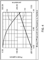
- the diffractive/refractive surface (i.e., Surface ID 10) of the hybrid lens B is can have characteristics as shown in FIG. 4 , which indicates how phase and line frequency change with radius/distance from the center of the aperture.
- the curve 102 indicates the change in phase
- the curve 104 indicates the change in line frequency.
- the diffraction order of the hybrid diffractive/refractive surfaces described above is equal to four, in other implementations the diffraction order can be equal to one or another value. In general, the diffraction order may depend on the ease of manufacturing and/or the diameter of the hybrid diffractive/refractive lens B.
- the computer modeling assumed that the index data is relative to air at the system temperature and pressure and that wavelengths are measured in air at the system temperature and pressure.
- the absolute air index values were 1.000270 at 20°C, 1.000237 at 60°C, and 1.000212 at 100°C.
- the described implementations can be additionally described in terms of an aspect ratio where the aspect ratio is defined as the largest diameter optical surface divided by the total track length of the hybrid optical assembly.
- the aspect ratio of the hybrid optical assembly can be 0.5, while in other implementations that aspect ratio can be larger or smaller depending on the intended application of the hybrid optical assembly.
- the aspect ratio can be about 0.356, while for some other implementations with a total track length of about 6.356 the aspect ratio can be about 0.224.
- the optical assembly 22 can be integrated as part of an optical pattern generator arranged to project an array or other pattern of dots onto a projection plane 36. As illustrated in the graphs of FIGS. 5A , 5B and 5C based on computer modeling, the optical assembly 22 can be used to project a high-quality array of dots onto the projection plane.
- each curve e.g., 202, 204 represents a different field point, for example, a projected dot from the VCSEL array 22.
- the values above the top of the graph i.e., 0.000mm - 0.550 mm
- FIG. 5A illustrates the curves at 20°C
- FIG. 5B illustrates the curves at 60°C
- FIG. 5C illustrates the curves at 100°C.
- Each curve in FIGS. 5A - 5C indicates the fraction of the optical energy enclosed within a centroid having a given radius from the center of the dot projected onto the plane 36.
- the steepness of the slopes of the curves out to a radius of about 3.5 ⁇ m is indicative of the high quality of the projected dots (i.e., most of the optical energy for each dot is contained within a centroid having a radius of about 3.5 ⁇ m). Further, the high quality of the projected array of dots substantially is maintained over the temperature range of 20°C - 100°C.
- the quality of the output of the athermal optical assembly 20 is substantially constant over the operating range 20°C to 100°C.
- high quality system performance can be achieved even as the temperature varies.
Landscapes
- Physics & Mathematics (AREA)
- General Physics & Mathematics (AREA)
- Optics & Photonics (AREA)
- Lenses (AREA)
- Diffracting Gratings Or Hologram Optical Elements (AREA)
- Semiconductor Lasers (AREA)
Applications Claiming Priority (2)
| Application Number | Priority Date | Filing Date | Title |
|---|---|---|---|
| US201562245082P | 2015-10-22 | 2015-10-22 | |
| PCT/SG2016/050512 WO2017069705A1 (en) | 2015-10-22 | 2016-10-21 | Athermal optical assembly |
Publications (3)
| Publication Number | Publication Date |
|---|---|
| EP3365719A1 EP3365719A1 (en) | 2018-08-29 |
| EP3365719A4 EP3365719A4 (en) | 2019-06-26 |
| EP3365719B1 true EP3365719B1 (en) | 2022-11-30 |
Family
ID=58557499
Family Applications (1)
| Application Number | Title | Priority Date | Filing Date |
|---|---|---|---|
| EP16857899.5A Active EP3365719B1 (en) | 2015-10-22 | 2016-10-21 | Athermal optical assembly |
Country Status (7)
| Country | Link |
|---|---|
| US (1) | US11073677B2 (enExample) |
| EP (1) | EP3365719B1 (enExample) |
| JP (1) | JP6952030B2 (enExample) |
| KR (1) | KR102765501B1 (enExample) |
| CN (1) | CN108292026B (enExample) |
| TW (1) | TWI700517B (enExample) |
| WO (1) | WO2017069705A1 (enExample) |
Families Citing this family (3)
| Publication number | Priority date | Publication date | Assignee | Title |
|---|---|---|---|---|
| CN114002811B (zh) | 2017-11-03 | 2024-10-01 | 玉晶光电(厦门)有限公司 | 光学透镜组 |
| CN110471192B (zh) * | 2018-05-11 | 2021-09-21 | 宁波舜宇光电信息有限公司 | 投射装置和衍射光学组件及其制造方法以及带有投射装置的电子设备 |
| US11067877B2 (en) | 2018-11-09 | 2021-07-20 | Samsung Electronics Co., Ltd. | Structured light projector and electronic device including the same |
Family Cites Families (24)
| Publication number | Priority date | Publication date | Assignee | Title |
|---|---|---|---|---|
| GB9013011D0 (en) | 1990-06-11 | 1990-10-17 | Bae Plc | Hybrid petzval objective |
| US20030043463A1 (en) | 1992-03-30 | 2003-03-06 | Yajun Li | Athermalized plastic lens |
| JPH0943508A (ja) * | 1995-07-28 | 1997-02-14 | Topcon Corp | ハイブリッドレンズ |
| US5745289A (en) * | 1996-06-21 | 1998-04-28 | Eastman Kodak Company | Athermalized diffractive optical elements |
| US5963375A (en) * | 1996-01-31 | 1999-10-05 | U.S. Precision Lens Inc. | Athermal LCD projection lens |
| DE69726352T2 (de) * | 1996-08-16 | 2004-09-09 | 3M Innovative Properties Co., St. Paul | Miniaturprojektionszoomobjektiv zur Verwendung mit Anzeigetafel mit Pixelmatrix |
| JP3720187B2 (ja) * | 1998-02-23 | 2005-11-24 | 株式会社リコー | レンズ |
| JP3686253B2 (ja) * | 1998-04-10 | 2005-08-24 | オリンパス株式会社 | 回折光学素子を用いたズームレンズ |
| US6262844B1 (en) | 1998-08-28 | 2001-07-17 | Ksm Associates, Inc. | Optical systems employing stepped diffractive surfaces |
| EP1075150A3 (en) * | 1999-07-31 | 2005-04-27 | Lg Electronics Inc. | Projection lens system |
| JP3634736B2 (ja) * | 2000-10-12 | 2005-03-30 | ペンタックス株式会社 | 光ヘッド用対物レンズおよび光ヘッドの光学系 |
| JP2002350973A (ja) | 2001-05-23 | 2002-12-04 | Kanto Auto Works Ltd | プロジェクタ |
| CN1213323C (zh) * | 2002-04-29 | 2005-08-03 | 南开大学 | 红外折射衍射三片式减热差光学成像系统结构 |
| JP2004126393A (ja) * | 2002-10-04 | 2004-04-22 | Nikon Corp | 撮像レンズ及びそれを用いた送受信装置 |
| KR20040061658A (ko) | 2002-12-31 | 2004-07-07 | 삼성전자주식회사 | 하이브리드 애크로매틱 광학 렌즈 및 그 제조방법 |
| KR100665176B1 (ko) * | 2005-05-18 | 2007-01-09 | 삼성전기주식회사 | 웨이퍼 스케일 렌즈 및 이를 구비하는 광학계 |
| JP2008077728A (ja) * | 2006-09-20 | 2008-04-03 | Canon Inc | 対物レンズ及びそれを用いた光ピックアップ装置 |
| JPWO2008102773A1 (ja) * | 2007-02-19 | 2010-05-27 | コニカミノルタオプト株式会社 | 撮像レンズ、撮像装置、携帯端末、および撮像レンズの製造方法 |
| EP2118701A1 (en) * | 2007-03-15 | 2009-11-18 | Swiss Medical Technology Gmbh | Magnification loupe with aspherical lenses |
| US8610823B2 (en) * | 2007-12-19 | 2013-12-17 | Heptagon Micro Optics Pte. Ltd. | Optical module for a camera device, baffle substrate, wafer scale package, and manufacturing methods therefor |
| WO2011043023A1 (ja) * | 2009-10-06 | 2011-04-14 | ソニー株式会社 | 光学ユニットおよび撮像装置 |
| WO2011136138A1 (ja) * | 2010-04-27 | 2011-11-03 | コニカミノルタオプト株式会社 | 撮像用レンズ、ウエハレンズ、ウエハレンズ積層体、撮像用レンズの製造方法、撮像用レンズの中間物、撮像用レンズの中間物の製造方法 |
| JP2012103461A (ja) * | 2010-11-10 | 2012-05-31 | Topcon Corp | 赤外線光学系 |
| US9094593B2 (en) | 2013-07-30 | 2015-07-28 | Heptagon Micro Optics Pte. Ltd. | Optoelectronic modules that have shielding to reduce light leakage or stray light, and fabrication methods for such modules |
-
2016
- 2016-10-21 CN CN201680068032.2A patent/CN108292026B/zh active Active
- 2016-10-21 US US15/769,916 patent/US11073677B2/en active Active
- 2016-10-21 KR KR1020187014074A patent/KR102765501B1/ko active Active
- 2016-10-21 JP JP2018520581A patent/JP6952030B2/ja active Active
- 2016-10-21 WO PCT/SG2016/050512 patent/WO2017069705A1/en not_active Ceased
- 2016-10-21 TW TW105134196A patent/TWI700517B/zh active
- 2016-10-21 EP EP16857899.5A patent/EP3365719B1/en active Active
Also Published As
| Publication number | Publication date |
|---|---|
| EP3365719A4 (en) | 2019-06-26 |
| TWI700517B (zh) | 2020-08-01 |
| JP2018531430A (ja) | 2018-10-25 |
| JP6952030B2 (ja) | 2021-10-20 |
| KR102765501B1 (ko) | 2025-02-13 |
| US20200064584A1 (en) | 2020-02-27 |
| US11073677B2 (en) | 2021-07-27 |
| CN108292026B (zh) | 2021-11-26 |
| CN108292026A (zh) | 2018-07-17 |
| TW201732322A (zh) | 2017-09-16 |
| KR20180070669A (ko) | 2018-06-26 |
| WO2017069705A1 (en) | 2017-04-27 |
| EP3365719A1 (en) | 2018-08-29 |
Similar Documents
| Publication | Publication Date | Title |
|---|---|---|
| US12578547B2 (en) | Optical lens assembly configured for near infrared light | |
| CN107505689B (zh) | 投影镜头系统 | |
| US20190219827A1 (en) | Near-eye display system | |
| CN109557650B (zh) | 准直镜头及投影模组 | |
| US20250004286A1 (en) | Optical element and optical system | |
| US20170074481A1 (en) | Microlens array and optical system including the same | |
| CN108318996B (zh) | 准直镜头 | |
| JP7253612B2 (ja) | 光線場をコリメートするための装置 | |
| CN108227149B (zh) | 准直镜头 | |
| US10409070B2 (en) | Virtual image display apparatus | |
| US20160223823A1 (en) | Apparatus of structured light generation | |
| KR20220162173A (ko) | 시선 추적 촬영에서의 광학 결합기 수차 보정 | |
| CN111812828B (zh) | 红外准直镜头和红外镜头模组 | |
| EP3365719B1 (en) | Athermal optical assembly | |
| CN113189746A (zh) | 电子装置 | |
| CN105278012A (zh) | 衍射透镜以及使用了该衍射透镜的光学装置 | |
| CN111221101A (zh) | 镜片系统、投射装置、感测模组及电子装置 | |
| JP2018531430A6 (ja) | アサーマル光学アセンブリ | |
| CN110320673B (zh) | 光学模块和用于投影的方法 | |
| WO2005106566A1 (ja) | ビーム整形光学系およびレーザービームプリンタの光学系 | |
| US20180292662A1 (en) | Rectangular beam shaper having monolithic body of refractive material | |
| CN215117017U (zh) | 一种投影模组、深度相机及电子设备 | |
| CN114924393A (zh) | 红外投影镜头 | |
| TWI708961B (zh) | 用於三維數據採集之照明組件 | |
| WO2023218924A1 (ja) | 細径ビーム生成装置 |
Legal Events
| Date | Code | Title | Description |
|---|---|---|---|
| STAA | Information on the status of an ep patent application or granted ep patent |
Free format text: STATUS: THE INTERNATIONAL PUBLICATION HAS BEEN MADE |
|
| PUAI | Public reference made under article 153(3) epc to a published international application that has entered the european phase |
Free format text: ORIGINAL CODE: 0009012 |
|
| STAA | Information on the status of an ep patent application or granted ep patent |
Free format text: STATUS: REQUEST FOR EXAMINATION WAS MADE |
|
| 17P | Request for examination filed |
Effective date: 20180517 |
|
| AK | Designated contracting states |
Kind code of ref document: A1 Designated state(s): AL AT BE BG CH CY CZ DE DK EE ES FI FR GB GR HR HU IE IS IT LI LT LU LV MC MK MT NL NO PL PT RO RS SE SI SK SM TR |
|
| AX | Request for extension of the european patent |
Extension state: BA ME |
|
| DAV | Request for validation of the european patent (deleted) | ||
| DAX | Request for extension of the european patent (deleted) | ||
| STAA | Information on the status of an ep patent application or granted ep patent |
Free format text: STATUS: EXAMINATION IS IN PROGRESS |
|
| A4 | Supplementary search report drawn up and despatched |
Effective date: 20190529 |
|
| RIC1 | Information provided on ipc code assigned before grant |
Ipc: G02B 5/18 20060101ALI20190523BHEP Ipc: G02B 27/00 20060101AFI20190523BHEP Ipc: G02B 7/00 20060101ALI20190523BHEP |
|
| 17Q | First examination report despatched |
Effective date: 20190613 |
|
| REG | Reference to a national code |
Ref country code: DE Ref legal event code: R079 Ref document number: 602016076675 Country of ref document: DE Free format text: PREVIOUS MAIN CLASS: G02B0013180000 Ipc: G02B0027000000 |
|
| GRAP | Despatch of communication of intention to grant a patent |
Free format text: ORIGINAL CODE: EPIDOSNIGR1 |
|
| STAA | Information on the status of an ep patent application or granted ep patent |
Free format text: STATUS: GRANT OF PATENT IS INTENDED |
|
| RIC1 | Information provided on ipc code assigned before grant |
Ipc: G02B 27/42 20060101ALI20220603BHEP Ipc: G02B 5/18 20060101ALI20220603BHEP Ipc: G02B 7/00 20060101ALI20220603BHEP Ipc: G02B 27/00 20060101AFI20220603BHEP |
|
| INTG | Intention to grant announced |
Effective date: 20220628 |
|
| GRAS | Grant fee paid |
Free format text: ORIGINAL CODE: EPIDOSNIGR3 |
|
| GRAA | (expected) grant |
Free format text: ORIGINAL CODE: 0009210 |
|
| STAA | Information on the status of an ep patent application or granted ep patent |
Free format text: STATUS: THE PATENT HAS BEEN GRANTED |
|
| AK | Designated contracting states |
Kind code of ref document: B1 Designated state(s): AL AT BE BG CH CY CZ DE DK EE ES FI FR GB GR HR HU IE IS IT LI LT LU LV MC MK MT NL NO PL PT RO RS SE SI SK SM TR |
|
| REG | Reference to a national code |
Ref country code: CH Ref legal event code: EP Ref country code: GB Ref legal event code: FG4D |
|
| REG | Reference to a national code |
Ref country code: AT Ref legal event code: REF Ref document number: 1535101 Country of ref document: AT Kind code of ref document: T Effective date: 20221215 |
|
| REG | Reference to a national code |
Ref country code: IE Ref legal event code: FG4D |
|
| REG | Reference to a national code |
Ref country code: DE Ref legal event code: R096 Ref document number: 602016076675 Country of ref document: DE |
|
| REG | Reference to a national code |
Ref country code: LT Ref legal event code: MG9D |
|
| REG | Reference to a national code |
Ref country code: NL Ref legal event code: MP Effective date: 20221130 |
|
| PG25 | Lapsed in a contracting state [announced via postgrant information from national office to epo] |
Ref country code: SE Free format text: LAPSE BECAUSE OF FAILURE TO SUBMIT A TRANSLATION OF THE DESCRIPTION OR TO PAY THE FEE WITHIN THE PRESCRIBED TIME-LIMIT Effective date: 20221130 Ref country code: PT Free format text: LAPSE BECAUSE OF FAILURE TO SUBMIT A TRANSLATION OF THE DESCRIPTION OR TO PAY THE FEE WITHIN THE PRESCRIBED TIME-LIMIT Effective date: 20230331 Ref country code: NO Free format text: LAPSE BECAUSE OF FAILURE TO SUBMIT A TRANSLATION OF THE DESCRIPTION OR TO PAY THE FEE WITHIN THE PRESCRIBED TIME-LIMIT Effective date: 20230228 Ref country code: LT Free format text: LAPSE BECAUSE OF FAILURE TO SUBMIT A TRANSLATION OF THE DESCRIPTION OR TO PAY THE FEE WITHIN THE PRESCRIBED TIME-LIMIT Effective date: 20221130 Ref country code: FI Free format text: LAPSE BECAUSE OF FAILURE TO SUBMIT A TRANSLATION OF THE DESCRIPTION OR TO PAY THE FEE WITHIN THE PRESCRIBED TIME-LIMIT Effective date: 20221130 Ref country code: ES Free format text: LAPSE BECAUSE OF FAILURE TO SUBMIT A TRANSLATION OF THE DESCRIPTION OR TO PAY THE FEE WITHIN THE PRESCRIBED TIME-LIMIT Effective date: 20221130 |
|
| REG | Reference to a national code |
Ref country code: AT Ref legal event code: MK05 Ref document number: 1535101 Country of ref document: AT Kind code of ref document: T Effective date: 20221130 |
|
| PG25 | Lapsed in a contracting state [announced via postgrant information from national office to epo] |
Ref country code: RS Free format text: LAPSE BECAUSE OF FAILURE TO SUBMIT A TRANSLATION OF THE DESCRIPTION OR TO PAY THE FEE WITHIN THE PRESCRIBED TIME-LIMIT Effective date: 20221130 Ref country code: PL Free format text: LAPSE BECAUSE OF FAILURE TO SUBMIT A TRANSLATION OF THE DESCRIPTION OR TO PAY THE FEE WITHIN THE PRESCRIBED TIME-LIMIT Effective date: 20221130 Ref country code: LV Free format text: LAPSE BECAUSE OF FAILURE TO SUBMIT A TRANSLATION OF THE DESCRIPTION OR TO PAY THE FEE WITHIN THE PRESCRIBED TIME-LIMIT Effective date: 20221130 Ref country code: IS Free format text: LAPSE BECAUSE OF FAILURE TO SUBMIT A TRANSLATION OF THE DESCRIPTION OR TO PAY THE FEE WITHIN THE PRESCRIBED TIME-LIMIT Effective date: 20230330 Ref country code: HR Free format text: LAPSE BECAUSE OF FAILURE TO SUBMIT A TRANSLATION OF THE DESCRIPTION OR TO PAY THE FEE WITHIN THE PRESCRIBED TIME-LIMIT Effective date: 20221130 Ref country code: GR Free format text: LAPSE BECAUSE OF FAILURE TO SUBMIT A TRANSLATION OF THE DESCRIPTION OR TO PAY THE FEE WITHIN THE PRESCRIBED TIME-LIMIT Effective date: 20230301 |
|
| PG25 | Lapsed in a contracting state [announced via postgrant information from national office to epo] |
Ref country code: NL Free format text: LAPSE BECAUSE OF FAILURE TO SUBMIT A TRANSLATION OF THE DESCRIPTION OR TO PAY THE FEE WITHIN THE PRESCRIBED TIME-LIMIT Effective date: 20221130 |
|
| PG25 | Lapsed in a contracting state [announced via postgrant information from national office to epo] |
Ref country code: SM Free format text: LAPSE BECAUSE OF FAILURE TO SUBMIT A TRANSLATION OF THE DESCRIPTION OR TO PAY THE FEE WITHIN THE PRESCRIBED TIME-LIMIT Effective date: 20221130 Ref country code: RO Free format text: LAPSE BECAUSE OF FAILURE TO SUBMIT A TRANSLATION OF THE DESCRIPTION OR TO PAY THE FEE WITHIN THE PRESCRIBED TIME-LIMIT Effective date: 20221130 Ref country code: EE Free format text: LAPSE BECAUSE OF FAILURE TO SUBMIT A TRANSLATION OF THE DESCRIPTION OR TO PAY THE FEE WITHIN THE PRESCRIBED TIME-LIMIT Effective date: 20221130 Ref country code: DK Free format text: LAPSE BECAUSE OF FAILURE TO SUBMIT A TRANSLATION OF THE DESCRIPTION OR TO PAY THE FEE WITHIN THE PRESCRIBED TIME-LIMIT Effective date: 20221130 Ref country code: CZ Free format text: LAPSE BECAUSE OF FAILURE TO SUBMIT A TRANSLATION OF THE DESCRIPTION OR TO PAY THE FEE WITHIN THE PRESCRIBED TIME-LIMIT Effective date: 20221130 Ref country code: AT Free format text: LAPSE BECAUSE OF FAILURE TO SUBMIT A TRANSLATION OF THE DESCRIPTION OR TO PAY THE FEE WITHIN THE PRESCRIBED TIME-LIMIT Effective date: 20221130 |
|
| PG25 | Lapsed in a contracting state [announced via postgrant information from national office to epo] |
Ref country code: SK Free format text: LAPSE BECAUSE OF FAILURE TO SUBMIT A TRANSLATION OF THE DESCRIPTION OR TO PAY THE FEE WITHIN THE PRESCRIBED TIME-LIMIT Effective date: 20221130 Ref country code: AL Free format text: LAPSE BECAUSE OF FAILURE TO SUBMIT A TRANSLATION OF THE DESCRIPTION OR TO PAY THE FEE WITHIN THE PRESCRIBED TIME-LIMIT Effective date: 20221130 |
|
| REG | Reference to a national code |
Ref country code: DE Ref legal event code: R097 Ref document number: 602016076675 Country of ref document: DE |
|
| P01 | Opt-out of the competence of the unified patent court (upc) registered |
Effective date: 20230825 |
|
| PLBE | No opposition filed within time limit |
Free format text: ORIGINAL CODE: 0009261 |
|
| STAA | Information on the status of an ep patent application or granted ep patent |
Free format text: STATUS: NO OPPOSITION FILED WITHIN TIME LIMIT |
|
| 26N | No opposition filed |
Effective date: 20230831 |
|
| PG25 | Lapsed in a contracting state [announced via postgrant information from national office to epo] |
Ref country code: SI Free format text: LAPSE BECAUSE OF FAILURE TO SUBMIT A TRANSLATION OF THE DESCRIPTION OR TO PAY THE FEE WITHIN THE PRESCRIBED TIME-LIMIT Effective date: 20221130 |
|
| PG25 | Lapsed in a contracting state [announced via postgrant information from national office to epo] |
Ref country code: IT Free format text: LAPSE BECAUSE OF FAILURE TO SUBMIT A TRANSLATION OF THE DESCRIPTION OR TO PAY THE FEE WITHIN THE PRESCRIBED TIME-LIMIT Effective date: 20221130 Ref country code: MC Free format text: LAPSE BECAUSE OF FAILURE TO SUBMIT A TRANSLATION OF THE DESCRIPTION OR TO PAY THE FEE WITHIN THE PRESCRIBED TIME-LIMIT Effective date: 20221130 |
|
| REG | Reference to a national code |
Ref country code: CH Ref legal event code: PL |
|
| REG | Reference to a national code |
Ref country code: BE Ref legal event code: MM Effective date: 20231031 |
|
| PG25 | Lapsed in a contracting state [announced via postgrant information from national office to epo] |
Ref country code: LU Free format text: LAPSE BECAUSE OF NON-PAYMENT OF DUE FEES Effective date: 20231021 |
|
| GBPC | Gb: european patent ceased through non-payment of renewal fee |
Effective date: 20231021 |
|
| PG25 | Lapsed in a contracting state [announced via postgrant information from national office to epo] |
Ref country code: LU Free format text: LAPSE BECAUSE OF NON-PAYMENT OF DUE FEES Effective date: 20231021 |
|
| PG25 | Lapsed in a contracting state [announced via postgrant information from national office to epo] |
Ref country code: GB Free format text: LAPSE BECAUSE OF NON-PAYMENT OF DUE FEES Effective date: 20231021 |
|
| PG25 | Lapsed in a contracting state [announced via postgrant information from national office to epo] |
Ref country code: CH Free format text: LAPSE BECAUSE OF NON-PAYMENT OF DUE FEES Effective date: 20231031 |
|
| PG25 | Lapsed in a contracting state [announced via postgrant information from national office to epo] |
Ref country code: GB Free format text: LAPSE BECAUSE OF NON-PAYMENT OF DUE FEES Effective date: 20231021 Ref country code: CH Free format text: LAPSE BECAUSE OF NON-PAYMENT OF DUE FEES Effective date: 20231031 |
|
| PG25 | Lapsed in a contracting state [announced via postgrant information from national office to epo] |
Ref country code: BE Free format text: LAPSE BECAUSE OF NON-PAYMENT OF DUE FEES Effective date: 20231031 |
|
| REG | Reference to a national code |
Ref country code: DE Ref legal event code: R081 Ref document number: 602016076675 Country of ref document: DE Owner name: AMS-OSRAM ASIA PACIFIC PTE. LTD., SG Free format text: FORMER OWNER: HEPTAGON MICRO OPTICS PTE. LTD., SINGAPORE, SG |
|
| PG25 | Lapsed in a contracting state [announced via postgrant information from national office to epo] |
Ref country code: IE Free format text: LAPSE BECAUSE OF NON-PAYMENT OF DUE FEES Effective date: 20231021 |
|
| PG25 | Lapsed in a contracting state [announced via postgrant information from national office to epo] |
Ref country code: IE Free format text: LAPSE BECAUSE OF NON-PAYMENT OF DUE FEES Effective date: 20231021 |
|
| PG25 | Lapsed in a contracting state [announced via postgrant information from national office to epo] |
Ref country code: BG Free format text: LAPSE BECAUSE OF FAILURE TO SUBMIT A TRANSLATION OF THE DESCRIPTION OR TO PAY THE FEE WITHIN THE PRESCRIBED TIME-LIMIT Effective date: 20221130 |
|
| PG25 | Lapsed in a contracting state [announced via postgrant information from national office to epo] |
Ref country code: BG Free format text: LAPSE BECAUSE OF FAILURE TO SUBMIT A TRANSLATION OF THE DESCRIPTION OR TO PAY THE FEE WITHIN THE PRESCRIBED TIME-LIMIT Effective date: 20221130 |
|
| PG25 | Lapsed in a contracting state [announced via postgrant information from national office to epo] |
Ref country code: CY Free format text: LAPSE BECAUSE OF FAILURE TO SUBMIT A TRANSLATION OF THE DESCRIPTION OR TO PAY THE FEE WITHIN THE PRESCRIBED TIME-LIMIT; INVALID AB INITIO Effective date: 20161021 |
|
| PG25 | Lapsed in a contracting state [announced via postgrant information from national office to epo] |
Ref country code: HU Free format text: LAPSE BECAUSE OF FAILURE TO SUBMIT A TRANSLATION OF THE DESCRIPTION OR TO PAY THE FEE WITHIN THE PRESCRIBED TIME-LIMIT; INVALID AB INITIO Effective date: 20161021 |
|
| PG25 | Lapsed in a contracting state [announced via postgrant information from national office to epo] |
Ref country code: TR Free format text: LAPSE BECAUSE OF FAILURE TO SUBMIT A TRANSLATION OF THE DESCRIPTION OR TO PAY THE FEE WITHIN THE PRESCRIBED TIME-LIMIT Effective date: 20221130 |
|
| PGFP | Annual fee paid to national office [announced via postgrant information from national office to epo] |
Ref country code: DE Payment date: 20251021 Year of fee payment: 10 |
|
| PGFP | Annual fee paid to national office [announced via postgrant information from national office to epo] |
Ref country code: FR Payment date: 20251030 Year of fee payment: 10 |