EP3365492B1 - High-strength fiber rope for lifting devices such as cranes - Google Patents
High-strength fiber rope for lifting devices such as cranes Download PDFInfo
- Publication number
- EP3365492B1 EP3365492B1 EP16784209.5A EP16784209A EP3365492B1 EP 3365492 B1 EP3365492 B1 EP 3365492B1 EP 16784209 A EP16784209 A EP 16784209A EP 3365492 B1 EP3365492 B1 EP 3365492B1
- Authority
- EP
- European Patent Office
- Prior art keywords
- rope
- strength
- sheath
- layer
- different
- Prior art date
- Legal status (The legal status is an assumption and is not a legal conclusion. Google has not performed a legal analysis and makes no representation as to the accuracy of the status listed.)
- Active
Links
- 239000000835 fiber Substances 0.000 title claims description 82
- 229920002994 synthetic fiber Polymers 0.000 claims description 24
- 239000003086 colorant Substances 0.000 claims description 9
- 239000000463 material Substances 0.000 claims description 9
- 238000005452 bending Methods 0.000 claims description 7
- 229920000785 ultra high molecular weight polyethylene Polymers 0.000 claims description 5
- 229920000728 polyester Polymers 0.000 claims description 2
- WJXQFVMTIGJBFX-UHFFFAOYSA-N 4-methoxytyramine Chemical compound COC1=CC=C(CCN)C=C1O WJXQFVMTIGJBFX-UHFFFAOYSA-N 0.000 claims 1
- 239000000725 suspension Substances 0.000 claims 1
- 238000005253 cladding Methods 0.000 description 19
- 229920003023 plastic Polymers 0.000 description 15
- 239000004033 plastic Substances 0.000 description 15
- 239000012209 synthetic fiber Substances 0.000 description 15
- 238000005299 abrasion Methods 0.000 description 13
- 230000008093 supporting effect Effects 0.000 description 7
- 229910000831 Steel Inorganic materials 0.000 description 5
- 239000010959 steel Substances 0.000 description 5
- 208000025962 Crush injury Diseases 0.000 description 4
- 208000034656 Contusions Diseases 0.000 description 3
- 208000034526 bruise Diseases 0.000 description 3
- 229920000049 Carbon (fiber) Polymers 0.000 description 2
- 239000004760 aramid Substances 0.000 description 2
- 229920006231 aramid fiber Polymers 0.000 description 2
- 230000008901 benefit Effects 0.000 description 2
- 239000004917 carbon fiber Substances 0.000 description 2
- 238000011161 development Methods 0.000 description 2
- 230000018109 developmental process Effects 0.000 description 2
- 238000005259 measurement Methods 0.000 description 2
- 238000000034 method Methods 0.000 description 2
- 230000009467 reduction Effects 0.000 description 2
- 238000004804 winding Methods 0.000 description 2
- VSSAADCISISCOY-UHFFFAOYSA-N 1-(4-furo[3,4-c]pyridin-1-ylphenyl)furo[3,4-c]pyridine Chemical compound C1=CN=CC2=COC(C=3C=CC(=CC=3)C3=C4C=CN=CC4=CO3)=C21 VSSAADCISISCOY-UHFFFAOYSA-N 0.000 description 1
- VHSHLMUCYSAUQU-UHFFFAOYSA-N 2-hydroxypropyl methacrylate Chemical compound CC(O)COC(=O)C(C)=C VHSHLMUCYSAUQU-UHFFFAOYSA-N 0.000 description 1
- 238000013459 approach Methods 0.000 description 1
- 238000004040 coloring Methods 0.000 description 1
- 230000001419 dependent effect Effects 0.000 description 1
- 238000013461 design Methods 0.000 description 1
- 229910003460 diamond Inorganic materials 0.000 description 1
- 239000010432 diamond Substances 0.000 description 1
- 238000005516 engineering process Methods 0.000 description 1
- 238000011156 evaluation Methods 0.000 description 1
- 239000003302 ferromagnetic material Substances 0.000 description 1
- GNOIPBMMFNIUFM-UHFFFAOYSA-N hexamethylphosphoric triamide Chemical compound CN(C)P(=O)(N(C)C)N(C)C GNOIPBMMFNIUFM-UHFFFAOYSA-N 0.000 description 1
- 238000005461 lubrication Methods 0.000 description 1
- 230000007246 mechanism Effects 0.000 description 1
- VNWKTOKETHGBQD-UHFFFAOYSA-N methane Chemical compound C VNWKTOKETHGBQD-UHFFFAOYSA-N 0.000 description 1
- 239000000203 mixture Substances 0.000 description 1
- 230000007480 spreading Effects 0.000 description 1
- 238000003892 spreading Methods 0.000 description 1
- 238000010998 test method Methods 0.000 description 1
- 238000012360 testing method Methods 0.000 description 1
- 230000008719 thickening Effects 0.000 description 1
- 230000000007 visual effect Effects 0.000 description 1
- 238000011179 visual inspection Methods 0.000 description 1
- 239000013585 weight reducing agent Substances 0.000 description 1
Images


Classifications
-
- D—TEXTILES; PAPER
- D07—ROPES; CABLES OTHER THAN ELECTRIC
- D07B—ROPES OR CABLES IN GENERAL
- D07B1/00—Constructional features of ropes or cables
- D07B1/14—Ropes or cables with incorporated auxiliary elements, e.g. for marking, extending throughout the length of the rope or cable
- D07B1/145—Ropes or cables with incorporated auxiliary elements, e.g. for marking, extending throughout the length of the rope or cable comprising elements for indicating or detecting the rope or cable status
-
- B—PERFORMING OPERATIONS; TRANSPORTING
- B66—HOISTING; LIFTING; HAULING
- B66B—ELEVATORS; ESCALATORS OR MOVING WALKWAYS
- B66B7/00—Other common features of elevators
- B66B7/12—Checking, lubricating, or cleaning means for ropes, cables or guides
- B66B7/1207—Checking means
- B66B7/1215—Checking means specially adapted for ropes or cables
- B66B7/1238—Checking means specially adapted for ropes or cables by optical techniques
-
- B—PERFORMING OPERATIONS; TRANSPORTING
- B66—HOISTING; LIFTING; HAULING
- B66C—CRANES; LOAD-ENGAGING ELEMENTS OR DEVICES FOR CRANES, CAPSTANS, WINCHES, OR TACKLES
- B66C15/00—Safety gear
-
- B—PERFORMING OPERATIONS; TRANSPORTING
- B66—HOISTING; LIFTING; HAULING
- B66C—CRANES; LOAD-ENGAGING ELEMENTS OR DEVICES FOR CRANES, CAPSTANS, WINCHES, OR TACKLES
- B66C23/00—Cranes comprising essentially a beam, boom, or triangular structure acting as a cantilever and mounted for translatory of swinging movements in vertical or horizontal planes or a combination of such movements, e.g. jib-cranes, derricks, tower cranes
- B66C23/16—Cranes comprising essentially a beam, boom, or triangular structure acting as a cantilever and mounted for translatory of swinging movements in vertical or horizontal planes or a combination of such movements, e.g. jib-cranes, derricks, tower cranes with jibs supported by columns, e.g. towers having their lower end mounted for slewing movements
-
- B—PERFORMING OPERATIONS; TRANSPORTING
- B66—HOISTING; LIFTING; HAULING
- B66D—CAPSTANS; WINCHES; TACKLES, e.g. PULLEY BLOCKS; HOISTS
- B66D1/00—Rope, cable, or chain winding mechanisms; Capstans
- B66D1/54—Safety gear
-
- D—TEXTILES; PAPER
- D07—ROPES; CABLES OTHER THAN ELECTRIC
- D07B—ROPES OR CABLES IN GENERAL
- D07B1/00—Constructional features of ropes or cables
- D07B1/02—Ropes built-up from fibrous or filamentary material, e.g. of vegetable origin, of animal origin, regenerated cellulose, plastics
- D07B1/04—Ropes built-up from fibrous or filamentary material, e.g. of vegetable origin, of animal origin, regenerated cellulose, plastics with a core of fibres or filaments arranged parallel to the centre line
-
- D—TEXTILES; PAPER
- D07—ROPES; CABLES OTHER THAN ELECTRIC
- D07B—ROPES OR CABLES IN GENERAL
- D07B1/00—Constructional features of ropes or cables
- D07B1/14—Ropes or cables with incorporated auxiliary elements, e.g. for marking, extending throughout the length of the rope or cable
- D07B1/148—Ropes or cables with incorporated auxiliary elements, e.g. for marking, extending throughout the length of the rope or cable comprising marks or luminous elements
-
- D—TEXTILES; PAPER
- D07—ROPES; CABLES OTHER THAN ELECTRIC
- D07B—ROPES OR CABLES IN GENERAL
- D07B1/00—Constructional features of ropes or cables
- D07B1/24—Ropes or cables with a prematurely failing element
-
- G—PHYSICS
- G01—MEASURING; TESTING
- G01N—INVESTIGATING OR ANALYSING MATERIALS BY DETERMINING THEIR CHEMICAL OR PHYSICAL PROPERTIES
- G01N21/00—Investigating or analysing materials by the use of optical means, i.e. using sub-millimetre waves, infrared, visible or ultraviolet light
- G01N21/84—Systems specially adapted for particular applications
- G01N21/88—Investigating the presence of flaws or contamination
- G01N21/95—Investigating the presence of flaws or contamination characterised by the material or shape of the object to be examined
- G01N21/952—Inspecting the exterior surface of cylindrical bodies or wires
-
- D—TEXTILES; PAPER
- D07—ROPES; CABLES OTHER THAN ELECTRIC
- D07B—ROPES OR CABLES IN GENERAL
- D07B1/00—Constructional features of ropes or cables
- D07B1/02—Ropes built-up from fibrous or filamentary material, e.g. of vegetable origin, of animal origin, regenerated cellulose, plastics
- D07B1/025—Ropes built-up from fibrous or filamentary material, e.g. of vegetable origin, of animal origin, regenerated cellulose, plastics comprising high modulus, or high tenacity, polymer filaments or fibres, e.g. liquid-crystal polymers
-
- D—TEXTILES; PAPER
- D07—ROPES; CABLES OTHER THAN ELECTRIC
- D07B—ROPES OR CABLES IN GENERAL
- D07B2201/00—Ropes or cables
- D07B2201/20—Rope or cable components
- D07B2201/2083—Jackets or coverings
- D07B2201/2088—Jackets or coverings having multiple layers
-
- D—TEXTILES; PAPER
- D07—ROPES; CABLES OTHER THAN ELECTRIC
- D07B—ROPES OR CABLES IN GENERAL
- D07B2201/00—Ropes or cables
- D07B2201/20—Rope or cable components
- D07B2201/2083—Jackets or coverings
- D07B2201/209—Jackets or coverings comprising braided structures
-
- D—TEXTILES; PAPER
- D07—ROPES; CABLES OTHER THAN ELECTRIC
- D07B—ROPES OR CABLES IN GENERAL
- D07B2201/00—Ropes or cables
- D07B2201/20—Rope or cable components
- D07B2201/2083—Jackets or coverings
- D07B2201/2092—Jackets or coverings characterised by the materials used
-
- D—TEXTILES; PAPER
- D07—ROPES; CABLES OTHER THAN ELECTRIC
- D07B—ROPES OR CABLES IN GENERAL
- D07B2501/00—Application field
- D07B2501/20—Application field related to ropes or cables
- D07B2501/2015—Construction industries
Definitions
- the present invention relates to a high-strength fiber rope for hoists such as cranes, with a rope core comprising high-strength plastic fibers and a wear-indicating sheath surrounding the rope core.
- HMPA Aramid fibers
- HMPE high-modulus polyethylene fibers
- PBO poly (p-phenylene-2,6-benzobisoxazole) fibers
- the load hook can be made lighter because less load hook weight is required to tension a fiber rope.
- rope drives with synthetic fiber ropes are characterized by a considerably longer service life, easy handling and good flexibility as well as the fact that rope lubrication is no longer necessary. Overall, greater device availability can be achieved as a result.
- High-strength fiber ropes like steel ropes, are wear parts that must be replaced when their condition has deteriorated to such an extent that the required safety is no longer provided in continued operation. This condition is generally referred to as discard maturity.
- the discard state can be determined quite simply by visually inspecting the condition of the rope, with the test procedure and the scope of the test being specified in the ISO 4309 standard. Essentially, the focus is on the number of wire breaks over a certain measuring length of the rope, a reduction in the rope diameter and broken strands.
- this measuring method is not possible for detecting the discard state of high-strength fiber ropes, since the synthetic fibers used do not behave like wire strands.
- high-strength fiber ropes often fail abruptly or the discard state occurs without gradually recognizable previous damage, since, unlike steel ropes, individual fibers often do not gradually tear and fan out, but often several fiber strands fail at the same time.
- the EP 1 930 497 A and EP 1 930 496 A disclose the use of an electrically conductive indicator fiber that has less abrasion resistance than the other strands or fibers of the rope. If the indicator fiber is damaged or tears, this can be determined by means of conductivity measurements.
- markings e.g. braided diamond shapes made of differently colored material
- markings are provided on the sheath of a core/sheath rope, by means of which one can determine elongations or twisting of the rope.
- the WO 2003/054290 A1 proposes a ferromagnetic material with which one should also be able to detect local damage to the rope.
- fibers with different stretch behavior in a rope is discussed in the DE 24 55 273 B2 and is intended to ensure that all strand layers of the rope take on the load, but not to indicate wear. It is also worth mentioning that in this disclosure, in marked contrast to the present Invention, fibers are arranged with lower strength inside the rope.
- the present invention is based on the object of creating an improved, high-strength fiber rope which avoids the disadvantages of the prior art and develops the latter in an advantageous manner.
- a simple, yet reliable and precise determination of the discard state and thus the longest possible service life should be made possible without impairing the safety of the fiber rope.
- the sheathing has a fiber structure made of different types of synthetic fibers that have different wear resistances and therefore do not all show damage at the same time, even when exposed to wear-promoting influences in a uniform manner, but rather wear out gradually.
- the sheathing has at least one cladding layer in which plastic fibers of different abrasion and/or tensile strengths and/or flexural fatigue strengths are intertwined, with the plastic fibers of different abrasion and/or tensile strengths and/or flexural fatigue strengths making it possible to visually assess the degree of damage.
- the casing has several casing layers which differ from one another in terms of their fiber structure and the abrasion resistance and/or tensile strength and/or flexural fatigue strength of the plastic fibers used in the casing layers.
- the invention thus provides at least one covering layer with plastic fibers with different wear properties.
- Other variants of the invention additionally provide multiple cladding layers each having fibers with different wear characteristics or having fibers with different wear characteristics within the respective cladding layers.
- the sheath layer which contains fibers with different wear properties, is preferably present in the outer region of the sheath, particularly preferably in the outermost layer of the rope.
- the different abrasion and/or tensile strengths and/or flexural fatigue strength of the plastic fibers used in the at least one cover layer ensures that damage to the cover layer occurs only partially and gradually, so that based on the gradually increasing damage locations, different wear states of the rope and the associated wear and tear can be identified , the remaining distance to discard can be gradually determined and quantified.
- the degree of damage is determined by visual assessment.
- the fibers of different abrasion resistance and/or tensile strength and/or flexural fatigue strength are therefore preferably present in the outer or outermost regions of the sheathing that are visible from the outside and are optically accessible.
- the shell is designed to be essentially non-load bearing.
- the plastic fibers intertwined with one another in the at least one cladding layer can advantageously consist of different materials.
- HMPE fibers and polyester fibers can be braided together in a sheath layer.
- other fibers mentioned at the outset such as PBO fibers and/or aramid-carbon fiber mixed fibers, can also be braided together or braided into the aforementioned jacket layer.
- outer layers can differ in terms of their fiber structure, e.g. from different types of synthetic fibers and the abrasion and/or tensile strength and/or flexural fatigue strength of the in or synthetic fibers used within the cover layers differ from each other.
- plastic fibers can be provided in a first, outer cladding layer, which differ from all the plastic fibers in a second, underlying cladding layer in terms of their abrasion resistance, flexural fatigue strength and/or tensile strength.
- plastic fibers of a specific abrasion and/or tensile strength can also be provided in each outer layer, which are not provided in any other outer layer, so that each outer layer shows a characteristic resistance to abrasion and fracture damage, which leads to a partially different damage pattern in each outer layer. After failure of the outer sheath, this makes it easy to distinguish ever deeper damage from one another in a simple manner.
- the synthetic fibers used in the various cladding layers can also consist of different materials, for example such that plastic fibers of a material are provided in a first cladding layer that are not present in a second cladding layer.
- the cladding layers of the sheathing can also have different layer thicknesses and/or plastic fibers and/or strands of different thicknesses can be provided from layer to layer.
- plastic fibers of different thicknesses By using plastic fibers of different thicknesses, different damage patterns can be achieved from layer to layer.
- the use of different layer thicknesses, which can increase from the outside inwards, for example, can ensure that ever deeper damage occurs more severely and initially only minor damage, which is still relatively far from the point of discard, first occurs on the outer layer and are therefore easily recognizable.
- the fibers of different abrasion resistance and/or tensile strength and/or flexural fatigue strength are preferably present at least in the outermost cladding layer.
- plastic fibers of different fiber thicknesses and/or different strand thicknesses can also be useful in a cladding layer in order to achieve partially different damage patterns in a cladding layer.
- the plastic fibers which have different abrasion, reverse bending and/or tensile strengths and/or consist of different materials, can be dyed in different colors.
- different colors can also be used from cladding layer to cladding layer or different cladding layers can be colored in different colors. This makes it much easier to visually detect damage to the casing, since when an outer casing layer wears out, the underlying casing layer becomes visible in a different color or color combination.
- the cable core can also have a different color than the sheath, in particular a different color than the bottom or innermost layer of the sheath, so that the other color of the cable core becomes visible at the latest when the sheath is completely worn out.
- the determination of the discard state can be carried out by a competent person such as the crane operator as a visual inspection based on reference representations of the rope with different degrees of damage .
- the high-strength fiber rope comprises a rope core 11, which can be braided or laid from strands 4, which in turn consist of high-strength synthetic fibers or at least include such high-strength synthetic fibers, for example HPMA fibers, HMPE fibers or other of the fiber types mentioned at the outset, the said rope core 11 can consist of fibers of one fiber type or fibers of different fiber types.
- the sheathing 2 surrounds said cable core 11 and can sit directly on said cable core or, if necessary, be spaced from it by an intermediate layer. Said casing 2 can in particular form the outer casing of the cable 1 .
- the rope core 11 can withstand the entire specified tensile strength of rope 1 take over.
- the sheathing 2 only has a supporting effect, in particular as protection for the cable core 11 and as a wear indicator.
- Said casing 2 can in this case consist of a single cladding layer or also comprise a plurality of cladding layers which are arranged one on top of the other.
- said sheathing 2 comprises strands 3 which are braided together to form sheathing 2 and can each consist of high-strength synthetic fibers or can at least have such high-strength synthetic fibers.
- the said strands 3 of the sheathing 2 can be formed in the manner described in detail at the outset from different synthetic fibers of different abrasion and tensile strengths and, if necessary, from different materials.
- said strands 3 are advantageously colored in different colors.
Description
Die vorliegende Erfindung betrifft ein hochfestes Faserseil für Hebezeuge wie Krane, mit einem Seilkern, der hochfeste Kunststofffasern umfasst, sowie einer den Seilkern umgebenden, verschleißanzeigenden Ummantelung.The present invention relates to a high-strength fiber rope for hoists such as cranes, with a rope core comprising high-strength plastic fibers and a wear-indicating sheath surrounding the rope core.
Seit geraumer Zeit wird in der Hebetechnik und insbesondere bei Kranen versucht, die üblichen, schweren Stahlseile durch hochfeste Faserseile zu ersetzen, die aus hochfesten Kunstfasern wie beispielsweise. Aramidfasern (HMPA), Aramid-/ Kohlefasergemischen, hochmodularen Polyethylenfasern (HMPE), oder Poly(p-phenylene-2,6-benzobisoxazole)-Fasern (PBO) bestehen oder zumindest derartige Fasern aufweisen. Durch die Gewichtsersparnis gegenüber Stahlseilen von bis zu 80% bei annähernd gleicher Bruchfestigkeit kann die Traglast bzw. die zulässige Hublast erhöht werden, da das für die Traglast zu berücksichtigende Eigengewicht des Seils deutlich geringer ist. Gerade bei Kranen mit großer Hubhöhe, oder in Auslegern oder Mastverstellwerken mit Flaschenzügen hoher Einscherungszahl kommen beträchtliche Seillängen und damit auch ein entsprechendes Seilgewicht zustande, sodass die durch hochfeste Faserseile mögliche Gewichtsreduzierung sehr vorteilhaft ist. Zusätzlich zum Gewichtsvorteil des Faserseiles selbst kommt hinzu, dass die Verwendung von Faserseilen auch eine Gewichtsersparnis bei weiteren Komponenten ermöglicht. Beispielsweise kann der Lasthaken leichter ausgeführt werden, da zur Seilspannung eines Faserseils weniger Lasthakengewicht notwendig ist. Zum anderen erlaubt die gute Biegsamkeit von Synthetikfaserseilen kleinere Biegeradien und damit kleinere Seilscheiben bzw. -rollen am Kran, was zu einer weiteren Gewichtsreduzierung insbesondere im Bereich von Kranauslegern führt, sodass bei großen Kranausladungen eine erhebliche Lastmomentsteigerung erreicht werden kann.For some time, attempts have been made in lifting technology, and in particular in the case of cranes, to replace the usual, heavy steel cables with high-strength fiber cables made from high-strength synthetic fibers such as, for example. Aramid fibers (HMPA), aramid / carbon fiber mixtures, high-modulus polyethylene fibers (HMPE), or poly (p-phenylene-2,6-benzobisoxazole) fibers (PBO) exist or at least have such fibers. Due to the weight savings of up to 80% compared to steel cables with almost the same breaking strength, the load capacity or the permissible lifting load can be increased, since the cable's own weight to be taken into account for the load capacity is significantly lower. Particularly in the case of cranes with a large lifting height, or in jibs or mast adjustment mechanisms with pulley blocks with a high reeving number, there are considerable rope lengths and thus a corresponding rope weight, so that the weight reduction possible with high-strength fiber ropes is very advantageous. In addition to the weight advantage of the fiber rope itself, the use of fiber ropes also enables weight savings in other components. For example, the load hook can be made lighter because less load hook weight is required to tension a fiber rope. On the other hand, the good flexibility of synthetic fiber ropes allows smaller bending radii and thus smaller rope sheaves or sheaves on the crane, which leads to a further reduction in weight, especially in the area of crane jibs, so that a considerable increase in load torque can be achieved with large crane radiuses.
Zusätzlich zu den genannten Gewichtsvorteilen zeichnen sich Seiltriebe mit Kunstfaserseilen durch eine beträchtlich größere Lebensdauer, leichtes Hantieren und gute Biegsamkeit sowie die nicht mehr notwendige Seilschmierung aus. Insgesamt kann hierdurch eine größere Geräteverfügbarkeit erzielt werden.In addition to the weight advantages mentioned, rope drives with synthetic fiber ropes are characterized by a considerably longer service life, easy handling and good flexibility as well as the fact that rope lubrication is no longer necessary. Overall, greater device availability can be achieved as a result.
Eine Schwierigkeit bei solchen hochfesten Faserseilen besteht jedoch darin, deren Ablegereife präzise und verlässlich vorherzusagen bzw. zu bestimmen. Hochfeste Faserseile sind wie Stahlseile Verschleißteile, die ausgetauscht werden müssen, wenn sich ihr Zustand soweit verschlechtert hat, dass bei weiterem Betrieb die erforderliche Sicherheit nicht mehr gegeben ist. Diesen Zustand bezeichnet man allgemein als Ablegereife.However, one difficulty with such high-strength fiber ropes is precisely and reliably predicting or determining when they are due to be discarded. High-strength fiber ropes, like steel ropes, are wear parts that must be replaced when their condition has deteriorated to such an extent that the required safety is no longer provided in continued operation. This condition is generally referred to as discard maturity.
Bei herkömmlichen Stahlseilen ist die Ablegereife in an sich recht einfacher Weise durch Inaugenscheinnahme des Seilzustandes ermittelbar, wobei die Vorgehensweise bei der Prüfung und der Prüfungsumfang in der Norm ISO 4309 vorgegeben wird. Im Wesentlichen wird dabei auf die Anzahl der Drahtbrüche über eine bestimmte Messlänge des Seiles, eine Verringerung des Seildurchmessers sowie auf Litzenbrüche abgestellt. Diese Messmethode ist jedoch zur Erkennung der Ablegereife bei hochfesten Faserseilen nicht möglich, da sich die verwendeten Synthetikfasern nicht so verhalten wie Drahtlitzen. Insbesondere kommt es bei hochfesten Faserseilen oft zu einem schlagartigen Versagen bzw. einem Eintreten der Ablegereife ohne nach und nach erkennbare Vorschädigungen, da anders als bei Stahlseilen oftmals nicht einzelne Fasern nach und nach reißen und aufspleißen, sondern oft gleichzeitig mehrere Faserstränge versagen.In the case of conventional steel ropes, the discard state can be determined quite simply by visually inspecting the condition of the rope, with the test procedure and the scope of the test being specified in the ISO 4309 standard. Essentially, the focus is on the number of wire breaks over a certain measuring length of the rope, a reduction in the rope diameter and broken strands. However, this measuring method is not possible for detecting the discard state of high-strength fiber ropes, since the synthetic fibers used do not behave like wire strands. In particular, high-strength fiber ropes often fail abruptly or the discard state occurs without gradually recognizable previous damage, since, unlike steel ropes, individual fibers often do not gradually tear and fan out, but often several fiber strands fail at the same time.
Aus der Schrift
Die
Dieser Zugang ist nachteilig, da er zusätzliche Leitfähigkeitsmessungen erfordert und damit verbunden die nötige technische Infrastruktur wie Stromquelle, Leitfähigkeitsmessgerät, Anschlussstellen für die Indikatorfaser.This approach is disadvantageous because it requires additional conductivity measurements and the associated technical infrastructure such as power source, conductivity meter, connection points for the indicator fiber.
Ebenfalls sind Verfahren bekannt, welche die Längung des Seiles über die Lebensdauer als Bewertungskriterium für den Zustand des Seiles sowie die Vorhersage der Ablegereife heranziehen und auf verschiedene Weise bestimmen, so z.B. aus der
Aus der
Weiterer Stand der Technik ist aus
Der Einsatz von Fasern mit unterschiedlichem Dehnverhalten in einem Seil wird in der
Weiter offenbart die
Der vorliegenden Erfindung liegt demgegenüber die Aufgabe zugrunde, ein verbessertes hochfestes Faserseil zu schaffen, das Nachteile des Standes der Technik vermeidet und letzteren in vorteilhafter Weise weiterbildet. Insbesondere soll eine einfache, gleichwohl verlässliche und präzise Bestimmung der Ablegereife und damit eine möglichst lange Einsatzzeit ermöglicht werden, ohne hierbei die Sicherheit des Faserseils zu beeinträchtigen.In contrast, the present invention is based on the object of creating an improved, high-strength fiber rope which avoids the disadvantages of the prior art and develops the latter in an advantageous manner. In particular, a simple, yet reliable and precise determination of the discard state and thus the longest possible service life should be made possible without impairing the safety of the fiber rope.
Die genannte Aufgabe wird durch ein hochfestes Faserseil gemäß Anspruch 1 sowie ein Hebezeug mit einem solchen hochfesten Faserseil gemäß Anspruch 10 gelöst. Bevorzugte Ausgestaltungen der Erfindung sind Gegenstand der abhängigen Ansprüche.The stated object is achieved by a high-strength fiber rope according to
Es wird also vorgeschlagen, die Ummantelung des Seilkerns derart auszubilden, dass Schädigungen der Ummantelung nicht überall gleichzeitig, sondern partiell sowie nach und nach eintreten, anhand derer graduell verschiedene Schädigungsstufen und Verschleißzustände bestimmbar sind. Die Ummantelung besitzt einen Faseraufbau aus verschiedenartigen Synthetikfasern, die unterschiedliche Verschleißfestigkeiten besitzen und somit auch bei an sich gleichmäßiger Beaufschlagung mit verschleißfördernden Einflüssen nicht alle gleichzeitig Schädigungen zeigen, sondern nach und nach verschleißen. Erfindungsgemäß besitzt die Ummantelung zumindest eine Mantelschicht, in der Kunststofffasern unterschiedlicher Abrieb- und/oder Zugfestigkeit und/oder Biegewechselstandfestigkeit miteinander verflochten sind, wobei durch die Kunststofffasern unterschiedlicher Abrieb- und/oder Zugfestigkeiten und/oder Biegewechselstandfestigkeiten ein Grad der Schädigung optisch beurteilbar ist. Gegebenenfalls besitzt die Ummantelung mehrere Mantelschichten, die sich hinsichtlich ihres Faseraufbaus und den Abrieb- und/oder Zugfestigkeiten und/oder Biegewechselstandfestigkeiten der in den Mantelschichten verwendeten Kunststofffasern voneinander unterscheiden.It is therefore proposed to design the sheathing of the rope core in such a way that damage to the sheathing does not occur everywhere at the same time, but rather partially and gradually, based on which gradually different stages of damage and states of wear can be determined. The sheathing has a fiber structure made of different types of synthetic fibers that have different wear resistances and therefore do not all show damage at the same time, even when exposed to wear-promoting influences in a uniform manner, but rather wear out gradually. According to the invention, the sheathing has at least one cladding layer in which plastic fibers of different abrasion and/or tensile strengths and/or flexural fatigue strengths are intertwined, with the plastic fibers of different abrasion and/or tensile strengths and/or flexural fatigue strengths making it possible to visually assess the degree of damage. If necessary, the casing has several casing layers which differ from one another in terms of their fiber structure and the abrasion resistance and/or tensile strength and/or flexural fatigue strength of the plastic fibers used in the casing layers.
Die Erfindung sieht somit zumindest eine Mantelschicht mit Kunststofffasern mit unterschiedlichen Abnutzungseigenschaften vor. Andere Varianten der Erfindung sehen zusätzlich mehrere Mantelschichten vor, die jeweils Fasern mit unterschiedlichen Abnutzungseigenschaften aufweisen oder Fasern mit unterschiedlichen Abnutzungseigenschaften innerhalb der jeweiligen Mantelschichten aufweisen. Bevorzugt liegt die Mantelschicht, welche Fasern mit unterschiedlichen Abnutzungseigenschaften enthält, im äußeren Bereich der Ummantelung, besonders bevorzugt in der äußersten Schicht des Seiles vor.The invention thus provides at least one covering layer with plastic fibers with different wear properties. Other variants of the invention additionally provide multiple cladding layers each having fibers with different wear characteristics or having fibers with different wear characteristics within the respective cladding layers. The sheath layer, which contains fibers with different wear properties, is preferably present in the outer region of the sheath, particularly preferably in the outermost layer of the rope.
Die unterschiedlichen Abrieb- und/oder Zugfestigkeiten und/oder Biegewechselstandfestigkeit der in der zumindest einen Mantelschicht verwendeten Kunststofffasern gewährleistet, dass Schädigungen der Mantelschicht nur partiell und nach und nach eintreten, sodass anhand der nach und nach zunehmenden Schädigungsstellen verschiedene Verschleißzustände des Seils und der damit einhergehende, noch verbleibende Abstand zur Ablegereife graduell bestimmbar und quantifizierbar sind.Die Bestimmung des Grades der Schädigung erfolgt dabei durch optische Beurteilung. Bevorzugt liegen daher die Fasern unterschiedlicher Abrieb- und/oder Zugfestigkeit und/oder Biegewechselstandfestigkeit in von außen sichtbaren, optisch zugänglichen und somit besonders bevorzugt in den äußeren bzw. äußersten Bereichen der Ummantelung vor. Auch ist der Mantel im Wesentlichen nicht-lasttragend ausgeführt.The different abrasion and/or tensile strengths and/or flexural fatigue strength of the plastic fibers used in the at least one cover layer ensures that damage to the cover layer occurs only partially and gradually, so that based on the gradually increasing damage locations, different wear states of the rope and the associated wear and tear can be identified , the remaining distance to discard can be gradually determined and quantified. The degree of damage is determined by visual assessment. The fibers of different abrasion resistance and/or tensile strength and/or flexural fatigue strength are therefore preferably present in the outer or outermost regions of the sheathing that are visible from the outside and are optically accessible. Also, the shell is designed to be essentially non-load bearing.
Vorteilhafterweise können die in der zumindest einen Mantelschicht miteinander verflochtenen Kunststofffasern aus verschiedenen Werkstoffen bestehen. Beispielsweise können in einer Mantelschicht HMPE-Fasern und Polyesterfasern miteinander verflochten sein. Alternativ oder zusätzlich können auch weitere der eingangs genannten Fasern wie beispielsweise PBO-Fasern und/oder Aramid-Kohlefasermisch-Fasern miteinander verflochten bzw. in die vorgenannte Mantelschicht mit eingeflochten sein.The plastic fibers intertwined with one another in the at least one cladding layer can advantageously consist of different materials. For example, HMPE fibers and polyester fibers can be braided together in a sheath layer. Alternatively or additionally, other fibers mentioned at the outset, such as PBO fibers and/or aramid-carbon fiber mixed fibers, can also be braided together or braided into the aforementioned jacket layer.
Wenn mehrere Mantelschichten vorgesehen sind, so können sich diese hinsichtlich ihres Faseraufbaus, z.B. aus verschiedenartigen Synthetikfasern und den Abrieb- und/oder Zugfestigkeiten und/oder Biegewechselstandfestigkeit der in den bzw. innerhalb der Mantelschichten verwendeten Synthetikfasern voneinander unterscheiden.If several outer layers are provided, these can differ in terms of their fiber structure, e.g. from different types of synthetic fibers and the abrasion and/or tensile strength and/or flexural fatigue strength of the in or synthetic fibers used within the cover layers differ from each other.
Beispielsweise können in einer ersten, äußeren Mantelschicht verschiedene Kunststofffasern vorgesehen sein, die sich hinsichtlich ihrer Abrieb-, Biegewechsel- und/oder Zugfestigkeit von allen Kunststofffasern in einer zweiten, darunter liegenden Mantelschicht unterscheiden. Vorteilhafterweise können auch in jeder Mantelschicht Kunststofffasern einer bestimmten Abriebs- und/oder Zugfestigkeit vorgesehen sein, die in keiner anderen Mantelschicht vorgesehen sind, sodass jede Mantelschicht eine charakteristische Festigkeit gegenüber Abrieb und Bruchschädigungen zeigt, die in jeder Mantelschicht zu einem partiell anderen Schädigungsbild führen. Dies macht es nach Versagen des äußeren Mantels leicht, immer tiefergehende Schädigungen voneinander in einfacher Weise zu unterscheiden.For example, various plastic fibers can be provided in a first, outer cladding layer, which differ from all the plastic fibers in a second, underlying cladding layer in terms of their abrasion resistance, flexural fatigue strength and/or tensile strength. Advantageously, plastic fibers of a specific abrasion and/or tensile strength can also be provided in each outer layer, which are not provided in any other outer layer, so that each outer layer shows a characteristic resistance to abrasion and fracture damage, which leads to a partially different damage pattern in each outer layer. After failure of the outer sheath, this makes it easy to distinguish ever deeper damage from one another in a simple manner.
Die in den verschiedenen Mantelschichten verwendeten Synthetikfasern können auch aus unterschiedlichen Werkstoffen bestehen, beispielsweise dergestalt, dass in einer ersten Mantelschicht Kunststofffasern eines Werkstoffs vorgesehen sind, die nicht in einer zweiten Mantelschicht vorhanden sind.The synthetic fibers used in the various cladding layers can also consist of different materials, for example such that plastic fibers of a material are provided in a first cladding layer that are not present in a second cladding layer.
Alternativ oder zusätzlich zu von Schicht zu Schicht verschiedenen Fasern können die Mantelschichten der Ummantelung auch unterschiedliche Schichtdicken besitzen und/oder es können von Schicht zu Schicht unterschiedlich dicke Kunststofffasern und/oder -litzen vorgesehen sein. Durch die Verwendung unterschiedlicher dicker Kunststofffasern können von Schicht zu Schicht unterschiedliche Schädigungsbilder erzielt werden. Auch durch die Verwendung unterschiedlich großer Schichtdicken, die beispielsweise von außen nach innen zunehmen können, kann sichergestellt werden, dass immer tiefer gehende Schädigungen immer schwerer auftreten und zunächst nur leichtere Schädigungen, die von der Ablegereife noch relativ weit entfernt sind, zunächst an der Außenschicht auftreten und damit leicht erkennbar sind.Alternatively or in addition to fibers that differ from layer to layer, the cladding layers of the sheathing can also have different layer thicknesses and/or plastic fibers and/or strands of different thicknesses can be provided from layer to layer. By using plastic fibers of different thicknesses, different damage patterns can be achieved from layer to layer. The use of different layer thicknesses, which can increase from the outside inwards, for example, can ensure that ever deeper damage occurs more severely and initially only minor damage, which is still relatively far from the point of discard, first occurs on the outer layer and are therefore easily recognizable.
Wenn mehrere Mantelschichten vorgesehen sind, liegen bevorzugt jedenfalls in der äußersten Mantelschicht die Fasern unterschiedlicher Abrieb- und/oder Zugfestigkeit und/oder Biegewechselstandfestigkeit vor.If several cladding layers are provided, the fibers of different abrasion resistance and/or tensile strength and/or flexural fatigue strength are preferably present at least in the outermost cladding layer.
Die Verwendung von Kunststofffasern unterschiedlicher Faserdicke und/oder unterschiedlicher Litzendicke kann auch in einer Mantelschicht sinnvoll sein, um in einer Mantelschicht partiell unterschiedliche Schädigungsbilder zu erzielen.The use of plastic fibers of different fiber thicknesses and/or different strand thicknesses can also be useful in a cladding layer in order to achieve partially different damage patterns in a cladding layer.
Um eine leichte Erkennbarkeit der verschiedenen Schädigungen auch bei nur kleineren Ausmaßen der Schädigungen leicht zu ermöglichen, können die Kunststofffasern, die unterschiedliche Abrieb-, Biegewechsel- und/oder Zugfestigkeiten besitzen und/oder aus unterschiedlichen Werkstoffen bestehen, in unterschiedlichen Farben eingefärbt sein. Alternativ oder zusätzlich können auch von Mantelschicht zu Mantelschicht unterschiedliche Farben Verwendung finden bzw. verschiedene Mantelschichten verschiedenfarbig eingefärbt sein. Hierdurch wird die optische Erfassung von Schädigungen der Ummantelung deutlich erleichtert, da bei Verschlei-ßen einer äußeren Mantelschicht die darunterliegende Mantelschicht in anderer Farbe oder Farbkombination sichtbar wird.In order to make it easy to identify the various types of damage, even if the damage is only small, the plastic fibers, which have different abrasion, reverse bending and/or tensile strengths and/or consist of different materials, can be dyed in different colors. Alternatively or additionally, different colors can also be used from cladding layer to cladding layer or different cladding layers can be colored in different colors. This makes it much easier to visually detect damage to the casing, since when an outer casing layer wears out, the underlying casing layer becomes visible in a different color or color combination.
Insbesondere kann auch der Seilkern eine andere Farbe besitzen als die Ummantelung, insbesondere eine andere Farbe als die unterste bzw. innerste Mantelschicht der Ummantelung, sodass spätestens bei einem vollständigen Verschleißen der Ummantelung die andere Farbe des Seilkerns sichtbar wird.In particular, the cable core can also have a different color than the sheath, in particular a different color than the bottom or innermost layer of the sheath, so that the other color of the cable core becomes visible at the latest when the sheath is completely worn out.
Die Bestimmung der Ablegereife kann anhand von Referenzdarstellungen des Seils in unterschiedlichen Schädigungsgraden durch eine sachkundige Person wie beispielsweise den Kranführer als Sichtprüfung durchgeführt werden, der die aufgetretenen Schäden einkategorisieren, schriftlich festhalten und aufsummieren kann, um dann ggfs. die Ablegereife zu bestimmen oder einen Sachverständigen hinzuzuziehen.The determination of the discard state can be carried out by a competent person such as the crane operator as a visual inspection based on reference representations of the rope with different degrees of damage .
Die Erfindung wird nachfolgend anhand eines bevorzugten Ausführungsbeispiels und zugehöriger Zeichnungen näher erläutert. In den Zeichnungen zeigen:
- Fig. 1 bis Fig. 5:
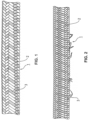
- jeweils eine Seitenansicht eines hochfesten Faserseils mit einer geflochtenen Ummantelung, wobei der an der Ummantelung auftretende Mantelverschleiß in unterschiedlichen Schädigungsgraden dargestellt ist und nach und nach der Seilkern zu Tage tritt,
- Fig. 6 bis Fig. 9:
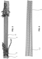
- jeweils eine Draufsicht auf einen Abschnitt eines hochfesten Faserseils mit einer Ummantelung nach einer weiteren Ausführung der Erfindung, wobei hier als Schädigungen der Ummantelung Einschnitte am Seil in verschiedenen Ausprägungsstufen dargestellt sind, und
- Fig. 10 bis Fig. 13:
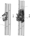
- jeweils einen Abschnitt eines hochfesten Faserseils mit einer Ummantelung nach einer weiteren Ausführung der Erfindung, wobei Schädigungen der Ummantelung in Form einer Quetschung / lokalen Verdickung des Seils in verschiedenen Ausprägungsstufen dargestellt ist.
- Fig. 1 to Fig. 5:
- each a side view of a high-strength fiber rope with a braided sheath, showing the sheath wear occurring on the sheath in different degrees of damage and gradually revealing the core of the rope,
- Figures 6 to 9:
- each a top view of a section of a high-strength fiber rope with a sheath according to a further embodiment of the invention, in which case cuts on the rope are shown in various degrees of severity as damage to the sheath, and
- Figures 10 to 13:
- each a section of a high-strength fiber rope with a sheath according to a further embodiment of the invention, with damage to the sheath in the form of a bruise/local thickening of the rope being shown in various stages of development.
Wie beispielsweise die
Die Ummantelung 2 umgibt den genannten Seilkern 11 und kann unmittelbar auf dem genannten Seilkern sitzen oder ggfs. durch eine Zwischenschicht hiervon beabstandet sein. Die genannte Ummantelung 2 kann insbesondere den Außenmantel des Seils 1 bilden. Der Seilkern 11 kann die gesamte angegebene Zugfestigkeit des Seils 1 übernehmen. Die Ummantelung 2 wirkt nur darüber hinaus unterstützend, insbesondere als Schutz für den Seilkern 11 und als Verschleißindikator.The
Die genannte Ummantelung 2 kann hierbei aus einer einzigen Mantelschicht bestehen oder auch mehrere Mantelschichten umfassen, die übereinanderliegend angeordnet sind.
Wie die Figuren zeigen, umfasst die genannte Ummantelung 2 Litzen 3, die miteinander zu der Ummantelung 2 geflochten sind und jeweils aus hochfesten Synthetikfasern bestehen können oder solche hochfesten Synthetikfasern zumindest aufweisen können.As the figures show, said
Insbesondere können die genannten Litzen 3 der Ummantelung 2 in der eingangs ausführlich beschriebenen Weise aus unterschiedlichen Kunstfasern verschiedener Abrieb- und Zugfestigkeiten und weiter gegebenenfalls unterschiedlicher Werkstoffe gebildet sein. Wie die Figuren zeigen, sind die genannten Litzen 3 vorteilhafterweise in verschiedenen Farben eingefärbt.In particular, the said
In den
- Fig.1
zeigt das Seil 1mit Ummantelung 2 und dieLitzen 3 der Ummantelung in unterschiedlichen Farben. Grad der gezeigten Schädigung ca. 5% der Ablegereife.- Fig.2
zeigt das Seil 1mit Ummantelung 2 jedoch mit sichtbarem Verschleiß der einzelnenLitzen 3 des Mantels. Grad der gezeigten Schädigung ca. 25% der Ablegereife.- Fig.3
zeigt das Seil 1, dessen Ummantelung über einen Teilabschnitt von ca. 90° verschlissen ist und die Litzen 4 des tragenden Seilkernes sichtbar werden. Grad der gezeigten Schädigung ca. 50% der Ablegereife.- Fig.4
zeigt das Seil 1, dessen Ummantelung einen fortgeschrittenen Verschleißzustand in einem Teilabschnitt von ca. 180° aufweist und die Litzen 4 des tragenden Seilkernes in diesem Teilabschnitt gut sichtbar sind. Grad der gezeigten Schädigung ca. 75% der Ablegereife.- Fig.5
zeigt das Seil 1, dessen Ummantelung einen stark fortgeschrittenen Verschleißzustand über den gesamten Seilumfang (360°) aufweist. Der Mantel ist verschlissen und verschoben und die Litzen 4 des tragenden Seiles sind in diesem Teilabschnitt voll sichtbar. Grad der gezeigten Schädigung 100% der Ablegereife.Die Figuren 6 bis 9- zeigen eine Schädigung des Seils in Form von Einschnitten, die zu einem sich graduell ausbreitenden Schädigungsgrad führen.
- Fig.6
zeigt das Seil 1mit Ummantelung 2 und dieLitzen 3 der Ummantelung in unterschiedlichen Farben. Grad der gezeigten Schädigung 0% der Ablegereife.- Fig.7
zeigt das Seil 1, dessen Ummantelung einen sichtbar leichten Einschnitt 5 aufweist. Grad der gezeigten Schädigung ca. 25% der Ablegereife.- Fig.8
zeigt das Seil 1, dessen Ummantelung und eine Litze des tragenden Seiles einen sichtbaren Einschnitt 6 aufweisen. Grad der gezeigten Schädigung ca. 50% der Ablegereife.- Fig.9
zeigt das Seil 1, dessen Ummantelung und mindestens eine Litze des tragenden Seiles einen sichtbaren Durchschnitt 7 aufweisen. Grad der gezeigten Schädigung 100% der Ablegereife.
Die Figuren 10 bis 13- zeigen schließlich eine Schädigung des hochfesten Faserseils in Form von Quetschungen des Seiles.
- Fig.10
zeigt das Seil 1mit Ummantelung 2 und dieLitzen 3 der Ummantelung in unterschiedlichen Farben. Grad der gezeigten Schädigung 0% der Ablegereife.- Fig.11
zeigt das Seil 1 mit einer leichten Quetschung 8 und Ovalisierung des Seilquerschnittes. Grad der gezeigten Schädigung ca. 25% der Ablegereife.- Fig.12
zeigt das Seil 1 mit einer starken Quetschung 9 und einer starken Ovalisierung des Seilquerschnittes. Grad der gezeigten Schädigung ca. 50% der Ablegereife.- Fig.13
zeigt das Seil 1 mit einer sostarken Quetschung 10, dass der Mantel offen ist und die beschädigten Litzen des tragenden Seilkernes austreten. Grad der gezeigten Schädigung 100% der Ablegereife.
- Fig.1
- shows the
rope 1 with thesheath 2 and thestrands 3 of the sheath in different colors. Degree of damage shown approx. 5% of discard age. - Fig.2
- shows the
rope 1 with thesheath 2 but with visible wear of theindividual strands 3 of the sheath. Degree of damage shown approx. 25% of discard age. - Fig.3
- shows the
rope 1, the sheathing of which is worn over a section of about 90° and the strands 4 of the supporting rope core are visible. Degree of damage shown approx. 50% of discard age. - Fig.4
- shows the
rope 1, the sheathing of which has an advanced state of wear in a section of about 180° and the strands 4 of the supporting rope core are clearly visible in this section. Degree of damage shown approx. 75% of discard age. - Fig.5
- shows the
rope 1, the sheathing of which has a very advanced state of wear over the entire circumference of the rope (360°). The sheath is worn and displaced and the strands 4 of the supporting rope are fully visible in this section. Degree of damage shown 100% of discard age. - Figures 6 to 9
- show damage to the rope in the form of cuts, which lead to a gradually spreading degree of damage.
- Fig.6
- shows the
rope 1 with thesheath 2 and thestrands 3 of the sheath in different colors. Degree of damage shown 0% of discard age. - Fig.7
- shows the
rope 1, the sheathing of which has a visible, slight incision 5. Degree of damage shown approx. 25% of discard age. - Fig.8
- shows the
rope 1, the sheath and a strand of the supporting rope have avisible incision 6. Degree of damage shown approx. 50% of discard age. - Fig.9
- shows the
rope 1, whose sheath and at least one strand of the supporting rope have a visible section 7. Degree of damage shown 100% of discard age.
- Figures 10 to 13
- finally show damage to the high-strength fiber rope in the form of crushing of the rope.
- Fig.10
- shows the
rope 1 with thesheath 2 and thestrands 3 of the sheath in different colors. Degree of damage shown 0% of discard age. - Fig.11
- shows the
rope 1 with a slight bruise 8 and ovalization of the rope cross-section. Degree of damage shown approx. 25% of discard age. - Fig.12
- shows the
cable 1 with a strong pinch 9 and a strong ovalization of the cable cross section. Degree of damage shown approx. 50% of discard age. - Fig.13
- shows the
rope 1 with such astrong bruise 10 that the sheath is open and the damaged strands of the supporting rope core emerge. Degree of damage shown 100% of discard age.
Claims (11)
- A high-strength fibre rope for hoisting equipment like cranes having a rope core (11) comprising high-strength synthetic fibres or strands (4) as well as a sheathing (2) surrounding the rope core (11) and indicating wear, characterized in that the sheathing (2) has at least one sheath layer, in which synthetic fibres having different wear resistance and/or tensile strength and/or bending fatigue are interwoven with each other, wherein an extent of damage of the sheath layer can be optically inspected by virtue of the synthetic fibres having different wear resistance and/or tensile strength and/or bending fatigue.
- A high-strength fibre rope according to the preceding claim 1, wherein the synthetic fibres in said at least one sheath layer are composed of various materials and comprise preferably HMPE fibres and polyester fibres.
- A high-strength fibre rope according to claim 1 or 2, characterized in that the sheath layer containing fibres having various wear properties is in the outermost area of the sheathing, especially preferably in the outermost layer of the rope.
- A high-strength fibre rope according to any of the preceding claims, wherein the sheathing (2) has several sheath layers, which differ from each other in regard to the fibre structure thereof and the wear resistance and/or tensile strength and/or bending fatigue of the synthetic fibres used in the sheath layers.
- A high-strength fibre rope according to claim 4, wherein there are provided synthetic fibres in a sheath layer, which differ from any other synthetic fibres of at least one further sheath layer in regard to the wear resistance and/or tensile strength thereof and/or bending fatigue and/or the material thereof.
- A high-strength fibre rope according to any of the preceding claims, wherein the sheathing (2) has sheath layers of different layer thicknesses and/or synthetic fibres and/or strands with different thicknesses from layer to layer.
- A high-strength fibre rope according to any of the preceding claims, wherein the synthetic fibres, which exhibit different wear resistance and tensile strength and are optionally composed of different materials are dyed in different colours.
- A high-strength fibre rope according to any of the preceding claims, wherein the rope core (11) has a colour deviating from that of the sheathing (2).
- A high-strength fibre rope according to any of the preceding claims, wherein the sheathing (2) of the rope core (11) forms the outer sheath of the rope (1).
- Hoisting equipment, in particular cranes such as a tower slewing crane, a telescopic crane, a dockside crane or a ship crane, comprising a high-strength fibre rope (1) configured according to any of the preceding claims.
- Hoisting equipment according to claim 10, wherein the high-strength fibre rope (1) forms the crane hoist rope or a crane boom suspension rope.
Applications Claiming Priority (2)
| Application Number | Priority Date | Filing Date | Title |
|---|---|---|---|
| DE102015013604 | 2015-10-21 | ||
| PCT/EP2016/075251 WO2017068054A1 (en) | 2015-10-21 | 2016-10-20 | High-strength fiber rope for lifting devices such as cranes |
Publications (2)
| Publication Number | Publication Date |
|---|---|
| EP3365492A1 EP3365492A1 (en) | 2018-08-29 |
| EP3365492B1 true EP3365492B1 (en) | 2023-07-05 |
Family
ID=57144945
Family Applications (2)
| Application Number | Title | Priority Date | Filing Date |
|---|---|---|---|
| EP16782187.5A Active EP3180472B1 (en) | 2015-10-21 | 2016-10-17 | Device for detecting the replacement state of wear of a high-strength fibre cable for hoisting devices |
| EP16784209.5A Active EP3365492B1 (en) | 2015-10-21 | 2016-10-20 | High-strength fiber rope for lifting devices such as cranes |
Family Applications Before (1)
| Application Number | Title | Priority Date | Filing Date |
|---|---|---|---|
| EP16782187.5A Active EP3180472B1 (en) | 2015-10-21 | 2016-10-17 | Device for detecting the replacement state of wear of a high-strength fibre cable for hoisting devices |
Country Status (13)
| Country | Link |
|---|---|
| US (2) | US11008702B2 (en) |
| EP (2) | EP3180472B1 (en) |
| JP (1) | JP6916173B2 (en) |
| KR (1) | KR20180071282A (en) |
| CN (1) | CN108350650B (en) |
| AU (1) | AU2016343543B2 (en) |
| BR (1) | BR112018007015B1 (en) |
| ES (2) | ES2673902T3 (en) |
| HU (1) | HUE037052T2 (en) |
| PL (1) | PL3180472T3 (en) |
| PT (1) | PT3365492T (en) |
| TR (1) | TR201808691T4 (en) |
| WO (2) | WO2017067651A1 (en) |
Families Citing this family (18)
| Publication number | Priority date | Publication date | Assignee | Title |
|---|---|---|---|---|
| HUE037052T2 (en) | 2015-10-21 | 2018-08-28 | Liebherr Components Biberach | Device for detecting the replacement state of wear of a high-strength fibre cable for hoisting devices |
| ES2896099T3 (en) * | 2015-12-16 | 2022-02-23 | Teufelberger Fiber Rope Gmbh | Method for determining the wear replacement status of a rope made of a textile fiber material |
| US10544012B2 (en) | 2016-01-29 | 2020-01-28 | Manitowoc Crane Companies, Llc | Visual outrigger monitoring system |
| US10829347B2 (en) | 2016-11-22 | 2020-11-10 | Manitowoc Crane Companies, Llc | Optical detection system for lift crane |
| EP3409629B2 (en) * | 2017-06-01 | 2024-02-28 | Otis Elevator Company | Image analytics for elevator maintenance |
| DE202017107301U1 (en) * | 2017-09-01 | 2018-12-07 | Liebherr-Werk Biberach Gmbh | Tower Crane |
| US10870556B2 (en) * | 2017-12-12 | 2020-12-22 | Otis Elevator Company | Method and system for detecting elevator car operating panel condition |
| US10961082B2 (en) * | 2018-01-02 | 2021-03-30 | Otis Elevator Company | Elevator inspection using automated sequencing of camera presets |
| US10941018B2 (en) * | 2018-01-04 | 2021-03-09 | Otis Elevator Company | Elevator auto-positioning for validating maintenance |
| WO2019201596A1 (en) | 2018-04-18 | 2019-10-24 | Bridon International Limited | Monitoring condition of a rope |
| DE102018123758A1 (en) | 2018-06-28 | 2020-01-02 | Liebherr-Components Biberach Gmbh | Method and device for setting the maturity detection of high-strength fiber ropes |
| CN109179169A (en) * | 2018-09-29 | 2019-01-11 | 杭州西奥电梯有限公司 | A kind of hoisting rope for elevator and its sentence useless method |
| US11906445B2 (en) * | 2018-10-10 | 2024-02-20 | Goodrich Corporation | Automated defect detection for wire rope using image processing techniques |
| US20200122974A1 (en) * | 2018-10-18 | 2020-04-23 | Otis Elevator Company | In-situ system for health monitoring of elevator system |
| US20200122975A1 (en) * | 2018-10-19 | 2020-04-23 | Otis Elevator Company | Elevator system tension member surface anomoly detection |
| JP7188016B2 (en) * | 2018-11-27 | 2022-12-13 | 株式会社タダノ | crane equipment |
| CN111021113B (en) * | 2019-12-25 | 2023-06-02 | 青岛鲁普耐特绳网研究院有限公司 | Aramid fiber dyed rope |
| CN112225039B (en) * | 2020-12-10 | 2021-03-16 | 湖南久钰电子有限公司 | Pulley on-line monitoring method and system, electronic equipment and storage medium |
Citations (1)
| Publication number | Priority date | Publication date | Assignee | Title |
|---|---|---|---|---|
| EP2434050B1 (en) * | 2010-09-23 | 2015-09-09 | Geo. Gleistein&Sohn GmbH | Rope comprising a sensor |
Family Cites Families (55)
| Publication number | Priority date | Publication date | Assignee | Title |
|---|---|---|---|---|
| US3805667A (en) * | 1970-08-21 | 1974-04-23 | Columbian Rope Co | Braided rope |
| DE2222312A1 (en) | 1972-05-06 | 1973-11-22 | Battelle Institut E V | High strength plastics cable - eg for towing |
| FR2224171B1 (en) * | 1973-04-09 | 1976-11-12 | Rhone Poulenc Ind | |
| DE2455273C3 (en) | 1974-11-22 | 1978-01-19 | Feiten & Guilleaume Carlswerk AG, 5000 Köln | Plastic crane rope |
| JPS62274246A (en) * | 1986-05-23 | 1987-11-28 | Toshiba Corp | Optical flaw detecting device |
| DE3641816A1 (en) * | 1986-12-06 | 1988-06-16 | Robert Prof Dr Ing Massen | METHOD AND ARRANGEMENT FOR MEASURING AND / OR MONITORING PROPERTIES OF YARNS AND ROPES |
| CA2169431C (en) | 1995-03-06 | 2005-07-12 | Claudio De Angelis | Equipment for recognising when synthetic fibre cables are ripe for being discarded |
| US6123176A (en) * | 1996-05-28 | 2000-09-26 | Otis Elevator Company | Rope tension monitoring assembly and method |
| EP0935805B1 (en) * | 1996-11-04 | 2003-07-16 | Eric White | Electrobraid fence |
| US5992574A (en) * | 1996-12-20 | 1999-11-30 | Otis Elevator Company | Method and apparatus to inspect hoisting ropes |
| JPH10318741A (en) | 1997-05-16 | 1998-12-04 | Kobe Steel Ltd | Method and apparatus for measurement of elongation of wire rope |
| IL133050A (en) | 1998-12-07 | 2003-12-10 | Inventio Ag | Device for identification of need to replace synthetic fiber ropes |
| SG78407A1 (en) | 1999-01-22 | 2001-02-20 | Inventio Ag | Sheathed synthetic fiber rope |
| JP2001192183A (en) | 2000-01-07 | 2001-07-17 | Hitachi Ltd | Deterioration state discriminating method for synthetic fiber rope and elevator |
| US6479797B1 (en) | 2000-06-05 | 2002-11-12 | Tigers Polymer Corporation | Snow melting apparatus and heating wire for melting snow |
| US7029490B2 (en) * | 2001-09-13 | 2006-04-18 | Arthrex, Inc. | High strength suture with coating and colored trace |
| US20030062226A1 (en) | 2001-10-03 | 2003-04-03 | Stucky Paul A. | Elevator load bearing assembly having a ferromagnetic element that provides an indication of local strain |
| US20030062225A1 (en) | 2001-10-03 | 2003-04-03 | Stucky Paul A. | Elevator load bearing assembly having a detectable element that is indicative of local strain |
| US7117981B2 (en) | 2001-12-19 | 2006-10-10 | Otis Elevator Company | Load bearing member for use in an elevator system having external markings for indicating a condition of the assembly |
| US6999641B2 (en) | 2002-05-03 | 2006-02-14 | Jerry Gene Williams | Measurement of large strains in ropes using plastic optical fibers |
| JP2006500303A (en) | 2002-09-25 | 2006-01-05 | オーチス エレベータ カンパニー | Elevator belt assembly with pre-stretched composite cord |
| EP1586526B1 (en) * | 2003-01-24 | 2015-09-30 | Mitsubishi Denki Kabushiki Kaisha | Elevator rope |
| EP1530040B1 (en) | 2003-11-04 | 2012-09-12 | Inventio AG | Method and device for checking carrying means |
| US7134267B1 (en) * | 2003-12-16 | 2006-11-14 | Samson Rope Technologies | Wrapped yarns for use in ropes having predetermined surface characteristics |
| US7329271B2 (en) * | 2003-12-18 | 2008-02-12 | Ethicon, Inc. | High strength suture with absorbable core |
| US7357810B2 (en) * | 2003-12-18 | 2008-04-15 | Ethicon, Inc. | High strength suture with absorbable core and suture anchor combination |
| US7285034B2 (en) * | 2003-12-30 | 2007-10-23 | Mattel, Inc. | Toy play set |
| AT503634A1 (en) | 2006-03-31 | 2007-11-15 | Teufelberger Gmbh | ROPE |
| EP1905892B1 (en) | 2006-09-29 | 2011-11-16 | Inventio AG | Synthetic fibre rope, lift installation with such a synthetic fibre rope and method for making a synthetic fibre rope |
| SG143143A1 (en) | 2006-12-04 | 2008-06-27 | Inventio Ag | Synthetic fiber rope |
| EP1930496B1 (en) | 2006-12-04 | 2013-07-24 | Inventio AG | Synthetic fibre rope |
| US7703372B1 (en) * | 2007-08-14 | 2010-04-27 | New England Ropes Corp. | Climbing rope |
| CA2988667C (en) * | 2009-04-27 | 2020-09-22 | Teleflex Medical Incorporated | Colored suture construction |
| EP2427758B1 (en) * | 2009-05-05 | 2019-07-31 | Actuant Corporation | Non-contact acoustic signal propagation property evaluation of synthetic fiber rope |
| DE202009014031U1 (en) * | 2009-10-16 | 2009-12-24 | Manitowoc Crane Group France Sas | Synthetic rope as a carrier for cranes and other hoists |
| BR112012016880B1 (en) * | 2010-01-07 | 2020-03-17 | Dsm Ip Assets B.V. | HYBRID CABLE AND PROCESS TO END A HYBRID CABLE |
| ES2549588T3 (en) * | 2010-06-08 | 2015-10-29 | Dsm Ip Assets B.V. | Hybrid rope |
| US9063008B2 (en) * | 2010-07-23 | 2015-06-23 | Inventio Ag | Nondestructive testing of a carrier element of an elevator installation |
| DE202011001846U1 (en) * | 2011-01-24 | 2012-04-30 | Liebherr-Components Biberach Gmbh | Device for detecting the Ablegereife a high-strength fiber rope when used on hoists |
| WO2012162556A1 (en) * | 2011-05-24 | 2012-11-29 | Samson Rope Technologies | Rope structures and methods |
| US9080263B2 (en) * | 2012-02-10 | 2015-07-14 | Novus Scientific Ab | Multifilaments with time-dependent characteristics, and medical products made from such multifilaments |
| JP5769875B2 (en) * | 2012-03-28 | 2015-08-26 | 三菱電機株式会社 | Wire rope inspection device |
| US20140157973A1 (en) * | 2012-07-12 | 2014-06-12 | Thomas Plante | Braided rope |
| CN104603605A (en) * | 2012-09-04 | 2015-05-06 | 帝人芳纶有限公司 | Method for non-destructive testing of synthetic ropes and rope suitable for use therein |
| DE202013101326U1 (en) | 2013-03-27 | 2013-06-04 | Pfeifer Drako Drahtseilwerk Gmbh & Co. Kg | Multistrand steel wire rope with a multi-core fiber core |
| CN103257465B (en) * | 2013-04-17 | 2015-11-11 | 合肥京东方光电科技有限公司 | A kind of pick-up unit and detection method |
| CN103706086B (en) * | 2013-12-24 | 2016-02-10 | 特大纺织制品(深圳)有限公司 | Seamless rock-climbing quick draw, weaving loom and textile technology thereof |
| EP3119716B1 (en) | 2014-03-21 | 2018-10-10 | Liebherr-Components Biberach GmbH | Device for determining the replacement state of wear of a rope during use in lifting gear |
| CN103993548A (en) * | 2014-05-07 | 2014-08-20 | 长安大学 | Multi-camera stereoscopic shooting based pavement damage crack detection system and method |
| CN104063716A (en) * | 2014-07-01 | 2014-09-24 | 重庆迈高电梯有限公司 | Method for detecting breaking strand or wire of wire rope |
| AT516444B1 (en) * | 2014-11-05 | 2016-09-15 | Teufelberger Fiber Rope Gmbh | Rope made of textile fiber material |
| HUE037052T2 (en) | 2015-10-21 | 2018-08-28 | Liebherr Components Biberach | Device for detecting the replacement state of wear of a high-strength fibre cable for hoisting devices |
| DE202016002171U1 (en) * | 2016-04-05 | 2017-07-07 | Liebherr-Werk Biberach Gmbh | Device for monitoring operating data and / or determining the Ablegereife a rope when used on lifting equipment |
| WO2017223555A1 (en) * | 2016-06-24 | 2017-12-28 | Actuant Corporation | Apparatus and method for measuring properties of a rope |
| KR102092145B1 (en) * | 2017-04-20 | 2020-03-24 | 퇴펠베르게르 피베르 로페 게엠베하 | High-strength fibre rope for hoisting equipment such as cranes |
-
2016
- 2016-10-17 HU HUE16782187A patent/HUE037052T2/en unknown
- 2016-10-17 TR TR2018/08691T patent/TR201808691T4/en unknown
- 2016-10-17 PL PL16782187T patent/PL3180472T3/en unknown
- 2016-10-17 EP EP16782187.5A patent/EP3180472B1/en active Active
- 2016-10-17 BR BR112018007015-7A patent/BR112018007015B1/en active IP Right Grant
- 2016-10-17 AU AU2016343543A patent/AU2016343543B2/en active Active
- 2016-10-17 ES ES16782187.5T patent/ES2673902T3/en active Active
- 2016-10-17 WO PCT/EP2016/001716 patent/WO2017067651A1/en active Application Filing
- 2016-10-17 JP JP2018517627A patent/JP6916173B2/en active Active
- 2016-10-17 CN CN201680061043.8A patent/CN108350650B/en active Active
- 2016-10-20 ES ES16784209T patent/ES2958400T3/en active Active
- 2016-10-20 KR KR1020187012642A patent/KR20180071282A/en unknown
- 2016-10-20 PT PT167842095T patent/PT3365492T/en unknown
- 2016-10-20 WO PCT/EP2016/075251 patent/WO2017068054A1/en active Application Filing
- 2016-10-20 US US15/769,474 patent/US11008702B2/en active Active
- 2016-10-20 EP EP16784209.5A patent/EP3365492B1/en active Active
-
2018
- 2018-04-19 US US15/957,459 patent/US10822742B2/en active Active
Patent Citations (1)
| Publication number | Priority date | Publication date | Assignee | Title |
|---|---|---|---|---|
| EP2434050B1 (en) * | 2010-09-23 | 2015-09-09 | Geo. Gleistein&Sohn GmbH | Rope comprising a sensor |
Also Published As
| Publication number | Publication date |
|---|---|
| EP3180472B1 (en) | 2018-03-21 |
| ES2958400T3 (en) | 2024-02-08 |
| US20180305864A1 (en) | 2018-10-25 |
| JP6916173B2 (en) | 2021-08-11 |
| KR20180071282A (en) | 2018-06-27 |
| AU2016343543A1 (en) | 2018-04-19 |
| TR201808691T4 (en) | 2018-07-23 |
| CN108350650A (en) | 2018-07-31 |
| PL3180472T3 (en) | 2018-10-31 |
| US10822742B2 (en) | 2020-11-03 |
| US11008702B2 (en) | 2021-05-18 |
| EP3180472A1 (en) | 2017-06-21 |
| PT3365492T (en) | 2023-09-11 |
| ES2673902T3 (en) | 2018-06-26 |
| AU2016343543B2 (en) | 2021-04-01 |
| US20180238815A1 (en) | 2018-08-23 |
| CN108350650B (en) | 2021-06-22 |
| BR112018007015A2 (en) | 2018-10-16 |
| WO2017067651A1 (en) | 2017-04-27 |
| HUE037052T2 (en) | 2018-08-28 |
| EP3365492A1 (en) | 2018-08-29 |
| BR112018007015B1 (en) | 2022-07-12 |
| JP2018532898A (en) | 2018-11-08 |
| WO2017068054A1 (en) | 2017-04-27 |
Similar Documents
| Publication | Publication Date | Title |
|---|---|---|
| EP3365492B1 (en) | High-strength fiber rope for lifting devices such as cranes | |
| EP3215671B1 (en) | Rope made of textile fibre material | |
| EP3392404A1 (en) | High strength fibre cable for hoisting equipment such as cranes | |
| EP1010803B1 (en) | Device for detecting the end of service life for synthetic fibre ropes | |
| EP0731209B1 (en) | Device for detecting the end of service life for synthetic fibre ropes | |
| EP2002051B1 (en) | Rope | |
| EP3793928B1 (en) | Device for setting the discarding criteria detection of high-strength fiber ropes, and hoisting gear having such a device | |
| DE102015017157A1 (en) | High strength fiber rope for hoists such as cranes | |
| EP3443158B1 (en) | Hoisting rope | |
| DE10297299T5 (en) | Elevator rope with a detectable element that is indicative of local stress | |
| EP1815061B1 (en) | Strand with increased adherence to metal disks | |
| EP3099854B1 (en) | Rope assembly | |
| DE102009056550B4 (en) | Suspension for lifting equipment | |
| EP3391018B1 (en) | Method for determining the point of discard of a rope made of textile fibrous material | |
| DE212012000169U1 (en) | Elevator rope in the form of a steel cable with a core of high-strength plastic fibers |
Legal Events
| Date | Code | Title | Description |
|---|---|---|---|
| STAA | Information on the status of an ep patent application or granted ep patent |
Free format text: STATUS: THE INTERNATIONAL PUBLICATION HAS BEEN MADE |
|
| PUAI | Public reference made under article 153(3) epc to a published international application that has entered the european phase |
Free format text: ORIGINAL CODE: 0009012 |
|
| STAA | Information on the status of an ep patent application or granted ep patent |
Free format text: STATUS: REQUEST FOR EXAMINATION WAS MADE |
|
| 17P | Request for examination filed |
Effective date: 20180420 |
|
| AK | Designated contracting states |
Kind code of ref document: A1 Designated state(s): AL AT BE BG CH CY CZ DE DK EE ES FI FR GB GR HR HU IE IS IT LI LT LU LV MC MK MT NL NO PL PT RO RS SE SI SK SM TR |
|
| AX | Request for extension of the european patent |
Extension state: BA ME |
|
| DAV | Request for validation of the european patent (deleted) | ||
| DAX | Request for extension of the european patent (deleted) | ||
| REG | Reference to a national code |
Ref country code: DE Ref legal event code: R079 Ref document number: 502016015926 Country of ref document: DE Free format text: PREVIOUS MAIN CLASS: D07B0001140000 Ipc: B66C0015000000 Ref legal event code: R079 Free format text: PREVIOUS MAIN CLASS: D07B0001140000 Ipc: B66C0015000000 |
|
| RIC1 | Information provided on ipc code assigned before grant |
Ipc: G01N 21/952 20060101ALI20230222BHEP Ipc: D07B 1/00 20060101ALI20230222BHEP Ipc: D07B 1/02 20060101ALI20230222BHEP Ipc: D07B 1/14 20060101ALI20230222BHEP Ipc: B66B 7/12 20060101ALI20230222BHEP Ipc: B66D 1/54 20060101ALI20230222BHEP Ipc: B66C 15/00 20060101AFI20230222BHEP |
|
| GRAP | Despatch of communication of intention to grant a patent |
Free format text: ORIGINAL CODE: EPIDOSNIGR1 |
|
| STAA | Information on the status of an ep patent application or granted ep patent |
Free format text: STATUS: GRANT OF PATENT IS INTENDED |
|
| INTG | Intention to grant announced |
Effective date: 20230405 |
|
| GRAS | Grant fee paid |
Free format text: ORIGINAL CODE: EPIDOSNIGR3 |
|
| GRAA | (expected) grant |
Free format text: ORIGINAL CODE: 0009210 |
|
| STAA | Information on the status of an ep patent application or granted ep patent |
Free format text: STATUS: THE PATENT HAS BEEN GRANTED |
|
| P01 | Opt-out of the competence of the unified patent court (upc) registered |
Effective date: 20230519 |
|
| AK | Designated contracting states |
Kind code of ref document: B1 Designated state(s): AL AT BE BG CH CY CZ DE DK EE ES FI FR GB GR HR HU IE IS IT LI LT LU LV MC MK MT NL NO PL PT RO RS SE SI SK SM TR |
|
| REG | Reference to a national code |
Ref country code: CH Ref legal event code: EP |
|
| REG | Reference to a national code |
Ref country code: AT Ref legal event code: REF Ref document number: 1584697 Country of ref document: AT Kind code of ref document: T Effective date: 20230715 |
|
| REG | Reference to a national code |
Ref country code: DE Ref legal event code: R096 Ref document number: 502016015926 Country of ref document: DE |
|
| REG | Reference to a national code |
Ref country code: IE Ref legal event code: FG4D Free format text: LANGUAGE OF EP DOCUMENT: GERMAN |
|
| REG | Reference to a national code |
Ref country code: PT Ref legal event code: SC4A Ref document number: 3365492 Country of ref document: PT Date of ref document: 20230911 Kind code of ref document: T Free format text: AVAILABILITY OF NATIONAL TRANSLATION Effective date: 20230905 |
|
| REG | Reference to a national code |
Ref country code: NL Ref legal event code: FP |
|
| REG | Reference to a national code |
Ref country code: LT Ref legal event code: MG9D |
|
| PGFP | Annual fee paid to national office [announced via postgrant information from national office to epo] |
Ref country code: NL Payment date: 20231023 Year of fee payment: 8 |
|
| PG25 | Lapsed in a contracting state [announced via postgrant information from national office to epo] |
Ref country code: GR Free format text: LAPSE BECAUSE OF FAILURE TO SUBMIT A TRANSLATION OF THE DESCRIPTION OR TO PAY THE FEE WITHIN THE PRESCRIBED TIME-LIMIT Effective date: 20231006 |
|
| PGFP | Annual fee paid to national office [announced via postgrant information from national office to epo] |
Ref country code: GB Payment date: 20231025 Year of fee payment: 8 |
|
| PGFP | Annual fee paid to national office [announced via postgrant information from national office to epo] |
Ref country code: ES Payment date: 20231117 Year of fee payment: 8 |
|
| PGFP | Annual fee paid to national office [announced via postgrant information from national office to epo] |
Ref country code: IS Payment date: 20231031 Year of fee payment: 8 |
|
| PG25 | Lapsed in a contracting state [announced via postgrant information from national office to epo] |
Ref country code: SE Free format text: LAPSE BECAUSE OF FAILURE TO SUBMIT A TRANSLATION OF THE DESCRIPTION OR TO PAY THE FEE WITHIN THE PRESCRIBED TIME-LIMIT Effective date: 20230705 Ref country code: RS Free format text: LAPSE BECAUSE OF FAILURE TO SUBMIT A TRANSLATION OF THE DESCRIPTION OR TO PAY THE FEE WITHIN THE PRESCRIBED TIME-LIMIT Effective date: 20230705 Ref country code: NO Free format text: LAPSE BECAUSE OF FAILURE TO SUBMIT A TRANSLATION OF THE DESCRIPTION OR TO PAY THE FEE WITHIN THE PRESCRIBED TIME-LIMIT Effective date: 20231005 Ref country code: LV Free format text: LAPSE BECAUSE OF FAILURE TO SUBMIT A TRANSLATION OF THE DESCRIPTION OR TO PAY THE FEE WITHIN THE PRESCRIBED TIME-LIMIT Effective date: 20230705 Ref country code: LT Free format text: LAPSE BECAUSE OF FAILURE TO SUBMIT A TRANSLATION OF THE DESCRIPTION OR TO PAY THE FEE WITHIN THE PRESCRIBED TIME-LIMIT Effective date: 20230705 Ref country code: HR Free format text: LAPSE BECAUSE OF FAILURE TO SUBMIT A TRANSLATION OF THE DESCRIPTION OR TO PAY THE FEE WITHIN THE PRESCRIBED TIME-LIMIT Effective date: 20230705 Ref country code: GR Free format text: LAPSE BECAUSE OF FAILURE TO SUBMIT A TRANSLATION OF THE DESCRIPTION OR TO PAY THE FEE WITHIN THE PRESCRIBED TIME-LIMIT Effective date: 20231006 Ref country code: FI Free format text: LAPSE BECAUSE OF FAILURE TO SUBMIT A TRANSLATION OF THE DESCRIPTION OR TO PAY THE FEE WITHIN THE PRESCRIBED TIME-LIMIT Effective date: 20230705 |
|
| PGFP | Annual fee paid to national office [announced via postgrant information from national office to epo] |
Ref country code: PT Payment date: 20231016 Year of fee payment: 8 Ref country code: IT Payment date: 20231027 Year of fee payment: 8 Ref country code: FR Payment date: 20231023 Year of fee payment: 8 Ref country code: DE Payment date: 20231018 Year of fee payment: 8 Ref country code: CZ Payment date: 20231009 Year of fee payment: 8 |
|
| REG | Reference to a national code |
Ref country code: ES Ref legal event code: FG2A Ref document number: 2958400 Country of ref document: ES Kind code of ref document: T3 Effective date: 20240208 |
|
| PG25 | Lapsed in a contracting state [announced via postgrant information from national office to epo] |
Ref country code: PL Free format text: LAPSE BECAUSE OF FAILURE TO SUBMIT A TRANSLATION OF THE DESCRIPTION OR TO PAY THE FEE WITHIN THE PRESCRIBED TIME-LIMIT Effective date: 20230705 |