EP3409629B2 - Image analytics for elevator maintenance - Google Patents
Image analytics for elevator maintenance Download PDFInfo
- Publication number
- EP3409629B2 EP3409629B2 EP17305643.3A EP17305643A EP3409629B2 EP 3409629 B2 EP3409629 B2 EP 3409629B2 EP 17305643 A EP17305643 A EP 17305643A EP 3409629 B2 EP3409629 B2 EP 3409629B2
- Authority
- EP
- European Patent Office
- Prior art keywords
- image
- elevator
- current image
- reference image
- elevator system
- Prior art date
- Legal status (The legal status is an assumption and is not a legal conclusion. Google has not performed a legal analysis and makes no representation as to the accuracy of the status listed.)
- Active
Links
- 238000012423 maintenance Methods 0.000 title claims description 42
- 238000000034 method Methods 0.000 claims description 28
- 238000010191 image analysis Methods 0.000 claims description 25
- 230000004044 response Effects 0.000 claims description 19
- 238000009434 installation Methods 0.000 claims description 5
- 238000012360 testing method Methods 0.000 claims description 5
- 238000004891 communication Methods 0.000 claims description 4
- 230000000977 initiatory effect Effects 0.000 claims 1
- 230000008569 process Effects 0.000 description 5
- 230000008859 change Effects 0.000 description 4
- 229910000831 Steel Inorganic materials 0.000 description 2
- 230000001133 acceleration Effects 0.000 description 2
- 239000000428 dust Substances 0.000 description 2
- 230000000694 effects Effects 0.000 description 2
- 238000003384 imaging method Methods 0.000 description 2
- 230000007246 mechanism Effects 0.000 description 2
- 239000010959 steel Substances 0.000 description 2
- 230000032683 aging Effects 0.000 description 1
- 230000004075 alteration Effects 0.000 description 1
- 238000004590 computer program Methods 0.000 description 1
- 238000012790 confirmation Methods 0.000 description 1
- 230000001419 dependent effect Effects 0.000 description 1
- 238000007689 inspection Methods 0.000 description 1
- 238000012986 modification Methods 0.000 description 1
- 230000004048 modification Effects 0.000 description 1
- 238000012544 monitoring process Methods 0.000 description 1
- 238000012552 review Methods 0.000 description 1
- 230000003442 weekly effect Effects 0.000 description 1
Images

Classifications
-
- B—PERFORMING OPERATIONS; TRANSPORTING
- B66—HOISTING; LIFTING; HAULING
- B66B—ELEVATORS; ESCALATORS OR MOVING WALKWAYS
- B66B5/00—Applications of checking, fault-correcting, or safety devices in elevators
- B66B5/0006—Monitoring devices or performance analysers
- B66B5/0018—Devices monitoring the operating condition of the elevator system
- B66B5/0025—Devices monitoring the operating condition of the elevator system for maintenance or repair
-
- B—PERFORMING OPERATIONS; TRANSPORTING
- B66—HOISTING; LIFTING; HAULING
- B66B—ELEVATORS; ESCALATORS OR MOVING WALKWAYS
- B66B5/00—Applications of checking, fault-correcting, or safety devices in elevators
- B66B5/0087—Devices facilitating maintenance, repair or inspection tasks
-
- G—PHYSICS
- G06—COMPUTING; CALCULATING OR COUNTING
- G06T—IMAGE DATA PROCESSING OR GENERATION, IN GENERAL
- G06T7/00—Image analysis
- G06T7/0002—Inspection of images, e.g. flaw detection
- G06T7/0004—Industrial image inspection
- G06T7/001—Industrial image inspection using an image reference approach
-
- H—ELECTRICITY
- H04—ELECTRIC COMMUNICATION TECHNIQUE
- H04N—PICTORIAL COMMUNICATION, e.g. TELEVISION
- H04N23/00—Cameras or camera modules comprising electronic image sensors; Control thereof
Definitions
- the subject matter disclosed herein generally relates to elevator systems and, more particularly, to the use of image analytics to facilitate elevator maintenance.
- Existing elevator systems may include a camera installed at the top or bottom of the elevator car.
- the image from the camera may be accessed by a user (e.g., a mechanic or service person) so that the user can perform an inspection of the elevator hoistway remotely, without needing to physically enter the hoistway.
- a user e.g., a mechanic or service person
- US 2017/0015521 A1 discloses a device for monitoring a movement of at least one door (6, 16), in particular an elevator door (6, 16), comprising: at least one picture recording device (18) configured for recording a plurality of pictures of at least one portion of the at least one door (6, 16) during a movement of the at least one door (6, 16); at least one storing device (17) configured for storing a plurality of reference pictures; a comparison device (19), which is configured for comparing at least one of the recorded pictures with at least one of the reference pictures to determine a difference measure representative of the difference between the at least one stored picture and the at least one reference picture; and for issuing an alarm message when the difference measure exceeds a predetermined limit.
- US 2011/0067958 A1 discloses an elevator system and a method for maintenance of such an elevator system including a device for receiving a plurality of sensor signals.
- the device is mounted on at least one elevator car or at least one counterweight of the elevator system.
- the device includes at least one processor and at least one computer-readable data store in at least one device housing.
- a first sensor for generating a sensor signal is a position sensor and/or a speed sensor and/or an acceleration sensor which is mounted in and/or on the device housing.
- JP 2015-151207 A discloses a pit state confirmation system 20 comprising: an imaging section 22 that images predetermined areas in a pit 10 below a hoistway 12 at maintenance decision time intervals; a discriminating section 24 that divides the images taken by the imaging section 22 into a plurality of squares and discriminates brightness of each square between two values of a white level and a black level; and comparing/outputting section 26 that compares the two values discriminated by the discriminating section 24 with two values previously discriminated for each square, and when the number of squares which change from the white level to the black level or from the black level to the white level surpasses a predetermined threshold, outputs a maintenance signal showing that maintenance is necessary.
- an elevator system according to claim 1 is provided.
- Further embodiments of the elevator systems may include wherein the current image is acquired periodically.
- Further embodiments of the elevator systems may include wherein the current image is acquired in response to an event.
- Further embodiments of the elevator systems may include wherein the comparing the current image to the reference image generates an image comparison value.
- Further embodiments of the elevator systems may include wherein the image analysis system initiates the maintenance notification in response to the image comparison value exceeding a threshold value.
- Further embodiments of the elevator systems may include wherein the threshold value changes over time.
- Further embodiments of the elevator systems may include wherein the image comparison value is generated in response to differences between the current image and the reference image.
- Further embodiments of the elevator systems may include wherein the image comparison value is generated in response to pixel differences between the current image and the reference image.
- Further embodiments of the elevator systems may include wherein the maintenance notification includes the reference image.
- Further embodiments of the elevator systems may include wherein the camera is located at a top of the elevator hoistway, at a bottom of the elevator hoistway, on top of the elevator car, on a bottom of the elevator car or inside that elevator car.
- Further embodiments of the elevator systems may include wherein the reference image is obtained after installation and test of the elevator system and prior to operation of the elevator system in a normal mode of operation.
- Further embodiments of the method may include wherein the current image is acquired periodically.
- Further embodiments of the method may include wherein the current image is acquired in response to an event.
- Further embodiments of the method may include wherein the comparing the current image to the reference image generates an image comparison value.
- Further embodiments of the method may include wherein the maintenance notification is initiated in response to the image comparison value exceeding a threshold value.
- Further embodiments of the method may include wherein the threshold value changes over time.
- Further embodiments of the method may include wherein the image comparison value is generated in response to differences between the current image and the reference image.
- Further embodiments of the method may include wherein the image comparison value is generated in response to pixel differences between the current image and the reference image.
- Further embodiments of the method may include wherein the maintenance notification includes the reference image.
- Further embodiments of the method may include wherein the reference image is obtained after installation and test of the elevator system and prior to operation of the elevator system in a normal mode of operation.
- inventions include the ability to automatically detect the need for maintenance of an elevator system using images from a camera. Current images are repeatedly compared to a reference image to determine the need for maintenance of the elevator system.
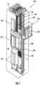
- FIG. 1 is a perspective view of an elevator system 101 including an elevator car 103, a counterweight 105, a roping 107, a guide rail 109, a machine 111, a position encoder 113, and a controller 115.
- the elevator car 103 and counterweight 105 are connected to each other by the roping 107.
- the roping 107 may include or be configured as, for example, ropes, steel cables, and/or coated-steel belts.
- the counterweight 105 is configured to balance a load of the elevator car 103 and is configured to facilitate movement of the elevator car 103 concurrently and in an opposite direction with respect to the counterweight 105 within an elevator hoistway 117 and along the guide rail 109.
- the roping 107 engages the machine 111, which is part of an overhead structure of the elevator system 101.
- the machine 111 is configured to control movement between the elevator car 103 and the counterweight 105.
- the position encoder 113 may be mounted on an upper sheave of a speed-governor system 119 and may be configured to provide position signals related to a position of the elevator car 103 within the elevator hoistway 117. In other embodiments, the position encoder 113 may be directly mounted to a moving component of the machine 111, or may be located in other positions and/or configurations as known in the art.
- the controller 115 is located, as shown, in a controller room 121 of the elevator hoistway 117 and is configured to control the operation of the elevator system 101, and particularly the elevator car 103.
- the controller 115 may provide drive signals to the machine 111 to control the acceleration, deceleration, leveling, stopping, etc. of the elevator car 103.
- the controller 115 may also be configured to receive position signals from the position encoder 113.
- the elevator car 103 may stop at one or more landings 125 as controlled by the controller 115.
- the controller 115 can be located and/or configured in other locations or positions within the elevator system 101.
- the machine 111 may include a motor or similar driving mechanism.
- the machine 111 is configured to include an electrically driven motor.
- the power supply for the motor may be any power source, including a power grid, which, in combination with other components, is supplied to the motor.
- FIG. 1 is merely a non-limiting example presented for illustrative and explanatory purposes.
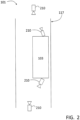
- FIG. 2 depicts the elevator system 101 in an example embodiment.
- one or more cameras 210 are mounted in the elevator system.
- the cameras 210 may be mounted at the top of the hoistway 117, at the bottom of the hoistway 117, on top of elevator car 103, on the bottom of elevator car 103, or any other location in the elevator system, including within the elevator car 103.
- images from the one or more cameras 210 are analyzed to determine if maintenance on the elevator system is needed.
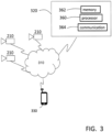
- FIG. 3 depicts a system architecture in an example embodiment.
- the one or more cameras 210 acquire images and transmit the images to a network 310.
- the image from each camera 210 may comprise a single image or a sequence of images (e.g., video).
- the network 310 may include one or more of a wireline network; a wireless network; a local area network (LAN); and a wide area network (WAN), etc.
- Images from the one or more cameras 210 are provided to an image analysis system 320 via network 310.
- the image analysis system 320 may be implemented by the elevator controller 115.
- the image analysis system 320 may also be hosted on a remote computing system, such as a cloud computing platform.
- the image analysis system 320 may include a processor 360, memory 362 and communication module 364 as shown in FIG. 3 .
- the processor 360 can be any type or combination of computer processors, such as a microprocessor, microcontroller, digital signal processor, application specific integrated circuit, programmable logic device, and/or field programmable gate array.
- the memory 362 is an example of a non-transitory computer readable storage medium tangibly embodied in the image analysis system 320 including executable instructions stored therein, for instance, as firmware.
- Processor 360 executes the intrusions in memory 362 to implement the operations described herein.
- the communication module 364 may implement one or more communication protocols to enable receiving images over network 310 and sending notifications over the network to a user device 330.
- the user device 330 may receive a maintenance notification initiated by the image analysis system 320.
- the mobile device 330 may include a device that is carried by a person, such as a smart phone, PDA, tablet, laptop, etc.
- the mobile device 330 may include wearable items, such as a smart watch, eyewear, etc.
- the user device 330 may receive a maintenance notification along with one or more images selected from the camera(s) 210.
- the user device 330 may also be able to access camera(s) 210 to obtain a real time images from the camera(s) 210.
- the user device 330 may also control characteristics of the camera such as field of view (pan, tilt), zoom, focus, lighting, etc.
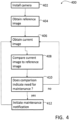
- FIG. 4 an example flow process 400 for a method of using image analytics to determine the need for elevator maintenance is shown.
- the process beings at 402 where at least one camera 210 is installed in the elevator system 101.
- the process 400 of FIG. 4 is described with reference to a single camera, but it is understood that multiple cameras may be used and the same process followed.
- a reference image is obtained from the camera 210. This may occur after installation and test of the elevator system 101, but before the elevator system 101 is operated in a normal mode of operation.
- the reference image may be obtained at any time, provided the elevator system 101 is known to be in good operating condition.
- the reference image may be obtained while a mechanic is on site working on the elevator system 101 and has deemed that all components of the elevator system 101 are in good working order.
- a partial reference image may be obtained.
- a new reference image may be obtained for components known to be in good working condition while other components may continue to use the pre-existing reference image.
- the reference image is transmitted to the image analysis system 320 and stored in memory 362.
- the camera and, in one embodiment, car position (based upon the information given by the car positioning system), properties associated with the reference image may be transmitted to the image analysis system 320 and stored in memory 362.
- the camera properties may include location (if the camera is mounted to the elevator car 101), point of view, lighting, focal length, etc.
- the system periodically acquires a current image at 406.
- the current image may be acquired on a time schedule (e.g., hourly, daily, weekly or when the elevator traffic is low). Additionally, the current image may be acquired in response to an event such as error logged in the elevator controller, a certain volume of usage of the elevator system 101, etc.
- the current image is transmitted to the image analysis system 320 and stored in memory 362.
- a current image is obtained using the same camera properties as the reference image.
- the current image and reference image may be obtained with slightly or substantially different camera properties.
- the image analysis system 320 compares the current image to the reference image to derive an image comparison value. This may be performed by comparing pixel values at the same locations in the current image and the reference image, or by any other known image comparison tool. A difference in pixel value at one location in the current image and the reference image indicates a change between the current image and the reference image. The absolute values of all the pixel differences between current image and the reference image may then be summed to generate an image comparison value. The pixel comparisons may be made, for example, based on change in color, change in brightness, etc.
- the image analysis system 320 may use one or more registration marks.
- the registration mark may be a physical mark (e.g., painted) positioned in the hoistway where the camera 210 is directed (e.g., on the pit floor, on the wall of the hoistway, etc.).
- a registration mark 506 in the form of a plus sign is used to align the reference image to the current image.
- the image analysis system 320 first ensures that the registration mark 506 in the reference image is superimposed with and aligned with the registration mark 506 of the current image. Once the images are aligned, the image analysis system 320 then compares the current image to the reference image as described herein.
- the image analysis system 320 determines if the image comparison value indicates a need for maintenance on the elevator system 101.
- the image analysis system 320 may compare the image comparison value to a threshold value to determine if there is a need for maintenance on the elevator system 101. If the image comparison value exceeds the threshold value, this indicates something is different between the current image and the reference image, which may indicate a need for maintenance.
- the threshold value may adjust over time, so that effects of dust, aging cameras, etc., would not result in a false positive indication of a need for maintenance on the elevator system 101.
- the image analysis system 320 may also determine if the differences between current image and the reference image are global or local.
- the process flows to 412 where a maintenance notification is initiated.
- the image analysis system 320 generates and sends the maintenance notification to the user device 330.
- the image analysis system 320 communicates with another system (e.g., an SMS or email server) to generate the maintenance notification.
- the maintenance notification may include a general notice that a maintenance event has been detected and is accompanied by the current image or both the current image and the reference image.
- FIG. 5 depicts an example reference image and current image transmitted to the user device 330 as part of a maintenance notification.
- the difference 500 between the reference image and current image is highlighted with an indicator 502 to aid the user in determining the cause of the maintenance notification.
- the user may then perform the appropriate maintenance operations on the elevator system 101.
- Embodiments facilitate maintenance of an elevator system by providing a maintenance notification only when needed. This eliminates the need to a user to regularly access the images from a camera and review the images.
- Embodiments may be implemented as one or more apparatuses, systems, and/or methods.
- instructions may be stored on one or more computer program products or computer-readable media, such as a transitory and/or non-transitory computer-readable medium.
- the instructions when executed, may cause an entity (e.g., a processor, apparatus or system) to perform one or more operations as described herein.
Landscapes
- Engineering & Computer Science (AREA)
- Quality & Reliability (AREA)
- Computer Vision & Pattern Recognition (AREA)
- Physics & Mathematics (AREA)
- General Physics & Mathematics (AREA)
- Theoretical Computer Science (AREA)
- Multimedia (AREA)
- Signal Processing (AREA)
- Indicating And Signalling Devices For Elevators (AREA)
- Maintenance And Inspection Apparatuses For Elevators (AREA)
- Cage And Drive Apparatuses For Elevators (AREA)
Description
- The subject matter disclosed herein generally relates to elevator systems and, more particularly, to the use of image analytics to facilitate elevator maintenance.
- Existing elevator systems may include a camera installed at the top or bottom of the elevator car. The image from the camera may be accessed by a user (e.g., a mechanic or service person) so that the user can perform an inspection of the elevator hoistway remotely, without needing to physically enter the hoistway.
-
US 2017/0015521 A1 discloses a device for monitoring a movement of at least one door (6, 16), in particular an elevator door (6, 16), comprising: at least one picture recording device (18) configured for recording a plurality of pictures of at least one portion of the at least one door (6, 16) during a movement of the at least one door (6, 16); at least one storing device (17) configured for storing a plurality of reference pictures; a comparison device (19), which is configured for comparing at least one of the recorded pictures with at least one of the reference pictures to determine a difference measure representative of the difference between the at least one stored picture and the at least one reference picture; and for issuing an alarm message when the difference measure exceeds a predetermined limit. -
US 2011/0067958 A1 discloses an elevator system and a method for maintenance of such an elevator system including a device for receiving a plurality of sensor signals. The device is mounted on at least one elevator car or at least one counterweight of the elevator system. The device includes at least one processor and at least one computer-readable data store in at least one device housing. A first sensor for generating a sensor signal is a position sensor and/or a speed sensor and/or an acceleration sensor which is mounted in and/or on the device housing. -
JP 2015-151207 A - Aspects of the invention may solve one or more problems of the art, with the solutions set forth in the independent claims and refinements recited in the dependent claims.
- According to an embodiment, an elevator system according to claim 1 is provided.
- Further embodiments of the elevator systems may include wherein the current image is acquired periodically.
- Further embodiments of the elevator systems may include wherein the current image is acquired in response to an event.
- Further embodiments of the elevator systems may include wherein the comparing the current image to the reference image generates an image comparison value.
- Further embodiments of the elevator systems may include wherein the image analysis system initiates the maintenance notification in response to the image comparison value exceeding a threshold value.
- Further embodiments of the elevator systems may include wherein the threshold value changes over time.
- Further embodiments of the elevator systems may include wherein the image comparison value is generated in response to differences between the current image and the reference image.
- Further embodiments of the elevator systems may include wherein the image comparison value is generated in response to pixel differences between the current image and the reference image.
- Further embodiments of the elevator systems may include wherein the maintenance notification includes the reference image.
- Further embodiments of the elevator systems may include wherein the camera is located at a top of the elevator hoistway, at a bottom of the elevator hoistway, on top of the elevator car, on a bottom of the elevator car or inside that elevator car.
- Further embodiments of the elevator systems may include wherein the reference image is obtained after installation and test of the elevator system and prior to operation of the elevator system in a normal mode of operation.
- According to another embodiment, a method according to claim 9 is provided.
- Further embodiments of the method may include wherein the current image is acquired periodically.
- Further embodiments of the method may include wherein the current image is acquired in response to an event.
- Further embodiments of the method may include wherein the comparing the current image to the reference image generates an image comparison value.
- Further embodiments of the method may include wherein the maintenance notification is initiated in response to the image comparison value exceeding a threshold value.
- Further embodiments of the method may include wherein the threshold value changes over time.
- Further embodiments of the method may include wherein the image comparison value is generated in response to differences between the current image and the reference image.
- Further embodiments of the method may include wherein the image comparison value is generated in response to pixel differences between the current image and the reference image.
- Further embodiments of the method may include wherein the maintenance notification includes the reference image.
- Further embodiments of the method may include wherein the reference image is obtained after installation and test of the elevator system and prior to operation of the elevator system in a normal mode of operation.
- Technical effects of embodiments include the ability to automatically detect the need for maintenance of an elevator system using images from a camera. Current images are repeatedly compared to a reference image to determine the need for maintenance of the elevator system.
- The foregoing features and elements may be combined in various combinations without exclusivity, unless expressly indicated otherwise. These features and elements as well as the operation thereof will become more apparent in light of the following description and the accompanying drawings. It should be understood, however, that the following description and drawings are intended to be illustrative and explanatory in nature and non-limiting.
- The subject matter is particularly pointed out and distinctly claimed at the conclusion of the specification. The foregoing and other features, and advantages of the present disclosure are apparent from the following detailed description taken in conjunction with the accompanying drawings in which:
-
FIG. 1 is a schematic illustration of an elevator system that may employ various embodiments of the present disclosure; -
FIG. 2 depicts cameras installed in an elevator system in an example embodiment; -
FIG. 3 depicts a system architecture in an example embodiment; -
FIG. 4 depicts a method of using image analytics to determine the need for elevator maintenance in an example embodiment; and -
FIG. 5 depicts a comparison between a reference image and a current image in an example embodiment. - As shown and described herein, various features of the disclosure will be presented. Various embodiments may have the same or similar features and thus the same or similar features may be labeled with the same reference numeral, but preceded by a different first number indicating the figure to which the feature is shown. Although similar reference numbers may be used in a generic sense, various embodiments will be described and various features may include changes, alterations, modifications, etc. as will be appreciated by those of skill in the art, whether explicitly described or otherwise would be appreciated by those of skill in the art.
-
FIG. 1 is a perspective view of anelevator system 101 including anelevator car 103, acounterweight 105, aroping 107, aguide rail 109, a machine 111, aposition encoder 113, and acontroller 115. Theelevator car 103 andcounterweight 105 are connected to each other by theroping 107. Theroping 107 may include or be configured as, for example, ropes, steel cables, and/or coated-steel belts. Thecounterweight 105 is configured to balance a load of theelevator car 103 and is configured to facilitate movement of theelevator car 103 concurrently and in an opposite direction with respect to thecounterweight 105 within anelevator hoistway 117 and along theguide rail 109. - The
roping 107 engages the machine 111, which is part of an overhead structure of theelevator system 101. The machine 111 is configured to control movement between theelevator car 103 and thecounterweight 105. Theposition encoder 113 may be mounted on an upper sheave of a speed-governor system 119 and may be configured to provide position signals related to a position of theelevator car 103 within theelevator hoistway 117. In other embodiments, theposition encoder 113 may be directly mounted to a moving component of the machine 111, or may be located in other positions and/or configurations as known in the art. - The
controller 115 is located, as shown, in acontroller room 121 of theelevator hoistway 117 and is configured to control the operation of theelevator system 101, and particularly theelevator car 103. For example, thecontroller 115 may provide drive signals to the machine 111 to control the acceleration, deceleration, leveling, stopping, etc. of theelevator car 103. Thecontroller 115 may also be configured to receive position signals from theposition encoder 113. When moving up or down within theelevator hoistway 117 alongguide rail 109, theelevator car 103 may stop at one ormore landings 125 as controlled by thecontroller 115. Although shown in acontroller room 121, those of skill in the art will appreciate that thecontroller 115 can be located and/or configured in other locations or positions within theelevator system 101. - The machine 111 may include a motor or similar driving mechanism. In accordance with embodiments of the disclosure, the machine 111 is configured to include an electrically driven motor. The power supply for the motor may be any power source, including a power grid, which, in combination with other components, is supplied to the motor.
- Although shown and described with a roping system, elevator systems that employ other methods and mechanisms of moving an elevator car within an elevator hoistway, including ropeless, hydraulic, and multi-car elevator systems, may employ embodiments of the present disclosure.
FIG. 1 is merely a non-limiting example presented for illustrative and explanatory purposes. -
FIG. 2 depicts theelevator system 101 in an example embodiment. In theelevator system 101 ofFIG. 2 , one ormore cameras 210 are mounted in the elevator system. Thecameras 210 may be mounted at the top of thehoistway 117, at the bottom of thehoistway 117, on top ofelevator car 103, on the bottom ofelevator car 103, or any other location in the elevator system, including within theelevator car 103. As described in further detail herein, images from the one ormore cameras 210 are analyzed to determine if maintenance on the elevator system is needed. -
FIG. 3 depicts a system architecture in an example embodiment. The one ormore cameras 210 acquire images and transmit the images to anetwork 310. The image from eachcamera 210 may comprise a single image or a sequence of images (e.g., video). Thenetwork 310 may include one or more of a wireline network; a wireless network; a local area network (LAN); and a wide area network (WAN), etc. Images from the one ormore cameras 210 are provided to animage analysis system 320 vianetwork 310. Theimage analysis system 320 may be implemented by theelevator controller 115. Theimage analysis system 320 may also be hosted on a remote computing system, such as a cloud computing platform. - The
image analysis system 320 may include aprocessor 360,memory 362 andcommunication module 364 as shown inFIG. 3 . Theprocessor 360 can be any type or combination of computer processors, such as a microprocessor, microcontroller, digital signal processor, application specific integrated circuit, programmable logic device, and/or field programmable gate array. Thememory 362 is an example of a non-transitory computer readable storage medium tangibly embodied in theimage analysis system 320 including executable instructions stored therein, for instance, as firmware.Processor 360 executes the intrusions inmemory 362 to implement the operations described herein. Thecommunication module 364 may implement one or more communication protocols to enable receiving images overnetwork 310 and sending notifications over the network to auser device 330. - The
user device 330 may receive a maintenance notification initiated by theimage analysis system 320. Themobile device 330 may include a device that is carried by a person, such as a smart phone, PDA, tablet, laptop, etc. Themobile device 330 may include wearable items, such as a smart watch, eyewear, etc. As described herein, theuser device 330 may receive a maintenance notification along with one or more images selected from the camera(s) 210. Theuser device 330 may also be able to access camera(s) 210 to obtain a real time images from the camera(s) 210. Theuser device 330 may also control characteristics of the camera such as field of view (pan, tilt), zoom, focus, lighting, etc. - Turning now to
FIG. 4 , anexample flow process 400 for a method of using image analytics to determine the need for elevator maintenance is shown. The process beings at 402 where at least onecamera 210 is installed in theelevator system 101. Theprocess 400 ofFIG. 4 is described with reference to a single camera, but it is understood that multiple cameras may be used and the same process followed. - At 404, a reference image is obtained from the
camera 210. This may occur after installation and test of theelevator system 101, but before theelevator system 101 is operated in a normal mode of operation. In one embodiment, the reference image may be obtained at any time, provided theelevator system 101 is known to be in good operating condition. For example, the reference image may be obtained while a mechanic is on site working on theelevator system 101 and has deemed that all components of theelevator system 101 are in good working order. In one embodiment, a partial reference image may be obtained. For example, a new reference image may be obtained for components known to be in good working condition while other components may continue to use the pre-existing reference image. The reference image is transmitted to theimage analysis system 320 and stored inmemory 362. Also, the camera and, in one embodiment, car position (based upon the information given by the car positioning system), properties associated with the reference image may be transmitted to theimage analysis system 320 and stored inmemory 362. The camera properties may include location (if the camera is mounted to the elevator car 101), point of view, lighting, focal length, etc. - Once the reference image is acquired, the system periodically acquires a current image at 406. The current image may be acquired on a time schedule (e.g., hourly, daily, weekly or when the elevator traffic is low). Additionally, the current image may be acquired in response to an event such as error logged in the elevator controller, a certain volume of usage of the
elevator system 101, etc. The current image is transmitted to theimage analysis system 320 and stored inmemory 362. In one embodiment, a current image is obtained using the same camera properties as the reference image. In one embodiment, the current image and reference image may be obtained with slightly or substantially different camera properties. - At 408, the
image analysis system 320 compares the current image to the reference image to derive an image comparison value. This may be performed by comparing pixel values at the same locations in the current image and the reference image, or by any other known image comparison tool. A difference in pixel value at one location in the current image and the reference image indicates a change between the current image and the reference image. The absolute values of all the pixel differences between current image and the reference image may then be summed to generate an image comparison value. The pixel comparisons may be made, for example, based on change in color, change in brightness, etc. - To compare the current image and the reference image, the
image analysis system 320 may use one or more registration marks. The registration mark may be a physical mark (e.g., painted) positioned in the hoistway where thecamera 210 is directed (e.g., on the pit floor, on the wall of the hoistway, etc.). Referring toFIG. 5 , aregistration mark 506 in the form of a plus sign is used to align the reference image to the current image. Using theregistration mark 506, theimage analysis system 320 first ensures that theregistration mark 506 in the reference image is superimposed with and aligned with theregistration mark 506 of the current image. Once the images are aligned, theimage analysis system 320 then compares the current image to the reference image as described herein. - At 410, the
image analysis system 320 determines if the image comparison value indicates a need for maintenance on theelevator system 101. Theimage analysis system 320 may compare the image comparison value to a threshold value to determine if there is a need for maintenance on theelevator system 101. If the image comparison value exceeds the threshold value, this indicates something is different between the current image and the reference image, which may indicate a need for maintenance. The threshold value may adjust over time, so that effects of dust, aging cameras, etc., would not result in a false positive indication of a need for maintenance on theelevator system 101. Theimage analysis system 320 may also determine if the differences between current image and the reference image are global or local. For example, if all pixels in the current image are 10% dimmer than those in the reference image, this suggests the difference is due to the camera, lens, dust, etc. If a localized group of pixels in the current image are 10% dimmer than those in the reference image, this suggests something has changed, such as an object has moved, debris, etc. - At 410, if the image comparison value does not indicate a need for maintenance, flow returns to 406 where the next current image is acquired. At 410, if the image comparison value does indicate a need for maintenance, the process flows to 412 where a maintenance notification is initiated. In an example embodiment, the
image analysis system 320 generates and sends the maintenance notification to theuser device 330. In other embodiments, theimage analysis system 320 communicates with another system (e.g., an SMS or email server) to generate the maintenance notification. - The maintenance notification may include a general notice that a maintenance event has been detected and is accompanied by the current image or both the current image and the reference image.
FIG. 5 depicts an example reference image and current image transmitted to theuser device 330 as part of a maintenance notification. Thedifference 500 between the reference image and current image is highlighted with anindicator 502 to aid the user in determining the cause of the maintenance notification. The user may then perform the appropriate maintenance operations on theelevator system 101. - Embodiments facilitate maintenance of an elevator system by providing a maintenance notification only when needed. This eliminates the need to a user to regularly access the images from a camera and review the images.
- Those of skill in the art will appreciate that various example embodiments are shown and described herein, each having certain features in the particular embodiments, but the present disclosure is not thus limited. That is, features of the various embodiments can be exchanged, altered, or otherwise combined in different combinations without departing from the scope of the present disclosure.
- Embodiments may be implemented as one or more apparatuses, systems, and/or methods. In some embodiments, instructions may be stored on one or more computer program products or computer-readable media, such as a transitory and/or non-transitory computer-readable medium. The instructions, when executed, may cause an entity (e.g., a processor, apparatus or system) to perform one or more operations as described herein.
- While the present disclosure has been described in detail in connection with only a limited number of embodiments, it should be readily understood that the present disclosure is not limited to such disclosed embodiments. Additionally, while various embodiments of the present disclosure have been described, it is to be understood that aspects of the present disclosure may include only some of the described embodiments.
- Accordingly, the present disclosure is not to be seen as limited by the foregoing description, but is only limited by the scope of the appended claims.
Claims (15)
- An elevator system (101), comprising:an elevator car (103) within an elevator hoistway (217);a plurality of cameras (210);a network (310); andan image analysis system (320) in communication with the cameras (210) over the network (310),wherein the cameras (210) provide a reference image to the image analysis system (320),wherein the cameras (210) provide a current image to the image analysis system (320),wherein the image analysis system (320) compares the current image to the reference image to detect a difference (500) between the current image to the reference image, andwherein the image analysis system (320) initiates a maintenance notification to a user device (330) in response to the comparing,characterized in that the maintenance notification includes the current image, wherein the current image is highlighted with an indicator (502) of a difference (500) between the current image and the reference image.
- The elevator system (101) of claim 1,wherein the current image is acquired periodically, orwherein the current image is acquired in response to an event.
- The elevator system (101) of claim 1-2, wherein the comparing the current image to the reference image generates an image comparison value.
- The elevator system (101) of any of claims 1-3, wherein the image analysis system (320) initiates the maintenance notification in response to the image comparison value exceeding a threshold value, wherein particularly the threshold value changes over time.
- The elevator system (101) of claim 3 or 4, wherein the image comparison value is generated in response to differences (500) between the current image and the reference image,
and/or
wherein the image comparison value is generated in response to pixel differences (500) between the current image and the reference image. - The elevator system (101) of any of claims 1-5, wherein the maintenance notification includes the reference image.
- The elevator system of any of claims 1-6, wherein the cameras are located at a top of the elevator hoistway, at a bottom of the elevator hoistway, on top of the elevator car, on a bottom of the elevator car and inside the elevator car.
- The elevator system (101) of any of claims 1-7, wherein the reference image is obtained after installation and test of the elevator system (101) and prior to operation of the elevator system (101) in a normal mode of operation.
- A method for determining that maintenance is needed in an elevator system (101), the method comprising:providing a reference image of the elevator system (101);providing a current image of the elevator system (101);comparing the current image to the reference image to detect a difference (500) between the current image to the reference image; andinitiating a maintenance notification to a user device in response to the comparing,characterized in that the maintenance notification includes the current image, wherein the current image is highlighted with an indicator (502) of a difference (500) between the current image and the reference image.
- The method of claim 9, wherein the current image is acquired periodically, or wherein the current image is acquired in response to an event.
- The method of claim 9 or 10, wherein the comparing the current image to the reference image generates an image comparison value,
wherein particularly the maintenance notification is initiated in response to the image comparison value exceeding a threshold value, wherein particularly the threshold value changes over time. - The method of claim 11, wherein the image comparison value is generated in response to differences (500) between the current image and the reference image,
and/or
wherein the image comparison value is generated in response to pixel differences (500) between the current image and the reference image. - The method of any of claims 9-12, wherein the maintenance notification includes the reference image.
- The method of any of claims 9-13, wherein the cameras are located at a top of the elevator hoistway, at a bottom of the elevator hoistway, on top of the elevator car, on a bottom of the elevator car and inside the elevator car.
- The method of any of claims 8-14, wherein the reference image is obtained after installation and test of the elevator system (101) and prior to operation of the elevator system (101) in a normal mode of operation.
Priority Applications (5)
| Application Number | Priority Date | Filing Date | Title |
|---|---|---|---|
| EP17305643.3A EP3409629B2 (en) | 2017-06-01 | 2017-06-01 | Image analytics for elevator maintenance |
| KR1020180061724A KR102572249B1 (en) | 2017-06-01 | 2018-05-30 | Image analytics for elevator maintenance |
| CN201810554798.2A CN108975112B (en) | 2017-06-01 | 2018-05-31 | Image analysis for elevator maintenance |
| US15/995,522 US11597632B2 (en) | 2017-06-01 | 2018-06-01 | Image analytics for elevator maintenance |
| US18/161,440 US20230174343A1 (en) | 2017-06-01 | 2023-01-30 | Image analytics for elevator maintenance |
Applications Claiming Priority (1)
| Application Number | Priority Date | Filing Date | Title |
|---|---|---|---|
| EP17305643.3A EP3409629B2 (en) | 2017-06-01 | 2017-06-01 | Image analytics for elevator maintenance |
Publications (3)
| Publication Number | Publication Date |
|---|---|
| EP3409629A1 EP3409629A1 (en) | 2018-12-05 |
| EP3409629B1 EP3409629B1 (en) | 2020-12-09 |
| EP3409629B2 true EP3409629B2 (en) | 2024-02-28 |
Family
ID=59034688
Family Applications (1)
| Application Number | Title | Priority Date | Filing Date |
|---|---|---|---|
| EP17305643.3A Active EP3409629B2 (en) | 2017-06-01 | 2017-06-01 | Image analytics for elevator maintenance |
Country Status (4)
| Country | Link |
|---|---|
| US (2) | US11597632B2 (en) |
| EP (1) | EP3409629B2 (en) |
| KR (1) | KR102572249B1 (en) |
| CN (1) | CN108975112B (en) |
Families Citing this family (20)
| Publication number | Priority date | Publication date | Assignee | Title |
|---|---|---|---|---|
| US10472207B2 (en) * | 2017-03-31 | 2019-11-12 | Otis Elevator Company | Passenger-initiated dynamic elevator service request |
| EP3409629B2 (en) * | 2017-06-01 | 2024-02-28 | Otis Elevator Company | Image analytics for elevator maintenance |
| EP3473574A1 (en) * | 2017-10-17 | 2019-04-24 | KONE Corporation | Diagnostics solution for elevators |
| US10961082B2 (en) * | 2018-01-02 | 2021-03-30 | Otis Elevator Company | Elevator inspection using automated sequencing of camera presets |
| US10941018B2 (en) * | 2018-01-04 | 2021-03-09 | Otis Elevator Company | Elevator auto-positioning for validating maintenance |
| EP3599204B1 (en) * | 2018-07-26 | 2022-01-12 | Otis Elevator Company | Elevator component inspection system and method |
| EP3693312A1 (en) * | 2018-09-27 | 2020-08-12 | Otis Elevator Company | Elevator system component analysis |
| CN109678023B (en) * | 2019-02-27 | 2020-08-11 | 广州广日电梯工业有限公司 | Elevator monitoring method and device based on night imaging technology |
| CN110002307B (en) * | 2019-03-25 | 2024-07-02 | 上海富士电梯有限公司 | Elevator maintenance protection system based on image recognition |
| KR102036785B1 (en) * | 2019-06-24 | 2019-11-26 | 김길곤 | Method and apparatus for controlling elevator maintenance and repair process |
| KR102059305B1 (en) * | 2019-09-09 | 2019-12-24 | 최한성 | Method and apparatus for controlling elevator panel manufacturing process |
| US20210183039A1 (en) * | 2019-12-13 | 2021-06-17 | Lindsey Firesense, Llc | System and method of debris detection and integrity validation for right-of-way based infrastructure |
| CN111611546B (en) * | 2020-05-18 | 2023-06-20 | 南京市特种设备安全监督检验研究院 | Elevator on-demand maintenance work quality evaluation method based on Internet of things data extraction and calculation |
| US11544931B2 (en) | 2020-05-26 | 2023-01-03 | Otis Elevator Company | Machine learning based human activity detection and classification in first and third person videos |
| CN111874768B (en) * | 2020-07-29 | 2022-06-21 | 日立楼宇技术(广州)有限公司 | Method, device, equipment and system for detecting installation state of elevator component |
| CN112573312B (en) * | 2020-12-03 | 2023-02-28 | 日立楼宇技术(广州)有限公司 | Elevator car position determining method and device, elevator system and storage medium |
| CN112465812B (en) * | 2020-12-16 | 2023-08-11 | 阳光智维科技股份有限公司 | Dust detection device and method for photovoltaic module |
| CN112819782B (en) * | 2021-01-29 | 2023-03-24 | 菱王电梯有限公司 | Self-learning car vision analysis method |
| KR102315203B1 (en) * | 2021-04-08 | 2021-10-19 | 유영진 | Elevator maintenance device |
| WO2024184575A1 (en) * | 2023-03-06 | 2024-09-12 | Kone Corporation | Condition monitoring inside an elevator shaft of an elevator system |
Citations (3)
| Publication number | Priority date | Publication date | Assignee | Title |
|---|---|---|---|---|
| JP2001006071A (en) † | 1999-06-24 | 2001-01-12 | Hitachi Building Systems Co Ltd | Remote monitoring device for elevator |
| JP2008087898A (en) † | 2006-09-29 | 2008-04-17 | Toshiba Elevator Co Ltd | Function variable type remote monitoring system and remote monitoring method for elevator |
| US20160034784A1 (en) † | 2014-08-01 | 2016-02-04 | Ricoh Company, Ltd. | Abnormality detection apparatus, abnormality detection method, and recording medium storing abnormality detection program |
Family Cites Families (48)
| Publication number | Priority date | Publication date | Assignee | Title |
|---|---|---|---|---|
| JPH1059636A (en) | 1996-08-20 | 1998-03-03 | Hitachi Building Syst Co Ltd | Diagnostic device for elevator by image |
| JP2001048433A (en) | 1999-08-06 | 2001-02-20 | Hitachi Building Systems Co Ltd | Picture device of elevator |
| SG96681A1 (en) | 2001-02-20 | 2003-06-16 | Inventio Ag | Method of generating hoistway information to serve an elevator control |
| FI117432B (en) | 2002-02-05 | 2006-10-13 | Kone Corp | Procedure and arrangement for remote monitoring of an elevator |
| ZA200307740B (en) * | 2002-10-29 | 2004-07-02 | Inventio Ag | Device and method for remote maintenance of a lift. |
| DE10339314B3 (en) * | 2003-08-27 | 2005-04-21 | Fraunhofer-Gesellschaft zur Förderung der angewandten Forschung e.V. | Method for display control of different information in a vehicle and opto-acoustic information unit |
| US7401684B2 (en) * | 2004-07-08 | 2008-07-22 | Mitsubishi Denki Kabushiki Kaisha | Automatic announcing device for an elevator |
| MX2007005538A (en) * | 2004-11-09 | 2007-05-21 | Inventio Ag | Maintenance method and device for an elevator or escalator installation. |
| FR2880167B1 (en) * | 2004-12-23 | 2009-05-08 | Celec Conception Electronique | PRESENCE AND MOTION DETECTION METHOD FOR DOOR AUTOMATISMS AND DOOR AUTOMATISMS USING SUCH A METHOD |
| US20080198117A1 (en) * | 2005-03-11 | 2008-08-21 | Takeshi Kumakura | Display Device, Liquid Crystal Monitor, Liquid Crystal Television Receiver, and Display Method |
| JP4176818B2 (en) * | 2005-03-15 | 2008-11-05 | シャープ株式会社 | Display device, display device adjustment method, image display monitor, and television receiver |
| US8896216B2 (en) * | 2005-06-28 | 2014-11-25 | Seoul Viosys Co., Ltd. | Illumination system |
| CN101305395A (en) * | 2005-11-10 | 2008-11-12 | 皇家飞利浦电子股份有限公司 | Adaptive point-based elastic image registration |
| EP2250114A1 (en) * | 2008-03-06 | 2010-11-17 | Inventio AG | Lift system and method for servicing such a lift system |
| WO2010092619A1 (en) | 2009-02-12 | 2010-08-19 | Otis Elevator Company | Elevator tension member image inspection device |
| JP2010202397A (en) | 2009-03-05 | 2010-09-16 | Toshiba Elevator Co Ltd | Elevator system |
| KR101387042B1 (en) * | 2010-08-20 | 2014-04-29 | 오티스 엘리베이터 컴파니 | Remote controlled passenger conveyor and method for remotely controlling a passenger conveyor |
| JP2012180168A (en) | 2011-03-01 | 2012-09-20 | Toshiba Elevator Co Ltd | Imaging apparatus for elevator maintenance and inspection |
| JP5527475B2 (en) | 2011-03-16 | 2014-06-18 | 三菱電機株式会社 | Elevator control device |
| JP2013028440A (en) * | 2011-07-29 | 2013-02-07 | Mitsubishi Electric Building Techno Service Co Ltd | Method of inspecting in-car camera of elevator |
| JP5814734B2 (en) | 2011-10-11 | 2015-11-17 | 三菱電機ビルテクノサービス株式会社 | Gap size inspection device for elevator landing device and clearance size inspection method for elevator landing device |
| CN103327275B (en) * | 2013-05-08 | 2016-06-29 | 深圳市绎立锐光科技开发有限公司 | Display uniformity compensation method, optic modulating device, signal processor and optical projection system |
| JP6132690B2 (en) | 2013-07-19 | 2017-05-24 | 三菱電機ビルテクノサービス株式会社 | Elevator long object inspection device and elevator long object inspection method |
| JP5743346B2 (en) | 2013-08-08 | 2015-07-01 | 東芝エレベータ株式会社 | ELEVATOR SYSTEM, ELEVATOR CONTROL DEVICE USED FOR SAME, AND ELEVATOR CONTROL METHOD |
| JP6163095B2 (en) | 2013-12-09 | 2017-07-12 | 株式会社日立ビルシステム | Monitoring system in elevator hoistway |
| JP6109097B2 (en) * | 2014-02-12 | 2017-04-05 | 三菱電機ビルテクノサービス株式会社 | Elevator pit status confirmation system |
| US20170015521A1 (en) * | 2014-03-19 | 2017-01-19 | Mustapha Toutaoui | Method and device for monitoring the movement of at least one door, in particular an elevator door |
| TWI675792B (en) | 2014-12-16 | 2019-11-01 | 瑞士商伊文修股份有限公司 | Position-determination system for an elevator and elevator with a position-determination system |
| WO2016120373A1 (en) | 2015-01-30 | 2016-08-04 | Thyssenkrupp Elevator Ag | Real-time rope/cable/belt sway monitoring system for elevator application |
| CN104635408B (en) * | 2015-03-11 | 2016-04-20 | 青岛海信电器股份有限公司 | A kind of method of projection arrangement, optical projection system and adjustment projection systems project brightness |
| KR101878649B1 (en) * | 2015-05-26 | 2018-07-16 | 크라운 이큅먼트 코포레이션 | Systems and Methods for Material Handling Vehicle Odometry Calibration |
| DE102015209983A1 (en) * | 2015-05-29 | 2016-12-01 | Conti Temic Microelectronic Gmbh | Control device for a vehicle and method |
| CN108350650B (en) * | 2015-10-21 | 2021-06-22 | 比伯拉赫利勃海尔零部件有限公司 | Device for identifying replacement state of high-strength fiber rope |
| JP6092433B1 (en) * | 2016-01-13 | 2017-03-08 | 東芝エレベータ株式会社 | Elevator boarding detection system |
| TWI581665B (en) * | 2016-02-18 | 2017-05-01 | 晶睿通訊股份有限公司 | Lighting Device And Detection Method Thereof |
| US10308477B2 (en) * | 2016-10-24 | 2019-06-04 | Echostar Technologies International Corporation | Smart elevator movement |
| CN106395538B (en) | 2016-12-06 | 2019-03-12 | 宁波永良电梯技术发展有限公司 | Lift car stops detection system and its detection method |
| US10544007B2 (en) * | 2017-03-23 | 2020-01-28 | International Business Machines Corporation | Risk-aware management of elevator operations |
| EP3409629B2 (en) * | 2017-06-01 | 2024-02-28 | Otis Elevator Company | Image analytics for elevator maintenance |
| CN107045863B (en) * | 2017-06-26 | 2018-02-16 | 惠科股份有限公司 | Gray scale adjusting method and device of display panel |
| CN107610143B (en) * | 2017-09-29 | 2020-05-19 | 上海天马有机发光显示技术有限公司 | Image processing method, image processing apparatus, image processing system, and display apparatus |
| CN107644410B (en) * | 2017-09-29 | 2020-05-19 | 上海天马有机发光显示技术有限公司 | Image processing method, image processing apparatus, image processing system, and display apparatus |
| EP3473574A1 (en) * | 2017-10-17 | 2019-04-24 | KONE Corporation | Diagnostics solution for elevators |
| US10870556B2 (en) * | 2017-12-12 | 2020-12-22 | Otis Elevator Company | Method and system for detecting elevator car operating panel condition |
| US10941018B2 (en) * | 2018-01-04 | 2021-03-09 | Otis Elevator Company | Elevator auto-positioning for validating maintenance |
| US10726779B2 (en) * | 2018-01-29 | 2020-07-28 | Apple Inc. | Electronic devices with displays having integrated display-light sensors |
| EP3693312A1 (en) * | 2018-09-27 | 2020-08-12 | Otis Elevator Company | Elevator system component analysis |
| US11906445B2 (en) * | 2018-10-10 | 2024-02-20 | Goodrich Corporation | Automated defect detection for wire rope using image processing techniques |
-
2017
- 2017-06-01 EP EP17305643.3A patent/EP3409629B2/en active Active
-
2018
- 2018-05-30 KR KR1020180061724A patent/KR102572249B1/en active IP Right Grant
- 2018-05-31 CN CN201810554798.2A patent/CN108975112B/en active Active
- 2018-06-01 US US15/995,522 patent/US11597632B2/en active Active
-
2023
- 2023-01-30 US US18/161,440 patent/US20230174343A1/en active Pending
Patent Citations (3)
| Publication number | Priority date | Publication date | Assignee | Title |
|---|---|---|---|---|
| JP2001006071A (en) † | 1999-06-24 | 2001-01-12 | Hitachi Building Systems Co Ltd | Remote monitoring device for elevator |
| JP2008087898A (en) † | 2006-09-29 | 2008-04-17 | Toshiba Elevator Co Ltd | Function variable type remote monitoring system and remote monitoring method for elevator |
| US20160034784A1 (en) † | 2014-08-01 | 2016-02-04 | Ricoh Company, Ltd. | Abnormality detection apparatus, abnormality detection method, and recording medium storing abnormality detection program |
Also Published As
| Publication number | Publication date |
|---|---|
| EP3409629B1 (en) | 2020-12-09 |
| CN108975112B (en) | 2021-07-13 |
| US20180346286A1 (en) | 2018-12-06 |
| US11597632B2 (en) | 2023-03-07 |
| US20230174343A1 (en) | 2023-06-08 |
| KR102572249B1 (en) | 2023-08-29 |
| EP3409629A1 (en) | 2018-12-05 |
| KR20180131978A (en) | 2018-12-11 |
| CN108975112A (en) | 2018-12-11 |
Similar Documents
| Publication | Publication Date | Title |
|---|---|---|
| EP3409629B2 (en) | Image analytics for elevator maintenance | |
| EP2867150B1 (en) | Position and load measurement system for an elevator | |
| US11518655B2 (en) | Elevator component inspection systems | |
| KR101266761B1 (en) | System and methode to monitoring the elevator | |
| KR101567773B1 (en) | Remote control system for dangerous facility and controlling method | |
| JP5516344B2 (en) | Traffic vehicle monitoring system and vehicle monitoring camera | |
| JP6219247B2 (en) | Video surveillance device | |
| JP2011068440A (en) | Elevator monitoring device, elevator monitoring method and elevator remote monitoring system | |
| CN108861923B (en) | Automatic elevator inspection system and method | |
| CN112520528B (en) | Automatic monitoring elevator fault detection system and detection method thereof | |
| JP2008001494A (en) | Recovery device for elevator at the time of earthquake | |
| KR101266775B1 (en) | System and methode to monitoring the elevator | |
| EP3872018B1 (en) | An elevator monitoring system | |
| KR20210013287A (en) | Inspection device with the function of presenting the internal condition of the elevator hoistway | |
| JP6140436B2 (en) | Shooting system | |
| JP2015036333A (en) | Abnormal stop notification system for elevator | |
| JP6624522B2 (en) | Remote monitoring system for lifting equipment | |
| EP3650390A1 (en) | Conveyance system video analytics | |
| JP2016060565A (en) | Lighting detection device for inside-car button | |
| WO2022248580A1 (en) | Method and system for monitoring the technical condition of the interior of a shaft system of an elevator installation | |
| WO2007039750A2 (en) | Elevator floor levelling sensor system | |
| JP6687690B2 (en) | Elevator control system | |
| JP6346881B2 (en) | Image monitoring apparatus, image monitoring system, and image monitoring method | |
| JP4574307B2 (en) | Movable home fence system | |
| CN211264419U (en) | Intrusion detection system |
Legal Events
| Date | Code | Title | Description |
|---|---|---|---|
| PUAI | Public reference made under article 153(3) epc to a published international application that has entered the european phase |
Free format text: ORIGINAL CODE: 0009012 |
|
| STAA | Information on the status of an ep patent application or granted ep patent |
Free format text: STATUS: THE APPLICATION HAS BEEN PUBLISHED |
|
| AK | Designated contracting states |
Kind code of ref document: A1 Designated state(s): AL AT BE BG CH CY CZ DE DK EE ES FI FR GB GR HR HU IE IS IT LI LT LU LV MC MK MT NL NO PL PT RO RS SE SI SK SM TR |
|
| AX | Request for extension of the european patent |
Extension state: BA ME |
|
| STAA | Information on the status of an ep patent application or granted ep patent |
Free format text: STATUS: REQUEST FOR EXAMINATION WAS MADE |
|
| 17P | Request for examination filed |
Effective date: 20190503 |
|
| RBV | Designated contracting states (corrected) |
Designated state(s): AL AT BE BG CH CY CZ DE DK EE ES FI FR GB GR HR HU IE IS IT LI LT LU LV MC MK MT NL NO PL PT RO RS SE SI SK SM TR |
|
| GRAP | Despatch of communication of intention to grant a patent |
Free format text: ORIGINAL CODE: EPIDOSNIGR1 |
|
| STAA | Information on the status of an ep patent application or granted ep patent |
Free format text: STATUS: GRANT OF PATENT IS INTENDED |
|
| INTG | Intention to grant announced |
Effective date: 20200715 |
|
| GRAS | Grant fee paid |
Free format text: ORIGINAL CODE: EPIDOSNIGR3 |
|
| GRAA | (expected) grant |
Free format text: ORIGINAL CODE: 0009210 |
|
| STAA | Information on the status of an ep patent application or granted ep patent |
Free format text: STATUS: THE PATENT HAS BEEN GRANTED |
|
| AK | Designated contracting states |
Kind code of ref document: B1 Designated state(s): AL AT BE BG CH CY CZ DE DK EE ES FI FR GB GR HR HU IE IS IT LI LT LU LV MC MK MT NL NO PL PT RO RS SE SI SK SM TR |
|
| REG | Reference to a national code |
Ref country code: GB Ref legal event code: FG4D |
|
| REG | Reference to a national code |
Ref country code: AT Ref legal event code: REF Ref document number: 1343229 Country of ref document: AT Kind code of ref document: T Effective date: 20201215 Ref country code: CH Ref legal event code: EP |
|
| REG | Reference to a national code |
Ref country code: DE Ref legal event code: R096 Ref document number: 602017029181 Country of ref document: DE |
|
| REG | Reference to a national code |
Ref country code: IE Ref legal event code: FG4D |
|
| PG25 | Lapsed in a contracting state [announced via postgrant information from national office to epo] |
Ref country code: RS Free format text: LAPSE BECAUSE OF FAILURE TO SUBMIT A TRANSLATION OF THE DESCRIPTION OR TO PAY THE FEE WITHIN THE PRESCRIBED TIME-LIMIT Effective date: 20201209 Ref country code: NO Free format text: LAPSE BECAUSE OF FAILURE TO SUBMIT A TRANSLATION OF THE DESCRIPTION OR TO PAY THE FEE WITHIN THE PRESCRIBED TIME-LIMIT Effective date: 20210309 Ref country code: FI Free format text: LAPSE BECAUSE OF FAILURE TO SUBMIT A TRANSLATION OF THE DESCRIPTION OR TO PAY THE FEE WITHIN THE PRESCRIBED TIME-LIMIT Effective date: 20201209 Ref country code: GR Free format text: LAPSE BECAUSE OF FAILURE TO SUBMIT A TRANSLATION OF THE DESCRIPTION OR TO PAY THE FEE WITHIN THE PRESCRIBED TIME-LIMIT Effective date: 20210310 |
|
| REG | Reference to a national code |
Ref country code: AT Ref legal event code: MK05 Ref document number: 1343229 Country of ref document: AT Kind code of ref document: T Effective date: 20201209 |
|
| PG25 | Lapsed in a contracting state [announced via postgrant information from national office to epo] |
Ref country code: SE Free format text: LAPSE BECAUSE OF FAILURE TO SUBMIT A TRANSLATION OF THE DESCRIPTION OR TO PAY THE FEE WITHIN THE PRESCRIBED TIME-LIMIT Effective date: 20201209 Ref country code: BG Free format text: LAPSE BECAUSE OF FAILURE TO SUBMIT A TRANSLATION OF THE DESCRIPTION OR TO PAY THE FEE WITHIN THE PRESCRIBED TIME-LIMIT Effective date: 20210309 Ref country code: LV Free format text: LAPSE BECAUSE OF FAILURE TO SUBMIT A TRANSLATION OF THE DESCRIPTION OR TO PAY THE FEE WITHIN THE PRESCRIBED TIME-LIMIT Effective date: 20201209 |
|
| REG | Reference to a national code |
Ref country code: NL Ref legal event code: MP Effective date: 20201209 |
|
| PG25 | Lapsed in a contracting state [announced via postgrant information from national office to epo] |
Ref country code: NL Free format text: LAPSE BECAUSE OF FAILURE TO SUBMIT A TRANSLATION OF THE DESCRIPTION OR TO PAY THE FEE WITHIN THE PRESCRIBED TIME-LIMIT Effective date: 20201209 Ref country code: HR Free format text: LAPSE BECAUSE OF FAILURE TO SUBMIT A TRANSLATION OF THE DESCRIPTION OR TO PAY THE FEE WITHIN THE PRESCRIBED TIME-LIMIT Effective date: 20201209 |
|
| REG | Reference to a national code |
Ref country code: LT Ref legal event code: MG9D |
|
| PG25 | Lapsed in a contracting state [announced via postgrant information from national office to epo] |
Ref country code: RO Free format text: LAPSE BECAUSE OF FAILURE TO SUBMIT A TRANSLATION OF THE DESCRIPTION OR TO PAY THE FEE WITHIN THE PRESCRIBED TIME-LIMIT Effective date: 20201209 Ref country code: SK Free format text: LAPSE BECAUSE OF FAILURE TO SUBMIT A TRANSLATION OF THE DESCRIPTION OR TO PAY THE FEE WITHIN THE PRESCRIBED TIME-LIMIT Effective date: 20201209 Ref country code: PT Free format text: LAPSE BECAUSE OF FAILURE TO SUBMIT A TRANSLATION OF THE DESCRIPTION OR TO PAY THE FEE WITHIN THE PRESCRIBED TIME-LIMIT Effective date: 20210409 Ref country code: CZ Free format text: LAPSE BECAUSE OF FAILURE TO SUBMIT A TRANSLATION OF THE DESCRIPTION OR TO PAY THE FEE WITHIN THE PRESCRIBED TIME-LIMIT Effective date: 20201209 Ref country code: EE Free format text: LAPSE BECAUSE OF FAILURE TO SUBMIT A TRANSLATION OF THE DESCRIPTION OR TO PAY THE FEE WITHIN THE PRESCRIBED TIME-LIMIT Effective date: 20201209 Ref country code: LT Free format text: LAPSE BECAUSE OF FAILURE TO SUBMIT A TRANSLATION OF THE DESCRIPTION OR TO PAY THE FEE WITHIN THE PRESCRIBED TIME-LIMIT Effective date: 20201209 Ref country code: SM Free format text: LAPSE BECAUSE OF FAILURE TO SUBMIT A TRANSLATION OF THE DESCRIPTION OR TO PAY THE FEE WITHIN THE PRESCRIBED TIME-LIMIT Effective date: 20201209 |
|
| PG25 | Lapsed in a contracting state [announced via postgrant information from national office to epo] |
Ref country code: AT Free format text: LAPSE BECAUSE OF FAILURE TO SUBMIT A TRANSLATION OF THE DESCRIPTION OR TO PAY THE FEE WITHIN THE PRESCRIBED TIME-LIMIT Effective date: 20201209 Ref country code: PL Free format text: LAPSE BECAUSE OF FAILURE TO SUBMIT A TRANSLATION OF THE DESCRIPTION OR TO PAY THE FEE WITHIN THE PRESCRIBED TIME-LIMIT Effective date: 20201209 |
|
| REG | Reference to a national code |
Ref country code: DE Ref legal event code: R026 Ref document number: 602017029181 Country of ref document: DE |
|
| PLBI | Opposition filed |
Free format text: ORIGINAL CODE: 0009260 |
|
| PLAX | Notice of opposition and request to file observation + time limit sent |
Free format text: ORIGINAL CODE: EPIDOSNOBS2 |
|
| PG25 | Lapsed in a contracting state [announced via postgrant information from national office to epo] |
Ref country code: IS Free format text: LAPSE BECAUSE OF FAILURE TO SUBMIT A TRANSLATION OF THE DESCRIPTION OR TO PAY THE FEE WITHIN THE PRESCRIBED TIME-LIMIT Effective date: 20210409 |
|
| 26 | Opposition filed |
Opponent name: KONE CORPORATION Effective date: 20210906 |
|
| PG25 | Lapsed in a contracting state [announced via postgrant information from national office to epo] |
Ref country code: AL Free format text: LAPSE BECAUSE OF FAILURE TO SUBMIT A TRANSLATION OF THE DESCRIPTION OR TO PAY THE FEE WITHIN THE PRESCRIBED TIME-LIMIT Effective date: 20201209 Ref country code: IT Free format text: LAPSE BECAUSE OF FAILURE TO SUBMIT A TRANSLATION OF THE DESCRIPTION OR TO PAY THE FEE WITHIN THE PRESCRIBED TIME-LIMIT Effective date: 20201209 |
|
| PG25 | Lapsed in a contracting state [announced via postgrant information from national office to epo] |
Ref country code: SI Free format text: LAPSE BECAUSE OF FAILURE TO SUBMIT A TRANSLATION OF THE DESCRIPTION OR TO PAY THE FEE WITHIN THE PRESCRIBED TIME-LIMIT Effective date: 20201209 Ref country code: DK Free format text: LAPSE BECAUSE OF FAILURE TO SUBMIT A TRANSLATION OF THE DESCRIPTION OR TO PAY THE FEE WITHIN THE PRESCRIBED TIME-LIMIT Effective date: 20201209 |
|
| PG25 | Lapsed in a contracting state [announced via postgrant information from national office to epo] |
Ref country code: MC Free format text: LAPSE BECAUSE OF FAILURE TO SUBMIT A TRANSLATION OF THE DESCRIPTION OR TO PAY THE FEE WITHIN THE PRESCRIBED TIME-LIMIT Effective date: 20201209 Ref country code: ES Free format text: LAPSE BECAUSE OF FAILURE TO SUBMIT A TRANSLATION OF THE DESCRIPTION OR TO PAY THE FEE WITHIN THE PRESCRIBED TIME-LIMIT Effective date: 20201209 |
|
| REG | Reference to a national code |
Ref country code: CH Ref legal event code: PL |
|
| GBPC | Gb: european patent ceased through non-payment of renewal fee |
Effective date: 20210601 |
|
| PLBB | Reply of patent proprietor to notice(s) of opposition received |
Free format text: ORIGINAL CODE: EPIDOSNOBS3 |
|
| REG | Reference to a national code |
Ref country code: BE Ref legal event code: MM Effective date: 20210630 |
|
| PG25 | Lapsed in a contracting state [announced via postgrant information from national office to epo] |
Ref country code: LU Free format text: LAPSE BECAUSE OF NON-PAYMENT OF DUE FEES Effective date: 20210601 |
|
| PG25 | Lapsed in a contracting state [announced via postgrant information from national office to epo] |
Ref country code: LI Free format text: LAPSE BECAUSE OF NON-PAYMENT OF DUE FEES Effective date: 20210630 Ref country code: IE Free format text: LAPSE BECAUSE OF NON-PAYMENT OF DUE FEES Effective date: 20210601 Ref country code: GB Free format text: LAPSE BECAUSE OF NON-PAYMENT OF DUE FEES Effective date: 20210601 Ref country code: CH Free format text: LAPSE BECAUSE OF NON-PAYMENT OF DUE FEES Effective date: 20210630 |
|
| PG25 | Lapsed in a contracting state [announced via postgrant information from national office to epo] |
Ref country code: IS Free format text: LAPSE BECAUSE OF FAILURE TO SUBMIT A TRANSLATION OF THE DESCRIPTION OR TO PAY THE FEE WITHIN THE PRESCRIBED TIME-LIMIT Effective date: 20210409 |
|
| PG25 | Lapsed in a contracting state [announced via postgrant information from national office to epo] |
Ref country code: BE Free format text: LAPSE BECAUSE OF NON-PAYMENT OF DUE FEES Effective date: 20210630 |
|
| APBM | Appeal reference recorded |
Free format text: ORIGINAL CODE: EPIDOSNREFNO |
|
| APBP | Date of receipt of notice of appeal recorded |
Free format text: ORIGINAL CODE: EPIDOSNNOA2O |
|
| APAH | Appeal reference modified |
Free format text: ORIGINAL CODE: EPIDOSCREFNO |
|
| PG25 | Lapsed in a contracting state [announced via postgrant information from national office to epo] |
Ref country code: CY Free format text: LAPSE BECAUSE OF FAILURE TO SUBMIT A TRANSLATION OF THE DESCRIPTION OR TO PAY THE FEE WITHIN THE PRESCRIBED TIME-LIMIT Effective date: 20201209 |
|
| PG25 | Lapsed in a contracting state [announced via postgrant information from national office to epo] |
Ref country code: HU Free format text: LAPSE BECAUSE OF FAILURE TO SUBMIT A TRANSLATION OF THE DESCRIPTION OR TO PAY THE FEE WITHIN THE PRESCRIBED TIME-LIMIT; INVALID AB INITIO Effective date: 20170601 |
|
| APBU | Appeal procedure closed |
Free format text: ORIGINAL CODE: EPIDOSNNOA9O |
|
| PUAH | Patent maintained in amended form |
Free format text: ORIGINAL CODE: 0009272 |
|
| STAA | Information on the status of an ep patent application or granted ep patent |
Free format text: STATUS: PATENT MAINTAINED AS AMENDED |
|
| 27A | Patent maintained in amended form |
Effective date: 20240228 |
|
| AK | Designated contracting states |
Kind code of ref document: B2 Designated state(s): AL AT BE BG CH CY CZ DE DK EE ES FI FR GB GR HR HU IE IS IT LI LT LU LV MC MK MT NL NO PL PT RO RS SE SI SK SM TR |
|
| REG | Reference to a national code |
Ref country code: DE Ref legal event code: R102 Ref document number: 602017029181 Country of ref document: DE |
|
| PG25 | Lapsed in a contracting state [announced via postgrant information from national office to epo] |
Ref country code: MK Free format text: LAPSE BECAUSE OF FAILURE TO SUBMIT A TRANSLATION OF THE DESCRIPTION OR TO PAY THE FEE WITHIN THE PRESCRIBED TIME-LIMIT Effective date: 20201209 |
|
| PGFP | Annual fee paid to national office [announced via postgrant information from national office to epo] |
Ref country code: DE Payment date: 20240521 Year of fee payment: 8 |
|
| PGFP | Annual fee paid to national office [announced via postgrant information from national office to epo] |
Ref country code: FR Payment date: 20240522 Year of fee payment: 8 |