EP3365268B1 - Fuel distributor, the hydraulic compartment of which is equipped with an additive injection device - Google Patents
Fuel distributor, the hydraulic compartment of which is equipped with an additive injection device Download PDFInfo
- Publication number
- EP3365268B1 EP3365268B1 EP16790717.9A EP16790717A EP3365268B1 EP 3365268 B1 EP3365268 B1 EP 3365268B1 EP 16790717 A EP16790717 A EP 16790717A EP 3365268 B1 EP3365268 B1 EP 3365268B1
- Authority
- EP
- European Patent Office
- Prior art keywords
- additive
- flange
- motor
- fuel
- wall
- Prior art date
- Legal status (The legal status is an assumption and is not a legal conclusion. Google has not performed a legal analysis and makes no representation as to the accuracy of the status listed.)
- Active
Links
- 239000000654 additive Substances 0.000 title claims description 87
- 230000000996 additive effect Effects 0.000 title claims description 85
- 238000002347 injection Methods 0.000 title claims description 79
- 239000007924 injection Substances 0.000 title claims description 79
- 239000000446 fuel Substances 0.000 title claims description 76
- 238000009826 distribution Methods 0.000 claims description 22
- 230000002093 peripheral effect Effects 0.000 claims description 16
- 238000005086 pumping Methods 0.000 claims description 11
- 230000000284 resting effect Effects 0.000 claims description 3
- 230000001276 controlling effect Effects 0.000 claims description 2
- 230000001105 regulatory effect Effects 0.000 claims description 2
- 239000007788 liquid Substances 0.000 description 5
- 238000004880 explosion Methods 0.000 description 4
- 238000007872 degassing Methods 0.000 description 3
- 239000002360 explosive Substances 0.000 description 3
- 239000012530 fluid Substances 0.000 description 3
- 210000004907 gland Anatomy 0.000 description 3
- 238000012423 maintenance Methods 0.000 description 3
- 239000000919 ceramic Substances 0.000 description 2
- 238000004891 communication Methods 0.000 description 2
- 238000009429 electrical wiring Methods 0.000 description 2
- 230000005484 gravity Effects 0.000 description 2
- 230000005355 Hall effect Effects 0.000 description 1
- 229910052782 aluminium Inorganic materials 0.000 description 1
- XAGFODPZIPBFFR-UHFFFAOYSA-N aluminium Chemical compound [Al] XAGFODPZIPBFFR-UHFFFAOYSA-N 0.000 description 1
- 239000003638 chemical reducing agent Substances 0.000 description 1
- 238000002485 combustion reaction Methods 0.000 description 1
- 230000007547 defect Effects 0.000 description 1
- 238000006073 displacement reaction Methods 0.000 description 1
- 238000005461 lubrication Methods 0.000 description 1
- 238000004519 manufacturing process Methods 0.000 description 1
- 238000005259 measurement Methods 0.000 description 1
- 229910052751 metal Inorganic materials 0.000 description 1
- 239000002184 metal Substances 0.000 description 1
- 239000000203 mixture Substances 0.000 description 1
- 230000003287 optical effect Effects 0.000 description 1
- 230000001681 protective effect Effects 0.000 description 1
- 238000003860 storage Methods 0.000 description 1
- 238000011144 upstream manufacturing Methods 0.000 description 1
Images


Classifications
-
- B—PERFORMING OPERATIONS; TRANSPORTING
- B67—OPENING, CLOSING OR CLEANING BOTTLES, JARS OR SIMILAR CONTAINERS; LIQUID HANDLING
- B67D—DISPENSING, DELIVERING OR TRANSFERRING LIQUIDS, NOT OTHERWISE PROVIDED FOR
- B67D7/00—Apparatus or devices for transferring liquids from bulk storage containers or reservoirs into vehicles or into portable containers, e.g. for retail sale purposes
- B67D7/06—Details or accessories
- B67D7/74—Devices for mixing two or more different liquids to be transferred
- B67D7/743—Devices for mixing two or more different liquids to be transferred electrically or electro-mechanically operated
-
- B—PERFORMING OPERATIONS; TRANSPORTING
- B67—OPENING, CLOSING OR CLEANING BOTTLES, JARS OR SIMILAR CONTAINERS; LIQUID HANDLING
- B67D—DISPENSING, DELIVERING OR TRANSFERRING LIQUIDS, NOT OTHERWISE PROVIDED FOR
- B67D7/00—Apparatus or devices for transferring liquids from bulk storage containers or reservoirs into vehicles or into portable containers, e.g. for retail sale purposes
- B67D7/04—Apparatus or devices for transferring liquids from bulk storage containers or reservoirs into vehicles or into portable containers, e.g. for retail sale purposes for transferring fuels, lubricants or mixed fuels and lubricants
-
- B—PERFORMING OPERATIONS; TRANSPORTING
- B67—OPENING, CLOSING OR CLEANING BOTTLES, JARS OR SIMILAR CONTAINERS; LIQUID HANDLING
- B67D—DISPENSING, DELIVERING OR TRANSFERRING LIQUIDS, NOT OTHERWISE PROVIDED FOR
- B67D7/00—Apparatus or devices for transferring liquids from bulk storage containers or reservoirs into vehicles or into portable containers, e.g. for retail sale purposes
- B67D7/06—Details or accessories
- B67D7/84—Casings, cabinets or frameworks; Trolleys or like movable supports
-
- B—PERFORMING OPERATIONS; TRANSPORTING
- B67—OPENING, CLOSING OR CLEANING BOTTLES, JARS OR SIMILAR CONTAINERS; LIQUID HANDLING
- B67D—DISPENSING, DELIVERING OR TRANSFERRING LIQUIDS, NOT OTHERWISE PROVIDED FOR
- B67D7/00—Apparatus or devices for transferring liquids from bulk storage containers or reservoirs into vehicles or into portable containers, e.g. for retail sale purposes
- B67D7/06—Details or accessories
- B67D7/74—Devices for mixing two or more different liquids to be transferred
- B67D2007/745—Devices for mixing two or more different liquids to be transferred for obtaining fuel of a given octane level
- B67D2007/746—Devices for mixing two or more different liquids to be transferred for obtaining fuel of a given octane level by mixing different fuel grades or fuel and oil
Definitions
- the present invention relates to a fuel dispenser whose hydraulic compartment is equipped with an additive injection device.
- fuel dispensers that are encountered at service stations include a pumping unit for sucking fuel into a storage tank comprising a pump driven by a motor and a distribution line connected thereto. pumping unit.
- the distribution line includes a fuel flow meter set in motion by the pumping unit and a flexible hose equipped with a user-operated dispensing gun for filling the tank of its vehicle.
- Oil companies are increasingly offering additives products to their customers in addition to their fuel, for example to improve engine lubrication or fuel combustion.
- One of the currently known means for adding an additive to a fuel is either to pour the additive directly into the tank of the vehicle from, for example, a can sold separately, or to carry out the addition further upstream when the manufacture of fuel in refineries.
- Such an injection device comprises a liquid additive reservoir, a suction pump for the liquid additive, a drive motor for the suction pump and a circulation duct intended to bring the liquid additive to at the dispensing gun.
- the injection device is adapted to deliver a dose of additive in the fuel distribution line which is proportional to the flow of fuel passing through this line.
- the injection device performs an automatic addition of additive in the distribution line and more precisely at the end of the distribution line since the addition is carried out in the gun.
- the accuracy of the concentration of the liquid additive is perfectly guaranteed regardless of the fuel delivery rate imposed by the user by its action on the gun.
- the pumping assembly and the fuel flow meter of the fuel distributors are conventionally housed in a hydraulic compartment.
- the injection device can be placed in the hydraulic compartment, as described in the document WO98 / 23530 .
- the hydraulic compartment is a dangerous area where fuel vapors are frequently encountered. To avoid the risk of explosion, all electrical components in the hydraulic compartment must comply with the European Directives 94/9 / EC or 2014/34 / EU on Explosive Environments, known as ATEX directives.
- the injection system may comprise a plurality of injection units each comprising a pump and a motor increasing all the more the costs and the bulk.
- the present invention aims to overcome this disadvantage by providing a fuel dispenser whose hydraulic compartment is equipped with a more compact and cheaper ATEX additive injection device.
- the invention relates to a fuel dispenser whose hydraulic compartment is equipped with at least one additive injection device comprising an additive reservoir and at least one injection unit for sucking up a regulated quantity.
- additive from the additive tank to a fuel distribution line of the fuel dispenser to deliver a fuel / additive mixture.
- This injection unit comprises a suction pump driven by a motor.
- the engine is a non-ATEX engine.
- the additive injection device comprises an explosion-proof housing in which the engine is housed.
- the suction pump is disposed outside the explosion-proof housing and is driven by the motor via a drive shaft passing through a wall of the explosion-proof housing.
- the suction pump and the motor are separated by this wall of the explosion-proof housing.
- the injection unit comprises a flange fixed on the wall of the explosion-proof housing and covering an opening formed in this wall.
- the motor is fixed on a first face of the flange and the suction pump is fixed on a second face of the flange opposite to the first face.
- the drive shaft passes through the flange to connect the motor to the suction pump and a first flame path is provided between the flange and the wall.
- the opening of the wall of the explosion-proof housing is delimited by a peripheral surface.
- the flange comprises a circular lower portion having a peripheral surface facing the surface peripheral of the opening of the wall of the explosion-proof housing and separated therefrom by a space forming a first portion of the first flame path.
- the space forming the first part of the first flame path is less than or equal to 0.5 mm and is preferably less than or equal to 0.15 mm.
- the flange comprises an upper portion extending radially relative to the circular lower part.
- the upper portion has a peripheral bearing surface contacting an outer surface of the wall of the explosion-proof housing. A second portion of the first flame path is formed between these surfaces.
- the flange comprises a central channel through which the drive shaft passes.
- a second gap is provided between the drive shaft and the flange to form a second flame path.
- the second space forming the second flame path is less than or equal to 0.5 mm and is preferably less than or equal to 0.2 mm.
- the wall of the explosion-proof housing is a removable cover resting on a bearing surface of the explosion-proof housing, forming a third flame path.
- the motor is fixed directly on the flange so as to be in contact therewith.
- This motor drives a first portion of the front axle to drive the suction pump and a second portion of rear axle cooperating with a position sensor positioned at the rear of the engine.
- the invention provides a fuel dispenser whose hydraulic compartment is equipped with an ATEX additive injection device for its use in explosive atmosphere, more compact and cheaper than those of the prior art.
- the invention allows the use of non-ATEX engines less bulky and cheaper than ATEX engines.
- the pumping unit is connected to two fuel distribution lines each comprising a flow meter and a hose equipped with a gun, the additive injection device comprising two units. injectors connected to the additive reservoir and each connected to a respective fuel distribution line, the additive injection device comprising a control card for controlling the engines disposed in the bottom of the explosion-proof housing.
- This configuration makes it possible to make the additive injection device more compact and to avoid having additional electrical cables passing through the explosion-proof housing in order to connect the card which would in this case be outside the explosion-proof housing.
- the explosion-proof housing is placed under the additive reservoir, so as to form a vertical stack, the additive reservoir comprising an outlet at its lower part connected to the injection unit.
- This configuration provides a vertical stack the least bulky possible.
- it makes it possible to obtain a flow of the additive simply by gravity, avoiding air bubbles in the additive and the use of a degassing system.
- This arrangement also minimizes the length of the pipes between the tank and the injection unit, reducing costs.
- the additive injection device is placed at the end of the hydraulic compartment, in a first housing delimited by a first side wall and a second side wall extended at its lower part by a reservoir support perpendicular to the rest of the second side wall.
- the flameproof housing is attached to the tank support by means of a fastener.
- This provides a very compact additive injection device, insertable into a housing initially provided for a fuel pumping unit.
- the injection device takes the place of a fuel pump unit, not to change the chassis of the fuel dispensers, or to extend the fuel dispenser.
- a fuel dispenser already in service in a station can thus be modified and integrate an additive injection device.
- the fuel dispenser 1 comprises a hydraulic compartment 2 comprising at least one pumping unit 4 connected to at least one fuel distribution line 3.
- the pumping unit 4 comprises a pump driven by a motor and a degassing chamber.
- the fuel distribution line 3 comprises a fuel flow meter 5 and a flexible hose 6 equipped with a gun 7.
- the pumping unit 4 comprises two fuel distribution lines 3 each associated with one of the sides of the fuel dispenser 1.
- the fuel dispenser 1 comprises an additive injection device 8 which is disposed inside the hydraulic compartment 2.
- the additive injection device 8 comprises at least one additive reservoir 9 and at least one injection unit 12 for sucking up a controlled amount of additive from the additive reservoir 9 to the distribution line fuel 3 fuel dispenser 1.
- the injection unit 12 comprises a suction pump 10 driven by a motor 11.
- the additive injection device 8 comprises an explosion-proof housing 13 in which the motor 11 is housed.
- the suction pump 10 is disposed outside the explosion-proof housing 13 and is driven by the motor 11 via a motor.
- the suction pump 10 and the motor 11 are separated by the wall 15 of the explosion-proof housing 13.
- the explosion-proof housing 13 may be an Exd or Exe junction box of the M2000 type.
- the injection unit 12 comprises a flange 16 fixed on the wall 15 of the explosion-proof housing 13 and covering an opening 20 formed in the wall 15.
- the flange 16 comprises a first face 17 and a second face 18 opposite to the first face 17.
- the first face 17 is located inside the explosion-proof housing 13 and the second face 18 is located outside the explosion-proof housing 13.
- the motor 11 is fixed on the first face 17 of the flange 16 and the pump suction 10 is fixed on the second face 18 of the flange 16.
- the drive shaft 14 passes through the flange 16 to connect the motor 11 to the suction pump 10.
- a first flame path 19a, 19b is provided between the flange 16 and the wall 15.
- the wall 15 of the explosion-proof housing 13 comprises an opening 20 in which is housed the flange 16.
- the opening 20 of the wall 15 of the explosion-proof housing 13 is delimited by a peripheral surface 23 of circular section.
- the flange 16 comprises a circular lower portion 24 having a peripheral surface 25. This peripheral surface 25 is facing the peripheral surface 23 of the opening 20 of the wall 15 of the explosion-proof housing 13 and is separated from it by a space 37 forming a first portion 19a of the first flame path 19a, 19b.
- the space 37 forming the first part 19a of the first flame path 19a, 19b is less than or equal to 0.5 mm and preferably less than or equal to 0.15 mm, so as to allow a flame to be laminated and to stop the propagation of the latter in case of explosion in the explosion-proof housing 13.
- the space 37 is advantageously 0.15 mm.
- the first portion 19a of the first flame path 19a, 19b has a volume of annular section, that is to say a volume defined between two concentric tubes.
- the annular section volume is advantageously constant all around the circular lower portion 24 of the flange 16.
- the first flame path 19a, 19b allows fluid communication between the inside of the explosion-proof housing 13 and the outside, so as to roll the flame.
- the flange 16 comprises an upper portion 26 extending radially relative to the circular lower portion 24.
- the upper portion 26 has a peripheral bearing surface 28 coming into contact with an outer surface 27 of the wall 15 of the explosion-proof housing 13.
- a second portion 19b of the first flame path 19a, 19b is formed between the peripheral support surface 28 of the circular lower portion 24 of the flange 16 and the outer surface 27 of the wall 15 of the explosion-proof housing 13.
- These surfaces 27, 28 have small flatness defects. The contact between these surfaces 27, 28 is not perfect, which is sufficient to roll a possible flame.
- peripheral surface 25 of the circular lower portion 24 and the peripheral support surface 28 of the upper portion 26 of the flange 16 form a continuous surface.
- these surfaces 25, 28 are perpendicular.
- first portion 19a of the first flame path 19a, 19b is extended by the second portion 19b of the first flame path 19a, 19b to allow the first flame path 19a, 19b to open out of the flameproof enclosure 13.
- the flange 16 comprises a central channel 21 through which the drive shaft 14 passes.
- a gap 22 or clearance is provided between the drive shaft 14 and the flange 16 so as to form a second flame path 22a.
- the second flame path 22a completely surrounds the drive shaft 14.
- the second flame path 22a has a sectional volume annular.
- the second flame path 22a allows fluid communication between the inside of the explosion-proof housing 13 and the outside, so as to evacuate the pressure during an explosion inside the explosion-proof housing 13 while stopping the propagation of the flame. .
- the second space 22 forming the second flame path 22a is less than or equal to 0.5 mm and preferably less than or equal to 0.2 mm.
- the second space 22 or tolerated clearance is between 0.08 mm and 0.2 mm.
- the second flame path 22a has a length of 14.5 mm.
- the maximum length of the second flame path 22a is 25 mm for a second gap 22 of 0.15 mm, for example.
- the figure 2 represents a particular embodiment in which the second flame path 22a is extended by a larger space 55 than the second space 22, to prevent the drive shaft 14 from coming into contact with the flange 16 due to the radial force exerted by the suction pump 10 on the end of the drive shaft 14.
- the central channel 21 of tubular form of the flange 16 is extended by the larger space 55 of frustoconical shape.
- Other forms are possible.
- the upper part 26 of the flange 16 comprises four orifices 38 equidistant for fixing the flange 16 on the cover of the explosion-proof housing 13 by means of four screws 38a.
- the suction pump 10 is fixed to the flange 16 via a support 39, as shown in FIG. figure 5 .
- the upper part 26 of the flange 16 comprises four orifices 40 equidistant for fixing the support 39 by means of four screws 41.
- the suction pump 10 is fixed to the support 39 by two screws 42 on each side of the support 39.
- the suction pump 10 comprises a rotary piston 43.
- the drive shaft 14 of the motor 11 comprises a first front axle portion 31 and a second rear axle portion 32.
- the rotary piston 43 of the suction pump 10 is connected to the first front axle portion 31 of the engine via a ball joint 45.
- the motor 11 is connected to the first front axle portion 31 to drive the suction pump 10.
- the rotary piston 43 performs both a rotational movement and a translational movement to deliver a dose of additive.
- This type of suction pump 10 is known. It is possible to use a piston pump such as that marketed by Fluid Metering Inc. This piston pump comprises a ceramic piston and a ceramic jacket which are chemically inert to the additives injected into the fuel.
- the motor 11 is fixed directly on the flange 16 so as to be in contact therewith. More specifically, the motor 11 is fixed by means of screws 46 on the lower surface 49 of the circular lower part 24 of the flange 16. The screws 46 fit into orifices (not shown) of the motor 11 to be screwed into threaded holes 48 provided in the circular lower part 24 of the flange 16.
- the motor 11 comprises a second rear axle portion 32 cooperating with a position detector 36 to identify the angular position of the drive shaft 14. This makes it possible to put the rotary piston 43 back into a determined stop position when he stops turning.
- This position detector 36 makes it possible to know the position of the drive shaft 14 and to check whether it has taken a complete turn to deliver a calibrated volume of additive.
- the position detector 36 may be an optical sensor, as shown in the example of FIG. figure 2 or a Hall effect sensor or other.
- the position detector 36 is disposed at the rear of the engine 11 and comprises a disk 44 provided with a slot secured to the second rear axle portion 32 of the engine 11.
- a transmitter / receiver assembly 51 is fixed at the rear of the motor 11 to detect the position of the slot.
- the rear of the motor 11 is covered by a cover 52 to protect the position detector 36 and the second rear axle portion 32 of the motor 11.
- the drive shaft 14 of the motor 11 is centered and guided by two bearings 53, 54.
- the second face 18 of the flange 16 comprises a centering stud 56 in which is inserted a centering orifice provided in the support 39.
- the centering stud 56 projects on the second face 18 of the flange 16.
- the first face 17 of the flange 16 comprises a centering orifice 58 into which is inserted a centering stud 59 provided on the motor 11 ( figure 2 ).
- an intermediate support is provided between the motor and the flange which is not in direct contact with the motor in this case.
- the motor is then fixed on the intermediate flange which is itself fixed on the flange.
- the position detector is disposed between the motor and the flange.
- the explosion-proof housing 13 is a metal housing, preferably of aluminum.
- the wall 15 of the explosion-proof housing 13 is a removable cover 15 resting on a bearing surface 29 of the explosion-proof housing 13, forming a third flame path 30.
- the cover 15 is fixed to the explosion-proof housing 13 by ten screws 60, for example, inserted in the orifices 61 of the cover 15 and screwed into threaded orifices 62 provided in the explosion-proof housing 13.
- the explosion-proof housing 13 comprises cable entries or cable glands 63 making it possible to pass electrical cables in a sealed manner to the fuel vapors.
- Cable reducers 47 may be provided at the output of the cable glands 63 for passing smaller diameter cables.
- the wall 15 on which the injection units 12 are fixed could be one of the side or rear walls of the explosion-proof housing 13, not shown.
- the explosion-proof housing 13 has a length of 22 cm, a width of 14 cm and a depth of 11.7 cm.
- the suction pump 10 is a rotary piston pump as described above delivering a dose of 0.1 ml of additive per revolution.
- the pump delivers a calibrated dose of additive precisely, which eliminates a flow meter.
- the suction pump 10 is an ATEX pump, complying with European Directive 94/9 / EC or 2014/34 / EU concerning explosive environments. Therefore, it can be arranged in the hydraulic compartment 2 and outside the explosion-proof housing 13, that is to say in an area where fuel vapors are likely to form.
- the suction pump 10 comprises an additive inlet 65 connected to the additive reservoir 9 and an additive outlet 66 connected to the fuel distribution line 3.
- the motor 11 is a stepper motor controlled by a control card 33 represented on the figure 7 .
- control card 33 is disposed in the bottom 34 of the explosion-proof housing 13, so as to reduce the wiring and obtain a compact arrangement.
- Another alternative would be to place the control card 33 in the hydraulic compartment, which requires the use of an electrical cable from the hydraulic compartment to the inside of the explosion-proof housing 13.
- the concentration of the additive in the fuel is predefined before the fuel transaction.
- the flow meter 5 which is preferably a volumetric meter, measures the volume of fuel delivered. It transmits a measurement signal to a computer housed in the hydraulic compartment 2 which calculates in real time the volume of additive to be injected as a function of the volume of the delivered fuel. A control signal is then transmitted from the computer to the control board 33 of the additive injection device 8. This results in a number of turns to be made by the engine 11 of the injection unit 12. The engine 11 therefore receives a control signal from the control card 33 to control the number of laps to be performed. The volume of additive is thus proportional to the volume of fuel.
- the additive injection device 8 comprises a manual valve 67 and a filter 68 arranged between the additive reservoir 9 and the injection unit 12.
- the valve 67 can also be automatic.
- the filter 68 serves to filter the debris contained in the additive from the additive tank 9.
- a non-return valve 69 ( figure 1 ) is arranged between the injection unit 12 and the fuel distribution line 3. It allows to stop an overpressure from the fuel distribution line 3 to protect the injection unit 12 and prevents the return fuel.
- the additive injection device 8 may comprise a plurality of injection units 12, each associated with a respective fuel distribution line 3 and therefore with a respective gun 7.
- the additive injection device 8 comprises four injection units 12 fixed on the cover 15 of the explosion-proof housing 13.
- the injection units 12 are staggered in order to make the additive injection device 8 the more compact possible.
- the additive injection device 8 is mounted in a first housing 80 provided in the hydraulic compartment 2 of the fuel dispenser.
- This first housing 80 is adjacent to that of a second housing 81 provided to receive a fuel pumping unit 4.
- This first housing 80 is defined by a first side wall 70a and a second side wall 70b.
- This first side wall 70a comprises an orifice 71 to allow access to the injection units 12 during a maintenance operation.
- This first lateral wall 70a is that which is located at the end of the hydraulic compartment 2 which is the furthest away from the electronic compartment 2a ( figure 1 ).
- the additive injection device 8 comprises two additive tanks 9 arranged in the first housing 80.
- the explosion-proof housing 13 is placed under the additive tanks 9, so as to form a vertical stack the least bulky possible.
- the output of the additive tank 64 ( figure 1 ) is provided in the bottom of the additive reservoir 9 and the injection unit 12 is disposed below the additive reservoir 9, allowing a flow of the additive by gravity, avoiding the air bubbles in the additive and the use of a degassing system. This arrangement also minimizes the length of the pipes between the reservoir and the injection unit 12, reducing costs.
- the second side wall 70b has an "L" shape. It is extended at its lower part by a reservoir support perpendicular to the remainder of the second side wall 70b (not shown).
- the additive tanks 9 are placed on the tank support.
- the explosion-proof housing 13 is attached to this tank support by means of a fastener 72 having a general "L" shape, as shown in FIG. figure 7 .
- the fixing element 72 is fixed on the rear face 73 of the explosion-proof housing 13.
- the fixing element 72 is also fixed to the tank support.
- the cover 15 of the explosion-proof housing 13 comprises a foot 74 fixed on the lower part of the cover 15 to facilitate maintenance.
- each injection unit 12 comprises a first electrical wiring harness 75 connected to the position detector 36 and a second electrical wiring harness 76 connected to the motor 11.
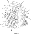
- These two electric cable bundles 75, 76 which are shown on FIG. figure 5 are also connected to the control board 33.
- the foot 74 makes it possible to place the lid 15 on a support to relieve the weight piping of the lid 15 and the injection units 12.
- each injection unit 12 is connected to an additive reservoir 9 via a first tube 77a connected to a first manifold 78 which is itself connected to the additive reservoir 9.
- the first manifold 78 can be connected two injection units 12 via two separate first tubes 77a.
- the additive injection device 8 is therefore capable of delivering the same additive in two respective fuel distribution lines 3 connected to two separate pistols 7 arranged on each side of the fuel dispenser 1.
- Each injection unit 12 is connected to a second manifold (not shown) via a second tube 77b.
- the second manifold is connected to the fuel distribution line 3.
- the figure 8 also shows electrical cables 79 emerging from the cable glands 63 of the explosion-proof housing 13. These electric cables 79 are connected to the computer located in the hydraulic compartment 2.
Landscapes
- Engineering & Computer Science (AREA)
- Mechanical Engineering (AREA)
- Fuel-Injection Apparatus (AREA)
Description
La présente invention a pour objet un distributeur de carburant dont le compartiment hydraulique est équipé d'un dispositif d'injection d'additif.The present invention relates to a fuel dispenser whose hydraulic compartment is equipped with an additive injection device.
D'une manière générale, les distributeurs de carburant que l'on rencontre dans les stations-service comprennent une unité de pompage destinée à aspirer le carburant dans une cuve de stockage comprenant une pompe entrainée par un moteur et une ligne de distribution reliée à cette unité de pompage. La ligne de distribution comprend un mesureur de débit de carburant mis en mouvement par l'unité de pompage et un tuyau flexible équipé d'un pistolet de distribution actionné par l'utilisateur pour remplir le réservoir de son véhicule.In general, fuel dispensers that are encountered at service stations include a pumping unit for sucking fuel into a storage tank comprising a pump driven by a motor and a distribution line connected thereto. pumping unit. The distribution line includes a fuel flow meter set in motion by the pumping unit and a flexible hose equipped with a user-operated dispensing gun for filling the tank of its vehicle.
Les compagnies pétrolières proposent de plus en plus aujourd'hui à leur clientèle des produits additifs en complément de leur carburant afin, par exemple, d'améliorer la lubrification des moteurs ou la combustion du carburant.Oil companies are increasingly offering additives products to their customers in addition to their fuel, for example to improve engine lubrication or fuel combustion.
Un des moyens actuellement connus pour ajouter un additif à un carburant consiste, soit à verser directement l'additif dans le réservoir du véhicule à partir, par exemple, d'un bidon vendu séparément, soit à réaliser l'adjonction plus en amont lors de la fabrication du carburant en raffinerie.One of the currently known means for adding an additive to a fuel is either to pour the additive directly into the tank of the vehicle from, for example, a can sold separately, or to carry out the addition further upstream when the manufacture of fuel in refineries.
Il existe également des dispositifs d'injection d'un additif liquide au cours de la distribution d'un carburant au travers d'une ligne de distribution d'un distributeur de carburant, comme décrit dans le document
Un tel dispositif d'injection comporte un réservoir d'additif liquide, une pompe d'aspiration de l'additif liquide, un moteur d'entraînement de la pompe d'aspiration et un conduit de circulation destiné à amener l'additif liquide jusqu'au pistolet de distribution. Le dispositif d'injection est apte à délivrer une dose d'additif dans la ligne de distribution de carburant qui est proportionnelle au débit de carburant traversant cette ligne.Such an injection device comprises a liquid additive reservoir, a suction pump for the liquid additive, a drive motor for the suction pump and a circulation duct intended to bring the liquid additive to at the dispensing gun. The injection device is adapted to deliver a dose of additive in the fuel distribution line which is proportional to the flow of fuel passing through this line.
Ainsi, le dispositif d'injection réalise une adjonction automatique d'additif dans la ligne de distribution et plus précisément en bout de ligne de distribution puisque l'adjonction est réalisée dans le pistolet. La précision quant à la concentration de l'additif liquide est parfaitement garantie quel que soit le débit de distribution de carburant imposé par l'utilisateur par son action sur le pistolet.Thus, the injection device performs an automatic addition of additive in the distribution line and more precisely at the end of the distribution line since the addition is carried out in the gun. The accuracy of the concentration of the liquid additive is perfectly guaranteed regardless of the fuel delivery rate imposed by the user by its action on the gun.
L'ensemble de pompage et le mesureur de débit de carburant des distributeurs de carburant sont classiquement logés dans un compartiment hydraulique. Le dispositif d'injection peut être placé dans le compartiment hydraulique, comme décrit dans le document
Le compartiment hydraulique est une zone dangereuse où l'on rencontre fréquemment des vapeurs de carburant. Pour éviter les risques d'explosion, tous les composants électriques présents dans le compartiment hydraulique doivent être conformes aux Directives Européennes 94/9/CE ou 2014/34/EU concernant les environnements explosibles, dites directives ATEX.The hydraulic compartment is a dangerous area where fuel vapors are frequently encountered. To avoid the risk of explosion, all electrical components in the hydraulic compartment must comply with the European Directives 94/9 / EC or 2014/34 / EU on Explosive Environments, known as ATEX directives.
Pour que le dispositif d'injection d'additif soit conforme aux normes et directives anti-explosion, il est connu d'utiliser une pompe d'aspiration entraînée par un moteur ATEX, permettant l'utilisation du système d'injection d'additif en toute sécurité dans un distributeur de carburant.In order for the additive injection device to comply with anti-explosion standards and directives, it is known to use a suction pump driven by an ATEX motor, allowing the use of the additive injection system in safely in a fuel dispenser.
Cependant, les moteurs ATEX présentent une enveloppe de protection supplémentaire qui les rend plus volumineux et plus chers que les moteurs classiques non ATEX. Le système d'injection peut comprendre plusieurs unités d'injection comprenant chacune une pompe et un moteur augmentant d'autant plus les coûts et l'encombrement.However, ATEX engines have an additional protective envelope that makes them larger and more expensive than conventional non-ATEX engines. The injection system may comprise a plurality of injection units each comprising a pump and a motor increasing all the more the costs and the bulk.
La présente invention a pour objet de remédier à cet inconvénient en proposant un distributeur de carburant dont le compartiment hydraulique est équipé d'un dispositif d'injection d'additif ATEX plus compact et moins cher.The present invention aims to overcome this disadvantage by providing a fuel dispenser whose hydraulic compartment is equipped with a more compact and cheaper ATEX additive injection device.
A cet effet, l'invention concerne un distributeur de carburant dont le compartiment hydraulique est équipé d'au moins un dispositif d'injection d'additif comprenant un réservoir d'additif et au moins une unité d'injection destinée à aspirer une quantité régulée d'additif depuis le réservoir d'additif jusqu'à une ligne de distribution de carburant du distributeur de carburant afin de délivrer un mélange carburant/additif. Cette unité d'injection comprend une pompe d'aspiration entraînée par un moteur. Le moteur est un moteur non ATEX.For this purpose, the invention relates to a fuel dispenser whose hydraulic compartment is equipped with at least one additive injection device comprising an additive reservoir and at least one injection unit for sucking up a regulated quantity. additive from the additive tank to a fuel distribution line of the fuel dispenser to deliver a fuel / additive mixture. This injection unit comprises a suction pump driven by a motor. The engine is a non-ATEX engine.
Selon l'invention, le dispositif d'injection d'additif comprend un boîtier antidéflagrant dans lequel est logé le moteur. La pompe d'aspiration est disposée à l'extérieur du boîtier antidéflagrant et est entrainée par le moteur par l'intermédiaire d'un axe d'entrainement traversant une paroi du boîtier antidéflagrant. La pompe d'aspiration et le moteur sont séparés par cette paroi du boîtier antidéflagrant.According to the invention, the additive injection device comprises an explosion-proof housing in which the engine is housed. The suction pump is disposed outside the explosion-proof housing and is driven by the motor via a drive shaft passing through a wall of the explosion-proof housing. The suction pump and the motor are separated by this wall of the explosion-proof housing.
Selon une autre caractéristique de l'invention, l'unité d'injection comprend une bride fixée sur la paroi du boîtier antidéflagrant et recouvrant une ouverture formée dans cette paroi. Le moteur est fixé sur une première face de la bride et la pompe d'aspiration est fixée sur une deuxième face de la bride opposée à la première face. L'axe d'entrainement traverse la bride pour relier le moteur à la pompe d'aspiration et un premier chemin de flamme est prévu entre la bride et la paroi.According to another characteristic of the invention, the injection unit comprises a flange fixed on the wall of the explosion-proof housing and covering an opening formed in this wall. The motor is fixed on a first face of the flange and the suction pump is fixed on a second face of the flange opposite to the first face. The drive shaft passes through the flange to connect the motor to the suction pump and a first flame path is provided between the flange and the wall.
Selon une autre caractéristique de l'invention, l'ouverture de la paroi du boîtier antidéflagrant est délimitée par une surface périphérique. La bride comprend une partie inférieure circulaire comportant une surface périphérique en regard de la surface périphérique de l'ouverture de la paroi du boîtier antidéflagrant et séparée de celle-ci par un espace formant une première partie du premier chemin de flamme.According to another characteristic of the invention, the opening of the wall of the explosion-proof housing is delimited by a peripheral surface. The flange comprises a circular lower portion having a peripheral surface facing the surface peripheral of the opening of the wall of the explosion-proof housing and separated therefrom by a space forming a first portion of the first flame path.
Selon une autre caractéristique de l'invention, l'espace formant la première partie du premier chemin de flamme est inférieur ou égal à 0,5 mm et est de préférence inférieur ou égal à 0,15 mm.According to another characteristic of the invention, the space forming the first part of the first flame path is less than or equal to 0.5 mm and is preferably less than or equal to 0.15 mm.
Selon une autre caractéristique de l'invention, la bride comprend une partie supérieure s'étendant radialement par rapport à la partie inférieure circulaire. La partie supérieure comporte une surface d'appui périphérique venant en contact sur une surface externe de la paroi du boîtier antidéflagrant. Une deuxième partie du premier chemin de flamme est formée entre ces surfaces.According to another characteristic of the invention, the flange comprises an upper portion extending radially relative to the circular lower part. The upper portion has a peripheral bearing surface contacting an outer surface of the wall of the explosion-proof housing. A second portion of the first flame path is formed between these surfaces.
Selon une autre caractéristique de l'invention, la bride comprend un canal central traversé par l'axe d'entrainement. Un deuxième espace est prévu entre l'axe d'entrainement et la bride de façon à former un second chemin de flamme.According to another characteristic of the invention, the flange comprises a central channel through which the drive shaft passes. A second gap is provided between the drive shaft and the flange to form a second flame path.
Selon une autre caractéristique de l'invention, le deuxième espace formant le deuxième chemin de flamme est inférieur ou égal à 0,5 mm et est de préférence inférieur ou égal à 0,2 mm.According to another characteristic of the invention, the second space forming the second flame path is less than or equal to 0.5 mm and is preferably less than or equal to 0.2 mm.
Selon une autre caractéristique de l'invention, la paroi du boîtier antidéflagrant est un couvercle amovible reposant sur une surface d'appui du boîtier antidéflagrant, formant un troisième chemin de flamme.According to another characteristic of the invention, the wall of the explosion-proof housing is a removable cover resting on a bearing surface of the explosion-proof housing, forming a third flame path.
Selon une autre caractéristique de l'invention, le moteur est fixé directement sur la bride de façon à être en contact avec celle-ci. Ce moteur entraine une première portion d'axe avant pour entrainer la pompe d'aspiration et une deuxième portion d'axe arrière coopérant avec un détecteur de position positionné à l'arrière du moteur.According to another characteristic of the invention, the motor is fixed directly on the flange so as to be in contact therewith. This motor drives a first portion of the front axle to drive the suction pump and a second portion of rear axle cooperating with a position sensor positioned at the rear of the engine.
Ainsi, l'invention fournit un distributeur de carburant dont le compartiment hydraulique est équipé d'un dispositif d'injection d'additif ATEX permettant son utilisation en atmosphère explosive, plus compact et moins cher que ceux de l'art antérieur.Thus, the invention provides a fuel dispenser whose hydraulic compartment is equipped with an ATEX additive injection device for its use in explosive atmosphere, more compact and cheaper than those of the prior art.
En effet, l'invention permet d'utiliser des moteurs non ATEX moins encombrants et moins chers que les moteurs ATEX.Indeed, the invention allows the use of non-ATEX engines less bulky and cheaper than ATEX engines.
Selon une autre caractéristique de l'invention, l'unité de pompage est connectée à deux lignes de distribution de carburant comportant chacune un mesureur de débit et un tuyau flexible équipé d'un pistolet, le dispositif d'injection d'additif comprenant deux unités d'injection connectées au réservoir d'additif et connectées chacune à une ligne de distribution de carburant respective, le dispositif d'injection d'additif comprenant une carte de contrôle pour commander les moteurs disposée dans le fond du boitier antidéflagrant.According to another characteristic of the invention, the pumping unit is connected to two fuel distribution lines each comprising a flow meter and a hose equipped with a gun, the additive injection device comprising two units. injectors connected to the additive reservoir and each connected to a respective fuel distribution line, the additive injection device comprising a control card for controlling the engines disposed in the bottom of the explosion-proof housing.
Cette configuration permet de rendre le dispositif d'injection d'additif plus compact et d'éviter d'avoir des câbles électriques supplémentaires traversant le boîtier antidéflagrant pour relier la carte qui serait dans ce cas à l'extérieur du boîtier antidéflagrant.This configuration makes it possible to make the additive injection device more compact and to avoid having additional electrical cables passing through the explosion-proof housing in order to connect the card which would in this case be outside the explosion-proof housing.
Selon une autre caractéristique de l'invention, le boîtier antidéflagrant est placé sous le réservoir d'additif, de façon à former un empilement vertical, le réservoir d'additif comprenant une sortie à sa partie inférieure reliée à l'unité d'injection.According to another characteristic of the invention, the explosion-proof housing is placed under the additive reservoir, so as to form a vertical stack, the additive reservoir comprising an outlet at its lower part connected to the injection unit.
Cette configuration permet d'obtenir un empilement vertical le moins encombrant possible. De plus, elle permet d'obtenir un écoulement de l'additif simplement par gravité, évitant les bulles d'air dans l'additif et l'utilisation d'un système de dégazage. Cet agencement permet également de réduire au maximum la longueur des canalisations entre le réservoir et l'unité d'injection, réduisant les coûts.This configuration provides a vertical stack the least bulky possible. In addition, it makes it possible to obtain a flow of the additive simply by gravity, avoiding air bubbles in the additive and the use of a degassing system. This arrangement also minimizes the length of the pipes between the tank and the injection unit, reducing costs.
Le dispositif d'injection d'additif est placé à l'extrémité du compartiment hydraulique, dans un premier logement délimité par une première paroi latérale et par une deuxième paroi latérale prolongée à sa partie inférieure par un support de réservoir perpendiculaire au reste de la deuxième paroi latérale. Le boîtier antidéflagrant est fixé au support de réservoir au moyen d'un élément de fixation.The additive injection device is placed at the end of the hydraulic compartment, in a first housing delimited by a first side wall and a second side wall extended at its lower part by a reservoir support perpendicular to the rest of the second side wall. The flameproof housing is attached to the tank support by means of a fastener.
Ceci permet d'obtenir un dispositif d'injection d'additif très compact, insérable dans un logement initialement prévu pour une unité de pompage de carburant. Autrement dit, le dispositif d'injection prend la place d'une unité de pompage de carburant, permettant de ne pas modifier le châssis des distributeurs de carburant, ni de rallonger le distributeur de carburant. Un distributeur de carburant déjà en service dans une station peut ainsi être modifié et intégrer un dispositif d'injection d'additif.This provides a very compact additive injection device, insertable into a housing initially provided for a fuel pumping unit. In other words, the injection device takes the place of a fuel pump unit, not to change the chassis of the fuel dispensers, or to extend the fuel dispenser. A fuel dispenser already in service in a station can thus be modified and integrate an additive injection device.
Les caractéristiques du distributeur de carburant qui fait l'objet de l'invention seront décrites plus en détail en se référant aux dessins non limitatifs annexés dans lesquels :
- la
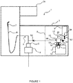
figure 1 représente schématiquement un distributeur de carburant comprenant un dispositif d'injection d'additif selon l'invention, - la
figure 2 est une vue en coupe schématique d'une unité d'injection montée sur une paroi du boitier antidéflagrant, - les
figures 3 et 4 représentent en perspective et respectivement une vue de dessous et une vue de dessus de la bride, - la
figure 5 est une vue en perspective schématique d'une unité d'injection selon un mode de réalisation possible, - la
figure 6 représente schématiquement le boîtier antidéflagrant d'un dispositif d'injection d'additif sur le couvercle duquel sont fixées quatre unités d'injection, - la
figure 7 est une vue éclatée du boîtier antidéflagrant représenté sur lafigure 6 , - la
figure 8 représente schématiquement le dispositif d'injection d'additif tel qu'il est monté dans un compartiment hydraulique.
- the
figure 1 schematically represents a fuel dispenser comprising an additive injection device according to the invention, - the
figure 2 is a schematic sectional view of an injection unit mounted on a wall of the explosion-proof housing, - the
Figures 3 and 4 represent in perspective and respectively a bottom view and a top view of the flange, - the
figure 5 is a schematic perspective view of an injection unit according to a possible embodiment, - the
figure 6 schematically represents the explosion-proof housing of an additive injection device on the lid of which are fixed four injection units, - the
figure 7 is an exploded view of the explosion-proof housing shown on thefigure 6 , - the
figure 8 schematically represents the additive injection device as it is mounted in a hydraulic compartment.
Comme représenté sur la
Plus fréquemment, l'unité de pompage 4 comporte deux lignes de distribution de carburant 3 chacune associée à l'un des côtés du distributeur de carburant 1.More frequently, the pumping unit 4 comprises two
Le distributeur de carburant 1 comprend un dispositif d'injection d'additif 8 qui est disposé à l'intérieur du compartiment hydraulique 2.The fuel dispenser 1 comprises an
Le dispositif d'injection d'additif 8 comprend au moins un réservoir d'additif 9 et au moins une unité d'injection 12 destinée à aspirer une quantité régulée d'additif depuis le réservoir d'additif 9 jusqu'à la ligne de distribution de carburant 3 du distributeur de carburant 1.The
L'unité d'injection 12 comprend une pompe d'aspiration 10 entraînée par un moteur 11.The
Le dispositif d'injection d'additif 8 comprend un boîtier antidéflagrant 13 dans lequel est logé le moteur 11. La pompe d'aspiration 10 est disposée à l'extérieur du boîtier antidéflagrant 13 et est entrainée par le moteur 11 par l'intermédiaire d'un axe d'entrainement 14 traversant une paroi 15 du boîtier antidéflagrant 13. La pompe d'aspiration 10 et le moteur 11 sont séparés par la paroi 15 du boîtier antidéflagrant 13.The
A titre d'exemple, le boîtier antidéflagrant 13 peut être une boîte de jonction Exd ou Exe de type M2000.By way of example, the explosion-
Comme représenté sur les
Comme représenté sur la
La paroi 15 du boîtier antidéflagrant 13 comprend une ouverture 20 dans laquelle est logée la bride 16. L'ouverture 20 de la paroi 15 du boîtier antidéflagrant 13 est délimitée par une surface périphérique 23 de section circulaire. Comme représenté sur les
L'espace 37 formant la première partie 19a du premier chemin de flamme 19a, 19b est inférieur ou égal à 0,5 mm et de préférence inférieur ou égal à 0,15 mm, de façon à permettre à une flamme d'être laminée et d'arrêter la propagation de celle-ci en cas d'explosion dans le boîtier antidéflagrant 13. L'espace 37 est avantageusement de 0,15 mm.The space 37 forming the
La première partie 19a du premier chemin de flamme 19a, 19b présente un volume de section annulaire, c'est-à-dire un volume défini entre deux tubes concentriques. Le volume de section annulaire est avantageusement constant tout autour de la partie inférieure circulaire 24 de la bride 16. Le premier chemin de flamme 19a, 19b permet une communication fluidique entre l'intérieur du boîtier antidéflagrant 13 et l'extérieur, de façon à laminer la flamme.The
La bride 16 comprend une partie supérieure 26 s'étendant radialement par rapport à la partie inférieure circulaire 24. La partie supérieure 26 comporte une surface d'appui périphérique 28 venant en contact sur une surface externe 27 de la paroi 15 du boîtier antidéflagrant 13.The
Une deuxième partie 19b du premier chemin de flamme 19a, 19b est formée entre la surface d'appui périphérique 28 de la partie inférieure circulaire 24 de la bride 16 et la surface externe 27 de la paroi 15 du boîtier antidéflagrant 13. Ces surfaces 27, 28 ont des petits défauts de planéité. Le contact entre ces surfaces 27, 28 n'est pas parfait, ce qui suffit à laminer une éventuelle flamme.A
La surface périphérique 25 de la partie inférieure circulaire 24 et la surface d'appui périphérique 28 de la partie supérieure 26 de la bride 16 forment une surface continue. Dans cet exemple, ces surfaces 25, 28 sont perpendiculaires.The
En d'autres termes, la première partie 19a du premier chemin de flamme 19a, 19b est prolongée par la deuxième partie 19b du premier chemin de flamme 19a, 19b pour permettre au premier chemin de flamme 19a, 19b de déboucher à l'extérieur du boîtier antidéflagrant 13.In other words, the
La bride 16 comprend un canal central 21 traversé par l'axe d'entrainement 14. Un espace 22 ou jeu est prévu entre l'axe d'entrainement 14 et la bride 16 de façon à former un second chemin de flamme 22a.The
Le second chemin de flamme 22a entoure complètement l'axe d'entrainement 14. Le second chemin de flamme 22a présente un volume de section annulaire. Le second chemin de flamme 22a permet une communication fluidique entre l'intérieur du boîtier antidéflagrant 13 et l'extérieur, de façon à évacuer la pression lors d'une explosion à l'intérieur du boîtier antidéflagrant 13 tout en arrêtant la propagation de la flamme.The second flame path 22a completely surrounds the
Le deuxième espace 22 formant le deuxième chemin de flamme 22a est inférieur ou égal à 0,5 mm et de préférence inférieur ou égal à 0,2 mm.The second space 22 forming the second flame path 22a is less than or equal to 0.5 mm and preferably less than or equal to 0.2 mm.
Dans l'exemple de la
La
En d'autres termes, le canal central 21 de forme tubulaire de la bride 16 est prolongé par l'espace plus grand 55 de forme tronconique. D'autres formes sont possibles.In other words, the
Comme représenté sur les
La pompe d'aspiration 10 est fixée à la bride 16 par l'intermédiaire d'un support 39, comme représenté sur la
Comme représenté sur les
La pompe d'aspiration 10 est fixée au support 39 par deux vis 42 de chaque côté du support 39.The
Selon les
Le piston rotatif 43 de la pompe d'aspiration 10 est relié à la première portion d'axe avant 31 du moteur par l'intermédiaire d'une rotule 45. Le moteur 11 est relié à la première portion d'axe avant 31 pour entrainer la pompe d'aspiration 10. Le piston rotatif 43 effectue à la fois un mouvement de rotation et un mouvement de translation pour délivrer une dose d'additif.The
Ce type de pompe d'aspiration 10 est connu. Il est possible d'utiliser une pompe à piston telle celle que commercialisée par la société Fluid Metering Inc. Cette pompe à piston comprend un piston en céramique ainsi qu'une chemise en céramique qui sont inertes chimiquement aux additifs injectés dans le carburant.This type of
Selon le mode de réalisation des
Comme représenté sur la
Le détecteur de position 36 est disposé à l'arrière du moteur 11 et comprend un disque 44 muni d'une fente solidaire de la deuxième portion d'axe arrière 32 du moteur 11. Un ensemble émetteur/récepteur 51 est fixé à l'arrière du moteur 11 pour détecter la position de la fente. L'arrière du moteur 11 est recouvert par un couvercle 52 pour protéger le détecteur de position 36 et la deuxième portion d'axe arrière 32 du moteur 11.The
L'axe d'entrainement 14 du moteur 11 est centré et guidé par deux roulements 53, 54.The
Comme représenté sur la
Comme représenté sur la
Selon un autre mode de réalisation possible (non représenté), un support intermédiaire est prévu entre le moteur et la bride qui n'est pas en contact direct avec le moteur dans ce cas. Le moteur est alors fixé sur la bride intermédiaire qui est elle-même fixée sur la bride. Le détecteur de position est disposé entre le moteur et la bride.According to another possible embodiment (not shown), an intermediate support is provided between the motor and the flange which is not in direct contact with the motor in this case. The motor is then fixed on the intermediate flange which is itself fixed on the flange. The position detector is disposed between the motor and the flange.
Le boîtier antidéflagrant 13 est un boitier métallique, de préférence en aluminium.The explosion-
Comme représenté sur la
Le couvercle 15 est fixé au boîtier antidéflagrant 13 par dix vis 60, par exemple, s'insérant dans les orifices 61 du couvercle 15 et se vissant dans des orifices filetés 62 prévus dans le boîtier antidéflagrant 13.The
Comme représenté sur la
Alternativement, la paroi 15 sur laquelle sont fixées les unités d'injection 12 pourrait être une des parois latérales ou arrière du boîtier antidéflagrant 13, non représentée.Alternatively, the
A titre d'exemple, le boîtier antidéflagrant 13 présente une longueur de 22 cm, une largeur de 14 cm et une profondeur de 11,7 cm environ.For example, the explosion-
Dans cet exemple, la pompe d'aspiration 10 est une pompe à piston rotatif telle que décrite précédemment délivrant une dose de 0,1 ml d'additif par révolution. La pompe délivre une dose calibrée d'additif de façon précise, ce qui permet de s'affranchir d'un mesureur de débit. La pompe d'aspiration 10 est une pompe ATEX, respectant la Directive Européenne 94/9/CE ou 2014/34/EU concernant les environnements explosifs. Par conséquent, elle peut être disposée dans le compartiment hydraulique 2 et à l'extérieur du boitier antidéflagrant 13, c'est-à-dire dans une zone où des vapeurs de carburant sont susceptibles de se former.In this example, the
D'autres types de pompe peuvent également être utilisés comme des pompes volumétriques.Other types of pumps can also be used as positive displacement pumps.
Comme représenté sur les
Le moteur 11 est un moteur pas à pas contrôlé par une carte de contrôle 33 représentée sur la
Selon la
La concentration de l'additif dans le carburant est prédéfinie avant la transaction en carburant.The concentration of the additive in the fuel is predefined before the fuel transaction.
Le mesureur de débit 5 qui est de préférence un mesureur volumétrique, mesure le volume de carburant délivré. Il transmet un signal de mesure à un calculateur logé dans le compartiment hydraulique 2 qui calcule en temps réel le volume d'additif à injecter en fonction du volume du carburant délivré. Un signal de commande est ensuite transmis du calculateur vers la carte de contrôle 33 du dispositif d'injection d'additif 8. Cela se traduit par un nombre de tours à effectuer par le moteur 11 de l'unité d'injection 12. Le moteur 11 reçoit donc un signal de commande par la carte de contrôle 33 pour commander le nombre de tours à effectuer. Le volume d'additif est ainsi proportionnel au volume de carburant.The
Comme représenté sur les
Une vanne 69 anti-retour (
Le dispositif d'injection d'additif 8 peut comprendre plusieurs unités d'injection 12, chacune associée à une ligne de distribution de carburant 3 respective et donc à un pistolet 7 respectif.The
Selon l'exemple de réalisation représenté sur les
Comme représenté sur la
Ce premier logement 80 est adjacent à celui d'un deuxième logement 81 prévu pour recevoir une unité de pompage 4 de carburant. Ce premier logement 80 est délimité par une première paroi latérale 70a et par une deuxième paroi latérale 70b. Cette première paroi latérale 70a comprend un orifice 71 pour permettre l'accès aux unités d'injection 12 lors d'une opération de maintenance.This
Cette première paroi latérale 70a est celle qui se situe à l'extrémité du compartiment hydraulique 2 qui est la plus éloignée du compartiment électronique 2a (
Selon l'exemple de réalisation représenté sur la
La sortie du réservoir d'additif 64 (
La deuxième paroi latérale 70b présente une forme de « L ». Elle est prolongée à sa partie inférieure par un support de réservoir perpendiculaire au reste de la deuxième paroi latérale 70b (non représenté). Les réservoirs d'additif 9 sont posés sur le support de réservoir. Le boîtier antidéflagrant 13 est fixé à ce support de réservoir au moyen d'un élément de fixation 72 ayant une forme générale de « L », comme représenté sur la
Le couvercle 15 du boîtier antidéflagrant 13 comprend un pied 74 fixé sur la partie inférieure du couvercle 15 pour faciliter la maintenance. En effet, chaque unité d'injection 12 comprend un premier faisceau de câbles électriques 75 connecté au détecteur de position 36 et un deuxième faisceau de câbles électriques 76 relié au moteur 11. Ces deux faisceaux de câbles électriques 75, 76 qui sont représentés sur la
Comme représenté sur la
Les éléments reliant le réservoir d'additif, situé à gauche de la
Chaque unité d'injection 12 est reliée à un deuxième collecteur (non représenté) via un deuxième tube 77b. Le deuxième collecteur est relié à la ligne de distribution de carburant 3.Each
La
Claims (11)
- Fuel distributor (1) comprising a hydraulic compartment (2) comprising, on the one hand, at least one pumping unit (4) connected to at least one fuel distribution line (3) comprising a meter (5) for measuring the fuel flow rate and a flexible hose (6) equipped with a nozzle (7) and, on the other hand, at least one additive injection device (8) comprising an additive tank (9) and at least one injection unit (12) intended to draw up a regulated quantity of additive from the additive tank (9) as far as the fuel distribution line (3), this injection unit (12) comprising a lift pump (10) driven by a motor (11),
characterized in that
the additive injection device (8) comprises a flameproof casing (13) in which the motor (11) is housed, the lift pump (10) being mounted on the outside of the flameproof casing (13) and being driven by the motor (11) via a drive shaft (14) that passes through a wall (15) of the flameproof casing (13), the lift pump (10) and the motor (11) being separated by this wall (15) of the flameproof casing. - Fuel distributor (1) according to Claim 1, characterized in that the injection unit (12) comprises a flange (16) fixed to the wall (15) of the flameproof casing (13) and covering an opening (20) formed in this wall (15), the motor (11) being fixed to a first face (17) of the flange (16) and the lift pump (10) being fixed to a second face (18) of the flange (16) which is the opposite face to the first face (17), the drive shaft (14) passing through the flange (16) to connect the motor (11) to the lift pump (10), a first flame path (19a, 19b) being provided between the flange (16) and the wall (15).
- Fuel distributor (1) according to Claim 2,
characterized in that
the opening (20) in the wall (15) of the flameproof casing (13) is delimited by a peripheral surface (23), the flange (16) comprising a circular lower part (24) comprising a peripheral surface (25) facing the peripheral surface (23) of the opening (20) in the wall (15) of the flameproof casing (13) and separated therefrom by a space (37) forming the first part (19a) of the first flame path (19a, 19b). - Fuel distributor (1) according to Claim 3,
characterized in that
the space (37) that forms the first part (19a) of the first flame path is less than or equal to 0.5 mm and preferably less than or equal to 0.15 mm. - Fuel distributor (1) according to any one of Claims 2 to 4,
characterized in that
the flange (16) comprises an upper part (26) extending radially with respect to the circular lower part (24), the upper part (26) comprising a peripheral bearing surface (28) coming into contact with an external surface (27) of the wall (15) of the flameproof casing (13), a second part (19b) of the first flame path (19a, 19b) being formed between these surfaces. - Fuel distributor (1) according to any one of Claims 2 to 5,
characterized in that
the flange (16) comprises a central passage (21) through which the drive shaft (14) passes, a second space (22) being provided between the drive shaft (14) and the flange (16) so as to form a second flame path (22a). - Fuel distributor (1) according to Claim 6,
characterized in that
the second space (22) that forms the second flame path (22a) is less than or equal to 0.5 mm and preferably less than or equal to 0.2 mm. - Fuel distributor (1) according to either one of Claims 6 and 7,
characterized in that
the wall (15) of the flameproof casing (13) is a removable cover resting on a bearing surface (29) of this flameproof casing (13), forming a third flame path (30). - Fuel distributor (1) according to any one of Claims 2 to 8,
characterized in that
the motor (11) is fixed directly to the flange (16) so as to be in contact therewith, this motor (11) driving a front first portion of shaft (31) to drive the lift pump (10) and a rear second portion of shaft (32) collaborating with a position detector (36) positioned at the rear of the motor (11). - Fuel distributor (1) according to one of Claims 1 to 9,
characterized in that
the pump unit (4) is connected to two fuel distribution lines (3) each comprising a meter (5) for measuring the flow rate and a flexible hose (6) equipped with a nozzle (7), the additive injection device (8) comprising two injection units (12) connected to the additive tank (9) and each connected to one respective fuel distribution line (3), the additive injection device (8) comprising a control board (33) for controlling the motors (11) and positioned in the bottom (34) of the flameproof casing (13). - Fuel distributor (1) according to any one of Claims 1 to 10,
characterized in that
the flameproof casing (13) is positioned under the additive tank (9) so as to form a vertical stack, the additive tank (9) comprising an outlet (64) in its lower part which is connected to the injection unit (12) and the said additive injection device (8) being positioned at the end of the hydraulic compartment (2) in a first housing (80) delimited by a first lateral wall (70a) and by a second lateral wall (70b) extended in its lower part by a tank support perpendicular to the rest of the second lateral wall (70b), the flameproof casing (13) being fixed to the tank support by means of a fixing element (72).
Applications Claiming Priority (2)
| Application Number | Priority Date | Filing Date | Title |
|---|---|---|---|
| FR1560130A FR3042787A1 (en) | 2015-10-23 | 2015-10-23 | FUEL DISPENSER HAVING HYDRAULIC COMPARTMENT EQUIPPED WITH ADDITIVE INJECTION DEVICE |
| PCT/IB2016/056350 WO2017068545A1 (en) | 2015-10-23 | 2016-10-21 | Fuel distributor, the hydraulic compartment of which is equipped with an additive injection device |
Publications (2)
| Publication Number | Publication Date |
|---|---|
| EP3365268A1 EP3365268A1 (en) | 2018-08-29 |
| EP3365268B1 true EP3365268B1 (en) | 2019-10-16 |
Family
ID=54848796
Family Applications (1)
| Application Number | Title | Priority Date | Filing Date |
|---|---|---|---|
| EP16790717.9A Active EP3365268B1 (en) | 2015-10-23 | 2016-10-21 | Fuel distributor, the hydraulic compartment of which is equipped with an additive injection device |
Country Status (6)
| Country | Link |
|---|---|
| EP (1) | EP3365268B1 (en) |
| CN (1) | CN108367906B (en) |
| AU (1) | AU2016340366C1 (en) |
| FR (1) | FR3042787A1 (en) |
| PT (1) | PT3365268T (en) |
| WO (1) | WO2017068545A1 (en) |
Families Citing this family (2)
| Publication number | Priority date | Publication date | Assignee | Title |
|---|---|---|---|---|
| SE543664C2 (en) * | 2019-06-05 | 2021-05-25 | Wayne Fueling Systems Sweden Ab | A fuel dispensing unit and a method for handling additives inside a fuel dispensing unit |
| US11939209B2 (en) | 2020-06-11 | 2024-03-26 | Wayne Fueling Systems Llc | Metering pumps for fueling applications |
Family Cites Families (8)
| Publication number | Priority date | Publication date | Assignee | Title |
|---|---|---|---|---|
| DE29502004U1 (en) * | 1995-02-08 | 1996-06-05 | Hanning & Kahl GmbH & Co., 33813 Oerlinghausen | Explosion-proof electrical machine |
| FR2756268B1 (en) * | 1996-11-28 | 1998-12-18 | Schlumberger Ind Sa | DEVICE FOR INJECTING LIQUID ADDITIVE INTO FUEL |
| US6392322B1 (en) * | 2000-01-31 | 2002-05-21 | Precision Engine Controls Corporation | Rugged explosion-proof actuator with integral electronics |
| DE10317181B4 (en) * | 2003-04-15 | 2006-05-24 | Alexander Schischek | Drive, especially actuator and control drive, for flaps and valves |
| CN202190168U (en) * | 2011-08-03 | 2012-04-11 | 中煤科工集团重庆研究院 | Mining DC brushless micropump |
| CN202529835U (en) * | 2012-02-23 | 2012-11-14 | 北京全盛虎安防爆科技有限责任公司 | Moveable separating anti-explosion type fuel storing and filling device |
| CN104512857A (en) * | 2013-09-29 | 2015-04-15 | 德莱赛稳加油设备(上海)有限公司 | Additive injection device and method for fuel filling machine |
| CN203683071U (en) * | 2013-12-20 | 2014-07-02 | 航天晨光股份有限公司 | Device for charging oilseed additives in on-line mode |
-
2015
- 2015-10-23 FR FR1560130A patent/FR3042787A1/en active Pending
-
2016
- 2016-10-21 PT PT167907179T patent/PT3365268T/en unknown
- 2016-10-21 AU AU2016340366A patent/AU2016340366C1/en active Active
- 2016-10-21 CN CN201680068581.XA patent/CN108367906B/en active Active
- 2016-10-21 EP EP16790717.9A patent/EP3365268B1/en active Active
- 2016-10-21 WO PCT/IB2016/056350 patent/WO2017068545A1/en active Application Filing
Non-Patent Citations (1)
| Title |
|---|
| None * |
Also Published As
| Publication number | Publication date |
|---|---|
| CN108367906A (en) | 2018-08-03 |
| PT3365268T (en) | 2019-12-16 |
| EP3365268A1 (en) | 2018-08-29 |
| FR3042787A1 (en) | 2017-04-28 |
| AU2016340366B2 (en) | 2018-11-08 |
| AU2016340366A1 (en) | 2018-05-24 |
| CN108367906B (en) | 2020-05-26 |
| WO2017068545A1 (en) | 2017-04-27 |
| AU2016340366C1 (en) | 2019-04-11 |
Similar Documents
| Publication | Publication Date | Title |
|---|---|---|
| EP3365268B1 (en) | Fuel distributor, the hydraulic compartment of which is equipped with an additive injection device | |
| FR2658864A1 (en) | LUBRICATING AND / OR COOLING OIL SUPPLY SYSTEM FOR A MACHINE, ESPECIALLY FOR AN INTERNAL COMBUSTION ENGINE. | |
| FR2657598A1 (en) | DEVICE FOR DISPENSING AND MIXING FLUIDS FOR AUTOMOBILE. | |
| EP0903255B1 (en) | Pumping device and motor vehicle fuel tank with such a device | |
| FR2834006A1 (en) | Motor vehicle fuel feed system comprises tank with additive reservoir inside one of its linked receiving chambers with well modules | |
| EP2354002B1 (en) | Method and device for emptying a tank, tank and aircraft provided with such a device | |
| EP2396272A1 (en) | Apparatus for pouring a liquid into a glass, in particular wine | |
| EP1135589B1 (en) | Liquid transferring assembly, in particular for fuel additive | |
| FR2834004A1 (en) | Motor vehicle fuel additive feed system has dosing pump integrated in fuel well module inside main fuel tank | |
| EP2396248B1 (en) | Dispensing device for a cosmetical liquid product | |
| FR2807021A1 (en) | Integrated fuel pump/counter unit, for automobile filling station, uses rotation sensor for one of two motor driven rotors | |
| FR2539355A1 (en) | TANK FOR STORING THE FUEL SUPPLY OF AN INTERNAL COMBUSTION ENGINE USING LIQUID FUEL AND GAS FUEL, ESPECIALLY LIQUEFIED | |
| FR2918944A1 (en) | Brake fluid storing device for engine compartment of motor vehicle, has unit mounted movably in rotation/translation between filling position for connecting tank to tool and rest position in which unit does not obstruct compartment | |
| WO1998023530A1 (en) | Device for injecting liquid additive into a fuel | |
| EP2177474B1 (en) | Dispenser housing for LPG dispenser | |
| EP2362193A1 (en) | Gauging device for liquid fuel dispenser and method implemented by using this device | |
| EP2042704A1 (en) | Degassing unit equipped with a plunger tube and a settling chamber | |
| FR2805002A1 (en) | Motor vehicle i.c. engine fuel feed circuit liquid additive injector has supple pouch inside fixed container linked to feed line by needle | |
| FR2830283A1 (en) | Motor vehicle fluid tank has pump is sealed chamber inside tank, connected to interior of tank by suction pipe | |
| FR3099467A1 (en) | Food liquid container and food liquid dispensing apparatus using the container | |
| EP0018277B1 (en) | Device permitting the registration of volumes of liquid put back in a reservoir after flow control | |
| FR2466372A3 (en) | Extractor for emptying engine sumps - has waste oil reservoir which pneumatic pump fills or empties via flexible pipe | |
| FR3147240A1 (en) | Bearing comprising an oil conveying means. | |
| FR2794737A1 (en) | Motor vehicle refuelling pump vapour recuperation system has flow of positive displacement vacuum pump distributed through manifold to return lines | |
| FR3051152A1 (en) | COMPACT GAUGE-PUMP MODULE FOR LIQUID TANK |
Legal Events
| Date | Code | Title | Description |
|---|---|---|---|
| STAA | Information on the status of an ep patent application or granted ep patent |
Free format text: STATUS: UNKNOWN |
|
| STAA | Information on the status of an ep patent application or granted ep patent |
Free format text: STATUS: THE INTERNATIONAL PUBLICATION HAS BEEN MADE |
|
| PUAI | Public reference made under article 153(3) epc to a published international application that has entered the european phase |
Free format text: ORIGINAL CODE: 0009012 |
|
| STAA | Information on the status of an ep patent application or granted ep patent |
Free format text: STATUS: REQUEST FOR EXAMINATION WAS MADE |
|
| 17P | Request for examination filed |
Effective date: 20180523 |
|
| AK | Designated contracting states |
Kind code of ref document: A1 Designated state(s): AL AT BE BG CH CY CZ DE DK EE ES FI FR GB GR HR HU IE IS IT LI LT LU LV MC MK MT NL NO PL PT RO RS SE SI SK SM TR |
|
| AX | Request for extension of the european patent |
Extension state: BA ME |
|
| DAV | Request for validation of the european patent (deleted) | ||
| DAX | Request for extension of the european patent (deleted) | ||
| GRAP | Despatch of communication of intention to grant a patent |
Free format text: ORIGINAL CODE: EPIDOSNIGR1 |
|
| STAA | Information on the status of an ep patent application or granted ep patent |
Free format text: STATUS: GRANT OF PATENT IS INTENDED |
|
| INTG | Intention to grant announced |
Effective date: 20190429 |
|
| GRAJ | Information related to disapproval of communication of intention to grant by the applicant or resumption of examination proceedings by the epo deleted |
Free format text: ORIGINAL CODE: EPIDOSDIGR1 |
|
| STAA | Information on the status of an ep patent application or granted ep patent |
Free format text: STATUS: REQUEST FOR EXAMINATION WAS MADE |
|
| GRAR | Information related to intention to grant a patent recorded |
Free format text: ORIGINAL CODE: EPIDOSNIGR71 |
|
| GRAS | Grant fee paid |
Free format text: ORIGINAL CODE: EPIDOSNIGR3 |
|
| STAA | Information on the status of an ep patent application or granted ep patent |
Free format text: STATUS: GRANT OF PATENT IS INTENDED |
|
| GRAA | (expected) grant |
Free format text: ORIGINAL CODE: 0009210 |
|
| STAA | Information on the status of an ep patent application or granted ep patent |
Free format text: STATUS: THE PATENT HAS BEEN GRANTED |
|
| INTC | Intention to grant announced (deleted) | ||
| INTG | Intention to grant announced |
Effective date: 20190905 |
|
| AK | Designated contracting states |
Kind code of ref document: B1 Designated state(s): AL AT BE BG CH CY CZ DE DK EE ES FI FR GB GR HR HU IE IS IT LI LT LU LV MC MK MT NL NO PL PT RO RS SE SI SK SM TR |
|
| REG | Reference to a national code |
Ref country code: GB Ref legal event code: FG4D Free format text: NOT ENGLISH |
|
| REG | Reference to a national code |
Ref country code: CH Ref legal event code: EP |
|
| REG | Reference to a national code |
Ref country code: DE Ref legal event code: R096 Ref document number: 602016022638 Country of ref document: DE |
|
| REG | Reference to a national code |
Ref country code: IE Ref legal event code: FG4D Free format text: LANGUAGE OF EP DOCUMENT: FRENCH |
|
| REG | Reference to a national code |
Ref country code: AT Ref legal event code: REF Ref document number: 1191080 Country of ref document: AT Kind code of ref document: T Effective date: 20191115 |
|
| REG | Reference to a national code |
Ref country code: PT Ref legal event code: SC4A Ref document number: 3365268 Country of ref document: PT Date of ref document: 20191216 Kind code of ref document: T Free format text: AVAILABILITY OF NATIONAL TRANSLATION Effective date: 20191206 |
|
| REG | Reference to a national code |
Ref country code: NL Ref legal event code: MP Effective date: 20191016 |
|
| REG | Reference to a national code |
Ref country code: LT Ref legal event code: MG4D |
|
| REG | Reference to a national code |
Ref country code: AT Ref legal event code: MK05 Ref document number: 1191080 Country of ref document: AT Kind code of ref document: T Effective date: 20191016 |
|
| PG25 | Lapsed in a contracting state [announced via postgrant information from national office to epo] |
Ref country code: AT Free format text: LAPSE BECAUSE OF FAILURE TO SUBMIT A TRANSLATION OF THE DESCRIPTION OR TO PAY THE FEE WITHIN THE PRESCRIBED TIME-LIMIT Effective date: 20191016 Ref country code: GR Free format text: LAPSE BECAUSE OF FAILURE TO SUBMIT A TRANSLATION OF THE DESCRIPTION OR TO PAY THE FEE WITHIN THE PRESCRIBED TIME-LIMIT Effective date: 20200117 Ref country code: LT Free format text: LAPSE BECAUSE OF FAILURE TO SUBMIT A TRANSLATION OF THE DESCRIPTION OR TO PAY THE FEE WITHIN THE PRESCRIBED TIME-LIMIT Effective date: 20191016 Ref country code: BG Free format text: LAPSE BECAUSE OF FAILURE TO SUBMIT A TRANSLATION OF THE DESCRIPTION OR TO PAY THE FEE WITHIN THE PRESCRIBED TIME-LIMIT Effective date: 20200116 Ref country code: FI Free format text: LAPSE BECAUSE OF FAILURE TO SUBMIT A TRANSLATION OF THE DESCRIPTION OR TO PAY THE FEE WITHIN THE PRESCRIBED TIME-LIMIT Effective date: 20191016 Ref country code: NL Free format text: LAPSE BECAUSE OF FAILURE TO SUBMIT A TRANSLATION OF THE DESCRIPTION OR TO PAY THE FEE WITHIN THE PRESCRIBED TIME-LIMIT Effective date: 20191016 Ref country code: SE Free format text: LAPSE BECAUSE OF FAILURE TO SUBMIT A TRANSLATION OF THE DESCRIPTION OR TO PAY THE FEE WITHIN THE PRESCRIBED TIME-LIMIT Effective date: 20191016 Ref country code: LV Free format text: LAPSE BECAUSE OF FAILURE TO SUBMIT A TRANSLATION OF THE DESCRIPTION OR TO PAY THE FEE WITHIN THE PRESCRIBED TIME-LIMIT Effective date: 20191016 Ref country code: NO Free format text: LAPSE BECAUSE OF FAILURE TO SUBMIT A TRANSLATION OF THE DESCRIPTION OR TO PAY THE FEE WITHIN THE PRESCRIBED TIME-LIMIT Effective date: 20200116 Ref country code: PL Free format text: LAPSE BECAUSE OF FAILURE TO SUBMIT A TRANSLATION OF THE DESCRIPTION OR TO PAY THE FEE WITHIN THE PRESCRIBED TIME-LIMIT Effective date: 20191016 |
|
| PG25 | Lapsed in a contracting state [announced via postgrant information from national office to epo] |
Ref country code: RS Free format text: LAPSE BECAUSE OF FAILURE TO SUBMIT A TRANSLATION OF THE DESCRIPTION OR TO PAY THE FEE WITHIN THE PRESCRIBED TIME-LIMIT Effective date: 20191016 Ref country code: HR Free format text: LAPSE BECAUSE OF FAILURE TO SUBMIT A TRANSLATION OF THE DESCRIPTION OR TO PAY THE FEE WITHIN THE PRESCRIBED TIME-LIMIT Effective date: 20191016 Ref country code: IS Free format text: LAPSE BECAUSE OF FAILURE TO SUBMIT A TRANSLATION OF THE DESCRIPTION OR TO PAY THE FEE WITHIN THE PRESCRIBED TIME-LIMIT Effective date: 20200224 |
|
| REG | Reference to a national code |
Ref country code: CH Ref legal event code: PL |
|
| PG25 | Lapsed in a contracting state [announced via postgrant information from national office to epo] |
Ref country code: AL Free format text: LAPSE BECAUSE OF FAILURE TO SUBMIT A TRANSLATION OF THE DESCRIPTION OR TO PAY THE FEE WITHIN THE PRESCRIBED TIME-LIMIT Effective date: 20191016 |
|
| REG | Reference to a national code |
Ref country code: DE Ref legal event code: R097 Ref document number: 602016022638 Country of ref document: DE |
|
| PG2D | Information on lapse in contracting state deleted |
Ref country code: IS |
|
| PG25 | Lapsed in a contracting state [announced via postgrant information from national office to epo] |
Ref country code: EE Free format text: LAPSE BECAUSE OF FAILURE TO SUBMIT A TRANSLATION OF THE DESCRIPTION OR TO PAY THE FEE WITHIN THE PRESCRIBED TIME-LIMIT Effective date: 20191016 Ref country code: RO Free format text: LAPSE BECAUSE OF FAILURE TO SUBMIT A TRANSLATION OF THE DESCRIPTION OR TO PAY THE FEE WITHIN THE PRESCRIBED TIME-LIMIT Effective date: 20191016 Ref country code: LI Free format text: LAPSE BECAUSE OF NON-PAYMENT OF DUE FEES Effective date: 20191031 Ref country code: CZ Free format text: LAPSE BECAUSE OF FAILURE TO SUBMIT A TRANSLATION OF THE DESCRIPTION OR TO PAY THE FEE WITHIN THE PRESCRIBED TIME-LIMIT Effective date: 20191016 Ref country code: ES Free format text: LAPSE BECAUSE OF FAILURE TO SUBMIT A TRANSLATION OF THE DESCRIPTION OR TO PAY THE FEE WITHIN THE PRESCRIBED TIME-LIMIT Effective date: 20191016 Ref country code: LU Free format text: LAPSE BECAUSE OF NON-PAYMENT OF DUE FEES Effective date: 20191021 Ref country code: CH Free format text: LAPSE BECAUSE OF NON-PAYMENT OF DUE FEES Effective date: 20191031 Ref country code: MC Free format text: LAPSE BECAUSE OF FAILURE TO SUBMIT A TRANSLATION OF THE DESCRIPTION OR TO PAY THE FEE WITHIN THE PRESCRIBED TIME-LIMIT Effective date: 20191016 Ref country code: DK Free format text: LAPSE BECAUSE OF FAILURE TO SUBMIT A TRANSLATION OF THE DESCRIPTION OR TO PAY THE FEE WITHIN THE PRESCRIBED TIME-LIMIT Effective date: 20191016 Ref country code: IS Free format text: LAPSE BECAUSE OF FAILURE TO SUBMIT A TRANSLATION OF THE DESCRIPTION OR TO PAY THE FEE WITHIN THE PRESCRIBED TIME-LIMIT Effective date: 20200216 |
|
| REG | Reference to a national code |
Ref country code: BE Ref legal event code: MM Effective date: 20191031 |
|
| PLBE | No opposition filed within time limit |
Free format text: ORIGINAL CODE: 0009261 |
|
| STAA | Information on the status of an ep patent application or granted ep patent |
Free format text: STATUS: NO OPPOSITION FILED WITHIN TIME LIMIT |
|
| PG25 | Lapsed in a contracting state [announced via postgrant information from national office to epo] |
Ref country code: SM Free format text: LAPSE BECAUSE OF FAILURE TO SUBMIT A TRANSLATION OF THE DESCRIPTION OR TO PAY THE FEE WITHIN THE PRESCRIBED TIME-LIMIT Effective date: 20191016 Ref country code: BE Free format text: LAPSE BECAUSE OF NON-PAYMENT OF DUE FEES Effective date: 20191031 Ref country code: SK Free format text: LAPSE BECAUSE OF FAILURE TO SUBMIT A TRANSLATION OF THE DESCRIPTION OR TO PAY THE FEE WITHIN THE PRESCRIBED TIME-LIMIT Effective date: 20191016 Ref country code: IT Free format text: LAPSE BECAUSE OF FAILURE TO SUBMIT A TRANSLATION OF THE DESCRIPTION OR TO PAY THE FEE WITHIN THE PRESCRIBED TIME-LIMIT Effective date: 20191016 |
|
| 26N | No opposition filed |
Effective date: 20200717 |
|
| PG25 | Lapsed in a contracting state [announced via postgrant information from national office to epo] |
Ref country code: IE Free format text: LAPSE BECAUSE OF NON-PAYMENT OF DUE FEES Effective date: 20191021 |
|
| PG25 | Lapsed in a contracting state [announced via postgrant information from national office to epo] |
Ref country code: SI Free format text: LAPSE BECAUSE OF FAILURE TO SUBMIT A TRANSLATION OF THE DESCRIPTION OR TO PAY THE FEE WITHIN THE PRESCRIBED TIME-LIMIT Effective date: 20191016 |
|
| PG25 | Lapsed in a contracting state [announced via postgrant information from national office to epo] |
Ref country code: CY Free format text: LAPSE BECAUSE OF FAILURE TO SUBMIT A TRANSLATION OF THE DESCRIPTION OR TO PAY THE FEE WITHIN THE PRESCRIBED TIME-LIMIT Effective date: 20191016 |
|
| PG25 | Lapsed in a contracting state [announced via postgrant information from national office to epo] |
Ref country code: HU Free format text: LAPSE BECAUSE OF FAILURE TO SUBMIT A TRANSLATION OF THE DESCRIPTION OR TO PAY THE FEE WITHIN THE PRESCRIBED TIME-LIMIT; INVALID AB INITIO Effective date: 20161021 Ref country code: MT Free format text: LAPSE BECAUSE OF FAILURE TO SUBMIT A TRANSLATION OF THE DESCRIPTION OR TO PAY THE FEE WITHIN THE PRESCRIBED TIME-LIMIT Effective date: 20191016 |
|
| PG25 | Lapsed in a contracting state [announced via postgrant information from national office to epo] |
Ref country code: TR Free format text: LAPSE BECAUSE OF FAILURE TO SUBMIT A TRANSLATION OF THE DESCRIPTION OR TO PAY THE FEE WITHIN THE PRESCRIBED TIME-LIMIT Effective date: 20191016 |
|
| PG25 | Lapsed in a contracting state [announced via postgrant information from national office to epo] |
Ref country code: MK Free format text: LAPSE BECAUSE OF FAILURE TO SUBMIT A TRANSLATION OF THE DESCRIPTION OR TO PAY THE FEE WITHIN THE PRESCRIBED TIME-LIMIT Effective date: 20191016 |
|
| P01 | Opt-out of the competence of the unified patent court (upc) registered |
Effective date: 20230529 |
|
| PGFP | Annual fee paid to national office [announced via postgrant information from national office to epo] |
Ref country code: PT Payment date: 20231003 Year of fee payment: 8 Ref country code: DE Payment date: 20231027 Year of fee payment: 8 |
|
| PGFP | Annual fee paid to national office [announced via postgrant information from national office to epo] |
Ref country code: GB Payment date: 20240912 Year of fee payment: 9 |
|
| PGFP | Annual fee paid to national office [announced via postgrant information from national office to epo] |
Ref country code: FR Payment date: 20240909 Year of fee payment: 9 |