EP3365224B1 - System und verfahren zum ablegen und zurückholen eines schiffs - Google Patents
System und verfahren zum ablegen und zurückholen eines schiffs Download PDFInfo
- Publication number
- EP3365224B1 EP3365224B1 EP16808818.5A EP16808818A EP3365224B1 EP 3365224 B1 EP3365224 B1 EP 3365224B1 EP 16808818 A EP16808818 A EP 16808818A EP 3365224 B1 EP3365224 B1 EP 3365224B1
- Authority
- EP
- European Patent Office
- Prior art keywords
- line
- marine platform
- vessel
- tensioned
- capturing
- Prior art date
- Legal status (The legal status is an assumption and is not a legal conclusion. Google has not performed a legal analysis and makes no representation as to the accuracy of the status listed.)
- Active
Links
Images


Classifications
-
- B—PERFORMING OPERATIONS; TRANSPORTING
- B63—SHIPS OR OTHER WATERBORNE VESSELS; RELATED EQUIPMENT
- B63B—SHIPS OR OTHER WATERBORNE VESSELS; EQUIPMENT FOR SHIPPING
- B63B21/00—Tying-up; Shifting, towing, or pushing equipment; Anchoring
- B63B21/56—Towing or pushing equipment
- B63B21/64—Equipment for towing or pushing vessels by vehicles or beings moving forward on ground-based paths along water-way
-
- B—PERFORMING OPERATIONS; TRANSPORTING
- B63—SHIPS OR OTHER WATERBORNE VESSELS; RELATED EQUIPMENT
- B63B—SHIPS OR OTHER WATERBORNE VESSELS; EQUIPMENT FOR SHIPPING
- B63B21/00—Tying-up; Shifting, towing, or pushing equipment; Anchoring
- B63B21/04—Fastening or guiding equipment for chains, ropes, hawsers, or the like
-
- B—PERFORMING OPERATIONS; TRANSPORTING
- B63—SHIPS OR OTHER WATERBORNE VESSELS; RELATED EQUIPMENT
- B63B—SHIPS OR OTHER WATERBORNE VESSELS; EQUIPMENT FOR SHIPPING
- B63B21/00—Tying-up; Shifting, towing, or pushing equipment; Anchoring
- B63B21/56—Towing or pushing equipment
- B63B21/58—Adaptations of hooks for towing; Towing-hook mountings
-
- B—PERFORMING OPERATIONS; TRANSPORTING
- B63—SHIPS OR OTHER WATERBORNE VESSELS; RELATED EQUIPMENT
- B63B—SHIPS OR OTHER WATERBORNE VESSELS; EQUIPMENT FOR SHIPPING
- B63B27/00—Arrangement of ship-based loading or unloading equipment for cargo or passengers
- B63B27/16—Arrangement of ship-based loading or unloading equipment for cargo or passengers of lifts or hoists
-
- B—PERFORMING OPERATIONS; TRANSPORTING
- B63—SHIPS OR OTHER WATERBORNE VESSELS; RELATED EQUIPMENT
- B63B—SHIPS OR OTHER WATERBORNE VESSELS; EQUIPMENT FOR SHIPPING
- B63B27/00—Arrangement of ship-based loading or unloading equipment for cargo or passengers
- B63B27/36—Arrangement of ship-based loading or unloading equipment for floating cargo
-
- B—PERFORMING OPERATIONS; TRANSPORTING
- B63—SHIPS OR OTHER WATERBORNE VESSELS; RELATED EQUIPMENT
- B63C—LAUNCHING, HAULING-OUT, OR DRY-DOCKING OF VESSELS; LIFE-SAVING IN WATER; EQUIPMENT FOR DWELLING OR WORKING UNDER WATER; MEANS FOR SALVAGING OR SEARCHING FOR UNDERWATER OBJECTS
- B63C7/00—Salvaging of disabled, stranded, or sunken vessels; Salvaging of vessel parts or furnishings, e.g. of safes; Salvaging of other underwater objects
- B63C7/16—Apparatus engaging vessels or objects
-
- B—PERFORMING OPERATIONS; TRANSPORTING
- B66—HOISTING; LIFTING; HAULING
- B66C—CRANES; LOAD-ENGAGING ELEMENTS OR DEVICES FOR CRANES, CAPSTANS, WINCHES, OR TACKLES
- B66C13/00—Other constructional features or details
- B66C13/02—Devices for facilitating retrieval of floating objects, e.g. for recovering crafts from water
-
- B—PERFORMING OPERATIONS; TRANSPORTING
- B63—SHIPS OR OTHER WATERBORNE VESSELS; RELATED EQUIPMENT
- B63B—SHIPS OR OTHER WATERBORNE VESSELS; EQUIPMENT FOR SHIPPING
- B63B27/00—Arrangement of ship-based loading or unloading equipment for cargo or passengers
- B63B27/16—Arrangement of ship-based loading or unloading equipment for cargo or passengers of lifts or hoists
- B63B2027/165—Deployment or recovery of underwater vehicles using lifts or hoists
Definitions
- the present invention relates to marine vessels. More specifically, the present invention relates to systems and methods for launch and recovery of a marine vessel at sea.
- a small vessel at sea onto a larger marine platform such as large ship or a stationary marine platform (such as, but not limited to, an oil rig)
- a lifting structure e.g., a crane or a davit
- the lifting structure is then used to lift the vessel onto the larger marine platform.
- the large marine platform can be stationary during this maneuver or it can be moving.
- the large marine platform can be stationary, such as a dock, nominally stationary, such as an oil rig, or moving, such as a large ship,
- the waves can cause relative motion between the small vessel and the larger ship or the marine platform which is practically impossible to predict in real time.
- severe instabilities can occur. These have caused many accidents during launch and recovery operations.
- Some recovery methods involve using a receptacle (e.g. a cradle) onto which the vessel is hauled or otherwise brought to, which is then lifted onto the larger vessel or marine platform.
- the maneuver is usually carried out by the recovered vessel, in order to reduce the risk of bumping between the vessel and the receptacle. Nevertheless, the maneuver may be carried out under difficult conditions of rough sea and high wind, which make the maneuver extremely difficult to complete.
- a device for transferring objects from a first location at sea to a second location in particular the crew of an offshore platform.
- the device comprises at least one lifting means and a transport means, with the proviso that the transport means comprises floating means and can be self-propelled, and the transport means comprises coupling means for coupling to the lifting means.
- Objects can be transferred in safe and efficient manner using the device.
- U.S. Patent Application Publication No. 2010/018449 (Luccioni et al. ) disclosed an installation and methods for recovering and/or launching a surface marine vehicle or an underwater vehicle, in particular an AUV, from a recovery base.
- the installation comprises a floating cage defining a housing in which at least a portion of the vehicle can penetrate, first puller means mounted on the cage and capable of pulling the vehicle into the housing, via a first flexible connection, typically a cable, and second puller means for mounting on the recovery base and capable of pulling the cage via a second flexible connection distinct from the first.
- U.S. Patent No. 7,581,507 disclosed an embodiment of a launch/recovery device for both surface and underwater vehicles includes a plurality of driven wet-traction members arranged to form a low drag (e.g., water flow-through) ramp design.
- the wet-traction members provide traction even when wet between the water vehicle and the launch/recovery device.
- driven wet-traction members the use of conventional hoists, special capture devices such as hooks and tow lines, and personnel located within the water to attach the capture devices to the water vehicle is eliminated.
- the wet-traction members provide both strength and flexibility to the launch/recovery device.
- wet-traction members are strong enough to support the weight of the water vehicle, they are at the same time flexible enough to deflect a distance (e.g., about 15 to 40 cm to accommodate a soft landing of the water vehicle on the ramp, while providing recovery forces and motion.
- German Patent Application Publication No. DE102012112333 disclosed a system having a multi-arm construction in which arm elements are articulated and connected, and a swimming apparatus e.g. autonomous underwater craft, for transportation between a joggle region and a bordering device or surrounding water.
- the multi-arm construction is swingable supported by an articulation unit.
- a float floats on water around a pivotal axis of the multi-arm construction between suspension position and rescue position.
- a retainer is arranged for settling the swimming apparatus on or for receiving the swimming apparatus by the joggle region.
- U.S. Patent No. 6,152,065 discloses a dock for launch and recovery of a lifeboat, rescue boat or like small boat on a vessel, a floating platform or a fixed installation.
- the boat is normally stored on the dock.
- the dock is provided with buoyant elements fixed to a frame.
- the boat is supported in a cradle within the frame.
- the dock is lowered to a floating position on the surface of the water.
- a locking device is provided in order to fix the boat to the dock.
- the dock is given rolling and pitching periods which coincide as closely as possible with those of the boat.
- the dock and the boat will thereby behave in approximately the same manner in the water, which makes it relatively simple to run the boat into the dock even in a very heavy sea.
- the boat When the boat has been introduced into the dock, it is in contact with the dock at least two points, and the boat and the dock are then fixed to one another by a locking device to form a cohesive unit.
- EP 2643204 discloses a launch and recovery apparatus for launching a boat into water from a supporting structure such as a ship comprises a cradle shaped to receive and support a boat and having a cradle axis, the cradle being moveable relative to the supporting structure between a first stowed position to a second ramp position at which the boat is typically in the water, and wherein the attitude of the axis of the cradle with respect to the water is steeper that when the boat is in the stowed positions.
- a movement mechanism is configured to move the cradle between the first stowed position and the second ramp position, typically having a linkage mechanism guiding the movement of the cradle into the water, which can be provided in a collapsing parallelogram arrangement which controls the change in attitude of the axis of the cradle as the cradle moves between the stowed and ramp positions.
- EP 2643204 does not have an external capture system. Furthermore, it comprises a fixed lifting frame, so that there exists the possibility of masts, antennas, etc . of the recovered boat to foul on the lifting frame during recovery.
- U.S. Patent No. 7,506,606 discloses a marine handling craft and system intended for use in deploying, inspecting and receiving vessels and payloads to and from locations on, under, over or near water and wet soils in potentially turbulent aquatic or atmospheric conditions.
- the marine handling craft may operate as a robot, or deployed from a crane or boom on a mother ship or other platform or helicopter so that it can transport and mate and dock at various locations, such as supply ships or autonomous marine vessels, at a stand off distance to limit potential harm to valuable assets.
- a sliding fastener and track are included on the marine handling craft so that it can be tethered and lifted by a single line or cable, and so can be manipulated by a single crane or helicopter.
- the utility of the handling craft is not limited to the transport of payloads and it may function as a stand-alone vessel for various remote sensing purposes.
- Smart communication between the marine handling craft and other vessels or other nodes in a distributed computer network facilitates simultaneous, hierarchical and multi-tasking control of the craft and permits verification and inspection of payloads, which might otherwise cause damage when proximate to more valuable assets.
- JP2008037251 there was disclosed an attachment device of a towing rope configured to freely move a mounting hook fixed to the towing rope that is mounted to an underwater robot.
- the mounting hook is mounted to a rudder post or a shoepiece forming a stern structure of a non-controllable ship.
- U.S. Patent No. 6,178,914 (Axelsson ) disclosed a method which can launch and take aboard a floating device a ship under way.
- the floating device is arranged in and connected to a cradle which is floating as such and open at the back.
- the cradle hangs in a flexible carrying means and is launched using a hoisting means arranged at the ship.
- the bow portion of the cradle is guided using a flexible separate towing means in such a manner that the cradle, when it floats on the water, will be directed in the ship's general travelling direction.
- the floating device is not connected to the cradle it is able freely to move into the cradle and out therefrom through its stern portion.
- the invention also relates to a means for launching and, respectively, taking aboard a floating device.
- the means comprises an essentially U-shaped cradle which is floating as such and having a space which is open in a direction away from the ship, the space being adapted for receiving the floating device.
- the invention further relates to appropriate locking and steering means for the cradle.
- U.S. Patent 4,242,978 there was disclosed a hook assembly for retrieving the chain bridle component of a broken marine barge towing line.
- the assembly comprises a sinking hook dimensioned to receive the bridle, a float connected to the hook for maintaining it a predetermined distance below the surface of the water, and a hook towing line connected to the hook for deploying it into position for intercepting and engaging the bridle.
- Hook positioning means locates the hook in bridle-engaging position.
- An alternative launch and recovery arrangement involves a crane or davit for lowering the vessel to sea level or raising the vessel off the surface of the sea and onto a marine platform, with the crane or davit hooking the vessel from the top.
- U.S. Patent No, 4,406,244 (Buchan et al. ) discloses a launching and recovery apparatus for a lifeboat, rescue launch or like small boat fitted to a ship, floating or fixed marine platform or other vessel which is controlled by a single fall comprising a launching and recovery cradle from which a boat can hang freely on a releaseable support.
- the boat and cradle are supported on trackways extending inwardly and upwardly from the deck of the vessel by roller assemblies at the base of the cradle , which run on the respective trackways.
- the cradle has a symmetrical upwardly convergent frame whose apex is arranged for connection of the single fall wire by which the cradle is held in a stable attitude during launching and recovery with the boat suspended freely from the cradle on a single releasable support.
- a single sheave located above the cradle symmetrically between the trackways takes up or pays out the fall wire, to raise or lower the cradle.
- the boat is suspended from a position well above its center of gravity which assists stability in roll and pitch and the arrangement is of simplified construction and uses less moving parts than previous designs of cradle launched boats.
- U.S. Patent No. 7,156,036 discloses a launch and recovery system that provides a dive wing and drogue assembly towed behind a ship by cables.
- the dive wing imparts a downward thrust to the drogue, so that the drogue is towed underwater, placing tension on the cables.
- the cables become stiff due to the speed of the ship and the weight and depth of the dive wing and drogue assembly, so that the cables take on the character of rails.
- the boat or watercraft to be launched is placed on a sling carriage that is slidably mounted on the cables, so that the sling slides down the cables, launching the watercraft in the stable wake of the ship.
- the watercraft is recovered by tying a winch cable or line to the watercraft, winching the watercraft back onto the sling, and winching the sling back onto the fantail of the ship.
- an engagement apparatus for use in the deployment and recovery of a marine craft from a mother ship comprises a receptacle provided on one of the marine craft and the mother ship and an engagement probe provided on the other of the marine craft and the mother ship.
- the receptacle has a number of spaced channels which receive the engagement probe, engagement between the probe and the channels facilitating alignment between the marine craft and the mother ship.
- a locking device is also provided to secure the probe to the receptacle to secure the marine craft to the mother ship for recovery. The locking device may be activated by full engagement between the probe and the receptacle.
- US 9,032,893 B1 discloses a method and device to permit a water vessel to actively, releasably capture a line in a towing station, remote from a parent ship.
- the towing station may be attached to the parent ship via a tow line.
- the line capturing device is an actuated catch that includes a hook assembly that is moveable between a release mode and a retrieval and holding mode.
- the actuated catch also includes a spring biased retaining catch that prevents a captured line from being inadvertently released.
- WO 01/74655 A1 discloses a method for attaching a floatable device to a hoisting member and, respectively, releasing the device from said member, wherein a point at the hoisting member is brought by means of separate floating means into such a position in relation to the floatable device that a connecting secondary hoisting member can be attached with a slack.
- the floatable device and separately provided floating means are maintained in a mutually generally horizontally centered disposition in order to achieve said slack.
- An arrangement is also disclosed that comprises floating means which float as such and act on a point at the hoisting members, as well as flexible interconnecting members for engagement between said point and said floatable device.
- a system for recovery of a vessel at sea is also provided that has the features of claim 15.
- the marine platform with the capturing mechanism according to the invention comprises:
- the capturing mechanism as disclosed above additionally may comprise a set of instructions configured to be executed on a processor which, when executed, at least partially automatically control said recovery of said at least one vessel onto said at least one marine platform, said instructions comprising:
- the capturing mechanism as disclosed above additionally may comprise at least one of the following:
- the method for recovering at least one vessel to at least one marine platform, said at least one vessel having at least one engagement device either permanently or at least partially reversibly connectable to the same comprises steps of:
- the method as disclosed above additionally may comprise at least partially automatically controlling recovery of said at least one vessel onto said at least one marine platform, comprising steps of:
- the method as disclosed above additionally may comprise at least one of the following steps:
- An actuatable deployable lifting structure connected at its bottom end to at least one marine platform and at its top end to a lifting device (such as a crane) according to the invention is characterized by at least two configurations; a stowed configuration which is substantially horizontal with regard to sides of said at least one marine platform such that allows safe hauling of a vessel onto said marine platform with no elements of said stowed lifting structure above said hauled vessel (clear sky); and an erect configuration which is substantially erect such that a center of gravity of said at least one marine platform, with or without a vessel on board, is substantially under the top end of said deployable lifting structure in its erect configuration: actuation of deployable lifting structure between stowed and erect configuration can be done during a launch and recovery procedure;
- the actuatable deployable lifting structure as disclosed above may additionally comprise a set of instructions configured to be executed on a processor which, when executed, at least partially automatically control said recovery of said at least one vessel onto said at least one marine platform, said instructions comprising:
- the actuatable deployable lifting structure as disclosed above may additionally comprise at least one of the following:
- the method as disclosed above may additionally comprise at least partially automatically controlling recovery of said at least one vessel onto said at least one marine platform, comprising steps of:
- An engagement device may be provided either permanently or at least partially reversibly connectable to at least one vessel, configured to automatically capture a dynamically moving at least one tensioned capturing line said dynamically moving at least one tensioned capturing line being blindly sweepable along a substantial portion of a keel-stem line of said at least one vessel.
- said engagement device as disclosed above, wherein said engagement device is connectable to said at least one vessel at a location selected from a group consisting of a keel of said at least one vessel, a prow of said at least one vessel, a stem of said at least one vessel, a bottom of said at least one vessel, a stern of said at least one vessel, and any combination thereof; said engagement device comprising at least one member of a group consisting of:
- the engagement device as disclosed above additionally comprises at least one capturing mechanism characterized by:
- a member of a group consisting of: said at least one marine platform, said at least one capturing mechanism and any combination thereof is provided with at least one sensor; said at least one sensor is selected from a group consisting of a tension sensor, a pressure sensor, an optical sensor, a proximity sensor, a force sensor, a position sensor, a speed sensor, an acceleration sensor, an acoustic sensor, a vibration sensor, a tilt sensor, a strain gauge, and any combination thereof; said at least one sensor is configured to detect at least one member selected from a group consisting of:
- At least one marine platform a additionally comprises at least one movable support stage; at least one of the following being true:
- said at least one marine platform additionally comprises at least one actuatable deployable lifting structure connected to said at least one marine platform; said at least one deployable lifting structure is connected at its bottom end to said at least one marine platform and at its top end to a lifting device (such as a crane); said at least one deployable lifting structure is characterized by at least two configurations; a stowed configuration which is substantially horizontal with regards to sides of said at least one marine platform such that allows safe hauling of a vessel onto said marine platform with no elements of said stowed lifting structure above said hauled vessel (clear sky); and an erect configuration which is substantially erect such that a center of gravity of said at least one marine platform, with or without a vessel on board, is substantially under the top end of said deployable lifting structure in its erect configuration; actuation of deployable lifting structure between stowed and erect configuration can be done during a launch and recovery procedure:
- the engagement device as disclosed above may be provided, additionally comprising a set of instructions configured to be executed on a processor which, when executed, at least partially automatically control said recovery of said at least one vessel onto said at least one marine platform, said instructions comprising:
- the engagement device as disclosed above may be provided, additionally comprising at least one of the following:
- the set of instructions as disclosed above may additionally comprise at least one of the following: a. instructions which, when executed, are configured to reduce thrust of said at least one vessel after said at least one tensioned capturing line has been captured by said engagement device; b. instructions which, when executed, are configured to lift said at least one marine platform, by means of a lifting mechanism, onto at least one second marine platform; and c. any combination thereof.
- a member of a group consisting of: said at least one marine platform, at least one capturing mechanism and any combination thereof is provided with at least one sensor; said at least one sensor is selected from a group consisting of a tension sensor, a pressure sensor, an optical sensor, a proximity sensor, a force sensor, a position sensor, a speed sensor, an acceleration sensor, an acoustic sensor, a vibration sensor, a tilt sensor, a strain gauge, and any combination thereof; said at least one sensor is in communication with said processor; said at least one sensor is configured to detect and to communicate with said processor at least one member selected from a group consisting of:
- the method as disclosed above, may additionally comprise steps of:
- a capturing mechanism may be provided for the recovery of at least one vessel to at least one marine platform; said at least one vessel having at least one engagement device either permanently or at least partially reversibly connectable to the same; said capturing mechanism comprising:
- the capturing mechanism as disclosed above is provided , wherein at least one of the following is true:
- said at least one marine platform additionally comprises at least one movable support stage; at least one of the following being true:
- the capturing mechanism as disclosed above is provided, wherein a member of a group consisting of: said at least one marine platform, said capturing mechanism and any combination thereof is provided with at least one sensor; said at least one sensor is selected from a group consisting of a tension sensor, a pressure sensor, an optical sensor, a proximity sensor, a force sensor, a position sensor, a speed sensor, an acceleration sensor, an acoustic sensor, a vibration sensor, a tilt sensor, a strain gauge, and any combination thereof; said at least one sensor is configured to detect at least one member selected from a group consisting of:
- said at least one marine platform additionally comprises at least one actuatable deployable lifting structure connected to said at least one marine platform; said at least one deployable lifting structure is connected at its bottom end to said at least one marine platform and at its top end to a lifting device (such as a crane); further wherein said at least one deployable lifting structure is characterized by at least two configurations; a stowed configuration which is substantially horizontal with regards to sides of said at least one marine platform such that allows safe hauling of a vessel onto said marine platform with no elements of said stowed lifting structure above said hauled vessel (clear sky); and an erect configuration which is substantially erect such that a center of gravity of said at least one marine platform, with or without a vessel on board, is substantially under the top end of said deployable lifting structure in its erect configuration; wherein actuation of said deployable lifting structure between stowed and erect configuration can be done during a launch and recovery procedure; at least one of the following being true:
- the capturing mechanism as disclosed above is provided, additionally comprising a set of instructions configured to be executed on a processor which, when executed, at least partially automatically control said recovery of said at least one vessel onto said at least one marine platform, said instructions comprising:
- the capturing mechanism as disclosed above is provided, additionally comprising at least one of the following:
- a method for recovering at least one vessel to at least one marine platform comprising steps of:
- the method as disclosed above is provided , additionally comprising step of providing at least one movable support stage for said at least one marine platform; additionally comprising at least one of the following steps:
- the method as disclosed above additionally comprising steps of: providing a member of a group consisting of said at least one marine platform, at least one capturing mechanism and any combination thereof with at least one sensor; and selecting said at least one sensor from a group consisting of a tension sensor, a pressure sensor, an optical sensor, a proximity sensor, a force sensor, a position sensor, a speed sensor, an acceleration sensor, an acoustic sensor, a vibration sensor, a tilt sensor, a strain gauge, and any combination thereof; and detecting, via said at least one sensor, at least one member selected from a group consisting of:
- the method as disclosed above additionally comprising at least partially automatically controlling recovery of said at least one vessel onto said at least one marine platform, comprising steps of:
- said at least one marine platform additionally comprises at least one capturing mechanism for recovery of at least one vessel to said at least one marine platform, said at least one capturing mechanism comprising: (a) at least one tensioned capturing line connected to said at least one marine platform; and (b) at least one line maneuvering mechanism configured to displace said at least one tensioned capturing line in at least one direction selected from a group consisting of up, down, left, right, forward, backward, playable into said at least one marine platform, playable out of said at least one marine platform, playable into and out of the water and any combination thereof; said at least one tensioned capturing line is capturable by said engagement device upon at least partial contact between the same and said at least one tensioned capturing line.
- the actuatable deployable lifting structure as disclosed above is provided, wherein said at least one marine platform additionally comprises at least one movable support stage; at least one of the following being true:
- actuatable deployable lifting structure as disclosed above is provided, wherein a member of a group consisting of: said at least one marine platform, said at least one capturing mechanism and any combination thereof is provided with at least one sensor; said at least one sensor is selected from a group consisting of a tension sensor, a pressure sensor, an optical sensor, a proximity sensor, a force sensor, a position sensor, a speed sensor, an acceleration sensor, an acoustic sensor, a vibration sensor, a tilt sensor, a strain gauge, and any combination thereof; said at least one sensor is configured to detect at least one member selected from a group consisting of:
- the actuatable deployable lifting structure as disclosed above is provided, additionally comprising a set of instructions configured to be executed on a processor which, when executed, at least partially automatically control said recovery of said at least one vessel onto said at least one marine platform, said instructions comprising:
- the actuatable deployable lifting structure as disclosed above is provided, additionally comprising at least one of the following:
- the method as disclosed above additionally comprising step of providing said at least one vessel with at least one engagement device either permanently or at least partially reversibly connectable to the same; and selecting said at least one engagement device from at least one member of a group consisting of:
- the method as disclosed above additionally comprising step of providing at least one capturing mechanism for recovery of said at least one vessel to said at least one marine platform, said at least one capturing mechanism in mechanical communication with said at least one marine platform, said at least one capturing mechanism comprising (a) said at least one tensioned capturing line; and (b) at least one line maneuvering mechanism configured to displace said at least one tensioned capturing line in at least one direction selected from a group consisting of up, down, left, right, forward, backward, playable into said at least one marine platform, playable out of said at least one marine platform, playable into and out of the water and any combination thereof; said at least one tensioned capturing line is capturable by said engagement device upon at least partial contact between the same and said at least one tensioned capturing line.
- the method as disclosed above additionally comprising step of providing at least one movable support stage for said at least one marine platform; and additionally comprising at least one of the following steps: a. mounting at least a portion of said at least one captured vessel onto at least a portion of at least one said movable support stage;
- the method as disclosed above additionally comprising steps of: providing a member of a group consisting of: said at least one marine platform, said at least one capturing mechanism and any combination thereof with at least one sensor; selecting said at least one sensor from a group consisting of a tension sensor, a pressure sensor, an optical sensor, a proximity sensor, a force sensor, a position sensor, a speed sensor, an acceleration sensor, an acoustic sensor, a vibration sensor, a tilt sensor, a strain gauge, and any combination thereof; and detecting, via said at least one sensor, at least one member selected from a group consisting of:
- the method as disclosed above may additionally comprise at least partially automatically controlling recovery of said at least one vessel onto said at least one marine platform, comprising steps of:
- An engagement device is provided either permanently or at least partially reversibly connectable to at least one vessel, configured to automatically capture a dynamically moving at least one tensioned capturing line said dynamically moving at least one tensioned capturing line being blindly sweepable along a substantial portion of a keel-stem line of said at least one vessel.
- the engagement device as disclosed above is provided, wherein said engagement device is connectable to said at least one vessel at a location selected from a group consisting of a keel of said at least one vessel, a prow of said at least one vessel, a stem of said at least one vessel, a bottom of said at least one vessel, a stern of said at least one vessel, and any combination thereof; said engagement device comprising at least one member of a group consisting of:
- the engagement device as disclosed above is provided, additionally comprising at least one capturing mechanism characterized by:
- a member of a group consisting of: said at least one marine platform, said at least one capturing mechanism and any combination thereof is provided with at least one sensor; said at least one sensor is selected from a group consisting of a tension sensor, a pressure sensor, an optical sensor, a proximity sensor, a force sensor, a position sensor, a speed sensor, an acceleration sensor, an acoustic sensor, a vibration sensor, a tilt sensor, a strain gauge, and any
- said at least one sensor is configured to detect at least one member selected from a group consisting of:
- said at least one marine platform a additionally comprises at least one movable support stage; at least one of the following being true:
- said at least one marine platform additionally comprises at least one actuatable deployable lifting structure connected to said at least one marine platform; said at least one deployable lifting structure is connected at its bottom end to said at least one marine platform and at its top end to a lifting device (such as a crane); said at least one deployable lifting structure is characterized by at least two configurations; a stowed configuration which is substantially horizontal with regards to sides of said at least one marine platform such that allows safe hauling of a vessel onto said marine platform with no elements of said stowed lifting structure above said hauled vessel (clear sky); and an erect configuration which is substantially erect such that a center of gravity of said at least one marine platform, with or without a vessel on board, is substantially under the top end of said deployable lifting structure in its erect configuration; actuation of deployable lifting structure between stowed and erect configuration can be done during a launch and recovery procedure:
- the engagement device as disclosed above additionally comprising a set of instructions configured to be executed on a processor which, when executed, at least partially automatically control said recovery of said at least one vessel onto said at least one marine platform, said instructions comprising:
- the set of instructions as disclosed above is provided, additionally comprising at least one of the following: a. instructions which, when executed, are configured to reduce thrust of said at least one vessel after said at least one tensioned capturing line has been captured by said engagement device; b. instructions which, when executed, are configured to lift said at least one marine platform, by means of a lifting mechanism, onto at least one second marine platform; and c. any combination thereof.
- a member of a group consisting of: said at least one marine platform, at least one capturing mechanism and any combination thereof is provided with at least one sensor; said at least one sensor is selected from a group consisting of a tension sensor, a pressure sensor, an optical sensor, a proximity sensor, a force sensor, a position sensor, a speed sensor, an acceleration sensor, an acoustic sensor, a vibration sensor, a tilt sensor, a strain gauge, and any combination thereof; said at least one sensor is in communication with said processor; said at least one sensor is configured to detect and to communicate with said processor at least one member selected from a group consisting of:
- the method as disclosed above additionally comprising steps of: providing a member of a group consisting of: said at least one marine platform, at least one capturing mechanism and any combination thereof with at least one sensor; selecting said at least one sensor from a group consisting of a tension sensor, a pressure sensor, an optical sensor, a proximity sensor, a force sensor, a position sensor, a speed sensor, an acceleration sensor, an acoustic sensor, a vibration sensor, a tilt sensor, a strain gauge, and any combination thereof; placing said at least one sensor is in communication with said processor; detecting, via said at least one sensor, at least one member selected from a group consisting of: a. identification that said at least one vessel is in said trapping zone;
- sea refers to any type of body of water, such as, but not limited to, an ocean, a sea, a lake, or a river.
- the body of water can be natural or man-made.
- the present invention is not limited to being used "at sea”.
- vessel refers to a small vessel requiring recovery.
- second marine platform refers to a large ship, a marine platform such as, but not limited to, an oil rig, a floating platform, a buoy, a pier (floating or fixed), or a bank of a river or a bank of a lake or sea, onto which a small vessel can be recovered.
- the terms “cradle” or “marine platform” refers to a recovery marine platform onto which the small vessel being recovered is loaded.
- the cradle is a floating craft with at least a portion of the craft above the surface of the sea, rather than a submersible craft capable of operating at varying depths below the surface of the sea.
- the cradle can also have planing characteristics such that drag and lift forces keep it on the surface of the sea.
- the cradle is designed to facilitate recovery of a vessel from the sea.
- the cradle will have a size of the same order of magnitude as the vessel being recovered.
- the cradle can be a marine platform, either with the general shape of a vessel's hull, such as the cradle disclosed hereinbelow, or any other shape, or it can be a conventional recovery device such as, but not limited to, a boat trailer.
- lift line refers to the line integrated in the lifting mechanism
- capturing line refers to the line captured by the hook
- waste line refers to the line attachable to the bow of the cradle and to the platform to prevent spinning
- frame line refers to the line which forms an integral part of the deployable lifting structure.
- lifting mechanism refers to a system such as a crane or a davit or any other lifting mechanism that is carrying out the action of lifting another body.
- the term "clear sky” refers to there being no part of a recovery system which extends significantly into or around the space where a recovered vessel is to be hauled. Most vessels have either an upper structure or other structure such as antennas that protrude above the level of the vessel's hull.
- a can refer to “at least one” or to “one or more”.
- a capturing line can mean “at least one capturing line”.
- a launch and recovery system which includes a capturing mechanism that can be connected to a marine platform.
- the system for launch and recovery of a vessel at sea comprises portions or subsystems that can work together to launch or recover the vessel. All will be described in more detail herein below. An outline of the portions and their functions is given here.
- the main portions are an engagement device, a capturing mechanism, a deployable lifting structure, and at least one set of instructions, typically embodied in at least one computer program, which, when executed, enable control of various functions in the launch and recovery system.
- the system also comprises a marine platform.
- the system also comprises a movable support stage.
- the system comprises both a marine platform and a movable support stage.
- the capturing mechanism is attachable to the marine platform and the engagement device is attachable to a vessel to be recovered.
- the capturing mechanism comprises a tensioned capturing line. During recovery of the vessel, as described herein below, the tensioned capturing line is captured by the engagement device, after which the vessel is drawn to, and preferably onto/into, the marine platform.
- the tensioned capturing line is placed below the surface of the sea and the vessel is maneuvered into a trapping zone, described hereinbelow, of the capturing mechanism. Once in the trapping zone, the tensioned capturing line is raised until there is contact between the tensioned capturing line and the keel or stem of the vessel anywhere along the keel or stem. At least one of the vessel and the capturing mechanism (preferably the vessel) is maneuvered so that the engagement device enters the trapping zone. Then the tensioned capturing line is swept along the keel and/or stem towards the capturing mechanism and the engagement device, while maintaining contact with the vessel's keel line, so as to engage the tensioned capturing line with the engagement device. Once the tensioned capturing line is engaged with the engagement device, the vessel can be hauled to, and preferably onto, the marine platform.
- the engagement device is mounted on the stem/keel line of the vessel, preferably at the forward section.
- the engagement device can be a permanent part of the vessel's structure, it can be a permanently attached retrofit to the vessel, or it can be reversibly attached to the vessel.
- the capturing mechanism is a subsystem with maneuverable parts. It comprises a deployable tensioned capturing line attached to two movable arms (the line arms). For a recovery, the movable arms and the tensioned capturing line are deployed and the tensioned capturing line is played out into the sea. When the vessel to be recovered is in an appropriate position relative to the tensioned capturing line and the capturing mechanism, the tensioned capturing line is moved upward until it at least partially contacts the keel/stem line. The tensioned capturing line is then played in, so that it engages with the engagement device. This creates a stable line of towing from the marine platform to the vessel. The capturing mechanism can then draw the vessel to and, in some embodiments, onto, the marine platform.
- the capturing mechanism is mounted on a movable support stage which can be drawn onto the marine platform. In some embodiments, capturing mechanism is mounted on a marine platform. In some variants of these embodiments, the capturing mechanism is mounted on a cradle, where the cradle is typically, but not necessarily, substantially boat-shaped, typically has an open stern to allow the vessel to be drawn on board, and typically has a size not dissimilar to that of the vessel to be recovered. Although the cradle can be shorter or longer than the vessel to be recovered. In some variants of the above embodiments, the cradle can be, for non-limiting example, a standard boat trailer or other means of restraining a vessel.
- the recovered vessel can be raised onto a second, and typically larger, marine platform using a deployable lifting structure.
- the marine platform can be lifted onto/into a second marine platform via a lift line and a lifting mechanism such as crane or davit on the second marine platform.
- a lifting mechanism such as crane or davit on the second marine platform.
- the marine platform comprises a deployable lifting structure connected to the marine platform and connectable to the distal end of the lift line.
- the deployable lifting structure Before a captured vessel is hauled onto the marine platform, the deployable lifting structure is in an undeployed (stowed or lowered) position which allows the vessel to be safely hauled onto the marine platform since, with the deployable lifting structure in the undeployed position, nothing extends significan t ly above the level of the hull of the marine platform, nor does anything extend from the sides or rear of the hull inward (there is clear sky above the marine platform and around the vessel). This prevents collision between elements on the recovered vessel such as high antennas or upper-structures and the lifting structure of the marine platform during hauling of the vessel onto/into the marine platform. Once the vessel is in its recovery position on the marine platform, the vessel is coupled to the marine platform so that there will be virtually no relative motion between them.
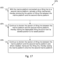
- the deployable lifting structure which is attached to the recovery platform, can safely be raised to its deployed position above the vessel and the marine platform and vessel can be lifted on board the second marine platform. Raising of the deployable lifting structure occurs automatically, Activating the lifting mechanism shortens the section of lift line between the two platforms. This raises the distal end of the lift line, thereby causing the deployable lifting structure to rise from its stowed, undeployed position to its raised, deployed position. Once the deployable lifting structure is fully deployed, continued raising of the distal end of the lift line raises the marine platform onto/into the second marine platform.
- the deployable lifting structure can be activated independently to be moved from the deployed to the undeployed position or vice versa by other mechanical actuators such as, but not limited to, hydraulic, pneumatic and electric actuators.
- the deployable lifting structure is deployed only after the vessel is hauled into the cradle, positioning the lift line of the lifting mechanism above the center of gravity of the cradle and the recovered vessel, ready to be lifted to the second marine platform.
- the deployable lifting structure is hingedly connected to the marine platform, such as the cradle disclosed herein.
- the deployable lifting structure is shaped such that, in an undeployed, stowed or horizontal, configuration, it follows the shape of the sides of the cradle so that there is clear sky above the vessel being recovered; in the stowed configuration, no part of the cradle or the deployable lifting structure extends significantly above the level of the top of the vessel's hull.
- the deployable lifting structure is connectable at its distal (top) end to a lift line which is deployed from a second marine platform.
- the distal end of the lift line When the distal end of the lift line is pulled upwards to the second marine platform, it causes the deployable lifting structure to rotate about its hinges so that it transitions to an erect, deployed, configuration, thus ensuring that the cradle plus vessel can be safely lifted.
- the deployable lifting structure Once the deployable lifting structure is in its erect configuration, continued pulling upwards of the lift line raises the cradle plus vessel (or the cradle alone) to the top of the second marine platform, where it can be safely stowed.
- the lifting structure can have a preload mechanism that keeps it in its horizontal position to ensure that it is not raised unless a sufficient pull force is provided by the lift line.
- the recovery process can be under manual control. Preferably, however, it is at least partly controlled by a computer, via instructions on a processor. Any or all of the following can be controlled by the processor: (a) deployment, maneuvering and hauling in of the tensioned capturing line; (b) maneuvering of the vessel during the capturing process; (c) maneuvering of a support stage and/or a cradle; (d) hauling a vessel on board a cradle; and (e) raising the cradle (with or without a vessel on board) to and/or onto a second marine platform.
- launching can also be controlled by the processor, with the processor causing any or all of lowering the cradle from the second marine platform, lowering a vessel from a marine platform or cradle into the sea, maneuvering the vessel and/or the capturing mechanism in the sea, and releasing the vessel from the processor's control.
- the marine environment is characterized by stochastic waves, which can carry large amounts of energy, and which create a relative motion between the marine platform and the vessel to be recovered that is practically impossible to predict in real time.
- This relative motion is in the heart of the challenge of creating a coherent and safe capturing method/device that will successfully facilitate coupling between the lifting structure and the vessel to be recovered.
- Some embodiments of the present invention are aimed at providing a device that allows an automatic, safe and coherent/consistent launch and recovery either while the recovery platform is standing still or while it is in motion at sea.
- the cradle is connected to the second marine platform by a towing line, the cradle being towed by the towing line.
- the towing line is preferably separate from and independent of both the tensioned capturing line and a lifting line.
- the vessel to be recovered is advanced, preferably using its own power, towards the trapping zone until the engagement device of the vessel (typically a hook), which is connected at the forward area of the keel stem line of the vessel with its opening facing the back of the vessel, is in the trapping zone.
- the vessel is then maneuvered, if necessary, preferably using its own power, to maintain the engagement device in the trapping zone.
- the capturing mechanism then captures the engagement device, as described hereinbelow, with the vessel outside the cradle.
- the vessel is reducing thrust power so that it becomes towed and not driven.
- the cradle is towed by the second marine platform and the vessel is towed by the cradle, while the vessel still remains outside the cradle.
- the vessel Captured by the tensioned capturing line, the vessel is now hauled onto or into the cradle, so that when the vessel is sufficiently on or in the cradle, the two move as one body.
- a crane on the second marine platform starts a lifting operation. As described hereinbelow, this raises a deployable lifting structure from a horizontal position, at the edges of the cradle and to the sides of the vessel, to an erect position above the vessel and cradle, so that the lift line is substantially over the center of gravity of the cradle plus vessel.
- the crane then continues the lifting operation until the cradle and vessel have been fully recovered onto the second marine platform.
- tension is maintained on the towing line of the cradle to increase control and safety in the lifting process.
- the engagement device opens from the sternward or rearward end, rather than from the usual bowward or forward end.
- the engagement device can incorporate a quick release mechanism.
- it can incorporate a friction reduction element such as a roller.
- it incorporates both a quick release mechanism and a friction reduction element.
- capture of the tensioned capturing line by a capturing mechanism is typically passive, not active, in that it is the contact between the capturing mechanism and the tensioned capturing line that induces the capture of the tensioned capturing line by the capturing mechanism.
- no sensors are needed to determine that contact has occurred and to command that a capturing mechanism assume its capturing configuration with the tensioned capturing line held therein.
- no human intervention is needed, either to induce contact between the capturing mechanism and the tensioned capturing line, or to induce the capturing mechanism to assume its capturing configuration.
- it is the relative motions of the tensioned capturing line and the capturing mechanism that induces capture of the tensioned capturing line by the capturing mechanism.
- the capturing mechanism is an engagement device opening from its sternward edge
- the movement of the tensioned capturing line forward relative to the vessel, with the tensioned capturing line in at least partial contact with the keel of the vessel induces the tensioned capturing line to slide into the open end of the engagement device. Thereafter, the tension in the tensioned capturing line will hold the tensioned capturing line in the engagement device.
- the engagement device can comprise a latch so that, even if tension is momentarily lost, the tensioned capturing line will remain within the engagement device.
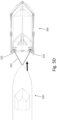
- Fig. 1 schematically illustrates the operating principle of the capturing mechanism of a launch and recovery system, in accordance with some embodiments of the present invention.
- Vessel 100 can be, for example a speedboat, an inflatable boat, a dinghy or the like. Vessels of greater dimensions are also covered by the scope of the present invention, as it is not limited to vessels of certain sizes.
- Vessel 100 is equipped with an engagement device 104 located on the keel line of vessel 100.
- an engagement device include a rearward-facing hook, as shown in Fig. 1 , a rearward-facing slot in the stem or keel of the vessel, a latch, a magnetic catch, a bridle, a pendant, a latching hook, a ratchet, a shackle or any other conventional device that can passively capture a tensioned capturing line and thereafter provide a firm engagement with the tensioned capturing line.
- the tensioned capturing line has at least one magnetic portion, with the magnetic portion can be in a central portion of the tensioned capturing line at one end of the tensioned capturing line, and any combination thereof.
- the latch opens under pressure from its outside and is forced closed by pressure from its open interior, thus obviating escape of the tensioned capturing line from the latch.
- the preloaded shackle opens under pressure from its outside and closes once the line has entered.
- the shackle can only be opened by external pressure hence the line cannot escape.
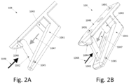
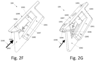
- Embodiments of engagement devices 104 are schematically illustrated in Fig. 2A-G , with Figs. 2 A and 2B illustrating one embodiment, Figs. 2C, 2D and 2E illustrating a second embodiment and Figs. 2F and 2G illustrating a third embodiment.
- Figs. 2A , 2C and 2F illustrate the engagement device 104 from the side
- Figs. 2B , 2D , 2E and 2G illustrate a perspective view of the engagement device 104 from below, so that the underside 1049 (the side resting against the vessel 100, not shown) of the engagement device 104 is seen.
- Fig. 2E illustrates a perspective, section view of the second embodiment.
- engagement devices 104 comprise a catch with a fixed part 1044 and a movable part 1042, with the movable part 1042 hingedly connected 1045 to a rigid main portion 1041.
- the underside 1049 has bolt holes 1491 for mounting the engagement device 104 to a vessel 100 (not shown).
- the engagement device 104 also comprises a roller 1043 rotatable about its vertical axis to reduce friction between the tensioned capturing line (not shown) and the engagement device during, for example towing of the vessel.
- the general direction of motion of a tensioned capturing line entering the engagement device is shown by the black arrow 1048, and the general direction of motion for a tensioned capturing line to exit (an exiting direction) from the engagement device (104) is shown by the grey arrow 1047.
- Fig. 2A-B illustrates an embodiment where the movable part 1042 of the catch is a straight bar.
- the bar 1042 is held in the closed position (shown) by a spring or a spring-like element (not shown).
- a force in an inward direction will induce the bar 1042 to rotate in a clockwise direction (patterned arrow 1046), thereby opening the catch and allowing a tensioned capturing line (not shown) to enter the open central portion of the engagement device 104.
- the spring or spring-like element holds the bar movable part 1042 against the fixed part 1044 of the catch, thereby holding the engagement device 104 in the closed position.
- a force in the exiting direction 1047 further pushes the bar movable part 1042 against the fixed part 1044 of the catch, thereby reinforcing the spring or spring-like element in holding the engagement device 104 in the closed position.
- Fig. 2C-E illustrates an embodiment where the movable part 1042 of the catch is substantially L shaped (an "L movable part"), with the hinge in approximately the center of the L.
- the L movable part 1042 is held by a spring or other spring-like element (not shown) in a position (shown) with an arm of the L, the arm 1042A, facing outwards and the other arm of the L, arm 1042B, substantially perpendicular to the rigid main portion 1041.
- a force on arm 1042B in an inward direction will induce the L movable part 1042 to rotate in a clockwise direction (patterned arrow 1046).
- a stopper 1441 Hingedly connected to the fixed part 1044 of the catch is a stopper 1441 (shown in the section view, Fig. 2E ) which can rotate about the hinge 1045.
- the stopper 1441 is normally held in an extended position by a spring or springlike element (not shown).
- the force in the inward direction will induce the L 1042 to rotate in a clockwise direction (patterned arrow 1046), thereby forcing the stopper 1441 to rotate in a counterclockwise direction, allowing the arm 1042A of the L to pass by the stopper 1441 and the fixed part of the catch 1044, allowing a tensioned capturing line (not shown) to enter the open central portion of the engagement device 104.
- the movable part of the catch (1042) will rotate clockwise by approximately 90° (patterned arrow 1046) when a tensioned capturing line enters the engagement device 104.
- one arm of the L will lie substantially within a groove 1040 in the capturing device 104, while a portion of the other arm is held on its outer side by the stopper 1441 in the fixed part 1044 of the capturing device 104.
- contact between the tensioned capturing line 212 and the L movable part 1042 is on the inside of the L, thus forming a stronger catch.
- Fig. 2F-G illustrates an embodiment where the movable part 1042 of the catch is substantially V shaped (a "V movable part"), with the hinge in approximately the center of the V.
- the V movable part 1042 is held in a closed position (shown) by a spring or other spring-like element (not shown).
- a force in an inward direction will induce the V movable part 1042 to rotate in a clockwise direction (patterned arrow 1046).
- Hingedly connected to the fixed part of the catch 1044 is a stopper 1441 (not shown; similar to that shown in Fig. 2E ) which can rotate about the hinge 1045.
- the stopper 1441 is normally held in an extended position by a spring or spring-like element (not shown).
- the force in the inward direction will induce the L 1042 to rotate in a clockwise direction (patterned arrow 1046), thereby forcing the stopper 1441 to rotate in a counterclockwise direction, allowing the arm 1042A of the L to pass by the stopper 1441 and the fixed part of the catch 1044, allowing a tensioned capturing line (not shown) to enter the open central portion of the engagement device 104.
- the spring or spring-like element pushes the stopper 1441 back to its extended position, thereby closing the catch.
- a force in the exiting direction 1047 will further push the arm 1042 A of the L against the stopper 1441 in the fixed part 1044 of the catch, thereby further holding the engagement device 104 in a closed position.
- opening of the engagement device 104 is purely mechanical.
- Pressure on the movable part 1042 by the tensioned capturing line in direction 1048 opens the device; pressure on the movable part 1042 by the tensioned capturing line in direction 1047 either ensures or helps ensure that the engagement device 104 is held in a closed position.
- the engagement device (hook 104) can be located anywhere along the keel 102 or stem 106 of the vessel at a frontal position 112. In some embodiments, the engagement device may be located at or about the waterline of vessel 100. In other embodiments, the engagement device can be located below the waterline of vessel 100. In yet other embodiments, the engagement device can be located above the waterline of vessel 100.
- the position of the engagement device is configured to correspond to the anticipated position of a tensioned capturing line that is part of a capturing mechanism in such a way that a significant part of the keel line of the vessel to be recovered is swept by the tensioned capture line before it is captured by the engagement device, in accordance with some embodiments of the present invention, which is described hereinafter.
- the tensioned capturing line (not shown, see, for example, Fig. 4B and Fig. 5 A ) is maintained in tension substantially all of the time after its initial deployment by and between two opposite arms (the line arms) (see, for example, Fig. 4B and Fig. 5A ).
- the tensioned capturing line is moved in the directions indicated by arrows 108, 110 and 114. At first, the tensioned capturing line is maintained at a predetermined depth.
- the tensioned capturing line When vessel 100 enters a trapping zone which is defined by the position and dimensions of the capturing mechanism, the tensioned capturing line will be positioned such that it is beneath the keel of the vessel, substantially transverse to the keel of the vessel, and extending across the width of the vessel, with the distance between the distal ends of the line arms (the free length of the tensioned capturing line) being greater than the width of the vessel to enlarge the capturing zone and to increase the capture success rate.
- position and dimensions of the capturing mechanism are such that the trapping zone is long enough that the position of the tensioned capturing line relative to the hull of the vessel will induce a long and effective sweeping motion along the hull, and preferably along the keel-stem line of the hull.
- the optimal position for the cable at the time of contact of the tensioned capturing line with the vessel is under the third quarter of the vessel, where the first quarter is the back of the vessel and the fourth quarter is the front of the vessel's bow.
- the tensioned capturing line is raised towards the keel, in the general direction indicated by arrow 108.
- this is actually not a straight line but a curve.
- the tensioned capturing line When it is determined that the tensioned capturing line is in contact with the keel-stem line 102-106, the tensioned capturing line is blindly swept along the keel-stem line 102-106 towards the bow of the vessel, in the direction indicated by arrow 110. During this blind sweeping process, the tensioned capturing line is maintained in contact with the keel-stem line 102-106, until it is captured by engagement device 104. In preferred embodiments, the tensioned capturing line is well aft of the engagement device 104 at the time it is raised, so that the capturing line is swept along a significant portion of the vessel's hull during its passage along the keel-stem line.
- the tensioned capturing line is secured within the engagement device 104, the tensioned capturing line is pulled in the general direction indicated by arrow 114, such that the vessel may be towed.
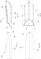
- Fig. 3 A is a schematic side view of vessel 100, with Fig. 3B showing a bottom view of vessel 100.
- Fig. 4A is a schematic side view of a cradle 200 for launch and recovery of a vessel, according to some embodiments of the present invention, with Fig. 4B showing a bottom view of the cradle 200.
- Cradle 200 generally comprises a closed or open hull 202 configured to have a rear opening 203 (more clearly shown in Figs. 5 and 6 ) or lowered wall over which vessel 100 is to be hauled onto the cradle 200.
- Cradle 200 also includes a capturing mechanism 204 that includes two substantially opposite line arms 210 between which tensioned capturing line 212 is extended.
- the line arms 210 with the tensioned capturing line 212 are located outside the perimeter of the cradle's hull, overboard, so as to allow the distal ends of the line arms 210 and the tensioned capturing line 212 to be placed beneath the vessel that is to be recovered.
- tensioned capturing line 212 is maintained tensioned between line arms 210.
- Tensioned capturing line 212 is held between two points, the distal anchors 213, which can be substantially at the distal ends of the line arms 210, can be at other locations along the line arms, or can be movable along line arms 210.
- Line arms 210 can be movable out of and into the cradle, rotatably raised or lowered about axes 222 (see Figs.
- proximal ends can be raised and lowered along an axis substantially transverse to the proximal end of the line arms 210 and, in some embodiments, can be flexed; as long as the line arms 210 maintain tensioned capturing line 212 such that it is tensioned and so that it is movable along the capture line 108-110.
- Line arms 210 are operated by one or more actuators (not shown in this figure).
- Hull 202 of the cradle 200 can include a skeg 208 for enhanced stability.
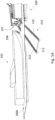
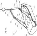
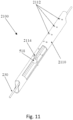
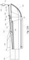
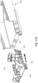
- Cradle 200 further includes a deployable lifting structure 206 (whose structure and operation of is explained hereinafter).
- tensioned capturing line 212 can be anchored to the marine platform at other points in order to ensure that the tensioned capturing line 212 can be free to move as appropriate and does not interfere with other functions of the marine platform.
- a non-limiting example of a location for an anchor is near the proximal end of the line arm 210, where the line arm is connected to the marine platform.
- FIGS. 5A-5D depict the capture process for a vessel, in accordance with some embodiments of the present invention.
- Fig. 5A schematically illustrates the entering of vessel 100 into the trapping zone of the capturing mechanism 204.
- the surface of the water is illustrated in an exemplary fashion by surface 2000; the vessel 100 and the marine platform 200 are floating, with a portion of their hulls under water.
- the distal ends of the line arms 210 of the capturing mechanism are under water, as is the tensioned capturing line 212.
- the Vessel 100 can be navigated independently (e.g., by an onboard skipper or using a remote controller or automatically using sensors and an automatic pilot system) so that the engagement device 104 is brought to within the trapping zone.
- the trapping zone (209, Fig. 4B ) is the area on the surface of the water underneath which the line arms 210 and tensioned capturing line 212 of the capturing mechanism may be positioned, whose length extends between the rear of the cradle and the furthermost position of the tensioned capturing line 212 when the line arms 210 of the capturing mechanism are deployed, and whose width is defined by the distance between the line arms 210.
- the cradle is towed.
- the cradle When the cradle is towed relative lateral movement between the cradle and the vessel is greatly reduced, which lends itself to a smoother performance of the recovery maneuver.
- the cradle can be towed by a ship (see, for example, Fig. 9 ) or other movable second marine platform, or by a winch located on a stationary platform or on shore. If cradle is not towed, it may be maneuvered by its own means such as thrusters and rudders.
- Fig. 5B schematically illustrates raising the tensioned capturing line 212 of the capturing mechanism to intercept the keel-stem line of the vessel.
- the line arms 210 with tensioned capturing line 212 of the capturing mechanism are raised until tensioned capturing line 212 engages with engagement device 104.
- the tensioned capturing line 212 is allowed to take up a V shape so as to provide a stable towing link between the towed vessel and the towing marine platform.
- the V shape can be provided by reducing the distance between the two distal anchoring holders 213, by providing a sufficient slack to the tensioned capturing line 212 e.g, by playing out some of the tensioned capturing line 212, by providing elasticity to the tensioned capturing line 212, and by any combination thereof.
- the vessel's engine is reduced to minimal throttle, thus lowering the speed of the vessel and lowering its center of gravity. Since the marine platform is now moving faster than the vessel, this allows tension to develop in tensioned capturing line 212, thereby making the capturing process of the vessel safer by making the vessel/marine platform system more stable and more controllable.
- This stage of the process ends with the vessel towed by the marine platform ( Fig. 5D ). If, as illustrated in Fig, 8 , the marine platform is recoverable onto a second marine platform, the marine platform can be towed by the second marine platform.
- the distal anchoring holders 213 can be operated, for example, via a transmission powered by the actuator.
- the distal anchoring holders 213 can stay at the distal ends of the line arms 210 as long as there is a V shape in the tensioned capturing line 212, which makes hauling of the vessel more stable, with the vessel and cradle having a low center of gravity, more controlled and therefore safer.
- the tensioned capturing line 212 can slide through the anchoring holders, such that the tensioned capturing line 212 can be pulled or released by an actuator that is located at some distance from the capturing mechanism itself.
- Fig. 5D schematically illustrates a final stage of the capturing process, with the line arms 210 vertical and the vessel towed at the stern of the marine platform 200.
- the line arms 210 can continue to rotate further, until they are fully retracted and, preferably, lying inside marine platform 200.
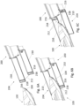
- Figs. 6A-6C schematically illustrate the capturing process, according to other embodiments of the capturing mechanism 204.
- the line arms 210 are attached to the rear of the marine platform 200.
- Each line arm comprises at least two frame rails substantially parallel to the main longitudinal axis of the line arm 210.
- the frame rails are typically of rectangular cross-section; although other cross-sections sections such as, but not limited to, semicircular cross section, can be used.
- Each line arm movably supports, on the frame rails, a vertical sliding rail 216 which is substantially perpendicular to the main longitudinal axis of the line arm 210, with each vertical sliding rail 216 controllably substantially horizontally translatable between the proximal and distal ends of its line arm 210.
- Each vertical sliding rail 216 supports a movable sliding connection element 218, with each movable sliding connection element 218 controllably translatable between the lower end and the upper end of its vertical sliding rail 216.
- Horizontal movement of the vertical sliding rails 216 and vertical movement of the sliding connection elements 218 can move the capturing line 212 in any desired direction, up, down, forward and backward and also in non-symmetrically.
- Each movable sliding connection element 218 is attached to an end of the capturing line 212.
- the capturing line 212 can be controllably played in or out by at least one winch mechanism (not shown) in communication with at least one sliding connection element 218.
- the line arms 210 may be movable relative to the cradle and may extend into the cradle.
- the capturing mechanism is configured to sweep a substantial portion of the hull of the vessel in the direction of the engagement device.
- the frames of the mechanism extend to length which is substantial relative to the length of the vessel thus allowing the capturing cable to be well behind the engagement device position before the sweeping process begins.
- the capturing cable is placed under the surface of the water in a depth greater than the maximal anticipated depth of the keel of the vessel .
- the first vertical motion of the capturing cable is sweeping the area searching for the vessel hull. This encounter may also happen while the vessel is in the air as a result of motion at sea.
- Fig. 6A schematically illustrates the bow portion of the vessel 100, the capturing mechanism 204 and the stern portion the marine platform 200 upon approach of a vessel 100 to the marine platform 200.
- the engagement device 104 has not yet entered the capturing zone.
- the line arms 210 extend into the water (not shown), so that the capturing line 212 is beneath the surface of the water.
- the vertical sliding rails 216 are at substantially their distalmost position, and the movable sliding connection elements 218 are at substantially their lowest position, so the capturing line 212 is substantially as far as possible from the marine platform 200 and as low as possible in the water.
- Fig. 6B schematically illustrates the bow portion of the vessel 100, the capturing mechanism 204 and the stern portion the marine platform 200 after the engagement device 104 has entered the capturing zone, but before it has captured the capturing line 212.
- the vessel 100 and the marine platform 200 are still free to move independently.
- the line arms 210 extend into the water (not shown), so that the capturing line 212 is beneath the surface of the water.
- the vertical sliding rails 216 are at substantially their distalmost position, and the movable sliding connection elements 218 are at substantially their lowest position, so the capturing line 212 is substantially as far as possible from the marine platform 200 and as low as possible in the water.
- the movable sliding connection elements 218 are jointly moved upward till the tensioned capturing line contacts the keel line of the vessel, than the vertical sliding rails 216 are jointly translated toward the proximal ends of the line arms 210, thus sweeping the keel line of the vessel until the tensioned capturing line encounters the engagement device.
- Fig. 6C schematically illustrates the bow portion of the vessel 100, the capturing mechanism 204 and the stern portion the marine platform 200 after the engagement device 104 has captured the capturing line 212.
- the vertical sliding rails 216 are at substantially their proximalmost position, and the movable sliding connection elements 218 have been raised.
- the capturing line 212 has been played out so that the capturing line 212 forms a V, If needed to retain the vessel 100 securely at the stern of the recovery platform 200, at least one of the following can be done: the capturing line 212 can be played in, and the movable sliding connection elements 218 can be further raised.
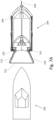
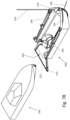
- Fig. 7A schematically illustrates a top view of a vessel approaching the trapping zone of a bow capture device of a cradle 200 for launching and recovering a vessel, according to some embodiments of the present invention.
- Fig. 7B schematically illustrates an isometric view of a vessel approaching the trapping zone of a bow capture device of a cradle for launching and recovering a vessel, according to some embodiments of the present invention.
- Fig. 8A schematically illustrates a top view of a vessel inside the trapping zone of a bow capture device of a cradle for launching and recovering a vessel, according to some embodiments of the present invention.
- Fig. 8B schematically illustrates an isometric view of a vessel inside the trapping zone of a bow capture device of a cradle for launching and recovering a vessel, according to some embodiments of the present invention.
- Tow line 240 is linked to the bow of marine platform/cradle 200 and connected to the second marine platform/towing ship (or other towing object).
- the lift line 230 and the frame line 500 of the deployable lifting structure can be continuous, so that no linkage mechanism is needed.
- lift line 230 is linked to a crane or hoist (not shown in this figure, see, for example, crane 610 in Fig. 9 ) located on the second marine platform, a ship or other large marine platform, onto which the cradle with the vessel onboard is to be recovered.
- Linkage between the lift line 230 and the frame line 500 of the deployable lifting structure 206 is at the top of the deployable lifting structure 206.
- the cradle 200 may include a support stage 400 on which the capturing mechanism 204 is mounted.
- the support stage 400 may be moved along the cradle 200, during the last stage of the recovery to the cradle (or launch).
- the bottom of cradle 200 may be designed to present substantially the same V shape angle (deadrise angle) as the bottom of the recovered vessel.
- the cradle is designed to float at a height configured to firmly press the hauled vessel onto the cradle (or the support stage), thus forcing the vessel and cradle to act as one body, preventing or greatly reducing relative motion between the cradle and the vessel.
- the cradle can be shorter than the overall length of the vessel, as long as the longitudinal center of gravity of a cradle loaded with a vessel is within the length of the cradle, so that safe lifting can be performed using the deployable lifting structure.
- Fig. 9 illustrates a recovered vessel resting on a cradle for launching and recovering a vessel, the cradle being towed by a second marine platform 600, and hooked to a crane 610 about to raise the cradle onto the second marine platform 600, according to some embodiments of the present invention.
- Tow line 240 is secured to the second marine platform at a predetermined point (preferably at a frontal portion of the second marine platform, and can be linked at all times to the cradle, while the lift line 230 of crane 610 is linked to the top of deployable lifting structure 206 at constant tension.
- Both lines are linked to the cradle throughout the recovery process, to reduce yawing of the cradle (with or without the vessel on top of it) and to ensure that the cradle (with or without the vessel) maintains a predetermined course some distance away from the second marine platform's side.
- a desired distance between the cradle and the second marine platform can be maintained, for example, by a set of rudders or thrusters, either fixed or controllable, on the cradle or by a structure of some form that keeps the cradle at a safe distance from the second marine platform.
- Fig. 10 illustrates a cradle for launching and recovering a vessel, with its deployable lifting structure being raised, according to some embodiments of the present invention. It is noted that until the completion of hauling of the vessel 100 onto cradle 200, deployable lifting structure 206 is maintained in its stowed configuration, to allow the vessel to be the more safely hauled, since, with the deployable lifting structure 206 stowed, 'clear sky' is maintained above the cradle and the vessel.
- the frame of the deployable lifting structure 206 is shaped so as to substantially conform to the contour of the rim of the cradle's side and front walls, so that the frame rests over the rim (thus substantially horizontal) when in the stowed configuration.
- the deployable lifting structure 206 may also be shaped such that it extends outward beyond the rim of the cradle's walls. In less-preferred embodiments of the present invention, the deployable lifting structure 206 may also be shaped such that it protrudes into the space defined by the rim of the cradle's walls, but that would have its drawbacks as it can take up space in or over the interior of the cradle and would require planning a larger cradle in order to have room to accommodate both the vessel and the deployable lifting structure 206 within the cradle walls.
- Deployable lifting structure 206 can include two substantially opposite frame bars 512 pivotally connected by hinges 506, to substantially opposite positions at the sides of the cradle, and a V-shaped (or U-shaped or straight shaped) structure 514. Each of the ends of V- or U- or straight- shaped structure 514 is connected, via a hinge 508, to one of the frame bars 512.
- the hinges 506 are forward of the longitudinal center of gravity of the cradle, and preferably forward of the expected longitudinal center of gravity of the cradle with a vessel aboard.
- the frame bars 512 can be connected, as shown herein, to the cradles' side wall, or they can stand free of the cradle's walls, being attached to, for non-limiting example, the bottom of the cradle.
- the ends of frame line 500 are each secured to a rear position 516 on either of the cradle 200, aft of the longitudinal center of gravity of the cradle, and preferably aft of the expected longitudinal center of gravity of the cradle with a vessel aboard.
- the frame line 500 is coupled to deployable lifting structure 206 in at least at three positions: two substantially opposite loops 502 located on either sides of the frame (about the ends of V-shaped bar 514) and at the top of the frame, at the center of V-shaped bar 514.
- the frame line 500 is allowed to move within the loops, and is linked to lift line 230 (or, in some embodiments, is an integral part of lift line 230), so that, when the crane starts pulling lift line 230, deployable lifting structure 206 starts to rise up.
- Limiters 518 can be placed on frame line 500 so as to limit the movement of the deployable lifting structure 206 such that it stops the deployable lifting structure 206 from moving beyond a predetermined angle with respect to the cradle. Therefore, the lifting point is positioned substantially above the center of gravity of the cradle or of a cradle containing a vessel. In its deployed position, the deployable lifting structure and the marine platform is a stable structure based on the tensioned lift line on one side of the deployable lifting structure and the limiters which define the deployed position.
- the frame line can be coupled to the deployable lifting structure 206 via couplers or by being incorporated at least partially inside the deployable lifting structure's frame bars.
- Couplers can be loop-like, tube-like or any other conventional means of guiding the frame line so that it at least partially follows the contours of the deployable lifting structure.
- Limiters can be provided on the frame line so as to stop the deployable lifting structure from moving beyond a predetermined position above the marine platform.
- the limiters comprise transverse extensions to the frame line. In embodiments such as those with a transverse extension, raising of the frame can terminate when further movement of a limiter is prevented by contact of the limiter with: a coupler, a hole where a frame line enters the frame, a stopping mechanism, and any combination thereof.
- Fig. 11 illustrates an embodiment of a stopping mechanism 2100.
- the stopping mechanism 2100 comprises sleeve 2110 with holes 2112.
- the stopping mechanism can comprise a coupler, or it can form part of one of the frame bars.
- the holes 2112 in the sleeve 2110 are shaped and sized such that a stopper 2114, in this embodiment, a U-shaped stopper, can pass therethrough.
- the stopper 2114 is shaped and sized such that the frame line 230 can pass freely therethrough, but the limiter 518 cannot pass therethrough so that, when a limiter 518 contacts a stopper 2114, further movement of the frame line 230 is prevented.
- This embodiment of the stopping mechanism 2100 illustrates an adjustable stopping mechanism, in that the distance the frame line 230 travels and, therefore, the maximum angle between the deployable lifting structure and the cradle is determined by the longitudinal position of the pair of holes 2112 the stopper 2114 is inserted in.
- Deployable lifting structure 206 combines a structural frame assembly (comprising 514 and 512) with frame lines 500.
- the frame assembly and frame lines 500 are connected to the marine platform (in the illustrated case, the cradle) at points 506 and 516 respectively. Points 506 and 516 are configured such that the center of gravity of the entire lifted weight (in the illustrated case, the cradle with the vessel on board) lies in between them.
- frame line 500 is pulled by lifting line 230 of the crane, it slides through to couplers 502 causing the frame to rise until the lifting line 230 is located substantially above the center of gravity.
- the limiters 518 are designed such that when the limiters are mechanically blocked by the couplers 502 the structure is fixed in a lifting geometry. At this stage, the load of the weight is carried by the frame lines 500, the limiters and the frame assembly, which are under tension.
- the entire configuration of this assembly is assembled in a reversed orientation, with the frame assembly connected at the aft points 516, aft of the center of gravity, and the frame lines 500 at the forward points 506, forward of the center of gravity.
- the top of the deployable lifting structure 206 is above the longitudinal center of gravity of a cradle (or other marine platform) 200 with a vessel 100 on board.
- the longitudinal position of the top of the deployable lifting structure 206, and therefore the longitudinal position of the lift line 230 is substantially the same as the longitudinal position of the center of gravity of the cradle (or other marine platform) 200 with a vessel 100 on board.
- the top of the deployable lifting structure 206 is above the transverse center of gravity of a cradle (or other marine platform) 200 with a vessel 100 on board.
- the transverse center of gravity of the cradle (or other marine platform) 200 with a vessel 100 on board will be substantially along the keel or stem of the vessel.
- Fig. 12A illustrates a cradle 200 for launching and recovering a vessel with its deployable lifting structure 206 in a stowed configuration, according to some embodiments of the present invention.
- Fig. 12B illustrates a cradle 200 for launching and recovering a vessel s with its deployable lifting structure 206 in its erect configuration, according to some embodiments of the present invention.
- the positions 516 of the connection of frame line 500 to the cradle, the positions of hinges 506 and the position 518 of the limiters are configured such that the anticipated center of gravity of the cradle 200 with a vessel on top of it lies substantially under the top of the erected deployable lifting structure 206.
- Fig. 13A is a side view of a system for launch and recovery of a marine vessel, according to some embodiments of the present invention, with a movable support stage 400 on which capturing mechanism 204 is mounted (separated).
- the support stage 400 can be designed to move inside of the cradle along a predetermined track.
- the predetermined track can comprise a bottom protruding slider 401 extending from the base of the support stage 400, and a matching groove on the cradle.
- the bottom protruding slider 401 can be inserted the groove and can move along that groove.
- Fig. 13B shows a rear view of a system for launch and recovery of a vessel, according to some embodiments of the present invention, with the movable support stage 400.
- Fig. 13C is an isometric view of a system for launch and recovery of a vessel, according to some embodiments of the present invention, with a movable support stage 400 (separated).
- Matching groove 403 is shown at the bottom of cradle 200.
- slider 401 is inserted into groove 403
- movable support stage 400 can move inside cradle 200 along the groove (which extends across the bottom of the cradle, substantially parallel to the keel line of the cradle.
- Fig. 14A-14C illustrate hauling a vessel onto a marine platform, according to some embodiments of the present invention.
- the vessel is shown at an initial hauling stage.
- the vessel is shown at an intermediate hauling stage.
- the vessel is shown at a final hauling stage.
- a launch operation is quite similar to the recovery operation, except that it is carried out in reverse. In some embodiments, launching of the vessel off the cradle does not require the use of the capturing mechanism, while in other embodiments the capturing mechanism can be employed.
- the operation of the launch and recovery system can be fully automatic, partially automatic or fully manual.
- FIG. 15 A schematic illustration of a fully automatic launch and recovery system, according to some embodiments, is shown in Fig. 15 .
- System 900 includes a sensor or sensors 902 to detect various events, such as, for example, identification that at least one vessel is in the trapping zone, entry of the engagement device of the vessel into the trapping zone of the capturing mechanism, lack of contact between the tensioned capturing line 212 and the keel or stem line of the vessel, at least partial contact between at least one tensioned capturing line 212 and at least one keel or stem line of the vessel, engagement of the tensioned capturing line 212 with the engagement device, completion of capturing by the engagement device, completion of hauling of the vessel, changes in the state of the capturing mechanism, changes in the position of said capturing mechanism, and other events.
- events such as, for example, identification that at least one vessel is in the trapping zone, entry of the engagement device of the vessel into the trapping zone of the capturing mechanism, lack of contact between the tensioned capturing line 212 and the keel or stem line of the vessel, at least partial contact between at least one tensioned capturing line 212 and at least
- a tension sensor for example, a tension sensor, a pressure sensor, an optical sensor, a proximity sensor, a force sensor, a position sensor, a speed sensor, an acceleration sensor, an acoustic sensor, a vibration sensor, a tilt sensor, a strain gauge, and any combination thereof can be used.
- processor/controller 908 (hereinafter, the term "processor” is used to refer either to a processor or to a controller) which executes an algorithm for recovery or launch of a vessel, and the processor issues operational commands and/or data to the capturing mechanism to operate it in a manner that would facilitate successful recovery or launch of the vessel.
- the processor is configured, upon detection of the engagement device of the vessel within the trapping zone, to activate the capturing mechanism until the tensioned capturing line 212 is engaged with the engagement device.
- the processor can also be configured, upon detection of the tensioned capturing line 212 engaged with the engagement device, to authorize or cause reduction of thrust in the vessel.
- the processor can also be configured, upon detection of completion of capturing process, to cause hauling of the vessel onto the marine platform. Further, the processor can be configured, upon detection of completion of the hauling process, to cause commencement of lifting of the vessel and marine platform to the second marine platform.
- Input interface 910 can be included to allow a user to enter data and/or commands.
- Fig. 16 illustrates a method 950 for recovery of a marine vessel to a marine platform, according to some embodiments.
- a tensioned capturing line 212 of a capturing mechanism is placed 952 below the surface of the sea. If necessary, at least one of the vessel, marine platform and capturing mechanism is maneuvered 954 until the engagement device of the vessel enters the capturing mechanism's trapping zone, so that the tensioned capturing line 212 is beneath the keel or stem of the vessel. Once the vessel 100 is in the trapping zone, the tensioned capturing line 212 is raised 956 until it contacts the keel or stem of the vessel.
- the tensioned capturing line 212 is moved toward the engagement device, while maintaining it in contact with the keel or stem, until the tensioned capturing line 212 is engaged with the engagement device.
- the speed of the vessel is reduced to put tension in the tensioned capturing line 212, thereby inducing the tensioned capturing line 212 to assume a "V" shape.
- the tensioned capturing line 212 is then drawn in, drawing the vessel to the stern of the cradle.
- the vessel is drawn onto the cradle, either with or without the aid of a movable support stage 400.
- the marine platform and vessel can then be lifted onto the second marine platform using a lifting device, such as a crane, hoist or davit which may be installed on the second marine platform, as illustrated in Fig. 17 .
- Fig. 17 illustrates a method 970 for recovery of a marine platform, with or without a vessel on board, to a second marine platform, according to some embodiments.
- the marine platform is connected to a lift line attached to a hoist, crane, davit or other lifting device on a second marine platform.
- the lifting device is activated 972, causing the section of lift line between the lifting device and the marine platform to be shortened ("shortening the lifting line"). This induces the deployable lifting structure to rise from its stowed position to its erect position 974.
- the lifting device or an auxiliary maneuvering device can maneuver the marine platform horizontally so as to place it in a safe stowing position on board the second marine platform.
- Portions of the system utilizing automatic control can be embodied as hardware, software or a combination of both.
- a set of instructions to be executed by a user or a manual for the user can be used.
- the manual can be either embodied by means of a hard copy (such as a printed book) or as a computer-readable "soft copy".
- the instructions to be executed are displayed on an "as needed" basis.
- the automatic control system or systems can be embodied as a computer program product saved on one or more non-transitory computer readable or media, in the form of computer readable program code.
- the instructions can be in the form of an installed application or in the form of an installation package, or can be downloaded from a remote storage medium such as, but not limited to, the Internet, a remote server, or the cloud.
- the instructions can cause a processor to execute method steps in accordance with the examples above, such as, but not limited to, the embodiment shown in Figs. 13 and 14 .
- a non-transitory computer readable storage medium can be, for example, an electronic, optical, magnetic, electromagnetic, infrared, or semiconductor system, apparatus, or device, or any combination thereof.
- Computer program code can be written in any suitable programming language.
- the program code can execute on a single computer system, or on a plurality of computer systems.
- an automatic control system can additionally comprise instructions to lift the marine platform plus vessel onto a second marine platform.
- steering of the vessel and/or control of the speed of the vessel is done manually.
Landscapes
- Engineering & Computer Science (AREA)
- Mechanical Engineering (AREA)
- Ocean & Marine Engineering (AREA)
- Chemical & Material Sciences (AREA)
- Combustion & Propulsion (AREA)
- Cleaning Or Clearing Of The Surface Of Open Water (AREA)
- Filling Or Discharging Of Gas Storage Vessels (AREA)
- Processing Of Solid Wastes (AREA)
- Driving Mechanisms And Operating Circuits Of Arc-Extinguishing High-Tension Switches (AREA)
- Cleaning In General (AREA)
Claims (14)
- Eine Schiffsplattform (200) mit einem an der Schiffsplattform (200) befestigten Einfangmechanismus (204) für ein System zum Zurückholen mindestens eines Wasserfahrzeugs (100) zu der Schiffsplattform (200), wobei der Einfangmechanismus (204) Folgendes umfasst:a. mindestens eine gespannte Einholleine, die mit der Schiffsplattform (200) verbunden ist;b. mindestens einen Leinenkontrollmechanismus (210), undc. mindestens eine Eingriffsvorrichtung (104), die mit dem Wasserfahrzeug (100) verbindbar ist,
dadurch gekennzeichnet, dassder mindestens eine Leinenkontrollmechanismus zwei Leinenarme (210) mit einem distalen Ende und einem proximalen Ende umfasst, wobei die mindestens eine gespannte Einholleine (212) mit dem distalen Abschnitt der Leinenarme (210) verbunden ist und das proximale Ende mit der Schiffsplattform (200) verbunden ist; und ein oder mehrere Antriebselemente,wobei die zwei Leinenarme (210) von den einen oder mehreren Antriebselementen betätigt werden und die mindestens eine gespannte Einholleine (212) in eine Vielzahl von Richtungen bewegen, bestehend aus aufwärts, abwärts, vorwärts, rückwärts, spielbar in die Schiffsplattform, spielbar aus der Schiffsplattform, um die Einholleine (212) in das Wasser und aus dem Wasser spielbar zu machen;wobei die mindestens eine gespannte Einholleine (212) im Wesentlichen die ganze Zeit nach ihrer ersten Bereitstellung von und zwischen den beiden gegenüberliegenden Leinenarmen (210) unter Spannung gehalten wird, wobei die mindestens eine gespannte Leine während ihres Einholens außerhalb der Schiffsplattform (200) in einer Tiefe unterhalb der Meeresoberfläche platziert ist, die größer ist als eine Tiefe eines Kiels (102) des mindestens einen Wasserfahrzeugs (100);und dadurch, dassder Einfangmechanismus (204) ausgebildet ist, um die mindestens eine gespannte Einholleine (212) blind entlang einem substantiellen Abschnitt von, und in Kontakt mit, einer Kiel-Vordersteven-Linie (102, 106) des mindestens einen Wasserfahrzeugs (100) zu der Eingriffsvorrichtung (104) zu bewegen, bis zumindest partieller Kontakt zwischen der mindestens einen gespannten Einholleine (212) und der Eingriffsvorrichtung (104) hergestellt ist, wobei die mindestens eine gespannte Einholleine (212) von der Eingriffsvorrichtung (104) bei dem zumindest partiellen Kontakt zwischen derselben und der mindestens einen gespannten Einholleine (212) erfasst werden kann. - Die Schiffsplattform (200) mit dem Einfangmechanismus gemäß Anspruch 1, wobeia. das Erfassen der mindestens einen gespannten Einholleine (212) von der Eingriffsvorrichtung (104) zumindest teilweise reversibel ist;b. jeder der beiden Leinenarme (210) weiter dadurch gekennzeichnet ist, dass er an dem distalen Ende mit mindestens einem Verankerungshalter (213) für die mindestens eine gespannte Einholleine (212) ausgestattet ist, wobei der mindestens eine Verankerungshalter entweder beweglich entlang dem mindestens einen Leinenarm (210) oder in einer festen Position entlang dem mindestens einen Leinenarm (210) ist; und/oderc. mindestens ein Mechanismus bereitgestellt ist, ausgebildet, um die Entstehung einer "V"-Form in mindestens einem Abschnitt der mindestens einen gespannten Einholleine (212) nach dem Erfassen der mindestens einen gespannten Einholleine durch die Eingriffsvorrichtung (104) zu ermöglichen;
wobei der Mechanismus Folgendes ist: einem Mechanismus zum Abspielen mindestens eines Teils der mindestens einen gespannten Einholleine und/oder ein Mechanismus, um mindestens zwei der Verankerungshalter näher zueinander zu bewegen, und/oder ein Mechanismus, um der mindestens einen gespannten Einholleine Elastizität zu verleihen; und/oderd. die Schiffsplattform mindestens ein Schlitten (200) ist;
und/odere. die Schiffsplattform an einem Heck (203) derselben offen ist; und/oderf. die Form der Schiffsplattform (200) geeignet ist, entweder das Hindurchströmen von Wasser durch dieselbe zu gestatten oder das Hindurchströmen von Wasser durch dieselbe nicht zu gestatten; und/oderg. mindestens ein Teil des mindestens einen eingeholten Wasserfahrzeugs (100) auf mindestens einen Teil der Schiffsplattform (200) gezogen werden kann; und/oderh. die Schiffsplattform (200) eine ausfahrbare Hebestruktur (206) hat; und/oderi. die Schiffsplattform mittels mindestens eines Hebemechanismus auf eine zweite Schiffsplattform gehoben werden kann, entweder so, dass die Schiffsplattform kein Wasserfahrzeug trägt, oder so, dass die Schiffsplattform das mindestens eine Wasserfahrzeug zumindest teilweise trägt; undj. die Schiffsplattform (200) durch mindestens ein Schlepptau (240) mit der zweiten Schiffsplattform verbindbar ist,
wobei das mindestens eine Schlepptau (240) ausgebildet ist, um (a) unerwünschte Bewegung der Schiffsplattform während des Ziehens des mindestens einen eingeholten Wasserfahrzeugs auf die Schiffsplattform einzuschränken; (b) unerwünschte Bewegung der Schiffsplattform während des Ablassens des mindestens einen Wasserfahrzeugs von der Schiffsplattform einzuschränken; (c) unerwünschte Bewegung der Schiffsplattform während des Bewegens des mindestens einen Wasserfahrzeugs auf die Schiffsplattform einzuschränken; (d) die Bewegung der Schiffsplattform relativ zu der zweiten Schiffsplattform einzuschränken. - Die Schiffsplattform (200) mit dem Einfangmechanismus gemäß Anspruch 1,wobei die Schiffsplattform (200) zusätzlich mindestens eine bewegliche Tragebühne (400) umfasst, undwobeia. mindestens ein Teil des mindestens einen eingeholten Wasserfahrzeugs (100) auf mindestens einen Teil der mindestens einen beweglichen Tragebühne (400) gehoben wird; und/oderb. mindestens ein Teil der mindestens einen beweglichen Tragebühne (400) auf mindestens einen Teil der Schiffsplattform (200) gezogen werden kann.
- Die Schiffsplattform (200) mit einem Einfangmechanismus gemäß Anspruch 1, wobei die Eingriffsvorrichtung (104) des Wasserfahrzeugs (100) mindestens eines von Folgendem ist:a. ein rückwärts gerichteter Haken; oderb. eine Magnetklinke;
wobei die mindestens eine gespannte Einholleine (212) mindestens einen magnetischen Abschnitt hat; wobei der mindestens eine magnetische Abschnitt sich im Wesentlichen in r Folgendem befindet: (a) der Mitte der mindestens einen gespannten Einholleine und/oder (b) an einem Ende der mindestens einen gespannten Einholleine; oderc. ein rückwärts gerichteter Schlitz in einem Vordersteven oder Kiel des mindestens einen Wasserfahrzeugs (100); und wobei die mindestens eine gespannte Einholleine (212) mit mindestens einer Führung ausgestattet ist, ausgebildet, um in den Schlitz einzugreifen und die mindestens eine gespannte Einholleine (212) in den Schlitz eindringen zu lassen; oderd. eine rückwärts gerichtete Klinke; die rückwärts gerichtete Klinke ist ausgebildet, um unter Druck von außen geöffnet werden zu können und automatisch verschließbar zu sein; wobei Druck von ihrer Innenseite das Öffnen der Klinke physisch verhindert, so dass der Austritt der mindestens einen gespannten Einholleine aus der rückwärts gerichteten Klinke verhindert wird. - Die Schiffsplattform (200) mit dem Einfangmechanismus gemäß Anspruch 1, wobei mindestens ein Sensor an der Schiffsplattform (200) und/oder dem Einfangmechanismus (204) angebracht ist,wobei der mindestens eine Sensor mindestens eines von Folgendem ist: einem Spannungssensor, einem Drucksensor, einem optischen Sensor, einem Näherungssensor, einem Kraftsensor, einem Positionssensor, einem Geschwindigkeitssensor, einem Beschleunigungssensor, einem akustischen Sensor, einem Vibrationssensor, einem Neigungssensor, einem Dehnungsmesser; undwobei der mindestens eine Sensor mindestens eines von Folgendem ist:a. dem Bestimmen, dass das mindestens eine Wasserfahrzeug (100) sich in einer Einfangzone befindet, wobei die Einfangzone ein solcher Bereich ist, dass, wenn sich die mindestens eine Eingriffsvorrichtung (104) in der Einfangzone befindet, die Bewegung der mindestens einen gespannten Einholleine (212) zum Kiel oder Vordersteven und das anschließende Bewegen der mindestens einen gespannten Einholleine zu der Eingriffsvorrichtung (104) hin, während sie sich in Kontakt mit dem Kiel oder Vordersteven des Wasserfahrzeugs (100) befindet, in Kontakt zwischen der mindestens einen gespannten Einholleine (212) und der Eingriffsvorrichtung resultiert;b. Eintritt der mindestens einen Eingriffsvorrichtung (104) des mindestens einen Wasserfahrzeugs (100) in die Einfangzone des Einfangmechanismus (204);c. mindestens partieller Kontakt zwischen der mindestens einen gespannten Einholleine (212) und der mindestens einen Kiel- oder Vordersteven-Linie eines Wasserfahrzeugs (100);d. fehlender Kontakt zwischen der mindestens einen gespannten Einholleine (212) und der mindestens einen Kiel- oder Vordersteven-Linie eines Wasserfahrzeugs (100) ;e. Abschluss des Einholens der Eingriffsvorrichtung (104);f. Abschluss des Heranziehens des mindestens einen eingefangenen Wasserfahrzeugs (100);g. mindestens eine Positionsänderung mindestens eines Teils des Einfangmechanismus (204).
- Die Schiffsplattform (200) mit dem Einfangmechanismus gemäß Anspruch 2,
wobeidie mindestens eine ausfahrbare Hebestruktur (206) an ihrem unteren Ende mit der Schiffsplattform (200) und an ihrem oberen Ende mit einer Hebevorrichtung, wie zum Beispiel einem Kran, verbunden ist;wobei die mindestens eine ausfahrbare Hebestruktur (206) mindestens zwei Konfigurationen hat: eine verstaute Konfiguration, die im Wesentlichen horizontal mit Bezug auf die Seiten der Schiffsplattform (200) ist, so dass sie ein sicheres Ziehen eines Wasserfahrzeugs (100) auf die Schiffsplattform ohne Elemente der verstauten Hebestruktur oberhalb des herangezogenen Wasserfahrzeugs (100) gestattet; und eine senkrechte Konfiguration, die im Wesentlichen so senkrecht ist, dass ein Schwerpunkt der Schiffsplattform (200), mit oder ohne ein Wasserfahrzeug an Bord, sich im Wesentlichen unterhalb des oberen Endes der ausfahrbaren Hebestruktur (206) in ihrer senkrechten Konfiguration befindet; wobei der Wechsel der ausfahrbaren Hebestruktur (206) zwischen der verstauten und der senkrechten Konfiguration während eines Start- und Anlandevorgangs durchführbar ist;und wobei die ausfahrbare Struktur (206):a. so geformt ist, dass sie in der verstauten Konfiguration im Wesentlichen den Außenseiten und der vorderen Kontur der Schiffsplattform (200) entspricht; und/oderb. mindestens zwei im Wesentlichen gegenüberliegende Rahmenstäbe (512) umfasst, wobei die Rahmenstäbe ein distales Ende und ein proximales Ende haben, wobei eine Verbindung die distalen Enden der Rahmenstäbe (512) miteinander verbindet, wobei die proximalen Enden der mindestens zwei Rahmenstäbe schwenkbar mit im Wesentlichen gegenüberliegenden Seitenpositionen der Schiffsplattform (200) verbunden sind; und/oderc. weiter mindestens einen Führungsmechanismus umfasst, wobei der Führungsmechanismus eines von Folgendem ist: einer Kupplung und einem Inneren der ausfahrbaren Hebestruktur; wobei mindestens eine Rahmenlinie (500) durch den mindestens einen Führungsmechanismus verläuft, so dass die mindestens eine Rahmenlinie an ihrem oberen Ende gezogen werden kann, so dass, wenn das obere Ende der mindestens einen Rahmenlinie (500) gezogen wird, die mindestens eine ausfahrbare Hebestruktur (206) ausgebildet ist, um aus der verstauten Konfiguration in die senkrechte Konfiguration gehoben zu werden; und/oderd. zusätzlich mindestens zwei Begrenzungsvorrichtungen (518) umfasst, ausgebildet, um einen maximalen Winkel der mindestens einen ausfahrbaren Hebestruktur im Verhältnis zu der Schiffsplattform (200) zu begrenzen, wobei die Begrenzungsvorrichtungen (518) so ausgebildet sind, dass ein Schwerpunkt der Schiffsplattform, mit oder ohne ein Wasserfahrzeug an Bord, sich im Wesentlichen unter dem oberen Ende der ausfahrbaren Hebestruktur (206) in ihrer senkrechten Konfiguration befindet, wobei der maximale Winkel, der begrenzt werden kann durch Verhindern einer Bewegung der Begrenzungsvorrichtungen (518) in mindestens einer Richtung entlang der ausfahrbaren Hebestruktur, in einer stabilen Hebeanordnung resultiert; wobei die Bewegung der Begrenzungsvorrichtungen verhindert werden kann durch:mindestens einen Führungsmechanismus und/oder ein Loch,an dem eine Rahmenlinie in den Rahmen eintritt, und/oder einen Stoppmechanismus. - Ein Verfahren zum Zurückholen, mit Hilfe einer Schiffsplattform (200) mit einem Einfangmechanismus (204) wie in Anspruch 1 für ein Rückholsystem ausgeführt, mindestens eines Wasserfahrzeugs (100) zu der Schiffsplattform (200), wobei das mindestens eine Wasserfahrzeug (100) mindestens eine Eingriffsvorrichtung (104) hat, die mit derselben verbindbar ist; folgende Schritte umfassend:a. das Verbinden mindestens einer gespannten Einholleine (212) mit der Schiffsplattform (200);b. das Bereitstellen mindestens eines Leinenkontrollmechanismus (210), ausgebildet, um die mindestens eine gespannte Einholleine (212) in einer Vielzahl von Richtungen zu versetzen, bestehend aus aufwärts, abwärts, vorwärts, rückwärts, spielbar in die Schiffsplattform, spielbar aus der Schiffsplattform, um die Leine (212) in das Wasser und aus dem Wasser spielbar zu machen; und das Platzieren der gespannten Einholleine (212) außerhalb der Plattform in einer Tiefe unterhalb der Meeresoberfläche, die größer ist als eine Tiefe eines Kiels (102) des mindestens einen Wasserfahrzeugs (100);c. das Manövrieren eines Bugs des mindestens einen Wasserfahrzeugs (100) in eine Einfangzone der Schiffsplattform (200), wobei die Einfangzone ein solcher Bereich ist, dass, wenn sich die mindestens eine Eingriffsvorrichtung (104) in der Einfangzone befindet, die Bewegung der mindestens einen gespannten Einholleine (212) zum Kiel oder Vordersteven und das anschließende Bewegen der mindestens einen gespannten Einholleine zu der Eingriffsvorrichtung hin, während sie sich in Kontakt mit dem Kiel oder Vordersteven des Wasserfahrzeugs (100) befindet, in Kontakt zwischen der mindestens einen gespannten Einholleine und der Eingriffsvorrichtung resultiert;d. das Anheben der mindestens einen gespannten Einholleine (212), wenn das mindestens eine Wasserfahrzeug (100) sich in der Einfangzone befindet; und das Halten mindestens partiellen Kontakts zwischen der mindestens einen gespannten Einholleine (212) und dem Kiel oder Vordersteven; unde. das Einspielen der mindestens einen gespannten Einholleine (212) bei gleichzeitigem blindem Bewegen der mindestens einen gespannten Einholleine entlang einem substantiellen Abschnitt einer Kiel-Vordersteven-Linie (102, 106) des mindestens einen Wasserfahrzeugs zu der Eingriffsvorrichtung und bei gleichzeitigem Halten zumindest partiellen Kontakts zwischen der mindestens einen gespannten Einholleine (212) und dem Kiel (102) oder Vordersteven (106), um die mindestens eine gespannte Einholleine in Kontakt mit mindestens einer Eingriffsvorrichtung zu bringen, wobei der Kontakt im Einfangen der mindestens einen gespannten Einholleine (212) durch die mindestens eine Eingriffsvorrichtung (104) resultiert; und wahlweise weiter einen oder mehrere der folgenden Schritte umfassend:f. mindestens teilweise reversibles Einfangen der mindestens einen gespannten Einholleine (212) durch die Eingriffsvorrichtung (104);g. Ausstatten des mindestens einen Leinenkontrollmechanismus mit zwei Leinenarmen (210), wobei die Leinenarme (210) ein distales Ende und ein proximales Ende haben; das Verbinden der mindestens einen gespannten Einholleine (212) mit dem distalen Abschnitt der beiden Leinenarme (210) und das Verbinden des proximalen Endes mit der Schiffsplattform (200);h. Ausstatten jedes der mindestens zwei Leinenarme (210) mit mindestens einem Verankerungshalter (213) für die mindestens eine gespannte Einholleine (212), wobei der Verankerungshalter entweder beweglich entlang dem Leinenarm (210) oder in einer festen Position in dem Leinenarm ist, und, wenn der Verankerungshalter (213) entlang dem Leinenarm beweglich ist, das Bewegen des mindestens einen Verankerungshalters (213) entlang dem mindestens einen Leinenarm (210);i. Ermöglichen der Entstehung einer "V"-Form in mindestens einem Abschnitt der mindestens einen gespannten Einholleine (212) nach dem Einfangen der mindestens einen gespannten Einholleine durch die Eingriffsvorrichtung (104) durch:Abspielen mindestens eines Abschnitts der mindestens einen gespannten Einholleine (212),Ermöglichen der gegenseitigen Annäherung der zwei Verankerungshalter (213),Versehen der gespannten Einholleine (212) mit Elastizität, und jede beliebige Kombination davon;j. Bereitstellen der Schiffsplattform als mindestens ein Schlitten (200);k. Bereitstellen der Schiffsplattform (200), offen an einem Heck (203) derselben;l. Versehen der Schiffsplattform (200) mit einer Form, die es entweder ermöglicht, dass Wasser durch sie hindurchströmt, oder es nicht ermöglicht, dass Wasser durch sie hindurchströmt;m. mindestens partielles Heraufziehen des mindestens einen eingefangenen Wasserfahrzeugs (100) auf mindestens einen Teil der Schiffsplattform (200);n. Ausstatten der Schiffsplattform (200) mit einer ausfahrbaren Hebestruktur (206);o. Heben der Schiffsplattform (200) auf eine zweite Schiffsplattform mit Hilfe mindestens eines Hebemechanismus, entweder so, dass die Schiffsplattform (200) kein Wasserfahrzeug trägt, oder so, dass die Schiffsplattform (200) das mindestens eine Wasserfahrzeug zumindest teilweise trägt;p. Verbinden der Schiffsplattform (200) mit der zweiten Schiffsplattform durch mindestens ein Schlepptau (240), wobei das mindestens eine Schlepptau ausgebildet ist, um (a) unerwünschte Bewegung der Schiffsplattform während des Ziehens des mindestens einen eingeholten Wasserfahrzeugs (100) auf die Schiffsplattform (200) einzuschränken; (b) unerwünschte Bewegung der Schiffsplattform (200) während des Ablassens des mindestens einen Wasserfahrzeugs (100) von der Schiffsplattform einzuschränken; (c) unerwünschte Bewegung der Schiffsplattform (200) während des Bewegens des mindestens einen Wasserfahrzeugs (100) auf die Schiffsplattform einzuschränken; (d) die Bewegung der Schiffsplattform (200) relativ zu der zweiten Schiffsplattform einzuschränken; und jede beliebige Kombination davon.
- Das Verfahren gemäß Anspruch 7,das zusätzlich einen Schritt des Ausstattens der Schiffsplattform (200) mit mindestens einer beweglichen Tragebühne (400) umfasst, unddas weiter zusätzlich mindestens einen der folgenden Schritte umfasst:a. Anheben mindestens eines Teils des mindestens einen eingefangenen Wasserfahrzeugs (100) auf mindestens einen Teil der mindestens einen beweglichen Tragebühne (400);b. Ziehen mindestens eines Teils der mindestens einen beweglichen Tragebühne (400) auf mindestens einen Teil der Schiffsplattform (200);c. Ausstatten der mindestens einen beweglichen Tragebühne (400) mit mindestens einem Flügel und Ausstatten der Schiffsplattform (200) mit mindestens einer Nut, mit welcher der mindestens eine Flügel beweglich ist.
- Das Verfahren gemäß Anspruch 7, wobei die mindestens eine Eingriffsvorrichtung (104) Folgendes ist:a. ein rückwärts gerichteter Haken; und/oderb. eine Magnetklinke; wobei die mindestens eine gespannte Einholleine (212) mindestens einen magnetischen Abschnitt hat; wobei der mindestens eine magnetische Abschnitt sich im Wesentlichen in entweder (a) der Mitte der mindestens einen gespannten Einholleine; (b) an einem Ende der mindestens einen gespannten Einholleine und einer beliebigen Kombination davon befindet; und/oderc. ein rückwärts gerichteter Schlitz in einem Vordersteven (106) oder Kiel (102) des mindestens einen Wasserfahrzeugs (100); und wobei die mindestens eine gespannte Einholleine (212) mit mindestens einer Führung ausgestattet ist, ausgebildet, um in den Schlitz einzugreifen und die mindestens eine gespannte Einholleine in den Schlitz eindringen zu lassen; und/oderd. eine rückwärts gerichtete Klinke, die ausgebildet ist, um unter Druck von außen geöffnet werden zu können und automatisch verschließbar zu sein; wobei Druck von ihrer Innenseite das Öffnen der Klinke physisch verhindert, so dass der Austritt der mindestens einen gespannten Einholleine aus der rückwärts gerichteten Klinke verhindert wird; und/odere. ein rückwärts gerichteter Bügel, der ausgebildet ist, um unter Druck von außen geöffnet werden zu können und automatisch verschließbar zu sein; wobei Druck von seiner Innenseite das Öffnen des Bügels physisch verhindert, so dass der Austritt der mindestens einen gespannten Einholleine aus dem rückwärts gerichteten Bügel verhindert wird.
- Das Verfahren gemäß Anspruch 7, das weiter folgende Schritte umfasst:das Ausstatten der Schiffsplattform (200) und/oder des mindestens einen Einfangmechanismus (204) mit mindestens einem Sensor;das Auswählen des mindestens einen Sensors aus einer Gruppe bestehend aus einem Spannungssensor, einem Drucksensor, einem optischen Sensor, einem Näherungssensor, einem Kraftsensor, einem Positionssensor, einem Geschwindigkeitssensor, einem Beschleunigungssensor, einem akustischen Sensor, einem Vibrationssensor, einem Neigungssensor, einem Dehnungsmesser, und jeder beliebigen Kombination davon; unddas Erfassen, mit dem mindestens einen Sensor, mindestens eines von Folgendem:a. dem Bestimmen, dass das mindestens eine Wasserfahrzeug (100) sich in der Einfangzone befindet;b. dem Eintritt der mindestens einen Eingriffsvorrichtung (104) des mindestens einen Wasserfahrzeugs (100) in die Einfangzone des mindestens einen Einfangmechanismus (204);c. mindestens partiellem Kontakt zwischen der mindestens einen gespannten Einholleine (212) und der mindestens einen Kiel- oder Vordersteven-Linie eines Wasserfahrzeugs (100);d. fehlendem Kontakt zwischen der mindestens einen gespannten Einholleine (212) und der mindestens einen Kiel- oder Vordersteven-Linie eines Wasserfahrzeugs (100) ;e. Abschluss des Einfangens der Eingriffsvorrichtung (204) ;f. Abschluss des Heranziehens des mindestens einen eingefangenen Wasserfahrzeugs (100);g. mindestens eine Positionsänderung mindestens eines Teils des mindestens einen Einfangmechanismus (204).
- Das Verfahren gemäß Anspruch 7, das weiter folgende Schritte umfasst:a. das Bereitstellen mindestens einer antreibbaren ausfahrbaren Hebestruktur (206) für die Schiffsplattform;b. das Verbinden der mindestens einen ausfahrbaren Hebestruktur (206) an ihrem unteren Ende mit der Schiffsplattform (200) und an ihrem oberen Ende mit einer Hebevorrichtung, wie zum Beispiel einem Kran;c. das reversible Wechseln der mindestens einen ausfahrbaren Hebestruktur (206) zwischen einer verstauten Konfiguration und einer senkrechten Konfiguration; wobei die verstaute Konfiguration im Wesentlichen horizontal mit Bezug auf Seiten der Schiffsplattform (200) ist, so dass sie sicheres Heraufziehen eines Wasserfahrzeugs auf die Schiffsplattform ermöglicht, ohne dass sich Elemente der verstauten Hebestruktur oberhalb des heraufgezogenen Wasserfahrzeugs befinden; wobei die senkrechte Konfiguration im Wesentlichen so senkrecht ist, dass ein Schwerpunkt der Schiffsplattform (200), mit oder ohne Wasserfahrzeug an Bord, im Wesentlichen unter dem oberen Ende der ausfahrbaren Hebestruktur (206) in ihrer senkrechten Konfiguration liegt; wobei der Wechsel der ausfahrbaren Hebestruktur zwischen verstauter und senkrechter Konfiguration während eines Start- und Anlandevorgangs durchführbar ist;
und das wahlweise weiter folgende Schritte umfasst:d. das Formen der mindestens einen ausfahrbaren Hebestruktur (206) so, dass sie in der verstauten Konfiguration im Wesentlichen den Außenseiten und der vorderen Kontur der Schiffsplattform entspricht; und/odere. das Ausstatten der mindestens einen ausfahrbaren Hebestruktur (206) mit mindestens zwei im Wesentlichen gegenüberliegenden Rahmenstäben (512), wobei die Rahmenstäbe ein distales Ende und ein proximales Ende haben; das Anbringen einer Verbindung zwischen den distalen Enden der Rahmenstäbe und das schwenkbare Verbinden des proximalen Endes der Rahmenstäbe (512) mit im Wesentlichen gegenüberliegenden Seitenpositionen der Schiffsplattform (200); und/oderf. das Ausstatten der mindestens einen ausfahrbaren Hebestruktur (206) mit mindestens einem Führungsmechanismus, wobei der Führungsmechanismus gewählt ist aus: einer Kupplung und einem Inneren der ausfahrbaren Hebestruktur; wobei die mindestens eine Rahmenlinie durch den mindestens einen Führungsmechanismus verläuft; und/oderg. das Ausstatten der mindestens einen ausfahrbaren Hebestruktur (206) mit mindestens zwei Begrenzungsvorrichtungen (518), ausgebildet, um einen maximalen Winkel der mindestens einen ausfahrbaren Hebestruktur im Verhältnis zu der Schiffsplattform (200) zu begrenzen, wobei die mindestens zwei Begrenzungsvorrichtungen (518) so ausgebildet sind, dass ein Schwerpunkt der Schiffsplattform, mit oder ohne ein Wasserfahrzeug an Bord, sich im Wesentlichen unter dem oberen Ende der ausfahrbaren Hebestruktur in ihrer senkrechten Konfiguration befindet, wobei der maximale Winkel, der begrenzt werden kann durch Verhindern einer Bewegung der Begrenzungsvorrichtung (518) in mindestens einer Richtung entlang der ausfahrbaren Hebestruktur, in einer stabilen Hebeanordnung resultiert; wobei die Bewegung verhindert werden kann durch eines von Folgendem: mindestens einem Führungsmechanismus, einem Loch, an dem eine Rahmenlinie in den Rahmen eintritt, einem Stoppmechanismus und einer beliebigen Kombination davon; und/oderh. das Ziehen der mindestens einen Rahmenlinie an dem oberen Ende der mindestens einen ausfahrbaren Hebestruktur (206), wodurch die mindestens eine ausfahrbare Hebestruktur reversibel aus der verstauten Konfiguration in die senkrechte Konfiguration versetzt wird; und/oderi. das Heben der Schiffsplattform (200) auf eine zweite Schiffsplattform durch Ziehen an der mindestens einen Rahmenlinie an dem oberen Ende der ausfahrbaren Hebestruktur (206). - Eine antreibbare ausfahrbare Hebestruktur, die eine Schiffsplattform (200) mit einem Einfangmechanismus (204) gemäß Anspruch 1 umfasst, wobei die Hebestruktur an ihrem unteren Ende mit der Schiffsplattform (200) und an ihrem oberen Ende mit einer Hebevorrichtung (230) verbunden ist (506, 516);
wobei die ausfahrbare Hebestruktur (206) durch mindestens zwei Konfigurationen gekennzeichnet ist:eine verstaute Konfiguration, die im Wesentlichen horizontal mit Bezug auf Seiten der Schiffsplattform (200) ist, so dass sie ein sicheres Einholen eines Wasserfahrzeugs (100), das mit dem Einholmechanismus (204) eingefangen wurde, auf die Schiffsplattform ermöglicht, ohne dass sich Elemente der verstauten Hebestruktur oberhalb des eingeholten Wasserfahrzeugs befinden; undeine senkrechte Konfiguration, die im Wesentlichen so senkrecht ist, dass ein Schwerpunkt der Schiffsplattform (200), mit oder ohne ein Wasserfahrzeug an Bord, sich im Wesentlichen unterhalb des oberen Endes der ausfahrbaren Hebestruktur (206) in ihrer senkrechten Konfiguration befindet;wobei die ausfahrbare Hebestruktur (206) während eines Start- und Anlandevorgangs zwischen der verstauten und der senkrechten Konfiguration umgestellt werden kann. - Die antreibbare ausfahrbare Hebestruktur gemäß Anspruch 12, diea. so geformt ist, dass sie in der verstauten Konfiguration im Wesentlichen den Außenseiten und der vorderen Kontur der Schiffsplattform (200) entspricht; und/oderb. mindestens eine Rahmenlinie (500) umfasst, die an ihrem unteren Ende mit der Plattform (200) verbunden ist; und/oderc. mindestens zwei im Wesentlichen gegenüberliegende Rahmenstäbe (512) umfasst, wobei die Rahmenstäbe durch ein distales Ende und ein proximales Ende gekennzeichnet sind, wobei eine Verbindung die distalen Enden der Rahmenstäbe (512) miteinander verbindet, wobei die proximalen Enden der mindestens zwei Rahmenstäbe schwenkbar mit im Wesentlichen gegenüberliegenden Seitenpositionen der Schiffsplattform (200) verbunden sind; und/oderd. weiter mindestens einen Führungsmechanismus umfasst, wobei der Führungsmechanismus gewählt ist aus einer Gruppe bestehend aus: einer Kupplung und einem Inneren der ausfahrbaren Hebestruktur; wobei die mindestens eine Rahmenlinie (500) durch den mindestens einen Führungsmechanismus verläuft, so dass die mindestens eine Rahmenlinie an dem oberen Ende der ausfahrbaren Hebestruktur (206) gezogen werden kann, wobei der Zug an der Rahmenlinie (500) an dem oberen Ende der ausfahrbaren Hebestruktur ausgebildet ist, um die ausfahrbare Hebestruktur aus der verstauten Konfiguration in die senkrechte Konfiguration anzuheben; und/odere. zusätzlich mindestens zwei Begrenzungsvorrichtungen (518) umfasst, ausgebildet, um einen maximalen Winkel der ausfahrbaren Hebestruktur im Verhältnis zu der Schiffsplattform (200) zu begrenzen, wobei die Begrenzungsvorrichtungen (518) so ausgebildet sind, dass ein Schwerpunkt der Schiffsplattform, mit oder ohne ein Wasserfahrzeug an Bord, sich im Wesentlichen unter dem oberen Ende der ausfahrbaren Hebestruktur in ihrer senkrechten Konfiguration befindet, wobei der maximale Winkel, der begrenzt werden kann durch Verhindern einer Bewegung der Begrenzungsvorrichtung (518) in mindestens einer Richtung entlang der ausfahrbaren Hebestruktur (206), in einer stabilen Hebeanordnung resultiert; wobei die Bewegung der Begrenzungsvorrichtung verhindert werden kann durch eines von Folgendem: mindestens einem Führungsmechanismus, einem Loch, an dem eine Rahmenlinie in den Rahmen eintritt, einem Stoppmechanismus und einer beliebigen Kombination davon; und/oderf. zusätzlich mindestens einen Einfangmechanismus (204) zum Zurückholen mindestens eines Wasserfahrzeugs (100) zu der Schiffsplattform umfasst,d. wobei der mindestens eine Einfangmechanismus (204) Folgendes umfasst: (a) mindestens eine gespannte Einholleine (212), verbunden mit der Schiffsplattform; und (b) mindestens einen Leinenkontrollmechanismus (210), ausgebildet, um die mindestens eine gespannte Einholleine in eine Vielzahl von Richtungen zu versetzen, bestehend aus aufwärts, abwärts, nach links, nach rechts, vorwärts, rückwärts, spielbar in die Schiffsplattform, spielbar aus der Schiffsplattform, um die Einholleine spielbar in das und aus dem Wasser zu machen; wobei die mindestens eine gespannte Einholleine (212) von der Eingriffsvorrichtung (104) bei zumindest partiellem Kontakt zwischen derselben und der mindestens einen gespannten Einholleine eingefangen werden kann.
- Die antreibbare ausfahrbare Hebestruktur gemäß Anspruch 13, wobeidie mindestens eine Eingriffsvorrichtung (104) entweder permanent oder mindestens teilweise reversibel mit derselben verbindbar ist;die mindestens eine Eingriffsvorrichtung (104) mindestens eines von Folgendem umfasst:a. einem rückwärts gerichteten Haken;b. einer Magnetklinke; wobei die mindestens eine gespannte Einholleine (212) mindestens einen magnetischen Abschnitt hat;
wobei der mindestens eine magnetische Abschnitt sich im Wesentlichen in entweder (a) der Mitte der mindestens einen gespannten Einholleine, (b) an einem Ende der mindestens einen gespannten Einholleine befindet;c. einem rückwärts gerichteten Schlitz in einem Vordersteven (106) oder Kiel (102) des mindestens einen Wasserfahrzeugs (100); wobei die mindestens eine gespannte Einholleine (212) mit mindestens einer Führung ausgestattet ist, ausgebildet, um in den Schlitz einzugreifen und die mindestens eine gespannte Einholleine in den Schlitz eindringen zu lassen;d. eine rückwärts gerichtete Klinke, wobei die rückwärts gerichtete Klinke ausgebildet ist, um unter Druck von außen geöffnet werden zu können und automatisch verschließbar zu sein; wobei Druck von ihrer Innenseite das Öffnen der Klinke physisch verhindert, so dass der Austritt der mindestens einen gespannten Einholleine aus der rückwärts gerichteten Klinke verhindert wird;e. einen rückwärts gerichteten Bügel, der ausgebildet ist, um unter Druck von außen geöffnet werden zu können und automatisch verschließbar zu sein; wobei Druck von seiner Innenseite das Öffnen des Bügels physisch verhindert, so dass der Austritt der mindestens einen gespannten Einholleine aus dem rückwärts gerichteten Bügel verhindert wird;f. das Einfangen der mindestens einen gespannten Einholleine (212) durch die Eingriffsvorrichtung (104) ist zumindest teilweise reversibel;g. der mindestens eine Leinenkontrollmechanismus umfasst zwei Leinenarme (210), wobei jeder der zwei Leinenarme einen distalen Abschnitt und einen proximalen Abschnitt hat, wobei die mindestens eine gespannte Einholleine (212) mit dem distalen Abschnitt jedes der beiden Leinenarme (210) verbunden ist, wobei der proximale Abschnitt mit der Schiffsplattform (200) verbunden ist;h. jeder der zwei Leinenarme (210) hat weiter mindestens einen Verankerungshalter (213) für die mindestens eine gespannte Einholleine (212), wobei der mindestens eine Verankerungshalter (213) entweder entlang mindestens einem der zwei Leinenarme (210) beweglich oder entlang dem mindestens einen der mindestens zwei Leinenarme in einer festen Position ist;i. mindestens ein Mechanismus ist bereitgestellt, ausgebildet, um die Entstehung einer "V"-Form in mindestens einem Abschnitt der mindestens einen gespannten Einholleine (212) nach dem Einfangen der mindestens einen gespannten Einholleine durch die Eingriffsvorrichtung (104) zu ermöglichen, wobei der mindestens eine Mechanismus eines von Folgendem ist: einem Mechanismus zum Abspielen mindestens eines Abschnitts der mindestens einen gespannten Einholleine, ein Mechanismus zum gegenseitigen Annähern mindestens zweier der Verankerungshalter (213), ein Mechanismus zum Verleihen von Elastizität an die mindestens eine gespannte Einholleine (212) und eine beliebige Kombination davon;j. die Schiffsplattform ist mindestens ein Schlitten (200) ;k. die Schiffsplattform (200) ist an einem Heck (203) derselben offen;l. die Form der Schiffsplattform (200) ermöglicht entweder das Hindurchströmen von Wasser durch dieselbe, oder es ermöglicht nicht das Hindurchströmen von Wasser durch dieselbe;m. mindestens ein Teil des mindestens einen eingefangenen Wasserfahrzeugs (100) kann auf mindestens einen Teil der Schiffsplattform (200) gezogen werden;n. die Schiffsplattform (200) hat eine ausfahrbare Hebestruktur;o. die Schiffsplattform (200) kann mittels mindestens eines Hebemechanismus auf eine zweite Schiffsplattform gehoben werden, entweder so, dass die Schiffsplattform kein Wasserfahrzeug trägt, oder so, dass die Schiffsplattform das mindestens eine Wasserfahrzeug zumindest teilweise trägt; undp. die Schiffsplattform (200) ist durch mindestens ein Schlepptau (240) mit der zweiten Schiffsplattform verbindbar,wobei das mindestens eine Schlepptau (240) ausgebildet ist, um mindestens eines von Folgendem zu erzielen:(a) Einschränkung unerwünschter Bewegung der Schiffsplattform (200) während des Ziehens des mindestens einen eingeholten Wasserfahrzeugs auf die Schiffsplattform;(b) Einschränkung unerwünschter Bewegung der Schiffsplattform (200) während des Ablassens des mindestens einen Wasserfahrzeugs (100) von der Schiffsplattform;(c) Einschränkung unerwünschter Bewegung der Schiffsplattform (200) während des Bewegens des mindestens einen Wasserfahrzeugs (100) auf die Schiffsplattform; und(d) Einschränkung der Bewegung der Schiffsplattform (200) relativ zu der zweiten Schiffsplattform.
Applications Claiming Priority (3)
| Application Number | Priority Date | Filing Date | Title |
|---|---|---|---|
| IL242226A IL242226B2 (en) | 2015-10-22 | 2015-10-22 | System and method for launch and recovery of a marine vessel |
| US201662293361P | 2016-02-10 | 2016-02-10 | |
| PCT/IL2016/051128 WO2017068578A1 (en) | 2015-10-22 | 2016-10-19 | System and method for launch and recovery of a marine vessel |
Publications (3)
| Publication Number | Publication Date |
|---|---|
| EP3365224A1 EP3365224A1 (de) | 2018-08-29 |
| EP3365224B1 true EP3365224B1 (de) | 2023-04-26 |
| EP3365224B8 EP3365224B8 (de) | 2023-05-31 |
Family
ID=58556933
Family Applications (1)
| Application Number | Title | Priority Date | Filing Date |
|---|---|---|---|
| EP16808818.5A Active EP3365224B8 (de) | 2015-10-22 | 2016-10-19 | System und verfahren zum ablegen und zurückholen eines schiffs |
Country Status (6)
| Country | Link |
|---|---|
| US (4) | US11192614B2 (de) |
| EP (1) | EP3365224B8 (de) |
| DK (1) | DK3365224T3 (de) |
| IL (1) | IL242226B2 (de) |
| SG (1) | SG11201803361XA (de) |
| WO (1) | WO2017068578A1 (de) |
Families Citing this family (15)
| Publication number | Priority date | Publication date | Assignee | Title |
|---|---|---|---|---|
| FR3057242B1 (fr) * | 2016-10-11 | 2020-01-24 | Stx France S.A. | Navire pourvu d'une installation de mise a l'eau et de recuperation d'engins |
| CA3053477C (en) * | 2017-02-28 | 2021-10-26 | J. Ray Mcdermott, S.A. | Offshore ship-to-ship lifting with target tracking assistance |
| EP3604112A4 (de) * | 2017-03-31 | 2021-01-13 | National Institute of Maritime, Port and Aviation Technology | Verkehrssteuerungsverfahren für unterwasserfahrzeug, startverfahren für unterwasserfahrzeug, rückholverfahren für unterwasserfahrzeug, verkehrssteuerungssystem für unterwasserfahrzeug und start-/rückholausrüstung für verkehrssteuerungssystem für unterwasserfahrzeug |
| FR3087544B1 (fr) * | 2018-10-22 | 2020-09-18 | Thales Sa | Systeme sonar |
| FR3088612B1 (fr) * | 2018-11-16 | 2020-12-11 | Naval Group | Dispositif de récupération d'un véhicule |
| US12054363B2 (en) | 2019-02-05 | 2024-08-06 | J. Ray McDermott | System and methods for determining relative position and relative motion of objects |
| FR3095186B1 (fr) * | 2019-04-17 | 2021-05-07 | Eca Robotics | Système de récupération d’un engin marin de surface depuis un navire porteur |
| US11249481B2 (en) * | 2019-09-20 | 2022-02-15 | International Business Machines Corporation | Waterborne parcel transport |
| FR3131903B1 (fr) * | 2022-01-14 | 2025-06-20 | Naval Group | Navire comportant des moyens de déploiement d'un dock flottant |
| FR3131900A1 (fr) * | 2022-01-14 | 2023-07-21 | Naval Group | Navire comportant des moyens de traction d'un dock flottant |
| CN114560057B (zh) * | 2022-01-28 | 2023-02-17 | 大连海事大学 | 一种波浪补偿海上廊桥多模态实验系统及其工作方法 |
| US11858590B1 (en) | 2022-03-08 | 2024-01-02 | Leslie Ann Nicholson | Portable sailboat mast hoist system and method of use |
| CN116513376A (zh) * | 2023-05-23 | 2023-08-01 | 广船国际有限公司 | 一种船用吊机支撑筒体、其设计方法及船舶 |
| FR3153591A1 (fr) * | 2023-10-02 | 2025-04-04 | Naval Group | Dispositif adapté pour lancer et récupérer un engin marin, comprenant une jupe de guidage de l'engin marin |
| FR3155502A1 (fr) * | 2023-11-21 | 2025-05-23 | Naval Group | Dispositif de lancement et de récupération d'un engin marin comprenant un câble triangulaire |
Family Cites Families (32)
| Publication number | Priority date | Publication date | Assignee | Title |
|---|---|---|---|---|
| US2447945A (en) * | 1944-05-05 | 1948-08-24 | Saunders Roe Ltd | Mooring gear for flying boats |
| US3166038A (en) * | 1962-01-03 | 1965-01-19 | Thomas P Brittain | Apparatus for anchoring, mooring, towing or otherwise securing or attaching a line to a boat |
| US3613629A (en) * | 1969-12-23 | 1971-10-19 | Us Navy | Buoyant cable towing system |
| GB1568571A (en) * | 1977-04-06 | 1980-06-04 | Secretary Industry Brit | Release hook assemblies |
| US4242978A (en) | 1978-07-17 | 1981-01-06 | Fuller Orville A | Hook assembly for retrieving the chain bridle component of broken marine vessel towing lines |
| US4406244A (en) | 1981-06-01 | 1983-09-27 | Buchan Alexander B | Launching and recovery apparatus |
| US4516517A (en) * | 1983-07-21 | 1985-05-14 | Shell Oil Company | Float recovery system |
| FR2567842A1 (fr) | 1984-07-17 | 1986-01-24 | Normandie Const Meca | Dispositif pour embarquer des embarcations a bord de navires |
| US4714288A (en) * | 1987-04-13 | 1987-12-22 | Harbor Branch Oceanographic Institution Inc. | Remote release tow hooks |
| US5123374A (en) * | 1991-03-20 | 1992-06-23 | Mcmillan John H | Releasable toggle locking mooring hook |
| CA2076151C (en) * | 1992-08-14 | 1997-11-11 | John Brooke | System for handling a remotely operated vessel |
| FI101871B1 (fi) | 1996-02-07 | 1998-09-15 | Sune Axelsson | Menetelmä ja järjestely kelluvan välineen vesillelaskua ja vesiltä nostamista varten |
| SE506365C2 (sv) | 1996-04-22 | 1997-12-08 | Jan Groenstrand | Anordning för sjösättning och upptagning av båtar |
| NL1009938C1 (nl) * | 1998-08-25 | 2000-02-29 | Imc Group B V | Noodsleepvoorziening voor vaartuigen. |
| FI109463B (sv) | 2000-04-05 | 2002-08-15 | Asce Ab Ltd | Flytbart arrangemang och förfaranden vid detsamma |
| EP1670674A4 (de) * | 2003-07-03 | 2011-07-20 | Advanced Maritime Support Technology Inc | Schiffsnutzlasthandhabungsfahrzeug und -system |
| US7156036B2 (en) | 2005-05-13 | 2007-01-02 | Seiple Ronald L | Launch and recovery system |
| WO2007033384A2 (en) * | 2005-09-16 | 2007-03-22 | Bae Systems Land & Armaments L.P. | Launch and recovery system |
| FR2904288B1 (fr) | 2006-07-26 | 2009-04-24 | Ifremer | Installation et procede de recuperation d'un engin sous-marin ou marin |
| JP2008037251A (ja) | 2006-08-04 | 2008-02-21 | Mitsui Eng & Shipbuild Co Ltd | 曳航索の取付装置及びそれを搭載した水中ロボット |
| US7581507B2 (en) | 2007-02-26 | 2009-09-01 | Physical Sciences, Inc. | Launch and recovery devices for water vehicles and methods of use |
| US7975638B1 (en) * | 2009-02-11 | 2011-07-12 | The United States Of America As Represented By The Secretary Of The Navy | Method and device for releasably latching a water vessel to a line |
| BE1018570A4 (nl) | 2009-02-13 | 2011-03-01 | Geosea N V | Inrichting voor het overbrengen van voorwerpen op zee. |
| US8578872B1 (en) * | 2010-04-05 | 2013-11-12 | Offshore Marine Rescue Corporation | Life vessel retrieval system |
| NO335659B1 (no) | 2010-10-27 | 2015-01-19 | Henriksen As H | Utsetting og opptak av båt |
| US20130291779A1 (en) | 2010-11-26 | 2013-11-07 | Ensco 392 Limited | Apparatus to launch and recover a boat |
| US9199698B2 (en) | 2011-03-07 | 2015-12-01 | Mactaggart, Scott (Holdings) Limited | Marine craft engagement |
| US8757080B2 (en) | 2011-03-07 | 2014-06-24 | Mactaggart, Scott (Holdings) Limited | Marine craft depolyment and recovery |
| DE102011109092A1 (de) | 2011-08-01 | 2013-02-07 | Atlas Elektronik Gmbh | System und Verfahren zum Bergen eines Unterwasserfahrzeugs |
| ITBO20120363A1 (it) | 2012-07-03 | 2014-01-04 | Ferrari Spa | Trasmissione manuale automatica per una vettura ibrida provvista di un motore a combustione interna e di una macchina elettrica |
| DE102012112333A1 (de) | 2012-07-06 | 2014-01-09 | Technische Universität Berlin | Vorrichtung mit einer Aussetz- und Bergungseinrichtung |
| US9032893B1 (en) * | 2013-06-27 | 2015-05-19 | The United States Of America As Represented By The Secretary Of The Navy | Actuated catch for releasably securing a water vessel in open water |
-
2015
- 2015-10-22 IL IL242226A patent/IL242226B2/en unknown
-
2016
- 2016-10-19 DK DK16808818.5T patent/DK3365224T3/da active
- 2016-10-19 US US15/769,974 patent/US11192614B2/en active Active
- 2016-10-19 EP EP16808818.5A patent/EP3365224B8/de active Active
- 2016-10-19 SG SG11201803361XA patent/SG11201803361XA/en unknown
- 2016-10-19 WO PCT/IL2016/051128 patent/WO2017068578A1/en not_active Ceased
-
2021
- 2021-10-07 US US17/496,506 patent/US11667355B2/en active Active
-
2023
- 2023-04-25 US US18/306,675 patent/US20230257076A1/en not_active Abandoned
-
2024
- 2024-03-15 US US18/606,629 patent/US12491968B2/en active Active
Also Published As
| Publication number | Publication date |
|---|---|
| US12491968B2 (en) | 2025-12-09 |
| US11192614B2 (en) | 2021-12-07 |
| US20240217626A1 (en) | 2024-07-04 |
| US11667355B2 (en) | 2023-06-06 |
| EP3365224A1 (de) | 2018-08-29 |
| IL242226B (en) | 2022-11-01 |
| US20180312225A1 (en) | 2018-11-01 |
| IL242226B2 (en) | 2023-03-01 |
| US20230257076A1 (en) | 2023-08-17 |
| WO2017068578A1 (en) | 2017-04-27 |
| SG11201803361XA (en) | 2018-05-30 |
| US20220024544A1 (en) | 2022-01-27 |
| DK3365224T3 (da) | 2023-06-26 |
| EP3365224B8 (de) | 2023-05-31 |
| IL242226A (de) | 2017-04-30 |
Similar Documents
| Publication | Publication Date | Title |
|---|---|---|
| US12491968B2 (en) | System and method for launch and recovery of a marine vessel | |
| US7350475B2 (en) | Launch and recovery system | |
| CA2658981C (en) | An installation and a method for recovering a surface marine vehicle or an underwater vehicle | |
| NL2015802B1 (en) | Method of and system for hauling a marine equipment unit, a marine equipment unit and a carrier. | |
| US20140116312A1 (en) | System And Method For Recovering A Submarine Vehicle | |
| US5378851A (en) | System for handling a remotely operated vessel | |
| US11091229B2 (en) | Ship provided with an installation for launching and recovering vehicles | |
| JP7419322B2 (ja) | ボートの送出及び回収プラットフォーム並びに関連する送出及び回収する方法 | |
| CA2658975A1 (en) | Apparatus for recovering a surface marine vehicle or an underwater vehicle | |
| EP2868570A1 (de) | Weiterentwickelte Rettungsvorrichtung | |
| CN107735314A (zh) | 配有连接装置的无人艇及其回收方法 | |
| US11772751B2 (en) | System for recovering a surface marine craft from a carrier ship | |
| CN112805215A (zh) | 绳索处理系统、专用船、绳索处理系统的用途及导引杆 | |
| WO2015143491A1 (en) | Retrieval apparatus and method for capturing an object at sea | |
| US8631752B2 (en) | Tender stowage method and apparatus | |
| US10232915B2 (en) | System for launching and recovering marine and submarine devices assisted by tiltable protective components | |
| CA2327131C (en) | Method for bringing people in life boats aboard a support vessel and a support vessel | |
| US5241920A (en) | Hook assembly for broken tow line retrieval and emergency marine towing | |
| EP3044084B1 (de) | Schwimmkäfig einführung und zurückstellung system und verfahren | |
| US6904861B1 (en) | Boat capture system | |
| GB2279045A (en) | Method and apparatus for recovery of survivors off-shore from ships lifeboats and the like | |
| Pitchersky et al. | Handling Problems at the Ocean-Air Interface |
Legal Events
| Date | Code | Title | Description |
|---|---|---|---|
| STAA | Information on the status of an ep patent application or granted ep patent |
Free format text: STATUS: UNKNOWN |
|
| STAA | Information on the status of an ep patent application or granted ep patent |
Free format text: STATUS: THE INTERNATIONAL PUBLICATION HAS BEEN MADE |
|
| PUAI | Public reference made under article 153(3) epc to a published international application that has entered the european phase |
Free format text: ORIGINAL CODE: 0009012 |
|
| STAA | Information on the status of an ep patent application or granted ep patent |
Free format text: STATUS: REQUEST FOR EXAMINATION WAS MADE |
|
| 17P | Request for examination filed |
Effective date: 20180518 |
|
| AK | Designated contracting states |
Kind code of ref document: A1 Designated state(s): AL AT BE BG CH CY CZ DE DK EE ES FI FR GB GR HR HU IE IS IT LI LT LU LV MC MK MT NL NO PL PT RO RS SE SI SK SM TR |
|
| AX | Request for extension of the european patent |
Extension state: BA ME |
|
| DAV | Request for validation of the european patent (deleted) | ||
| DAX | Request for extension of the european patent (deleted) | ||
| STAA | Information on the status of an ep patent application or granted ep patent |
Free format text: STATUS: EXAMINATION IS IN PROGRESS |
|
| 17Q | First examination report despatched |
Effective date: 20190705 |
|
| GRAP | Despatch of communication of intention to grant a patent |
Free format text: ORIGINAL CODE: EPIDOSNIGR1 |
|
| STAA | Information on the status of an ep patent application or granted ep patent |
Free format text: STATUS: GRANT OF PATENT IS INTENDED |
|
| INTG | Intention to grant announced |
Effective date: 20221118 |
|
| GRAS | Grant fee paid |
Free format text: ORIGINAL CODE: EPIDOSNIGR3 |
|
| GRAA | (expected) grant |
Free format text: ORIGINAL CODE: 0009210 |
|
| STAA | Information on the status of an ep patent application or granted ep patent |
Free format text: STATUS: THE PATENT HAS BEEN GRANTED |
|
| AK | Designated contracting states |
Kind code of ref document: B1 Designated state(s): AL AT BE BG CH CY CZ DE DK EE ES FI FR GB GR HR HU IE IS IT LI LT LU LV MC MK MT NL NO PL PT RO RS SE SI SK SM TR |
|
| REG | Reference to a national code |
Ref country code: GB Ref legal event code: FG4D |
|
| REG | Reference to a national code |
Ref country code: CH Ref legal event code: EP |
|
| REG | Reference to a national code |
Ref country code: DE Ref legal event code: R081 Ref document number: 602016079068 Country of ref document: DE Owner name: SEALARTEC LTD., IL Free format text: FORMER OWNERS: COHEN, ALON, HAIFA, IL; PELEG, AMITAY, HAIFA, IL |
|
| REG | Reference to a national code |
Ref country code: DE Ref legal event code: R096 Ref document number: 602016079068 Country of ref document: DE |
|
| REG | Reference to a national code |
Ref country code: AT Ref legal event code: REF Ref document number: 1562649 Country of ref document: AT Kind code of ref document: T Effective date: 20230515 Ref country code: CH Ref legal event code: PK Free format text: BERICHTIGUNGEN Ref country code: CH Ref legal event code: PK Free format text: BERICHTIGUNG B8 |
|
| REG | Reference to a national code |
Ref country code: IE Ref legal event code: FG4D |
|
| RAP2 | Party data changed (patent owner data changed or rights of a patent transferred) |
Owner name: SEALARTEC LTD. |
|
| RIN2 | Information on inventor provided after grant (corrected) |
Inventor name: COHEN, ALON Inventor name: PELEG, AMITAY |
|
| REG | Reference to a national code |
Ref country code: DK Ref legal event code: T3 Effective date: 20230623 |
|
| P01 | Opt-out of the competence of the unified patent court (upc) registered |
Effective date: 20230608 |
|
| REG | Reference to a national code |
Ref country code: NL Ref legal event code: FP |
|
| REG | Reference to a national code |
Ref country code: NO Ref legal event code: T2 Effective date: 20230426 |
|
| REG | Reference to a national code |
Ref country code: LT Ref legal event code: MG9D |
|
| REG | Reference to a national code |
Ref country code: AT Ref legal event code: MK05 Ref document number: 1562649 Country of ref document: AT Kind code of ref document: T Effective date: 20230426 |
|
| PG25 | Lapsed in a contracting state [announced via postgrant information from national office to epo] |
Ref country code: SE Free format text: LAPSE BECAUSE OF FAILURE TO SUBMIT A TRANSLATION OF THE DESCRIPTION OR TO PAY THE FEE WITHIN THE PRESCRIBED TIME-LIMIT Effective date: 20230426 Ref country code: PT Free format text: LAPSE BECAUSE OF FAILURE TO SUBMIT A TRANSLATION OF THE DESCRIPTION OR TO PAY THE FEE WITHIN THE PRESCRIBED TIME-LIMIT Effective date: 20230828 Ref country code: ES Free format text: LAPSE BECAUSE OF FAILURE TO SUBMIT A TRANSLATION OF THE DESCRIPTION OR TO PAY THE FEE WITHIN THE PRESCRIBED TIME-LIMIT Effective date: 20230426 Ref country code: AT Free format text: LAPSE BECAUSE OF FAILURE TO SUBMIT A TRANSLATION OF THE DESCRIPTION OR TO PAY THE FEE WITHIN THE PRESCRIBED TIME-LIMIT Effective date: 20230426 |
|
| PG25 | Lapsed in a contracting state [announced via postgrant information from national office to epo] |
Ref country code: RS Free format text: LAPSE BECAUSE OF FAILURE TO SUBMIT A TRANSLATION OF THE DESCRIPTION OR TO PAY THE FEE WITHIN THE PRESCRIBED TIME-LIMIT Effective date: 20230426 Ref country code: PL Free format text: LAPSE BECAUSE OF FAILURE TO SUBMIT A TRANSLATION OF THE DESCRIPTION OR TO PAY THE FEE WITHIN THE PRESCRIBED TIME-LIMIT Effective date: 20230426 Ref country code: LV Free format text: LAPSE BECAUSE OF FAILURE TO SUBMIT A TRANSLATION OF THE DESCRIPTION OR TO PAY THE FEE WITHIN THE PRESCRIBED TIME-LIMIT Effective date: 20230426 Ref country code: LT Free format text: LAPSE BECAUSE OF FAILURE TO SUBMIT A TRANSLATION OF THE DESCRIPTION OR TO PAY THE FEE WITHIN THE PRESCRIBED TIME-LIMIT Effective date: 20230426 Ref country code: IS Free format text: LAPSE BECAUSE OF FAILURE TO SUBMIT A TRANSLATION OF THE DESCRIPTION OR TO PAY THE FEE WITHIN THE PRESCRIBED TIME-LIMIT Effective date: 20230826 Ref country code: HR Free format text: LAPSE BECAUSE OF FAILURE TO SUBMIT A TRANSLATION OF THE DESCRIPTION OR TO PAY THE FEE WITHIN THE PRESCRIBED TIME-LIMIT Effective date: 20230426 Ref country code: GR Free format text: LAPSE BECAUSE OF FAILURE TO SUBMIT A TRANSLATION OF THE DESCRIPTION OR TO PAY THE FEE WITHIN THE PRESCRIBED TIME-LIMIT Effective date: 20230727 |
|
| PG25 | Lapsed in a contracting state [announced via postgrant information from national office to epo] |
Ref country code: FI Free format text: LAPSE BECAUSE OF FAILURE TO SUBMIT A TRANSLATION OF THE DESCRIPTION OR TO PAY THE FEE WITHIN THE PRESCRIBED TIME-LIMIT Effective date: 20230426 |
|
| PG25 | Lapsed in a contracting state [announced via postgrant information from national office to epo] |
Ref country code: SK Free format text: LAPSE BECAUSE OF FAILURE TO SUBMIT A TRANSLATION OF THE DESCRIPTION OR TO PAY THE FEE WITHIN THE PRESCRIBED TIME-LIMIT Effective date: 20230426 |
|
| REG | Reference to a national code |
Ref country code: DE Ref legal event code: R097 Ref document number: 602016079068 Country of ref document: DE |
|
| PG25 | Lapsed in a contracting state [announced via postgrant information from national office to epo] |
Ref country code: SM Free format text: LAPSE BECAUSE OF FAILURE TO SUBMIT A TRANSLATION OF THE DESCRIPTION OR TO PAY THE FEE WITHIN THE PRESCRIBED TIME-LIMIT Effective date: 20230426 Ref country code: SK Free format text: LAPSE BECAUSE OF FAILURE TO SUBMIT A TRANSLATION OF THE DESCRIPTION OR TO PAY THE FEE WITHIN THE PRESCRIBED TIME-LIMIT Effective date: 20230426 Ref country code: RO Free format text: LAPSE BECAUSE OF FAILURE TO SUBMIT A TRANSLATION OF THE DESCRIPTION OR TO PAY THE FEE WITHIN THE PRESCRIBED TIME-LIMIT Effective date: 20230426 Ref country code: EE Free format text: LAPSE BECAUSE OF FAILURE TO SUBMIT A TRANSLATION OF THE DESCRIPTION OR TO PAY THE FEE WITHIN THE PRESCRIBED TIME-LIMIT Effective date: 20230426 Ref country code: CZ Free format text: LAPSE BECAUSE OF FAILURE TO SUBMIT A TRANSLATION OF THE DESCRIPTION OR TO PAY THE FEE WITHIN THE PRESCRIBED TIME-LIMIT Effective date: 20230426 |
|
| PLBE | No opposition filed within time limit |
Free format text: ORIGINAL CODE: 0009261 |
|
| STAA | Information on the status of an ep patent application or granted ep patent |
Free format text: STATUS: NO OPPOSITION FILED WITHIN TIME LIMIT |
|
| 26N | No opposition filed |
Effective date: 20240129 |
|
| PG25 | Lapsed in a contracting state [announced via postgrant information from national office to epo] |
Ref country code: SI Free format text: LAPSE BECAUSE OF FAILURE TO SUBMIT A TRANSLATION OF THE DESCRIPTION OR TO PAY THE FEE WITHIN THE PRESCRIBED TIME-LIMIT Effective date: 20230426 |
|
| PG25 | Lapsed in a contracting state [announced via postgrant information from national office to epo] |
Ref country code: SI Free format text: LAPSE BECAUSE OF FAILURE TO SUBMIT A TRANSLATION OF THE DESCRIPTION OR TO PAY THE FEE WITHIN THE PRESCRIBED TIME-LIMIT Effective date: 20230426 Ref country code: MC Free format text: LAPSE BECAUSE OF FAILURE TO SUBMIT A TRANSLATION OF THE DESCRIPTION OR TO PAY THE FEE WITHIN THE PRESCRIBED TIME-LIMIT Effective date: 20230426 |
|
| REG | Reference to a national code |
Ref country code: CH Ref legal event code: PL |
|
| PG25 | Lapsed in a contracting state [announced via postgrant information from national office to epo] |
Ref country code: LU Free format text: LAPSE BECAUSE OF NON-PAYMENT OF DUE FEES Effective date: 20231019 |
|
| PG25 | Lapsed in a contracting state [announced via postgrant information from national office to epo] |
Ref country code: LU Free format text: LAPSE BECAUSE OF NON-PAYMENT OF DUE FEES Effective date: 20231019 |
|
| PG25 | Lapsed in a contracting state [announced via postgrant information from national office to epo] |
Ref country code: CH Free format text: LAPSE BECAUSE OF NON-PAYMENT OF DUE FEES Effective date: 20231031 |
|
| PG25 | Lapsed in a contracting state [announced via postgrant information from national office to epo] |
Ref country code: CH Free format text: LAPSE BECAUSE OF NON-PAYMENT OF DUE FEES Effective date: 20231031 |
|
| PG25 | Lapsed in a contracting state [announced via postgrant information from national office to epo] |
Ref country code: IE Free format text: LAPSE BECAUSE OF NON-PAYMENT OF DUE FEES Effective date: 20231019 |
|
| PG25 | Lapsed in a contracting state [announced via postgrant information from national office to epo] |
Ref country code: IE Free format text: LAPSE BECAUSE OF NON-PAYMENT OF DUE FEES Effective date: 20231019 |
|
| PG25 | Lapsed in a contracting state [announced via postgrant information from national office to epo] |
Ref country code: BG Free format text: LAPSE BECAUSE OF FAILURE TO SUBMIT A TRANSLATION OF THE DESCRIPTION OR TO PAY THE FEE WITHIN THE PRESCRIBED TIME-LIMIT Effective date: 20230426 |
|
| PG25 | Lapsed in a contracting state [announced via postgrant information from national office to epo] |
Ref country code: BG Free format text: LAPSE BECAUSE OF FAILURE TO SUBMIT A TRANSLATION OF THE DESCRIPTION OR TO PAY THE FEE WITHIN THE PRESCRIBED TIME-LIMIT Effective date: 20230426 |
|
| PG25 | Lapsed in a contracting state [announced via postgrant information from national office to epo] |
Ref country code: CY Free format text: LAPSE BECAUSE OF FAILURE TO SUBMIT A TRANSLATION OF THE DESCRIPTION OR TO PAY THE FEE WITHIN THE PRESCRIBED TIME-LIMIT; INVALID AB INITIO Effective date: 20161019 |
|
| PG25 | Lapsed in a contracting state [announced via postgrant information from national office to epo] |
Ref country code: HU Free format text: LAPSE BECAUSE OF FAILURE TO SUBMIT A TRANSLATION OF THE DESCRIPTION OR TO PAY THE FEE WITHIN THE PRESCRIBED TIME-LIMIT; INVALID AB INITIO Effective date: 20161019 |
|
| PGFP | Annual fee paid to national office [announced via postgrant information from national office to epo] |
Ref country code: NL Payment date: 20251021 Year of fee payment: 10 |
|
| PG25 | Lapsed in a contracting state [announced via postgrant information from national office to epo] |
Ref country code: TR Free format text: LAPSE BECAUSE OF FAILURE TO SUBMIT A TRANSLATION OF THE DESCRIPTION OR TO PAY THE FEE WITHIN THE PRESCRIBED TIME-LIMIT Effective date: 20230426 |
|
| PGFP | Annual fee paid to national office [announced via postgrant information from national office to epo] |
Ref country code: DE Payment date: 20251021 Year of fee payment: 10 |
|
| PGFP | Annual fee paid to national office [announced via postgrant information from national office to epo] |
Ref country code: GB Payment date: 20251022 Year of fee payment: 10 |
|
| PGFP | Annual fee paid to national office [announced via postgrant information from national office to epo] |
Ref country code: NO Payment date: 20251024 Year of fee payment: 10 |
|
| PGFP | Annual fee paid to national office [announced via postgrant information from national office to epo] |
Ref country code: DK Payment date: 20251027 Year of fee payment: 10 Ref country code: IT Payment date: 20251024 Year of fee payment: 10 |
|
| PGFP | Annual fee paid to national office [announced via postgrant information from national office to epo] |
Ref country code: FR Payment date: 20251030 Year of fee payment: 10 |
|
| PGFP | Annual fee paid to national office [announced via postgrant information from national office to epo] |
Ref country code: BE Payment date: 20251021 Year of fee payment: 10 |