EP3359861B2 - Connection clamping device - Google Patents
Connection clamping device Download PDFInfo
- Publication number
- EP3359861B2 EP3359861B2 EP16781316.1A EP16781316A EP3359861B2 EP 3359861 B2 EP3359861 B2 EP 3359861B2 EP 16781316 A EP16781316 A EP 16781316A EP 3359861 B2 EP3359861 B2 EP 3359861B2
- Authority
- EP
- European Patent Office
- Prior art keywords
- connection
- flexible tube
- rib
- connection means
- clamping device
- Prior art date
- Legal status (The legal status is an assumption and is not a legal conclusion. Google has not performed a legal analysis and makes no representation as to the accuracy of the status listed.)
- Active
Links
- 238000000034 method Methods 0.000 claims description 6
- 230000006835 compression Effects 0.000 claims description 5
- 238000007906 compression Methods 0.000 claims description 5
- 238000007789 sealing Methods 0.000 description 5
- 238000010364 biochemical engineering Methods 0.000 description 3
- 238000006073 displacement reaction Methods 0.000 description 2
- 241000894006 Bacteria Species 0.000 description 1
- 230000005587 bubbling Effects 0.000 description 1
- 230000001419 dependent effect Effects 0.000 description 1
- 239000012530 fluid Substances 0.000 description 1
- 239000007789 gas Substances 0.000 description 1
- 238000009434 installation Methods 0.000 description 1
- 239000007788 liquid Substances 0.000 description 1
- 239000000463 material Substances 0.000 description 1
- 238000000465 moulding Methods 0.000 description 1
Images


Classifications
-
- F—MECHANICAL ENGINEERING; LIGHTING; HEATING; WEAPONS; BLASTING
- F16—ENGINEERING ELEMENTS AND UNITS; GENERAL MEASURES FOR PRODUCING AND MAINTAINING EFFECTIVE FUNCTIONING OF MACHINES OR INSTALLATIONS; THERMAL INSULATION IN GENERAL
- F16L—PIPES; JOINTS OR FITTINGS FOR PIPES; SUPPORTS FOR PIPES, CABLES OR PROTECTIVE TUBING; MEANS FOR THERMAL INSULATION IN GENERAL
- F16L33/00—Arrangements for connecting hoses to rigid members; Rigid hose connectors, i.e. single members engaging both hoses
- F16L33/22—Arrangements for connecting hoses to rigid members; Rigid hose connectors, i.e. single members engaging both hoses with means not mentioned in the preceding groups for gripping the hose between inner and outer parts
- F16L33/23—Arrangements for connecting hoses to rigid members; Rigid hose connectors, i.e. single members engaging both hoses with means not mentioned in the preceding groups for gripping the hose between inner and outer parts the outer parts being segmented, the segments being pressed against the hose by tangentially arranged members
-
- A—HUMAN NECESSITIES
- A61—MEDICAL OR VETERINARY SCIENCE; HYGIENE
- A61M—DEVICES FOR INTRODUCING MEDIA INTO, OR ONTO, THE BODY; DEVICES FOR TRANSDUCING BODY MEDIA OR FOR TAKING MEDIA FROM THE BODY; DEVICES FOR PRODUCING OR ENDING SLEEP OR STUPOR
- A61M39/00—Tubes, tube connectors, tube couplings, valves, access sites or the like, specially adapted for medical use
- A61M39/10—Tube connectors; Tube couplings
- A61M39/12—Tube connectors; Tube couplings for joining a flexible tube to a rigid attachment
-
- F—MECHANICAL ENGINEERING; LIGHTING; HEATING; WEAPONS; BLASTING
- F16—ENGINEERING ELEMENTS AND UNITS; GENERAL MEASURES FOR PRODUCING AND MAINTAINING EFFECTIVE FUNCTIONING OF MACHINES OR INSTALLATIONS; THERMAL INSULATION IN GENERAL
- F16L—PIPES; JOINTS OR FITTINGS FOR PIPES; SUPPORTS FOR PIPES, CABLES OR PROTECTIVE TUBING; MEANS FOR THERMAL INSULATION IN GENERAL
- F16L33/00—Arrangements for connecting hoses to rigid members; Rigid hose connectors, i.e. single members engaging both hoses
- F16L33/22—Arrangements for connecting hoses to rigid members; Rigid hose connectors, i.e. single members engaging both hoses with means not mentioned in the preceding groups for gripping the hose between inner and outer parts
- F16L33/225—Arrangements for connecting hoses to rigid members; Rigid hose connectors, i.e. single members engaging both hoses with means not mentioned in the preceding groups for gripping the hose between inner and outer parts a sleeve being movable axially
-
- A—HUMAN NECESSITIES
- A61—MEDICAL OR VETERINARY SCIENCE; HYGIENE
- A61M—DEVICES FOR INTRODUCING MEDIA INTO, OR ONTO, THE BODY; DEVICES FOR TRANSDUCING BODY MEDIA OR FOR TAKING MEDIA FROM THE BODY; DEVICES FOR PRODUCING OR ENDING SLEEP OR STUPOR
- A61M39/00—Tubes, tube connectors, tube couplings, valves, access sites or the like, specially adapted for medical use
- A61M39/10—Tube connectors; Tube couplings
- A61M2039/1066—Tube connectors; Tube couplings having protection means, e.g. sliding sleeve to protect connector itself, shrouds to protect a needle present in the connector, protective housing, isolating sheath
-
- F—MECHANICAL ENGINEERING; LIGHTING; HEATING; WEAPONS; BLASTING
- F16—ENGINEERING ELEMENTS AND UNITS; GENERAL MEASURES FOR PRODUCING AND MAINTAINING EFFECTIVE FUNCTIONING OF MACHINES OR INSTALLATIONS; THERMAL INSULATION IN GENERAL
- F16L—PIPES; JOINTS OR FITTINGS FOR PIPES; SUPPORTS FOR PIPES, CABLES OR PROTECTIVE TUBING; MEANS FOR THERMAL INSULATION IN GENERAL
- F16L2201/00—Special arrangements for pipe couplings
- F16L2201/10—Indicators for correct coupling
-
- F—MECHANICAL ENGINEERING; LIGHTING; HEATING; WEAPONS; BLASTING
- F16—ENGINEERING ELEMENTS AND UNITS; GENERAL MEASURES FOR PRODUCING AND MAINTAINING EFFECTIVE FUNCTIONING OF MACHINES OR INSTALLATIONS; THERMAL INSULATION IN GENERAL
- F16L—PIPES; JOINTS OR FITTINGS FOR PIPES; SUPPORTS FOR PIPES, CABLES OR PROTECTIVE TUBING; MEANS FOR THERMAL INSULATION IN GENERAL
- F16L2201/00—Special arrangements for pipe couplings
- F16L2201/40—Special arrangements for pipe couplings for special environments
- F16L2201/44—Special arrangements for pipe couplings for special environments sterile
Definitions
- Flexible tubing/tubes are used for transferring fluids or gases in many different environments for example in bioprocessing, medical and food industry.
- the flexible tubing need to be connected to different components such as for example bags, sensors, fittings, ports or connectors of different types.
- these connections are leak proof and that no liquid will get trapped in the connection causing for example growth of bacteria.
- a connection means of the connector, port or fitting to which the flexible tube typically is connected comprises often a barb.
- a commonly used way to perform the connection is to simply use a cable tie around the flexible tube and the connection means which has been provided protruding into the flexible tube. The cable tie is then suitably positioned below the barb.
- One problem is that the compression of the flexible tube will not be evenly distributed over the whole circumference because of the head of the cable tie. Under the head of the cable tie the flexible tube will "bubble up" and this could cause leakage. If mold insert lines from the molding process also are present at the same location as the cable tie head the leakage problem could be even exaggerated.
- connection clamping device is described in for example US 7090257 .
- This connection clamping device comprises two parts which need to be threaded onto the flexible tube and then a tool is needed to fit these two parts over each other in order to compress the flexible tube over the connection means.
- One problem with this device is that these parts need to be slid over the flexible tube which can be tricky, especially since one of them fits close to the tube, i.e. the inner diameter of one of the parts is almost the same as the tube outer diameter.
- the use of a tool is both tricky, it needs some force and precision, and time consuming.
- a locking component for locking a catheter proximal end onto a stem of a medical device such as a venous access port assembly.
- the locking component has upper and lower parts that self-secure to each other.
- the locking component has a compression surface to compress the catheter lumen wall against the stem at a location axially offset from the protuberance(s) along the stem of the medical device.
- An object of the invention is to provide an improved connection clamping arrangement for connecting flexible tubes to connection means.
- a further object of the invention is to provide a connection clamping arrangement that is easy to connect and reliable, i.e. leak proof and steady.
- connection clamping arrangement for connecting tubes to connection means is achieved that is fast and easily mounted with high precision and which seals the connection evenly over the whole circumference.
- An outside diameter of the connection means 5 is typically close to but slightly bigger than an inner diameter of the flexible tube.
- a flexible tube to be connected to a connection means needs typically to be stretched to be slid over the barb and the connection means. Hereby no gap is provided between the connection means and the flexible tube.
- the protruding latches 33a, 33b comprises each a barb 35a, 35b and correspondingly the recesses 34a, 34b are designed such that a snapping locking is achieved when the protruding latches 33a, 33b with their barbs 35a, 35b are provided into the recesses 34a, 34b.
- the number of latches and recesses can be varied.
- the design of the locking mechanism can be varied such as for example the use of a hook.
- a first part 41a of a first rib is provided along the inner surface 25 of the first half 23a and a second part 41b of a first rib is provided along the inner surface 25 of the second half 23b.
- the first and second parts of the first rib 41a, 41b are provided in a circumferential direction and will connect to the rib of the other half when the two halves 23a, 23b are connected such that a first rib is provided around the whole circumference of the inner surface of the tube formed part.
- the first and second parts of the first rib 41a, 41b are here shown to be in the form of a semi-circle revolved along the circumference of the inner surface 25. However the rib could also be in another form such as rectangular or with a triangular cross section.
- the inner diameter of the connection clamping device 21 when the two halves 23a, 23b are connected is slightly larger than the outer diameter of the flexible tube (except from the location of the first rib).
- the only part of the connection clamping device 21 that is touching the flexible tube is the first rib 41a, 41b.
- the first rib 41a, 41b will compress the flexible tube and thereby compress the tube to the connection means as is the purpose of the invention. Because of the small empty space between the rest of the connection clamping device inner diameter and the outside diameter of the flexible tube any bubbling up of the tube as a consequence of the rib compressing and displacing the tube can be housed in this empty space without any additional forces on the locking mechanism. Hereby also the installation is easier and requires less force.
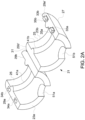
- FIG 2b shows schematically a connection clamping device 61 according to another embodiment of the invention in an open position.
- the difference from the connection clamping device 21 shown in Figure 2a is only that there is no hinge connecting the two halves 23a, 23b.
- Most of the reference numbers are the same as in Figure 2a and the description will not be repeated.
- a hinge connecting the two second connection surfaces 29b, 29b' a snap locking mechanism corresponding to the snap locking mechanism on the first connection surfaces 29a, 29a' is provided also to the second connection surfaces 29b, 29b'.
- Figure 4 shows the connection clamping device 21, 61 of Figure 2a or 2b in closed position over a flexible tube 1 and a connection means 5 of a port 3 hereby connecting the flexible tube to the port.
- the indicator window 51a or 51b that the flexible tube 1 is in correct position.
- the outer surface of the connection clamping device 21, 61 is smooth and will not damage any other components in the vicinity.
- Figure 6a shows schematically a connection clamping device 81 according to a non-claimed embodiment in an open position. Almost all the details are exactly the same as in the embodiment shown in Figure 2a so the reference numbers will be the same and the description will not be repeated. The difference is that in this embodiment a second rib 83a, 83b is provided in addition to the first rib 41a, 41b. This second rib 83a, 83b is provided in the end of the first and second halves 23a, 23b and is arranged to squeeze the tube against the connection means 5 just above the barb 9. This can be seen in Figure 6b .
- Figure 6b shows schematically the connection clamping device 81 of the embodiment of Figure 6a in connected position and in cross section.
- the first rib 41a, 41b is shown to squeeze the flexible tube 1 against the connection means 5 of the port 3 below the barb 9 and the second rib 83a, 83b is shown to squeeze the flexible tube 1 against the connection means 5 of the port 3 above the barb 9.
- this embodiment seals in a location (the cone area) that doesn't need to have mold insert lines. This makes the seal more reliable.
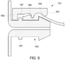
- this embodiment can include a feature that aligns the connection clamping device with the connection means in the axial direction. This feature is further shown and described in relation to Figure 9 . This feature will ensure that the second rib will seal against the coned surface of the barb.
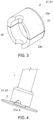
- FIG 8 shows schematically another embodiment of a connection clamping device 131 according to the invention.
- a different type of locking mechanism is provided instead of the latches and recesses described in relation to Figures 2a and 2b .
- the locking mechanism is a resilient sleeve 133 to be slid over the two halves when connected over the tube and connection means.
- it is shown to be two separate halves but they could also be hinged to each other.
- the outer surface of the two halves could be provided with a means, such as a recess or a pattern for receiving such a sleeve.
- the positioning rib 163 and the connection means rib 157 will when the connection clamping device is provided be adjacent each other and assure the position of the connection clamping device.
- the positioning rib 163 does not need to be a rib over the whole circumference. It can instead be for example two or more rib parts provided one in each half of the connection clamping device.
- An advantage with this embodiment is that the second rib of the connection clamping device can be assured to be provided sealing against the cone part of the barb. It could be suitably to seal against the cone part of the barb because this part may not comprise any mold insert lines.
Landscapes
- Engineering & Computer Science (AREA)
- General Engineering & Computer Science (AREA)
- Health & Medical Sciences (AREA)
- Heart & Thoracic Surgery (AREA)
- Mechanical Engineering (AREA)
- Hematology (AREA)
- Anesthesiology (AREA)
- Biomedical Technology (AREA)
- Pulmonology (AREA)
- Life Sciences & Earth Sciences (AREA)
- Animal Behavior & Ethology (AREA)
- General Health & Medical Sciences (AREA)
- Public Health (AREA)
- Veterinary Medicine (AREA)
- Infusion, Injection, And Reservoir Apparatuses (AREA)
- Quick-Acting Or Multi-Walled Pipe Joints (AREA)
- Joints That Cut Off Fluids, And Hose Joints (AREA)
Applications Claiming Priority (2)
| Application Number | Priority Date | Filing Date | Title |
|---|---|---|---|
| US201562237939P | 2015-10-06 | 2015-10-06 | |
| PCT/EP2016/073545 WO2017060188A1 (en) | 2015-10-06 | 2016-10-03 | Connection clamping device |
Publications (3)
| Publication Number | Publication Date |
|---|---|
| EP3359861A1 EP3359861A1 (en) | 2018-08-15 |
| EP3359861B1 EP3359861B1 (en) | 2020-11-25 |
| EP3359861B2 true EP3359861B2 (en) | 2023-12-13 |
Family
ID=57133142
Family Applications (1)
| Application Number | Title | Priority Date | Filing Date |
|---|---|---|---|
| EP16781316.1A Active EP3359861B2 (en) | 2015-10-06 | 2016-10-03 | Connection clamping device |
Country Status (5)
| Country | Link |
|---|---|
| US (1) | US11441713B2 (ja) |
| EP (1) | EP3359861B2 (ja) |
| JP (1) | JP7043111B2 (ja) |
| CN (1) | CN108139002B (ja) |
| WO (1) | WO2017060188A1 (ja) |
Families Citing this family (5)
| Publication number | Priority date | Publication date | Assignee | Title |
|---|---|---|---|---|
| DE102014102247B4 (de) * | 2014-02-21 | 2017-08-03 | Lemken Gmbh & Co. Kg | Schlauchstecksystem einer landwirtschaftlichen Verteilmaschine |
| WO2017060188A1 (en) | 2015-10-06 | 2017-04-13 | Ge Healthcare Bio-Sciences Corp. | Connection clamping device |
| EP3607233B1 (en) | 2017-04-05 | 2024-03-13 | Global Life Sciences Solutions USA LLC | Connection clamping device |
| WO2022146875A1 (en) * | 2020-12-29 | 2022-07-07 | Children's National Medical Center | Connection protector, securement system having the connection protector and uses thereof |
| EP4281161A1 (en) * | 2021-01-29 | 2023-11-29 | Alcyone Therapeutics, Inc. | Fixation devices for catheters |
Citations (14)
| Publication number | Priority date | Publication date | Assignee | Title |
|---|---|---|---|---|
| US3526416A (en) † | 1968-12-06 | 1970-09-01 | Murray Corp | Push-on fitting for use with nylon or rubber hoses |
| FR2478781A1 (fr) † | 1980-03-19 | 1981-09-25 | Rasmussen Gmbh | Dispositif de fixation d'un tube souple sur un manchon |
| DE3520953C1 (de) † | 1985-06-12 | 1986-09-18 | Karl Dipl.-Ing.(FH) 4040 Neuss Weinhold | Federbandschelle |
| EP0425770A2 (de) † | 1989-10-30 | 1991-05-08 | Weinhold, Karl Dipl.-Ing. (FH) | Vorrichtung zum Verbinden eines Schlauchendes mit einem Anschlussstutzen |
| US5137309A (en) † | 1991-06-26 | 1992-08-11 | Dana Corporation | Hose coupling insert |
| US6155610A (en) † | 1998-03-27 | 2000-12-05 | Hutchinson | Snap-fastenable coupling for a fluid-transfer hose |
| JP2006097841A (ja) † | 2004-09-30 | 2006-04-13 | Honda Motor Co Ltd | 配管継手構造 |
| US20060106365A1 (en) † | 2004-11-16 | 2006-05-18 | Welch Allyn, Inc. | Probe cover for thermometry apparatus |
| US7370889B2 (en) † | 2004-02-05 | 2008-05-13 | Bio Pure Technology Limited | Tube connector |
| US20080221469A1 (en) † | 2007-03-08 | 2008-09-11 | George John Shevchuk | Fitting and fluid-conveying device connected thereto |
| US20110163533A1 (en) † | 2009-12-31 | 2011-07-07 | Saint-Gobain Performance Plastics Corporation | System, method and apparatus for tubing connector |
| US8888140B2 (en) † | 2009-02-18 | 2014-11-18 | Parker-Hannifin Corporation | Hose fitting |
| WO2015066828A1 (es) † | 2013-11-08 | 2015-05-14 | Thc Chile S.A. | Sistema de conexión para conectar una tubería pex con un fitting que incluye una abrazadera |
| US20150167874A1 (en) † | 2012-06-20 | 2015-06-18 | Georg Fischer Jrg Ag | Clamping joint for pipes |
Family Cites Families (18)
| Publication number | Priority date | Publication date | Assignee | Title |
|---|---|---|---|---|
| GB968973A (en) * | 1962-11-05 | 1964-09-09 | Anchor Coupling Co Inc | Pressed-on coupling |
| US3185500A (en) | 1962-11-05 | 1965-05-25 | Anchor Coupling Company Inc | Pressed-on tube coupling having disassembly means |
| US4723948A (en) * | 1986-11-12 | 1988-02-09 | Pharmacia Nu Tech | Catheter attachment system |
| CN1014264B (zh) * | 1988-03-17 | 1991-10-09 | 马克斯·帕斯布里希 | 可拆式管棒联接器 |
| US4912602A (en) | 1988-11-04 | 1990-03-27 | Motorola, Inc. | Mechanical fastening system for an electronic equipment housing |
| IT233462Y1 (it) * | 1994-06-02 | 2000-01-28 | Hydrofit Spa | Raccordo tubolare a dado girevole perfezionato, particolarmente per tubi flessibili oleodinamici e simili |
| US6463632B2 (en) * | 2001-02-07 | 2002-10-15 | Hans Oetiker Ag Maschinen-Und Apparatefabrik | Guide arrangement for tightening tool emplacement in hose clamps provided with plastically deformable ears |
| JP2006038092A (ja) * | 2004-07-27 | 2006-02-09 | Togo Seisakusho Corp | ホースクランプ |
| NL1029408C2 (nl) | 2005-07-01 | 2007-01-04 | Wavin Bv | Buiskoppeling. |
| WO2008157710A1 (en) | 2007-06-19 | 2008-12-24 | Medical Components, Inc. | Catheter-to-device locking system |
| CN201547439U (zh) * | 2009-10-12 | 2010-08-11 | 梁广仁 | 软管连接装置 |
| CA2845635C (en) | 2011-09-06 | 2016-06-07 | Hemosphere, Inc. | Vascular access system with connector |
| EP2831481A4 (en) | 2012-03-27 | 2015-12-02 | Ags I Prop Llc | DEVICE FOR CONNECTING TUBES |
| FR3007813B1 (fr) | 2013-06-28 | 2016-01-01 | Sartorius Stedim Biotech | Connecteur fluidique avec collier et protection. |
| US10203058B2 (en) | 2014-04-24 | 2019-02-12 | Nordson Corporation | Reverse barb fluid connector and method of fluid connection |
| US20150362109A1 (en) | 2014-06-12 | 2015-12-17 | Buchanan Consulting LLC | Tube fitting connection system and method |
| CN104482307B (zh) * | 2014-12-18 | 2017-07-28 | 安徽江淮汽车集团股份有限公司 | 一种汽车管路的固定装置以及汽车 |
| WO2017060188A1 (en) | 2015-10-06 | 2017-04-13 | Ge Healthcare Bio-Sciences Corp. | Connection clamping device |
-
2016
- 2016-10-03 WO PCT/EP2016/073545 patent/WO2017060188A1/en active Application Filing
- 2016-10-03 CN CN201680058469.8A patent/CN108139002B/zh active Active
- 2016-10-03 EP EP16781316.1A patent/EP3359861B2/en active Active
- 2016-10-03 JP JP2018517403A patent/JP7043111B2/ja active Active
- 2016-10-03 US US15/759,973 patent/US11441713B2/en active Active
Patent Citations (15)
| Publication number | Priority date | Publication date | Assignee | Title |
|---|---|---|---|---|
| US3526416A (en) † | 1968-12-06 | 1970-09-01 | Murray Corp | Push-on fitting for use with nylon or rubber hoses |
| FR2478781A1 (fr) † | 1980-03-19 | 1981-09-25 | Rasmussen Gmbh | Dispositif de fixation d'un tube souple sur un manchon |
| DE3520953C1 (de) † | 1985-06-12 | 1986-09-18 | Karl Dipl.-Ing.(FH) 4040 Neuss Weinhold | Federbandschelle |
| EP0425770A2 (de) † | 1989-10-30 | 1991-05-08 | Weinhold, Karl Dipl.-Ing. (FH) | Vorrichtung zum Verbinden eines Schlauchendes mit einem Anschlussstutzen |
| US5137309A (en) † | 1991-06-26 | 1992-08-11 | Dana Corporation | Hose coupling insert |
| US6155610A (en) † | 1998-03-27 | 2000-12-05 | Hutchinson | Snap-fastenable coupling for a fluid-transfer hose |
| US7370889B2 (en) † | 2004-02-05 | 2008-05-13 | Bio Pure Technology Limited | Tube connector |
| JP2006097841A (ja) † | 2004-09-30 | 2006-04-13 | Honda Motor Co Ltd | 配管継手構造 |
| US20060106365A1 (en) † | 2004-11-16 | 2006-05-18 | Welch Allyn, Inc. | Probe cover for thermometry apparatus |
| US20080221469A1 (en) † | 2007-03-08 | 2008-09-11 | George John Shevchuk | Fitting and fluid-conveying device connected thereto |
| US8888140B2 (en) † | 2009-02-18 | 2014-11-18 | Parker-Hannifin Corporation | Hose fitting |
| US20110163533A1 (en) † | 2009-12-31 | 2011-07-07 | Saint-Gobain Performance Plastics Corporation | System, method and apparatus for tubing connector |
| US20150167874A1 (en) † | 2012-06-20 | 2015-06-18 | Georg Fischer Jrg Ag | Clamping joint for pipes |
| WO2015066828A1 (es) † | 2013-11-08 | 2015-05-14 | Thc Chile S.A. | Sistema de conexión para conectar una tubería pex con un fitting que incluye una abrazadera |
| EP3067611A1 (en) † | 2013-11-08 | 2016-09-14 | THC Chile S.A. | Connection system for connecting pex tubing to a fitting which includes a clamp |
Non-Patent Citations (2)
| Title |
|---|
| D6 traduction - écart bubbling + rib de position † |
| English translation of JP 2006097841 A † |
Also Published As
| Publication number | Publication date |
|---|---|
| JP2018535721A (ja) | 2018-12-06 |
| EP3359861A1 (en) | 2018-08-15 |
| EP3359861B1 (en) | 2020-11-25 |
| CN108139002A (zh) | 2018-06-08 |
| US20180266600A1 (en) | 2018-09-20 |
| US11441713B2 (en) | 2022-09-13 |
| JP7043111B2 (ja) | 2022-03-29 |
| WO2017060188A1 (en) | 2017-04-13 |
| CN108139002B (zh) | 2021-08-03 |
Similar Documents
| Publication | Publication Date | Title |
|---|---|---|
| EP3359861B2 (en) | Connection clamping device | |
| CN105042240B (zh) | 无性连接器以及流体连接的方法 | |
| US11221091B2 (en) | Sterile port connection | |
| US9279526B2 (en) | Apparatuses and methods for providing finger-tightened and ratchet-secured connections between conduits | |
| US11759617B2 (en) | Connection clamping device | |
| US20190264843A1 (en) | Pipe coupling | |
| CN106641538B (zh) | 非终止双封闭配件 | |
| WO2019187867A1 (ja) | ガスケット、及び流路継手構造 | |
| CN203757253U (zh) | 真空脱气设备的进气快速接头 | |
| US20140151998A1 (en) | Field Testable Instrument Housing Connection | |
| US10022492B2 (en) | Safety medical connector | |
| CN204345133U (zh) | 一种带截止阀的快换接头 | |
| EP3306165B1 (en) | Threaded retainer | |
| KR101532741B1 (ko) | 기밀 및 수밀 탐지기능이 구비된 접속관 | |
| CN214662666U (zh) | 一种管道软连接装置 | |
| EP2962723A1 (en) | Medical tube, method for manufacturing same, and tube connector | |
| US20220275892A1 (en) | Connector for flexible tubing | |
| CN211553531U (zh) | 一种卡环式胶管总成耐压试验检测密封连接装置 | |
| IL301148B2 (en) | the author of the bride | |
| US10016557B2 (en) | Safety medical connector | |
| KR20170052891A (ko) | 배관 커플러 | |
| WO2014153184A1 (en) | Apparatuses and methods for providing finger-tightened and ratchet-secured connections between conduits | |
| KR20180037361A (ko) | 완전삽입 확인이 용이한 산업용 멀티 레이어 유체배관 클림핑 연결시스템의 플라스틱 이음구조체 시공방법 |
Legal Events
| Date | Code | Title | Description |
|---|---|---|---|
| STAA | Information on the status of an ep patent application or granted ep patent |
Free format text: STATUS: THE INTERNATIONAL PUBLICATION HAS BEEN MADE |
|
| PUAI | Public reference made under article 153(3) epc to a published international application that has entered the european phase |
Free format text: ORIGINAL CODE: 0009012 |
|
| STAA | Information on the status of an ep patent application or granted ep patent |
Free format text: STATUS: REQUEST FOR EXAMINATION WAS MADE |
|
| 17P | Request for examination filed |
Effective date: 20180313 |
|
| AK | Designated contracting states |
Kind code of ref document: A1 Designated state(s): AL AT BE BG CH CY CZ DE DK EE ES FI FR GB GR HR HU IE IS IT LI LT LU LV MC MK MT NL NO PL PT RO RS SE SI SK SM TR |
|
| AX | Request for extension of the european patent |
Extension state: BA ME |
|
| DAV | Request for validation of the european patent (deleted) | ||
| DAX | Request for extension of the european patent (deleted) | ||
| STAA | Information on the status of an ep patent application or granted ep patent |
Free format text: STATUS: EXAMINATION IS IN PROGRESS |
|
| 17Q | First examination report despatched |
Effective date: 20191104 |
|
| RAP1 | Party data changed (applicant data changed or rights of an application transferred) |
Owner name: GLOBAL LIFE SCIENCES SOLUTIONS USA LLC |
|
| GRAP | Despatch of communication of intention to grant a patent |
Free format text: ORIGINAL CODE: EPIDOSNIGR1 |
|
| STAA | Information on the status of an ep patent application or granted ep patent |
Free format text: STATUS: GRANT OF PATENT IS INTENDED |
|
| TPAC | Observations filed by third parties |
Free format text: ORIGINAL CODE: EPIDOSNTIPA |
|
| INTG | Intention to grant announced |
Effective date: 20200710 |
|
| GRAS | Grant fee paid |
Free format text: ORIGINAL CODE: EPIDOSNIGR3 |
|
| GRAA | (expected) grant |
Free format text: ORIGINAL CODE: 0009210 |
|
| STAA | Information on the status of an ep patent application or granted ep patent |
Free format text: STATUS: THE PATENT HAS BEEN GRANTED |
|
| AK | Designated contracting states |
Kind code of ref document: B1 Designated state(s): AL AT BE BG CH CY CZ DE DK EE ES FI FR GB GR HR HU IE IS IT LI LT LU LV MC MK MT NL NO PL PT RO RS SE SI SK SM TR |
|
| REG | Reference to a national code |
Ref country code: GB Ref legal event code: FG4D |
|
| REG | Reference to a national code |
Ref country code: CH Ref legal event code: EP |
|
| REG | Reference to a national code |
Ref country code: AT Ref legal event code: REF Ref document number: 1338737 Country of ref document: AT Kind code of ref document: T Effective date: 20201215 |
|
| REG | Reference to a national code |
Ref country code: DE Ref legal event code: R096 Ref document number: 602016048640 Country of ref document: DE |
|
| REG | Reference to a national code |
Ref country code: IE Ref legal event code: FG4D |
|
| REG | Reference to a national code |
Ref country code: NL Ref legal event code: FP |
|
| REG | Reference to a national code |
Ref country code: AT Ref legal event code: MK05 Ref document number: 1338737 Country of ref document: AT Kind code of ref document: T Effective date: 20201125 |
|
| PG25 | Lapsed in a contracting state [announced via postgrant information from national office to epo] |
Ref country code: GR Free format text: LAPSE BECAUSE OF FAILURE TO SUBMIT A TRANSLATION OF THE DESCRIPTION OR TO PAY THE FEE WITHIN THE PRESCRIBED TIME-LIMIT Effective date: 20210226 Ref country code: FI Free format text: LAPSE BECAUSE OF FAILURE TO SUBMIT A TRANSLATION OF THE DESCRIPTION OR TO PAY THE FEE WITHIN THE PRESCRIBED TIME-LIMIT Effective date: 20201125 Ref country code: NO Free format text: LAPSE BECAUSE OF FAILURE TO SUBMIT A TRANSLATION OF THE DESCRIPTION OR TO PAY THE FEE WITHIN THE PRESCRIBED TIME-LIMIT Effective date: 20210225 Ref country code: RS Free format text: LAPSE BECAUSE OF FAILURE TO SUBMIT A TRANSLATION OF THE DESCRIPTION OR TO PAY THE FEE WITHIN THE PRESCRIBED TIME-LIMIT Effective date: 20201125 Ref country code: PT Free format text: LAPSE BECAUSE OF FAILURE TO SUBMIT A TRANSLATION OF THE DESCRIPTION OR TO PAY THE FEE WITHIN THE PRESCRIBED TIME-LIMIT Effective date: 20210325 |
|
| PG25 | Lapsed in a contracting state [announced via postgrant information from national office to epo] |
Ref country code: BG Free format text: LAPSE BECAUSE OF FAILURE TO SUBMIT A TRANSLATION OF THE DESCRIPTION OR TO PAY THE FEE WITHIN THE PRESCRIBED TIME-LIMIT Effective date: 20210225 Ref country code: LV Free format text: LAPSE BECAUSE OF FAILURE TO SUBMIT A TRANSLATION OF THE DESCRIPTION OR TO PAY THE FEE WITHIN THE PRESCRIBED TIME-LIMIT Effective date: 20201125 Ref country code: PL Free format text: LAPSE BECAUSE OF FAILURE TO SUBMIT A TRANSLATION OF THE DESCRIPTION OR TO PAY THE FEE WITHIN THE PRESCRIBED TIME-LIMIT Effective date: 20201125 Ref country code: IS Free format text: LAPSE BECAUSE OF FAILURE TO SUBMIT A TRANSLATION OF THE DESCRIPTION OR TO PAY THE FEE WITHIN THE PRESCRIBED TIME-LIMIT Effective date: 20210325 Ref country code: AT Free format text: LAPSE BECAUSE OF FAILURE TO SUBMIT A TRANSLATION OF THE DESCRIPTION OR TO PAY THE FEE WITHIN THE PRESCRIBED TIME-LIMIT Effective date: 20201125 Ref country code: SE Free format text: LAPSE BECAUSE OF FAILURE TO SUBMIT A TRANSLATION OF THE DESCRIPTION OR TO PAY THE FEE WITHIN THE PRESCRIBED TIME-LIMIT Effective date: 20201125 |
|
| REG | Reference to a national code |
Ref country code: LT Ref legal event code: MG9D |
|
| PG25 | Lapsed in a contracting state [announced via postgrant information from national office to epo] |
Ref country code: HR Free format text: LAPSE BECAUSE OF FAILURE TO SUBMIT A TRANSLATION OF THE DESCRIPTION OR TO PAY THE FEE WITHIN THE PRESCRIBED TIME-LIMIT Effective date: 20201125 |
|
| PG25 | Lapsed in a contracting state [announced via postgrant information from national office to epo] |
Ref country code: CZ Free format text: LAPSE BECAUSE OF FAILURE TO SUBMIT A TRANSLATION OF THE DESCRIPTION OR TO PAY THE FEE WITHIN THE PRESCRIBED TIME-LIMIT Effective date: 20201125 Ref country code: EE Free format text: LAPSE BECAUSE OF FAILURE TO SUBMIT A TRANSLATION OF THE DESCRIPTION OR TO PAY THE FEE WITHIN THE PRESCRIBED TIME-LIMIT Effective date: 20201125 Ref country code: SM Free format text: LAPSE BECAUSE OF FAILURE TO SUBMIT A TRANSLATION OF THE DESCRIPTION OR TO PAY THE FEE WITHIN THE PRESCRIBED TIME-LIMIT Effective date: 20201125 Ref country code: LT Free format text: LAPSE BECAUSE OF FAILURE TO SUBMIT A TRANSLATION OF THE DESCRIPTION OR TO PAY THE FEE WITHIN THE PRESCRIBED TIME-LIMIT Effective date: 20201125 Ref country code: SK Free format text: LAPSE BECAUSE OF FAILURE TO SUBMIT A TRANSLATION OF THE DESCRIPTION OR TO PAY THE FEE WITHIN THE PRESCRIBED TIME-LIMIT Effective date: 20201125 Ref country code: RO Free format text: LAPSE BECAUSE OF FAILURE TO SUBMIT A TRANSLATION OF THE DESCRIPTION OR TO PAY THE FEE WITHIN THE PRESCRIBED TIME-LIMIT Effective date: 20201125 |
|
| REG | Reference to a national code |
Ref country code: DE Ref legal event code: R026 Ref document number: 602016048640 Country of ref document: DE |
|
| PLBI | Opposition filed |
Free format text: ORIGINAL CODE: 0009260 |
|
| PG25 | Lapsed in a contracting state [announced via postgrant information from national office to epo] |
Ref country code: DK Free format text: LAPSE BECAUSE OF FAILURE TO SUBMIT A TRANSLATION OF THE DESCRIPTION OR TO PAY THE FEE WITHIN THE PRESCRIBED TIME-LIMIT Effective date: 20201125 |
|
| PLAX | Notice of opposition and request to file observation + time limit sent |
Free format text: ORIGINAL CODE: EPIDOSNOBS2 |
|
| 26 | Opposition filed |
Opponent name: SARTORIUS STEDIM FMT SAS Effective date: 20210825 |
|
| PG25 | Lapsed in a contracting state [announced via postgrant information from national office to epo] |
Ref country code: AL Free format text: LAPSE BECAUSE OF FAILURE TO SUBMIT A TRANSLATION OF THE DESCRIPTION OR TO PAY THE FEE WITHIN THE PRESCRIBED TIME-LIMIT Effective date: 20201125 Ref country code: IT Free format text: LAPSE BECAUSE OF FAILURE TO SUBMIT A TRANSLATION OF THE DESCRIPTION OR TO PAY THE FEE WITHIN THE PRESCRIBED TIME-LIMIT Effective date: 20201125 |
|
| PG25 | Lapsed in a contracting state [announced via postgrant information from national office to epo] |
Ref country code: SI Free format text: LAPSE BECAUSE OF FAILURE TO SUBMIT A TRANSLATION OF THE DESCRIPTION OR TO PAY THE FEE WITHIN THE PRESCRIBED TIME-LIMIT Effective date: 20201125 |
|
| PLBB | Reply of patent proprietor to notice(s) of opposition received |
Free format text: ORIGINAL CODE: EPIDOSNOBS3 |
|
| PG25 | Lapsed in a contracting state [announced via postgrant information from national office to epo] |
Ref country code: ES Free format text: LAPSE BECAUSE OF FAILURE TO SUBMIT A TRANSLATION OF THE DESCRIPTION OR TO PAY THE FEE WITHIN THE PRESCRIBED TIME-LIMIT Effective date: 20201125 |
|
| REG | Reference to a national code |
Ref country code: CH Ref legal event code: PL |
|
| PG25 | Lapsed in a contracting state [announced via postgrant information from national office to epo] |
Ref country code: IS Free format text: LAPSE BECAUSE OF FAILURE TO SUBMIT A TRANSLATION OF THE DESCRIPTION OR TO PAY THE FEE WITHIN THE PRESCRIBED TIME-LIMIT Effective date: 20210325 |
|
| PG25 | Lapsed in a contracting state [announced via postgrant information from national office to epo] |
Ref country code: MC Free format text: LAPSE BECAUSE OF FAILURE TO SUBMIT A TRANSLATION OF THE DESCRIPTION OR TO PAY THE FEE WITHIN THE PRESCRIBED TIME-LIMIT Effective date: 20201125 |
|
| PG25 | Lapsed in a contracting state [announced via postgrant information from national office to epo] |
Ref country code: LU Free format text: LAPSE BECAUSE OF NON-PAYMENT OF DUE FEES Effective date: 20211003 |
|
| PG25 | Lapsed in a contracting state [announced via postgrant information from national office to epo] |
Ref country code: LI Free format text: LAPSE BECAUSE OF NON-PAYMENT OF DUE FEES Effective date: 20211031 Ref country code: CH Free format text: LAPSE BECAUSE OF NON-PAYMENT OF DUE FEES Effective date: 20211031 |
|
| PG25 | Lapsed in a contracting state [announced via postgrant information from national office to epo] |
Ref country code: IE Free format text: LAPSE BECAUSE OF NON-PAYMENT OF DUE FEES Effective date: 20211003 |
|
| PG25 | Lapsed in a contracting state [announced via postgrant information from national office to epo] |
Ref country code: HU Free format text: LAPSE BECAUSE OF FAILURE TO SUBMIT A TRANSLATION OF THE DESCRIPTION OR TO PAY THE FEE WITHIN THE PRESCRIBED TIME-LIMIT; INVALID AB INITIO Effective date: 20161003 |
|
| APBM | Appeal reference recorded |
Free format text: ORIGINAL CODE: EPIDOSNREFNO |
|
| APBP | Date of receipt of notice of appeal recorded |
Free format text: ORIGINAL CODE: EPIDOSNNOA2O |
|
| APAH | Appeal reference modified |
Free format text: ORIGINAL CODE: EPIDOSCREFNO |
|
| PG25 | Lapsed in a contracting state [announced via postgrant information from national office to epo] |
Ref country code: CY Free format text: LAPSE BECAUSE OF FAILURE TO SUBMIT A TRANSLATION OF THE DESCRIPTION OR TO PAY THE FEE WITHIN THE PRESCRIBED TIME-LIMIT Effective date: 20201125 |
|
| APBU | Appeal procedure closed |
Free format text: ORIGINAL CODE: EPIDOSNNOA9O |
|
| P01 | Opt-out of the competence of the unified patent court (upc) registered |
Effective date: 20230526 |
|
| PGFP | Annual fee paid to national office [announced via postgrant information from national office to epo] |
Ref country code: NL Payment date: 20230825 Year of fee payment: 8 |
|
| PGFP | Annual fee paid to national office [announced via postgrant information from national office to epo] |
Ref country code: GB Payment date: 20230817 Year of fee payment: 8 |
|
| PUAH | Patent maintained in amended form |
Free format text: ORIGINAL CODE: 0009272 |
|
| STAA | Information on the status of an ep patent application or granted ep patent |
Free format text: STATUS: PATENT MAINTAINED AS AMENDED |
|
| PGFP | Annual fee paid to national office [announced via postgrant information from national office to epo] |
Ref country code: FR Payment date: 20230821 Year of fee payment: 8 Ref country code: BE Payment date: 20230918 Year of fee payment: 8 |
|
| 27A | Patent maintained in amended form |
Effective date: 20231213 |
|
| AK | Designated contracting states |
Kind code of ref document: B2 Designated state(s): AL AT BE BG CH CY CZ DE DK EE ES FI FR GB GR HR HU IE IS IT LI LT LU LV MC MK MT NL NO PL PT RO RS SE SI SK SM TR |
|
| REG | Reference to a national code |
Ref country code: DE Ref legal event code: R102 Ref document number: 602016048640 Country of ref document: DE |
|
| PGFP | Annual fee paid to national office [announced via postgrant information from national office to epo] |
Ref country code: DE Payment date: 20230822 Year of fee payment: 8 |
|
| REG | Reference to a national code |
Ref country code: NL Ref legal event code: FP |
|
| PG25 | Lapsed in a contracting state [announced via postgrant information from national office to epo] |
Ref country code: MK Free format text: LAPSE BECAUSE OF FAILURE TO SUBMIT A TRANSLATION OF THE DESCRIPTION OR TO PAY THE FEE WITHIN THE PRESCRIBED TIME-LIMIT Effective date: 20201125 |