EP3358239A1 - Boil-off gas recovery system - Google Patents
Boil-off gas recovery system Download PDFInfo
- Publication number
- EP3358239A1 EP3358239A1 EP17207990.7A EP17207990A EP3358239A1 EP 3358239 A1 EP3358239 A1 EP 3358239A1 EP 17207990 A EP17207990 A EP 17207990A EP 3358239 A1 EP3358239 A1 EP 3358239A1
- Authority
- EP
- European Patent Office
- Prior art keywords
- gas
- boil
- lubricating oil
- activated carbon
- recovery system
- Prior art date
- Legal status (The legal status is an assumption and is not a legal conclusion. Google has not performed a legal analysis and makes no representation as to the accuracy of the status listed.)
- Granted
Links
- 238000011084 recovery Methods 0.000 title claims abstract description 63
- OKTJSMMVPCPJKN-UHFFFAOYSA-N Carbon Chemical compound [C] OKTJSMMVPCPJKN-UHFFFAOYSA-N 0.000 claims abstract description 176
- 239000010687 lubricating oil Substances 0.000 claims abstract description 85
- 238000009834 vaporization Methods 0.000 claims abstract description 6
- 230000008016 vaporization Effects 0.000 claims abstract description 6
- 239000003921 oil Substances 0.000 claims description 42
- 238000000926 separation method Methods 0.000 claims description 32
- 239000007788 liquid Substances 0.000 claims description 31
- 238000010521 absorption reaction Methods 0.000 claims description 22
- 238000012544 monitoring process Methods 0.000 claims description 7
- 230000006866 deterioration Effects 0.000 abstract description 6
- 239000007789 gas Substances 0.000 description 226
- 238000010586 diagram Methods 0.000 description 13
- 238000002485 combustion reaction Methods 0.000 description 9
- 230000006835 compression Effects 0.000 description 9
- 238000007906 compression Methods 0.000 description 9
- 238000011144 upstream manufacturing Methods 0.000 description 8
- 239000003949 liquefied natural gas Substances 0.000 description 6
- 239000003595 mist Substances 0.000 description 5
- 238000001514 detection method Methods 0.000 description 4
- 238000012423 maintenance Methods 0.000 description 4
- 239000002245 particle Substances 0.000 description 4
- 238000001816 cooling Methods 0.000 description 3
- 239000000446 fuel Substances 0.000 description 3
- 238000000034 method Methods 0.000 description 2
- 238000001556 precipitation Methods 0.000 description 2
- 229910021536 Zeolite Inorganic materials 0.000 description 1
- 230000008859 change Effects 0.000 description 1
- 239000000470 constituent Substances 0.000 description 1
- HNPSIPDUKPIQMN-UHFFFAOYSA-N dioxosilane;oxo(oxoalumanyloxy)alumane Chemical compound O=[Si]=O.O=[Al]O[Al]=O HNPSIPDUKPIQMN-UHFFFAOYSA-N 0.000 description 1
- 230000000694 effects Effects 0.000 description 1
- 239000003915 liquefied petroleum gas Substances 0.000 description 1
- 238000012986 modification Methods 0.000 description 1
- 230000004048 modification Effects 0.000 description 1
- 239000011148 porous material Substances 0.000 description 1
- 238000010248 power generation Methods 0.000 description 1
- 230000008569 process Effects 0.000 description 1
- 239000013535 sea water Substances 0.000 description 1
- 230000032258 transport Effects 0.000 description 1
- 239000010457 zeolite Substances 0.000 description 1
Images


Classifications
-
- F—MECHANICAL ENGINEERING; LIGHTING; HEATING; WEAPONS; BLASTING
- F17—STORING OR DISTRIBUTING GASES OR LIQUIDS
- F17C—VESSELS FOR CONTAINING OR STORING COMPRESSED, LIQUEFIED OR SOLIDIFIED GASES; FIXED-CAPACITY GAS-HOLDERS; FILLING VESSELS WITH, OR DISCHARGING FROM VESSELS, COMPRESSED, LIQUEFIED, OR SOLIDIFIED GASES
- F17C5/00—Methods or apparatus for filling containers with liquefied, solidified, or compressed gases under pressures
- F17C5/02—Methods or apparatus for filling containers with liquefied, solidified, or compressed gases under pressures for filling with liquefied gases
-
- F—MECHANICAL ENGINEERING; LIGHTING; HEATING; WEAPONS; BLASTING
- F17—STORING OR DISTRIBUTING GASES OR LIQUIDS
- F17C—VESSELS FOR CONTAINING OR STORING COMPRESSED, LIQUEFIED OR SOLIDIFIED GASES; FIXED-CAPACITY GAS-HOLDERS; FILLING VESSELS WITH, OR DISCHARGING FROM VESSELS, COMPRESSED, LIQUEFIED, OR SOLIDIFIED GASES
- F17C9/00—Methods or apparatus for discharging liquefied or solidified gases from vessels not under pressure
-
- B—PERFORMING OPERATIONS; TRANSPORTING
- B63—SHIPS OR OTHER WATERBORNE VESSELS; RELATED EQUIPMENT
- B63B—SHIPS OR OTHER WATERBORNE VESSELS; EQUIPMENT FOR SHIPPING
- B63B25/00—Load-accommodating arrangements, e.g. stowing, trimming; Vessels characterised thereby
- B63B25/02—Load-accommodating arrangements, e.g. stowing, trimming; Vessels characterised thereby for bulk goods
- B63B25/08—Load-accommodating arrangements, e.g. stowing, trimming; Vessels characterised thereby for bulk goods fluid
- B63B25/12—Load-accommodating arrangements, e.g. stowing, trimming; Vessels characterised thereby for bulk goods fluid closed
- B63B25/16—Load-accommodating arrangements, e.g. stowing, trimming; Vessels characterised thereby for bulk goods fluid closed heat-insulated
-
- F—MECHANICAL ENGINEERING; LIGHTING; HEATING; WEAPONS; BLASTING
- F17—STORING OR DISTRIBUTING GASES OR LIQUIDS
- F17C—VESSELS FOR CONTAINING OR STORING COMPRESSED, LIQUEFIED OR SOLIDIFIED GASES; FIXED-CAPACITY GAS-HOLDERS; FILLING VESSELS WITH, OR DISCHARGING FROM VESSELS, COMPRESSED, LIQUEFIED, OR SOLIDIFIED GASES
- F17C1/00—Pressure vessels, e.g. gas cylinder, gas tank, replaceable cartridge
-
- F—MECHANICAL ENGINEERING; LIGHTING; HEATING; WEAPONS; BLASTING
- F17—STORING OR DISTRIBUTING GASES OR LIQUIDS
- F17C—VESSELS FOR CONTAINING OR STORING COMPRESSED, LIQUEFIED OR SOLIDIFIED GASES; FIXED-CAPACITY GAS-HOLDERS; FILLING VESSELS WITH, OR DISCHARGING FROM VESSELS, COMPRESSED, LIQUEFIED, OR SOLIDIFIED GASES
- F17C13/00—Details of vessels or of the filling or discharging of vessels
- F17C13/002—Details of vessels or of the filling or discharging of vessels for vessels under pressure
-
- F—MECHANICAL ENGINEERING; LIGHTING; HEATING; WEAPONS; BLASTING
- F17—STORING OR DISTRIBUTING GASES OR LIQUIDS
- F17C—VESSELS FOR CONTAINING OR STORING COMPRESSED, LIQUEFIED OR SOLIDIFIED GASES; FIXED-CAPACITY GAS-HOLDERS; FILLING VESSELS WITH, OR DISCHARGING FROM VESSELS, COMPRESSED, LIQUEFIED, OR SOLIDIFIED GASES
- F17C13/00—Details of vessels or of the filling or discharging of vessels
- F17C13/02—Special adaptations of indicating, measuring, or monitoring equipment
- F17C13/025—Special adaptations of indicating, measuring, or monitoring equipment having the pressure as the parameter
-
- F—MECHANICAL ENGINEERING; LIGHTING; HEATING; WEAPONS; BLASTING
- F17—STORING OR DISTRIBUTING GASES OR LIQUIDS
- F17C—VESSELS FOR CONTAINING OR STORING COMPRESSED, LIQUEFIED OR SOLIDIFIED GASES; FIXED-CAPACITY GAS-HOLDERS; FILLING VESSELS WITH, OR DISCHARGING FROM VESSELS, COMPRESSED, LIQUEFIED, OR SOLIDIFIED GASES
- F17C5/00—Methods or apparatus for filling containers with liquefied, solidified, or compressed gases under pressures
- F17C5/06—Methods or apparatus for filling containers with liquefied, solidified, or compressed gases under pressures for filling with compressed gases
-
- F—MECHANICAL ENGINEERING; LIGHTING; HEATING; WEAPONS; BLASTING
- F17—STORING OR DISTRIBUTING GASES OR LIQUIDS
- F17C—VESSELS FOR CONTAINING OR STORING COMPRESSED, LIQUEFIED OR SOLIDIFIED GASES; FIXED-CAPACITY GAS-HOLDERS; FILLING VESSELS WITH, OR DISCHARGING FROM VESSELS, COMPRESSED, LIQUEFIED, OR SOLIDIFIED GASES
- F17C6/00—Methods and apparatus for filling vessels not under pressure with liquefied or solidified gases
-
- F—MECHANICAL ENGINEERING; LIGHTING; HEATING; WEAPONS; BLASTING
- F17—STORING OR DISTRIBUTING GASES OR LIQUIDS
- F17C—VESSELS FOR CONTAINING OR STORING COMPRESSED, LIQUEFIED OR SOLIDIFIED GASES; FIXED-CAPACITY GAS-HOLDERS; FILLING VESSELS WITH, OR DISCHARGING FROM VESSELS, COMPRESSED, LIQUEFIED, OR SOLIDIFIED GASES
- F17C2205/00—Vessel construction, in particular mounting arrangements, attachments or identifications means
- F17C2205/03—Fluid connections, filters, valves, closure means or other attachments
- F17C2205/0302—Fittings, valves, filters, or components in connection with the gas storage device
- F17C2205/0341—Filters
- F17C2205/0347—Active charcoal type
-
- F—MECHANICAL ENGINEERING; LIGHTING; HEATING; WEAPONS; BLASTING
- F17—STORING OR DISTRIBUTING GASES OR LIQUIDS
- F17C—VESSELS FOR CONTAINING OR STORING COMPRESSED, LIQUEFIED OR SOLIDIFIED GASES; FIXED-CAPACITY GAS-HOLDERS; FILLING VESSELS WITH, OR DISCHARGING FROM VESSELS, COMPRESSED, LIQUEFIED, OR SOLIDIFIED GASES
- F17C2221/00—Handled fluid, in particular type of fluid
- F17C2221/03—Mixtures
- F17C2221/032—Hydrocarbons
- F17C2221/033—Methane, e.g. natural gas, CNG, LNG, GNL, GNC, PLNG
-
- F—MECHANICAL ENGINEERING; LIGHTING; HEATING; WEAPONS; BLASTING
- F17—STORING OR DISTRIBUTING GASES OR LIQUIDS
- F17C—VESSELS FOR CONTAINING OR STORING COMPRESSED, LIQUEFIED OR SOLIDIFIED GASES; FIXED-CAPACITY GAS-HOLDERS; FILLING VESSELS WITH, OR DISCHARGING FROM VESSELS, COMPRESSED, LIQUEFIED, OR SOLIDIFIED GASES
- F17C2221/00—Handled fluid, in particular type of fluid
- F17C2221/03—Mixtures
- F17C2221/032—Hydrocarbons
- F17C2221/035—Propane butane, e.g. LPG, GPL
-
- F—MECHANICAL ENGINEERING; LIGHTING; HEATING; WEAPONS; BLASTING
- F17—STORING OR DISTRIBUTING GASES OR LIQUIDS
- F17C—VESSELS FOR CONTAINING OR STORING COMPRESSED, LIQUEFIED OR SOLIDIFIED GASES; FIXED-CAPACITY GAS-HOLDERS; FILLING VESSELS WITH, OR DISCHARGING FROM VESSELS, COMPRESSED, LIQUEFIED, OR SOLIDIFIED GASES
- F17C2223/00—Handled fluid before transfer, i.e. state of fluid when stored in the vessel or before transfer from the vessel
- F17C2223/01—Handled fluid before transfer, i.e. state of fluid when stored in the vessel or before transfer from the vessel characterised by the phase
- F17C2223/0146—Two-phase
- F17C2223/0153—Liquefied gas, e.g. LPG, GPL
- F17C2223/0161—Liquefied gas, e.g. LPG, GPL cryogenic, e.g. LNG, GNL, PLNG
-
- F—MECHANICAL ENGINEERING; LIGHTING; HEATING; WEAPONS; BLASTING
- F17—STORING OR DISTRIBUTING GASES OR LIQUIDS
- F17C—VESSELS FOR CONTAINING OR STORING COMPRESSED, LIQUEFIED OR SOLIDIFIED GASES; FIXED-CAPACITY GAS-HOLDERS; FILLING VESSELS WITH, OR DISCHARGING FROM VESSELS, COMPRESSED, LIQUEFIED, OR SOLIDIFIED GASES
- F17C2223/00—Handled fluid before transfer, i.e. state of fluid when stored in the vessel or before transfer from the vessel
- F17C2223/03—Handled fluid before transfer, i.e. state of fluid when stored in the vessel or before transfer from the vessel characterised by the pressure level
- F17C2223/033—Small pressure, e.g. for liquefied gas
-
- F—MECHANICAL ENGINEERING; LIGHTING; HEATING; WEAPONS; BLASTING
- F17—STORING OR DISTRIBUTING GASES OR LIQUIDS
- F17C—VESSELS FOR CONTAINING OR STORING COMPRESSED, LIQUEFIED OR SOLIDIFIED GASES; FIXED-CAPACITY GAS-HOLDERS; FILLING VESSELS WITH, OR DISCHARGING FROM VESSELS, COMPRESSED, LIQUEFIED, OR SOLIDIFIED GASES
- F17C2223/00—Handled fluid before transfer, i.e. state of fluid when stored in the vessel or before transfer from the vessel
- F17C2223/04—Handled fluid before transfer, i.e. state of fluid when stored in the vessel or before transfer from the vessel characterised by other properties of handled fluid before transfer
- F17C2223/042—Localisation of the removal point
- F17C2223/043—Localisation of the removal point in the gas
-
- F—MECHANICAL ENGINEERING; LIGHTING; HEATING; WEAPONS; BLASTING
- F17—STORING OR DISTRIBUTING GASES OR LIQUIDS
- F17C—VESSELS FOR CONTAINING OR STORING COMPRESSED, LIQUEFIED OR SOLIDIFIED GASES; FIXED-CAPACITY GAS-HOLDERS; FILLING VESSELS WITH, OR DISCHARGING FROM VESSELS, COMPRESSED, LIQUEFIED, OR SOLIDIFIED GASES
- F17C2227/00—Transfer of fluids, i.e. method or means for transferring the fluid; Heat exchange with the fluid
- F17C2227/01—Propulsion of the fluid
- F17C2227/0128—Propulsion of the fluid with pumps or compressors
- F17C2227/0157—Compressors
- F17C2227/0164—Compressors with specified compressor type, e.g. piston or impulsive type
-
- F—MECHANICAL ENGINEERING; LIGHTING; HEATING; WEAPONS; BLASTING
- F17—STORING OR DISTRIBUTING GASES OR LIQUIDS
- F17C—VESSELS FOR CONTAINING OR STORING COMPRESSED, LIQUEFIED OR SOLIDIFIED GASES; FIXED-CAPACITY GAS-HOLDERS; FILLING VESSELS WITH, OR DISCHARGING FROM VESSELS, COMPRESSED, LIQUEFIED, OR SOLIDIFIED GASES
- F17C2227/00—Transfer of fluids, i.e. method or means for transferring the fluid; Heat exchange with the fluid
- F17C2227/03—Heat exchange with the fluid
- F17C2227/0337—Heat exchange with the fluid by cooling
- F17C2227/0339—Heat exchange with the fluid by cooling using the same fluid
-
- F—MECHANICAL ENGINEERING; LIGHTING; HEATING; WEAPONS; BLASTING
- F17—STORING OR DISTRIBUTING GASES OR LIQUIDS
- F17C—VESSELS FOR CONTAINING OR STORING COMPRESSED, LIQUEFIED OR SOLIDIFIED GASES; FIXED-CAPACITY GAS-HOLDERS; FILLING VESSELS WITH, OR DISCHARGING FROM VESSELS, COMPRESSED, LIQUEFIED, OR SOLIDIFIED GASES
- F17C2250/00—Accessories; Control means; Indicating, measuring or monitoring of parameters
- F17C2250/03—Control means
- F17C2250/036—Control means using alarms
-
- F—MECHANICAL ENGINEERING; LIGHTING; HEATING; WEAPONS; BLASTING
- F17—STORING OR DISTRIBUTING GASES OR LIQUIDS
- F17C—VESSELS FOR CONTAINING OR STORING COMPRESSED, LIQUEFIED OR SOLIDIFIED GASES; FIXED-CAPACITY GAS-HOLDERS; FILLING VESSELS WITH, OR DISCHARGING FROM VESSELS, COMPRESSED, LIQUEFIED, OR SOLIDIFIED GASES
- F17C2250/00—Accessories; Control means; Indicating, measuring or monitoring of parameters
- F17C2250/04—Indicating or measuring of parameters as input values
- F17C2250/0404—Parameters indicated or measured
- F17C2250/0408—Level of content in the vessel
-
- F—MECHANICAL ENGINEERING; LIGHTING; HEATING; WEAPONS; BLASTING
- F17—STORING OR DISTRIBUTING GASES OR LIQUIDS
- F17C—VESSELS FOR CONTAINING OR STORING COMPRESSED, LIQUEFIED OR SOLIDIFIED GASES; FIXED-CAPACITY GAS-HOLDERS; FILLING VESSELS WITH, OR DISCHARGING FROM VESSELS, COMPRESSED, LIQUEFIED, OR SOLIDIFIED GASES
- F17C2250/00—Accessories; Control means; Indicating, measuring or monitoring of parameters
- F17C2250/04—Indicating or measuring of parameters as input values
- F17C2250/0404—Parameters indicated or measured
- F17C2250/043—Pressure
- F17C2250/0434—Pressure difference
-
- F—MECHANICAL ENGINEERING; LIGHTING; HEATING; WEAPONS; BLASTING
- F17—STORING OR DISTRIBUTING GASES OR LIQUIDS
- F17C—VESSELS FOR CONTAINING OR STORING COMPRESSED, LIQUEFIED OR SOLIDIFIED GASES; FIXED-CAPACITY GAS-HOLDERS; FILLING VESSELS WITH, OR DISCHARGING FROM VESSELS, COMPRESSED, LIQUEFIED, OR SOLIDIFIED GASES
- F17C2265/00—Effects achieved by gas storage or gas handling
- F17C2265/01—Purifying the fluid
- F17C2265/012—Purifying the fluid by filtering
-
- F—MECHANICAL ENGINEERING; LIGHTING; HEATING; WEAPONS; BLASTING
- F17—STORING OR DISTRIBUTING GASES OR LIQUIDS
- F17C—VESSELS FOR CONTAINING OR STORING COMPRESSED, LIQUEFIED OR SOLIDIFIED GASES; FIXED-CAPACITY GAS-HOLDERS; FILLING VESSELS WITH, OR DISCHARGING FROM VESSELS, COMPRESSED, LIQUEFIED, OR SOLIDIFIED GASES
- F17C2265/00—Effects achieved by gas storage or gas handling
- F17C2265/01—Purifying the fluid
- F17C2265/015—Purifying the fluid by separating
-
- F—MECHANICAL ENGINEERING; LIGHTING; HEATING; WEAPONS; BLASTING
- F17—STORING OR DISTRIBUTING GASES OR LIQUIDS
- F17C—VESSELS FOR CONTAINING OR STORING COMPRESSED, LIQUEFIED OR SOLIDIFIED GASES; FIXED-CAPACITY GAS-HOLDERS; FILLING VESSELS WITH, OR DISCHARGING FROM VESSELS, COMPRESSED, LIQUEFIED, OR SOLIDIFIED GASES
- F17C2265/00—Effects achieved by gas storage or gas handling
- F17C2265/03—Treating the boil-off
- F17C2265/032—Treating the boil-off by recovery
- F17C2265/033—Treating the boil-off by recovery with cooling
- F17C2265/034—Treating the boil-off by recovery with cooling with condensing the gas phase
-
- F—MECHANICAL ENGINEERING; LIGHTING; HEATING; WEAPONS; BLASTING
- F17—STORING OR DISTRIBUTING GASES OR LIQUIDS
- F17C—VESSELS FOR CONTAINING OR STORING COMPRESSED, LIQUEFIED OR SOLIDIFIED GASES; FIXED-CAPACITY GAS-HOLDERS; FILLING VESSELS WITH, OR DISCHARGING FROM VESSELS, COMPRESSED, LIQUEFIED, OR SOLIDIFIED GASES
- F17C2265/00—Effects achieved by gas storage or gas handling
- F17C2265/03—Treating the boil-off
- F17C2265/032—Treating the boil-off by recovery
- F17C2265/037—Treating the boil-off by recovery with pressurising
-
- F—MECHANICAL ENGINEERING; LIGHTING; HEATING; WEAPONS; BLASTING
- F17—STORING OR DISTRIBUTING GASES OR LIQUIDS
- F17C—VESSELS FOR CONTAINING OR STORING COMPRESSED, LIQUEFIED OR SOLIDIFIED GASES; FIXED-CAPACITY GAS-HOLDERS; FILLING VESSELS WITH, OR DISCHARGING FROM VESSELS, COMPRESSED, LIQUEFIED, OR SOLIDIFIED GASES
- F17C2265/00—Effects achieved by gas storage or gas handling
- F17C2265/06—Fluid distribution
- F17C2265/066—Fluid distribution for feeding engines for propulsion
-
- F—MECHANICAL ENGINEERING; LIGHTING; HEATING; WEAPONS; BLASTING
- F17—STORING OR DISTRIBUTING GASES OR LIQUIDS
- F17C—VESSELS FOR CONTAINING OR STORING COMPRESSED, LIQUEFIED OR SOLIDIFIED GASES; FIXED-CAPACITY GAS-HOLDERS; FILLING VESSELS WITH, OR DISCHARGING FROM VESSELS, COMPRESSED, LIQUEFIED, OR SOLIDIFIED GASES
- F17C2265/00—Effects achieved by gas storage or gas handling
- F17C2265/07—Generating electrical power as side effect
-
- F—MECHANICAL ENGINEERING; LIGHTING; HEATING; WEAPONS; BLASTING
- F17—STORING OR DISTRIBUTING GASES OR LIQUIDS
- F17C—VESSELS FOR CONTAINING OR STORING COMPRESSED, LIQUEFIED OR SOLIDIFIED GASES; FIXED-CAPACITY GAS-HOLDERS; FILLING VESSELS WITH, OR DISCHARGING FROM VESSELS, COMPRESSED, LIQUEFIED, OR SOLIDIFIED GASES
- F17C2270/00—Applications
- F17C2270/01—Applications for fluid transport or storage
- F17C2270/0102—Applications for fluid transport or storage on or in the water
- F17C2270/0105—Ships
Definitions
- the present invention relates to a boil-off gas recovery system.
- a boil-off gas generated in a tank 11 is compressed by an oil supply type compressor 15, and part of the compressed boil-off gas is re-liquefied through cooling by a heat exchanger 14 and expansion by an expansion valve 17 and then returned to the tank 11.
- Lubricating oil used in the compressor 15 can be mixed into the boil-off gas discharged from the compressor 15. Therefore, in the boil-off gas recovery system of JP 2015-158263 A , a filter for removing oil content contained in the boil-off gas is arranged in a second pipe 16.
- the present invention is achieved in consideration with the above problem, and an object of the present invention is to provide a boil-off gas recovery system capable of suppressing performance deterioration of a heat exchanger in a boil-off gas re-liquefying system.
- a boil-off gas recovery system includes a tank where a liquefied gas is stored, a reciprocating compressor to which lubricating oil is supplied, the compressor that compresses a boil-off gas generated by vaporization of part of the liquefied gas in the tank, an oil separation unit that separates the lubricating oil contained in the boil-off gas which is discharged from the compressor, an absorption filter that absorbs the lubricating oil contained in the boil-off gas already passing through the oil separation unit, and a re-liquefying system having a heat exchanger that cools the boil-off gas already passing through the absorption filter by heat exchange with the boil-off gas supplied to the compressor from the tank, the re-liquefying system where the liquefied boil-off gas is returned to the tank.
- the above absorption filter is preferably an activated carbon filter.
- the lubricating oil contained in the boil-off gas which is discharged from the compressor is separated by the oil separation unit, the lubricating oil contained in the boil-off gas can be further absorbed by the absorption filter.
- an amount of the lubricating oil contained in the boil-off gas can be reduced to a great extent. Therefore, an amount of oil content flowing into the heat exchanger in the re-liquefying system can be reduced to a great extent.
- the activated carbon filter is preferable due to a high ability of absorbing the lubricating oil.
- the above boil-off gas recovery system may further include a monitoring means that monitors whether or not the lubricating oil is contained in the boil-off gas already passing through the absorption filter.
- the above boil-off gas recovery system may further include a differential pressure meter that detects a pressure difference before and after the absorption filter, and an alarm issuing unit that issues an alarm when the pressure difference detected by the differential pressure meter exceeds a preliminarily fixed reference value.
- the above boil-off gas recovery system may further include a level sensor that detects whether or not a liquid level of the lubricating oil in the oil separation unit exceeds a preliminarily fixed reference level, a lead-out means that leads the lubricating oil out of the oil separation unit when the liquid level exceeds the reference level, and a drain tank that stores the lubricating oil led out by the lead-out means.
- the boil-off gas recovery system capable of suppressing the performance deterioration of the heat exchanger in the boil-off gas re-liquefying system can be provided.
- FIG. 1 is a schematic configuration diagram showing the boil-off gas recovery system 1 according to the first embodiment.
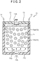
- FIG. 2 is a schematic configuration diagram showing an activated carbon filter 70 (absorption filter) in the boil-off gas recovery system 1 according to the first embodiment.
- FIG. 3 is a schematic configuration diagram showing a re-liquefying system 9 in the boil-off gas recovery system 1 according to the first embodiment.
- the boil-off gas recovery system 1 is installed in a ship that transports a liquefied gas such as a liquefied natural gas.
- the boil-off gas recovery system 1 mainly includes a tank 2, a compressor group 3, a cooler 51, a first separator 14 (oil separation unit), the activated carbon filter 70 (absorption filter), the re-liquefying system 9, pipes connecting these constituent elements to each other, and various control valves provided in the pipes.
- the tank 2 is to store a liquefied gas 100 such as a liquefied natural gas.
- the liquefied natural gas is stored in the tank 2 in a temperature state of about -160°C.
- a boil-off gas 100A is generated.
- the tank 2 is not limited to the one to store the liquefied natural gas but may be the one to store other types of the liquefied gas 100 such as a liquefied petroleum gas.
- the compressor group 3 is connected to the tank 2 via a first pipe 4.
- the boil-off gas 100A generated in the tank 2 passes through the inside of the first pipe 4 and is supplied to the compressor group 3.
- the compressor group 3 includes a non-oil supply type compressor 3a that does not require lubricating oil, and an oil supply type compressor 3b to which the lubricating oil is supplied.
- the non-oil supply type and oil supply type compressors 3a, 3b compress the boil-off gas 100A generated due to vaporization of part of the liquefied gas 100 in the tank 2.
- the oil supply type compressor 3b is arranged in a subsequent part of the non-oil supply type compressor 3a.
- the non-oil supply type compressor 3a may be omitted.
- the non-oil supply type compressor 3a has two compression stages 3aa.
- the oil supply type compressor 3b has three compression stages 3bb.
- the number of the compression stages can be set in accordance with the types of the liquefied gas 100 so that pressure of the boil-off gas can be boosted to be pressure required for re-liquefaction. Therefore, the number of the compression stages is not limited to five of the present embodiment but may be four or less or may be six or more.
- Each of the non-oil supply type and oil supply type compressors 3a, 3b is a reciprocating compressor. That is, the compressors 3a, 3b boost the pressure of the boil-off gas suctioned into a cylinder via a suction port by reciprocating motion of a piston and discharge the boil-off gas whose pressure is boosted from a discharge port.
- a check valve is provided in each of the suction port and the discharge port.
- the cooler 51 is to cool the boil-off gas compressed by the compressors 3a, 3b, and is arranged in a subsequent part of the compressor group 3.
- the cooler 51 cools the boil-off gas by heat exchange with using sea water, for example.
- a temperature of the boil-off gas supplied to an engine 6 and the like can be adjusted to be a predetermined temperature.
- the lubricating oil used in the compressor 3b can be mixed into the boil-off gas discharged from the compressor 3b.
- the lubricating oil in a vaporous state (oil content) contained in the boil-off gas can also be condensed.
- the first separator 14 is to separate the lubricating oil (lubricating oil used in the oil supply type compressor 3b) in a liquid state or a mist state contained in the boil-off gas which is discharged from the compressor 3b, and is arranged in a subsequent part of the cooler 51.
- the first separator 14 is connected to the compressor 3b via a second pipe 5.
- the cooler 51 is provided in the middle of the second pipe 5.
- the first separator 14 has a main body portion 25 having a cylindrical shape, and a small diameter portion 26 having a cylindrical shape whose diameter is smaller than that of the main body portion 25, the small diameter portion being arranged in the main body portion 25. An outer surface of this small diameter portion 26 is formed in a mesh shape.
- the boil-off gas cooled by the cooler 51 passes through the inside of the second pipe 5 and flows into the small diameter portion 26 from the upper end side of the small diameter portion 26 of the first separator 14. As shown by a broken line in FIG. 1 , the boil-off gas flows from an upper end toward a lower end in the small diameter portion 26 and then passes through the mesh on the outer surface of the small diameter portion 26. At this time, the lubricating oil in a liquid state or a mist state contained in the boil-off gas does not pass through the mesh but is accumulated on a bottom of the small diameter portion 26. The boil-off gas passes through the mesh of the small diameter portion 26 and then flows out of the first separator 14 from a gas outlet provided on a side surface of the main body portion 25.
- the lubricating oil contained in the boil-off gas can be separated.
- the oil content accumulated on the bottom of the small diameter portion 26 passes through mesh holes and drips down to a bottom of the main body portion 25 (reference numeral 101 in FIG. 1 ).
- the above boil-off gas recovery system 1 further includes a level sensor 24 provided in the first separator 14, a lead-out means 80 that leads the lubricating oil out of the first separator 14, and a drain tank 90 that stores the lubricating oil led out by the lead-out means 80.
- the level sensor 24 detects whether or not a liquid level of the lubricating oil in the first separator 14 (main body portion 25) exceeds a preliminarily fixed reference level.
- the level sensor 24 has a pair of electrodes, and when the liquid level of the lubricating oil reaches the reference level, a portion between the pair of electrodes is filled with the lubricating oil. At this time, electric resistance between the pair of electrodes is changed. By detecting the change in the electric resistance, the level sensor 24 detects the fact that the liquid level of the lubricating oil in the first separator 14 exceeds the preliminarily fixed reference level.
- the lead-out means 80 leads the lubricating oil out of the first separator 14 when the liquid level of the lubricating oil in the first separator 14 exceeds the reference level.
- the lead-out means 80 has a drain pipe 82, a drain valve 81 provided in the drain pipe 82, and a control unit 83 that controls open/close of the drain valve 81.
- the drain pipe 82 has one end connected to a bottom portion of the first separator 14 (main body portion 25), and the other end connected to an upper portion of the drain tank 90.
- the control unit 83 receives a detection signal indicating the fact that the liquid level of the lubricating oil in the first separator 14 exceeds the reference level from the level sensor 24. Upon receiving this detection signal, the control unit 83 performs control of opening the drain valve 81. Thereby, when the liquid level of the lubricating oil in the first separator 14 exceeds the reference level, the lubricating oil can be guided from the inside of the first separator 14 to the drain tank 90 via the drain pipe 82.
- the activated carbon filter 70 is to absorb the lubricating oil contained in the boil-off gas already passing through the first separator 14, and is arranged in a subsequent part of the first separator 14.
- the activated carbon filter 70 is connected to the first separator 14 by a third pipe 70A. Thereby, the boil-off gas already passing through the first separator 14 can flow into the activated carbon filter 70 via the third pipe 70A.
- FIG. 2 is a vertically sectional diagram showing a detailed configuration of the activated carbon filter 70.
- the activated carbon filter 70 mainly has a casing 71, a lid 73, an activated carbon cartridge 72, and fastening members 74, 75.
- the activated carbon filter 70 is arranged in a posture along the vertical direction (vertically placed).
- the posture of the activated carbon filter 70 to be arranged is not limited to this but the activated carbon filter may be arranged in a posture along the horizontal direction (horizontally placed).
- the casing 71 has a cylindrical shape inside which the activated carbon cartridge 72 can be housed, and an upper end of the casing is opened.
- a gas inflow port 71A for the boil-off gas flowing into the casing 71 is provided in substantially center of a bottom portion 71C of the casing 71.
- the lid 73 has a disc shape of the substantially same diameter as that of the casing 71, and is fixed to an upper end of the casing 71 by the fastening members 74, 75.
- a gas outflow port 73A for the boil-off gas flowing out to the outside is provided.
- the activated carbon cartridge 72 is housed in the casing 71 and can be taken out of the casing 71. Specifically, after the fastening members 74, 75 are removed and the lid 73 is detached from the casing 71, the activated carbon cartridge 72 can be taken out from the upper end opening portion of the casing 71. In such a way, a replacement task of the activated carbon cartridge 72 can be performed.
- the activated carbon cartridge 72 has a large number of particulate activated carbon particles 72A, and a housing portion 72B that houses the activated carbon particles 72A.
- the activated carbon particles 72A can absorb the lubricating oil in a liquid state or a mist state contained in the boil-off gas.
- a space 71B is provided between the activated carbon cartridge 72 and the bottom portion 71C of the casing 71. By providing this space 71B, the boil-off gas flowing into the casing 71 can flow in throughout the inside of the activated carbon cartridge 72.
- the boil-off gas already passing through the first separator 14 flows into the casing 71 from the gas inflow port 71A. As shown by broken arrows in FIG. 2 , the boil-off gas spreads in the radial direction in the space 71B and then passes through the inside of the activated carbon cartridge 72. At this time, the lubricating oil in a liquid state or a mist state contained in the boil-off gas (lubricating oil which is not completely separated by the first separator 14) can be absorbed by the activated carbon particles 72A. The boil-off gas passes through the activated carbon cartridge 72 and then flows out to the outside from the gas outflow port 73A.
- the above boil-off gas recovery system 1 further includes a differential pressure meter 76 and an alarm issuing unit 77.
- the differential pressure meter 76 detects a pressure difference before and after the activated carbon filter 70.
- the alarm issuing unit 77 issues an alarm when the pressure difference detected by the differential pressure meter 76 exceeds a preliminarily fixed reference value.
- the alarm issuing unit 77 may be for example of a sound type or a lighting type.
- One end of a gas outlet pipe 5A is connected to the gas outflow port 73A of the activated carbon filter 70.
- the gas outlet pipe 5A branches into three at a first part 5AA.
- the branching pipes are connected to the engine 6, a gas combustion unit 7, and a generator 8, respectively. Thereby, the boil-off gas already passing through the activated carbon filter 70 can be respectively supplied to the engine 6, the gas combustion unit 7, and the generator 8.
- Control valves may be respectively provided in the branching pipes. By controlling open/close of these control valves, supply amounts of the boil-off gas to the engine 6, the gas combustion unit 7, and the generator 8 can be adjusted.
- the engine 6 generates propulsion force for a ship by combusting the supplied boil-off gas.
- the generator 8 generates electric power required for driving various devices of the ship by performing power generation with the supplied boil-off gas as fuel.
- the gas combustion unit 7 combusts and safely processes an extra boil-off gas in a case where a generation amount of the boil-off gas exceeds an amount required as fuel for the engine 6 and the generator 8.
- the re-liquefying system 9 cools and expands to re-liquefy the boil-off gas whose pressure is boosted by the compressors 3a, 3b.
- the re-liquefying system 9 mainly has a fourth pipe 10, a heat exchanger 16, a fifth pipe 17, an expansion valve 18, a gas-liquid separation unit 19, a sixth pipe 21, and a seventh pipe 20.
- the fourth pipe 10 has one end connected to a second part 5AB of the gas outlet pipe 5A placed on the upstream side of the first part 5AA, and the other end connected to the heat exchanger 16. Thereby, the boil-off gas already passing through the activated carbon filter 70 passes through the gas outlet pipe 5A, flows into the fourth pipe 10 from the second part 5AB, and is supplied to the heat exchanger 16.
- a first control valve 29 is provided in the fourth pipe 10. By controlling open/close of this first control valve 29, an amount of the boil-off gas flowing into the fourth pipe 10 from the gas outlet pipe 5A can be adjusted.
- the heat exchanger 16 cools the boil-off gas to a liquefiable temperature (for example, -100°C). As shown in FIG. 3 , the heat exchanger 16 has a low-temperature side passage 16a through which the boil-off gas fed to the compressors 3a, 3b from the tank 2 passes, and a high-temperature side passage 16b through which the boil-off gas already passing through the activated carbon filter 70 passes.
- a liquefiable temperature for example, -100°C
- the heat exchanger 16 performs heat exchange between the boil-off gas supplied to the compressors 3a, 3b from the tank 2 (boil-off gas passing through the low-temperature side passage 16a) and the boil-off gas already passing through the activated carbon filter 70 (boil-off gas passing through the high-temperature side passage 16b).
- the boil-off gas passing through the high-temperature side passage 16b is cooled.
- part of the boil-off gas may be liquefied.
- the boil-off gas passing through the low-temperature side passage 16a is heated, for example, from -160°C to -50°C.
- the first pipe 4 is connected to an inlet and an outlet of the low-temperature side passage 16a.
- the other end of the fourth pipe 10 is connected to an inlet of the high-temperature side passage 16b.
- One end of the fifth pipe 17 is connected to an outlet of the high-temperature side passage 16b.
- the fifth pipe 17 has the one end connected to the heat exchanger 16, and the other end connected to the gas-liquid separation unit 19.
- the expansion valve 18 is to expand the boil-off gas cooled in the heat exchanger 16 to reduce the pressure, and is provided in the middle of the fifth pipe 17. By this expansion valve 18, part of the boil-off gas is liquefied.
- the gas-liquid separation unit 19 is to separate the partly liquefied boil-off gas into a liquid component and a gas component.
- One end of the sixth pipe 21 and one end of the seventh pipe 20 are respectively connected to the gas-liquid separation unit 19.
- the seventh pipe 20 has the one end connected to a bottom portion of the gas-liquid separation unit 19, and the other end connected to the tank 2. Thereby, the liquid component of the boil-off gas separated in the gas-liquid separation unit 19 can be returned to the tank 2 via the seventh pipe 20.
- the sixth pipe 21 connects the gas-liquid separation unit 19 and the first pipe 4 to each other, and also connects the gas-liquid separation unit 19 and the gas combustion unit 7 to each other.
- the sixth pipe 21 branches into two branching pipes 21A, 21B at a first part 21AA.
- One branching pipe 21A is connected to the first pipe 4 on the outlet side of the heat exchanger 16, and the other branching pipe 21B is connected to the gas combustion unit 7.
- the gas component of the boil-off gas separated in the gas-liquid separation unit 19 can respectively flow into the first pipe 4 and the gas combustion unit 7 via the sixth pipe 21.
- a second control valve 31 and a third control valve 30 are respectively provided in the branching pipes 21A, 21B.
- opening degrees of flow passages of the boil-off gas in the branching pipes 21A, 21B can be adjusted.
- an amount of the boil-off gas flowing into the side of the first pipe 4 and an amount of the boil-off gas flowing into the side of the gas combustion unit 7 can be respectively adjusted.
- the above boil-off gas recovery system 1 includes the tank 2, the compressor 3b to which the lubricating oil is supplied, the compressor that compresses the boil-off gas, the first separator 14 that separates the lubricating oil contained in the boil-off gas which is discharged from the compressor 3b, the activated carbon filter 70 that absorbs the lubricating oil contained in the boil-off gas already passing through the first separator 14, and the re-liquefying system 9 having the heat exchanger 16 that cools the boil-off gas already passing through the activated carbon filter 70, the re-liquefying system where the liquefied boil-off gas is returned to the tank 2.
- the lubricating oil contained in the boil-off gas which is discharged from the compressor 3b is separated by the first separator 14
- the lubricating oil contained in the boil-off gas can be further absorbed by the activated carbon filter 70.
- the amount of the lubricating oil contained in the boil-off gas can be reduced to a great extent.
- concentration of the lubricating oil in the boil-off gas can be reduced to 0.5 ppm or less by the first separator 14, and the concentration can be further reduced to 0.1 ppm or less by the activated carbon filter 70. Therefore, an amount of the oil content flowing into the heat exchanger 16 in the re-liquefying system 9 can be reduced to a great extent. Thus, since precipitation of the oil content in a flow passage of the heat exchanger 16 is suppressed, performance deterioration of the heat exchanger 16 can be suppressed.
- the above boil-off gas recovery system 1 includes the differential pressure meter 76 that detects the pressure difference before and after the activated carbon filter 70, and the alarm issuing unit 77 that issues the alarm when the pressure difference exceeds the preliminarily fixed reference value. Thereby, the end of the life of the activated carbon filter 70 can be recognized by the alarm. Thus, the replacement task of the activated carbon cartridge 72 can be promptly performed.
- the above boil-off gas recovery system 1 includes the level sensor 24 that detects whether or not the liquid level of the lubricating oil in the first separator 14 exceeds the preliminarily fixed reference level, the lead-out means 80 that leads the lubricating oil out of the first separator 14 when the liquid level exceeds the reference level, and the drain tank 90 that stores the lubricating oil led out by the lead-out means 80. Thereby, at timing when the liquid level of the lubricating oil exceeds the reference level, the lubricating oil can be led out of the first separator 14. Thus, maintenance of the first separator 14 is easily performed.
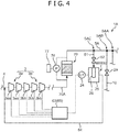
- the boil-off gas recovery system 1A according to the second embodiment basically has the same configuration as the boil-off gas recovery system 1 according to the above first embodiment but is different in terms of a point that a monitoring means that monitors whether or not the lubricating oil is contained in the boil-off gas already passing through the activated carbon filter 70 is further provided.
- a monitoring means that monitors whether or not the lubricating oil is contained in the boil-off gas already passing through the activated carbon filter 70 is further provided.
- FIG. 4 the configurations of the cooler 51, the first separator 14, and the like arranged between the compressor 3b and the activated carbon filter 70 are omitted.
- the boil-off gas recovery system 1A includes a monitoring means 65.
- This monitoring means 65 has a second separator 60 arranged in a subsequent part of the activated carbon filter 70, and a controlling unit 63 that controls actions of the compressors 3a, 3b.
- the above boil-off gas recovery system 1A has a gas branching pipe 61 whose one end is connected to a third part 5AC of the gas outlet pipe 5A on the upstream side of the second part 5AB.
- the other end of this gas branching pipe 61 is connected to an inlet of the second separator 60.
- a fourth control valve 62 is provided in the gas branching pipe 61. By controlling open/close of this fourth control valve 62, an amount of the boil-off gas flowing into the gas branching pipe 61 from the gas outlet pipe 5A can be adjusted.
- the second separator 60 has the same configuration as the first separator 14 described in the above first embodiment. Therefore, with the second separator 60, in a case where the first separator 14 and the activated carbon filter 70 do not sufficiently function and the lubricating oil in a liquid state or a mist state is still contained in the boil-off gas already passing through the activated carbon filter 70, the lubricating oil can be separated. Thus, by the amount of the lubricating oil separated by the second separator 60 (amount of the lubricating oil accumulated on the bottom of the main body portion 25), it can be confirmed whether or not a large amount of the lubricating oil is contained in the boil-off gas flowing through the subsequent part of the activated carbon filter 70. That is, it can be confirmed whether or not the lubricating oil contained in the boil-off gas is sufficiently removed by the first separator 14 and the activated carbon filter 70 in a prior part of the second separator 60.
- a level sensor 24 is provided in the second separator 60 as well as the first separator 14.
- the level sensor 24 detects the fact that a liquid level of the lubricating oil in the second separator 60 exceeds a preliminarily fixed reference level
- a detection signal of the level sensor is sent to the controlling unit 63.
- the controlling unit 63 Upon receiving the detection signal, the controlling unit 63 performs control of stopping the actions of the compressors 3a, 3b. That is, the controlling unit 63 stops the actions of the compressors 3a, 3b when the amount of the lubricating oil separated by the second separator 60 reaches a predetermined amount.
- the above boil-off gas recovery system 1A includes an eighth pipe 64 having one end connected to a gas outlet of the second separator 60, and the other end connected to the first pipe 4. Thereby, the boil-off gas flowing out of the second separator 60 can be returned back to a prior part of the compressor 3a.
- the gas branching pipe 61 may be omitted and the second separator 60 may be arranged in the middle of the gas outlet pipe 5A as shown in FIG. 5 .
- the monitoring means 65 may include no controlling unit 63 but only include the second separator 60. In this case, the worker regularly confirms the amount of the lubricating oil separated by the second separator 60, and when the separation amount of the lubricating oil exceeds a predetermined amount, the worker manually stops the actions of the compressors 3a, 3b.
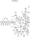
- the boil-off gas recovery system 1B according to the third embodiment basically has the same configuration as the boil-off gas recovery system 1 according to the above first embodiment but is different in terms of a point that plural first separators 14 and plural activated carbon filters 70 are provided and respectively arranged in parallel.
- plural first separators 14 and plural activated carbon filters 70 are provided and respectively arranged in parallel.
- the plural (two in the present embodiment) first separators 14 are provided and arranged in parallel.
- the second pipe 5 branches into two separator upstream pipes 131, 132 at a part 5E.
- the separator upstream pipes 131, 132 are connected to inlets of the first separators 14.
- the third pipe 70A has two separator downstream pipes 133, 134 connected to outlets of the first separators 14.
- the two separator downstream pipes 133, 134 join at a part 5F.
- the above boil-off gas recovery system 1B includes a separator switching means 110 that switches supply of the boil-off gas to the plural first separators 14.
- the separator switching means 110 includes on-off valves 111, 112 provided before and after (on the upstream side and the downstream side of) one of the first separators 14 (on the upper side in FIG. 6 ), and on-off valves 113, 114 provided before and after the other first separator 14 (on the lower side in FIG. 6 ).
- the separator switching means 110 may further include a controller that controls these on-off valves 111 to 114.
- the supply of the boil-off gas to the plural first separators 14 can be switched. Specifically, by closing the on-off valves 111, 112 and opening the on-off valves 113, 114, the boil-off gas can be supplied only to the first separator 14 on the lower side in FIG. 6 . Meanwhile, maintenance or the like of the first separator 14 on the upper side in FIG. 6 can be performed. On the other hand, by opening the on-off valves 111, 112 and closing the on-off valves 113, 114, the boil-off gas can be supplied only to the first separator 14 on the upper side in FIG. 6 .
- the plural (two in the present embodiment) activated carbon filters 70 are provided and arranged in parallel as well as the first separators 14.
- the third pipe 70A branches into two filter upstream pipes 135, 136 at a part 5G.
- the two filter upstream pipes 135, 136 are connected to inlets of the activated carbon filters 70.
- the gas outlet pipe 5A has two filter downstream pipes 137, 138 connected to outlets of the activated carbon filters 70.
- the two filter downstream pipes 137, 138 join at a part 5H.
- the above boil-off gas recovery system 1B includes a filter switching means 120 that switches supply of the boil-off gas to the plural activated carbon filters 70.
- the filter switching means 120 includes on-off valves 121, 122 provided before and after one of the activated carbon filters 70 (on the upper side in FIG. 6 ), and on-off valves 123, 124 provided before and after the other activated carbon filter 70 (on the lower side in FIG. 6 ).
- the filter switching means 120 may further include a controller that controls these on-off valves 121 to 124.
- the supply of the boil-off gas to the plural activated carbon filters 70 can be switched. Specifically, by closing the on-off valves 121, 122 and opening the on-off valves 123, 124, the boil-off gas can be supplied only to the activated carbon filter 70 on the lower side in FIG. 6 . Meanwhile, the replacement task of the activated carbon cartridge 72 or the like can be performed in the activated carbon filter 70 on the upper side in FIG. 6 . On the other hand, by opening the on-off valves 121, 122 and closing the on-off valves 123, 124, the boil-off gas can be supplied only to the activated carbon filter 70 on the upper side in FIG. 6 .
- the plural first separators 14 and the plural activated carbon filters 70 are respectively arranged in parallel, and the means for switching the supply of the boil-off gas to these are provided. Thereby, while continuing an operation of the boil-off gas recovery system 1B, the maintenance of the first separator 14, the replacement task of the activated carbon cartridge 72, and the like can be performed.
- the case where the two first separators 14 and the two activated carbon filters 70 are provided is described.
- three or more first separators and three or more activated carbon filters may be arranged in parallel. Only one of the first separators 14 and the activated carbon filters 70 may be arranged in parallel.
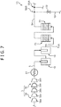
- the boil-off gas recovery system 1C according to the fourth embodiment basically has the same configuration as the boil-off gas recovery system 1 according to the above first embodiment but is different in terms of a point that plural first separators 14 and plural activated carbon filters 70 are provided and respectively arranged in series.
- plural first separators 14 and plural activated carbon filters 70 are provided and respectively arranged in series.
- the plural (two in the present embodiment) first separators 14 are provided and arranged in series.
- the plural (two in the present embodiment) activated carbon filters 70 are provided and arranged in series. Thereby, the boil-off gas discharged from the compressor 3b can pass through the plural first separators 14.
- the boil-off gas already passing through the first separators 14 can pass through the plural activated carbon filters 70. Thereby, the amount of the lubricating oil contained in the boil-off gas can be further reduced.
- the configuration in which the boil-off gas after passing through the last compression stage 3bb is guided to the re-liquefying system 9 is described.
- the present invention is not limited to this.
- the fourth pipe 10 in the re-liquefying system 9 may be connected to a portion between the compression stages 3bb in the oil supply type compressor 3b.
- the cooler 51, the first separator 14, and the activated carbon filter 70 are also arranged in the portion between the compression stages 3bb. Thereby, the boil-off gas extracted from a middle part of the compressor 3b can be guided to the re-liquefying system 9.
- the gas inflow port 71A is provided in a lower portion of the activated carbon filter 70 and the gas outflow port 73A is provided in an upper portion of the activated carbon filter 70 is described.
- the present invention is not limited to this.
- the gas outflow portion may be provided in the lower portion of the activated carbon filter 70 and the gas outflow port may be provided in the upper portion of the activated carbon filter 70.
- the differential pressure meter 76 and the alarm issuing unit 77 may be omitted.
- the level sensor 24, the lead-out means 80, and the drain tank 90 may be omitted.
- the activated carbon filter 70 is described as one example of the absorption filter in the present invention.
- the present invention is not limited to this.
- an absorption filter made of a porous material such as zeolite may be used.
- the cooler 51 may be omitted.
- the first separator 14 having the small diameter portion 26 whose outer surface is formed in a mesh shape is described as one example of the oil separation unit in the present invention.
- the lubricating oil can also be separated by other oil separation units.
- an oil separation unit using a baffle plate or an oil separation unit of centrifugal separation may be used. The same is applied to the second separator 60 included in the monitoring means in the present invention.
- a pipe connecting an arbitrary part of the third pipe 70A and the first part 5AA of the gas outlet pipe 5A may be provided.
- the boil-off gas already passing through the first separator 14 can be directly supplied to the engine 6, the gas combustion unit 7, and the generator 8 while bypassing the activated carbon filter 70.
- a control valve is provided in the pipe.
- the cooler 51 is arranged only in the subsequent part of the fifth compression stage 3bb.
- the cooler 51 may be arranged in a subsequent part of each of the compression stages 3aa, 3bb.
- a boil-off gas recovery system capable of suppressing performance deterioration of a heat exchanger in a boil-off gas re-liquefying system is provided.
- a boil-off gas recovery system includes a tank where a liquefied gas is stored, a reciprocating compressor to which lubricating oil is supplied, the compressor that compresses a boil-off gas generated by vaporization of part of the liquefied gas in the tank, a first separator that separates the lubricating oil contained in the boil-off gas which is discharged from the compressor, an activated carbon filter that absorbs the lubricating oil contained in the boil-off gas already passing through the first separator, and a re-liquefying system having a heat exchanger that cools the boil-off gas already passing through the activated carbon filter by heat exchange with the boil-off gas supplied to the compressor from the tank, the re-liquefying system where the liquefied boil-off gas is returned to the tank.
Landscapes
- Engineering & Computer Science (AREA)
- Mechanical Engineering (AREA)
- General Engineering & Computer Science (AREA)
- Chemical & Material Sciences (AREA)
- Combustion & Propulsion (AREA)
- Ocean & Marine Engineering (AREA)
- Filling Or Discharging Of Gas Storage Vessels (AREA)
Abstract
Description
- The present invention relates to a boil-off gas recovery system.
- In a liquefied natural gas transportation ship, since a liquefied natural gas stored in a tank is gasified by heat coming from the outside when transferred at sea, a boil-off gas is generated. This boil-off gas is effectively utilized as fuel for an engine, a steam boiler, or a generator in the ship, and an extra gas is re-liquefied and then returned to the tank. As a technique to re-liquefy the boil-off gas generated in the tank and to return the boil-off gas to the tank in such a way, a boil-off gas recovery system described in
JP 2015-158263 A - In the boil-off gas recovery system of
JP 2015-158263 A FIG. 9 , a boil-off gas generated in atank 11 is compressed by an oilsupply type compressor 15, and part of the compressed boil-off gas is re-liquefied through cooling by aheat exchanger 14 and expansion by anexpansion valve 17 and then returned to thetank 11. Lubricating oil used in thecompressor 15 can be mixed into the boil-off gas discharged from thecompressor 15. Therefore, in the boil-off gas recovery system ofJP 2015-158263 A second pipe 16. - In the boil-off gas recovery system of
JP 2015-158263 A heat exchanger 14, the flow passage is narrowed down. As a result, there is a problem that a heat exchange performance is deteriorated. - The present invention is achieved in consideration with the above problem, and an object of the present invention is to provide a boil-off gas recovery system capable of suppressing performance deterioration of a heat exchanger in a boil-off gas re-liquefying system.
- A boil-off gas recovery system according to one aspect of the present invention includes a tank where a liquefied gas is stored, a reciprocating compressor to which lubricating oil is supplied, the compressor that compresses a boil-off gas generated by vaporization of part of the liquefied gas in the tank, an oil separation unit that separates the lubricating oil contained in the boil-off gas which is discharged from the compressor, an absorption filter that absorbs the lubricating oil contained in the boil-off gas already passing through the oil separation unit, and a re-liquefying system having a heat exchanger that cools the boil-off gas already passing through the absorption filter by heat exchange with the boil-off gas supplied to the compressor from the tank, the re-liquefying system where the liquefied boil-off gas is returned to the tank. The above absorption filter is preferably an activated carbon filter.
- In the above boil-off gas recovery system, after the lubricating oil contained in the boil-off gas which is discharged from the compressor is separated by the oil separation unit, the lubricating oil contained in the boil-off gas can be further absorbed by the absorption filter. In such a way, by two-step operations of separation of the lubricating oil with the oil separation unit and absorption of the lubricating oil with the absorption filter, an amount of the lubricating oil contained in the boil-off gas can be reduced to a great extent. Therefore, an amount of oil content flowing into the heat exchanger in the re-liquefying system can be reduced to a great extent. Thus, since precipitation of the oil content in a flow passage of the heat exchanger is suppressed, performance deterioration of the heat exchanger can be suppressed. In particular, the activated carbon filter is preferable due to a high ability of absorbing the lubricating oil.
- The above boil-off gas recovery system may further include a monitoring means that monitors whether or not the lubricating oil is contained in the boil-off gas already passing through the absorption filter.
- With this configuration, it can be confirmed whether or not the lubricating oil contained in the boil-off gas is sufficiently removed by the oil separation unit and the absorption filter.
- The above boil-off gas recovery system may further include a differential pressure meter that detects a pressure difference before and after the absorption filter, and an alarm issuing unit that issues an alarm when the pressure difference detected by the differential pressure meter exceeds a preliminarily fixed reference value.
- With this configuration, the end of the life of the absorption filter can be recognized by the alarm. Thus, a replacement task of the absorption filter can be promptly performed.
- The above boil-off gas recovery system may further include a level sensor that detects whether or not a liquid level of the lubricating oil in the oil separation unit exceeds a preliminarily fixed reference level, a lead-out means that leads the lubricating oil out of the oil separation unit when the liquid level exceeds the reference level, and a drain tank that stores the lubricating oil led out by the lead-out means.
- With this configuration, at timing when the liquid level of the lubricating oil exceeds the reference level, the lubricating oil can be led out of the oil separation unit. Thus, maintenance of the oil separation unit is easily performed.
- As clear from the above description, according to the present invention, the boil-off gas recovery system capable of suppressing the performance deterioration of the heat exchanger in the boil-off gas re-liquefying system can be provided.
-
-
FIG. 1 is a diagram schematically showing a configuration of a boil-off gas recovery system according to a first embodiment of the present invention. -
FIG. 2 is a diagram schematically showing a configuration of an activated carbon filter in the above boil-off gas recovery system. -
FIG. 3 is a diagram schematically showing a configuration of a re-liquefying system in the above boil-off gas recovery system. -
FIG. 4 is a diagram schematically showing a configuration of a boil-off gas recovery system according to a second embodiment of the present invention. -
FIG. 5 is a diagram schematically showing a configuration of a boil-off gas recovery system according to a modified example of the above second embodiment. -
FIG. 6 is a diagram schematically showing a configuration of a boil-off gas recovery system according to a third embodiment of the present invention. -
FIG. 7 is a diagram schematically showing a configuration of a boil-off gas recovery system according to a fourth embodiment of the present invention. -
FIG. 8 is a diagram schematically showing a configuration of a boil-off gas recovery system according to one of other embodiments of the present invention. -
FIG. 9 is a diagram schematically showing a configuration of a boil-off gas recovery system according to the conventional example. - Hereinafter, a boil-off gas recovery system according to embodiments of the present invention will be described in detail on the basis of the drawings.
- Firstly, a boil-off gas recovery system 1 according to a first embodiment of the present invention will be described with reference to
FIGS. 1 to 3 .FIG. 1 is a schematic configuration diagram showing the boil-off gas recovery system 1 according to the first embodiment.FIG. 2 is a schematic configuration diagram showing an activated carbon filter 70 (absorption filter) in the boil-off gas recovery system 1 according to the first embodiment.FIG. 3 is a schematic configuration diagram showing a re-liquefyingsystem 9 in the boil-off gas recovery system 1 according to the first embodiment. - The boil-off gas recovery system 1 is installed in a ship that transports a liquefied gas such as a liquefied natural gas. As shown in
FIG. 1 , the boil-off gas recovery system 1 mainly includes atank 2, acompressor group 3, acooler 51, a first separator 14 (oil separation unit), the activated carbon filter 70 (absorption filter), the re-liquefyingsystem 9, pipes connecting these constituent elements to each other, and various control valves provided in the pipes. - The
tank 2 is to store a liquefiedgas 100 such as a liquefied natural gas. The liquefied natural gas is stored in thetank 2 in a temperature state of about -160°C. In thetank 2, by vaporization of part of the liquefiedgas 100 due to in-coming of heat from the outside, a boil-offgas 100A is generated. Thetank 2 is not limited to the one to store the liquefied natural gas but may be the one to store other types of the liquefiedgas 100 such as a liquefied petroleum gas. - The
compressor group 3 is connected to thetank 2 via afirst pipe 4. The boil-offgas 100A generated in thetank 2 passes through the inside of thefirst pipe 4 and is supplied to thecompressor group 3. Thecompressor group 3 includes a non-oilsupply type compressor 3a that does not require lubricating oil, and an oilsupply type compressor 3b to which the lubricating oil is supplied. The non-oil supply type and oilsupply type compressors gas 100A generated due to vaporization of part of the liquefiedgas 100 in thetank 2. The oilsupply type compressor 3b is arranged in a subsequent part of the non-oilsupply type compressor 3a. The non-oilsupply type compressor 3a may be omitted. - The non-oil
supply type compressor 3a has two compression stages 3aa. The oilsupply type compressor 3b has three compression stages 3bb. The number of the compression stages can be set in accordance with the types of the liquefiedgas 100 so that pressure of the boil-off gas can be boosted to be pressure required for re-liquefaction. Therefore, the number of the compression stages is not limited to five of the present embodiment but may be four or less or may be six or more. - Each of the non-oil supply type and oil
supply type compressors compressors - The cooler 51 is to cool the boil-off gas compressed by the
compressors compressor group 3. The cooler 51 cools the boil-off gas by heat exchange with using sea water, for example. By cooling in the cooler 51, a temperature of the boil-off gas supplied to anengine 6 and the like can be adjusted to be a predetermined temperature. The lubricating oil used in thecompressor 3b can be mixed into the boil-off gas discharged from thecompressor 3b. For this, by cooling in the cooler 51, the lubricating oil in a vaporous state (oil content) contained in the boil-off gas can also be condensed. - The
first separator 14 is to separate the lubricating oil (lubricating oil used in the oilsupply type compressor 3b) in a liquid state or a mist state contained in the boil-off gas which is discharged from thecompressor 3b, and is arranged in a subsequent part of the cooler 51. Thefirst separator 14 is connected to thecompressor 3b via asecond pipe 5. The cooler 51 is provided in the middle of thesecond pipe 5. As shown inFIG. 1 , thefirst separator 14 has amain body portion 25 having a cylindrical shape, and asmall diameter portion 26 having a cylindrical shape whose diameter is smaller than that of themain body portion 25, the small diameter portion being arranged in themain body portion 25. An outer surface of thissmall diameter portion 26 is formed in a mesh shape. - The boil-off gas cooled by the cooler 51 passes through the inside of the
second pipe 5 and flows into thesmall diameter portion 26 from the upper end side of thesmall diameter portion 26 of thefirst separator 14. As shown by a broken line inFIG. 1 , the boil-off gas flows from an upper end toward a lower end in thesmall diameter portion 26 and then passes through the mesh on the outer surface of thesmall diameter portion 26. At this time, the lubricating oil in a liquid state or a mist state contained in the boil-off gas does not pass through the mesh but is accumulated on a bottom of thesmall diameter portion 26. The boil-off gas passes through the mesh of thesmall diameter portion 26 and then flows out of thefirst separator 14 from a gas outlet provided on a side surface of themain body portion 25. In such a way, by using a mesh structure of thesmall diameter portion 26, the lubricating oil contained in the boil-off gas can be separated. The oil content accumulated on the bottom of thesmall diameter portion 26 passes through mesh holes and drips down to a bottom of the main body portion 25 (reference numeral 101 inFIG. 1 ). - The above boil-off gas recovery system 1 further includes a
level sensor 24 provided in thefirst separator 14, a lead-out means 80 that leads the lubricating oil out of thefirst separator 14, and adrain tank 90 that stores the lubricating oil led out by the lead-out means 80. - The
level sensor 24 detects whether or not a liquid level of the lubricating oil in the first separator 14 (main body portion 25) exceeds a preliminarily fixed reference level. Specifically, thelevel sensor 24 has a pair of electrodes, and when the liquid level of the lubricating oil reaches the reference level, a portion between the pair of electrodes is filled with the lubricating oil. At this time, electric resistance between the pair of electrodes is changed. By detecting the change in the electric resistance, thelevel sensor 24 detects the fact that the liquid level of the lubricating oil in thefirst separator 14 exceeds the preliminarily fixed reference level. - The lead-out means 80 leads the lubricating oil out of the
first separator 14 when the liquid level of the lubricating oil in thefirst separator 14 exceeds the reference level. The lead-out means 80 has adrain pipe 82, adrain valve 81 provided in thedrain pipe 82, and acontrol unit 83 that controls open/close of thedrain valve 81. - As shown in
FIG. 1 , thedrain pipe 82 has one end connected to a bottom portion of the first separator 14 (main body portion 25), and the other end connected to an upper portion of thedrain tank 90. Thecontrol unit 83 receives a detection signal indicating the fact that the liquid level of the lubricating oil in thefirst separator 14 exceeds the reference level from thelevel sensor 24. Upon receiving this detection signal, thecontrol unit 83 performs control of opening thedrain valve 81. Thereby, when the liquid level of the lubricating oil in thefirst separator 14 exceeds the reference level, the lubricating oil can be guided from the inside of thefirst separator 14 to thedrain tank 90 via thedrain pipe 82. - The activated
carbon filter 70 is to absorb the lubricating oil contained in the boil-off gas already passing through thefirst separator 14, and is arranged in a subsequent part of thefirst separator 14. The activatedcarbon filter 70 is connected to thefirst separator 14 by athird pipe 70A. Thereby, the boil-off gas already passing through thefirst separator 14 can flow into the activatedcarbon filter 70 via thethird pipe 70A. -
FIG. 2 is a vertically sectional diagram showing a detailed configuration of the activatedcarbon filter 70. As shown inFIG. 2 , the activatedcarbon filter 70 mainly has a casing 71, alid 73, an activated carbon cartridge 72, andfastening members carbon filter 70 is arranged in a posture along the vertical direction (vertically placed). However, the posture of the activatedcarbon filter 70 to be arranged is not limited to this but the activated carbon filter may be arranged in a posture along the horizontal direction (horizontally placed). - The casing 71 has a cylindrical shape inside which the activated carbon cartridge 72 can be housed, and an upper end of the casing is opened. In substantially center of a
bottom portion 71C of the casing 71, agas inflow port 71A for the boil-off gas flowing into the casing 71 is provided. Thelid 73 has a disc shape of the substantially same diameter as that of the casing 71, and is fixed to an upper end of the casing 71 by thefastening members lid 73, agas outflow port 73A for the boil-off gas flowing out to the outside is provided. - The activated carbon cartridge 72 is housed in the casing 71 and can be taken out of the casing 71. Specifically, after the
fastening members lid 73 is detached from the casing 71, the activated carbon cartridge 72 can be taken out from the upper end opening portion of the casing 71. In such a way, a replacement task of the activated carbon cartridge 72 can be performed. - The activated carbon cartridge 72 has a large number of particulate activated carbon particles 72A, and a housing portion 72B that houses the activated carbon particles 72A. The activated carbon particles 72A can absorb the lubricating oil in a liquid state or a mist state contained in the boil-off gas. As shown in
FIG. 2 , aspace 71B is provided between the activated carbon cartridge 72 and thebottom portion 71C of the casing 71. By providing thisspace 71B, the boil-off gas flowing into the casing 71 can flow in throughout the inside of the activated carbon cartridge 72. - The boil-off gas already passing through the
first separator 14 flows into the casing 71 from thegas inflow port 71A. As shown by broken arrows inFIG. 2 , the boil-off gas spreads in the radial direction in thespace 71B and then passes through the inside of the activated carbon cartridge 72. At this time, the lubricating oil in a liquid state or a mist state contained in the boil-off gas (lubricating oil which is not completely separated by the first separator 14) can be absorbed by the activated carbon particles 72A. The boil-off gas passes through the activated carbon cartridge 72 and then flows out to the outside from thegas outflow port 73A. In such a way, by performing a separation operation of the lubricating oil with thefirst separator 14 and an absorption operation of the lubricating oil with the activatedcarbon filter 70, an amount of the lubricating oil contained in the boil-off gas can be reduced to a great extent. - As shown in
FIG. 1 , the above boil-off gas recovery system 1 further includes adifferential pressure meter 76 and analarm issuing unit 77. Thedifferential pressure meter 76 detects a pressure difference before and after the activatedcarbon filter 70. Thealarm issuing unit 77 issues an alarm when the pressure difference detected by thedifferential pressure meter 76 exceeds a preliminarily fixed reference value. Thealarm issuing unit 77 may be for example of a sound type or a lighting type. Thereby, a difference between pressure of the boil-off gas flowing into the activated carbon filter 70 (pressure of the boil-off gas on the upstream side of the activated carbon filter 70) and pressure of the boil-off gas flowing out of the activated carbon filter 70 (pressure of the boil-off gas on the downstream side of the activated carbon filter 70) is increased. Thus, by thealarm issuing unit 77, a worker can be notified of the fact that the replacement time for the activated carbon cartridge 72 has come. - One end of a
gas outlet pipe 5A is connected to thegas outflow port 73A of the activatedcarbon filter 70. As shown inFIG. 1 , thegas outlet pipe 5A branches into three at a first part 5AA. The branching pipes are connected to theengine 6, agas combustion unit 7, and agenerator 8, respectively. Thereby, the boil-off gas already passing through the activatedcarbon filter 70 can be respectively supplied to theengine 6, thegas combustion unit 7, and thegenerator 8. - Control valves (not shown) may be respectively provided in the branching pipes. By controlling open/close of these control valves, supply amounts of the boil-off gas to the
engine 6, thegas combustion unit 7, and thegenerator 8 can be adjusted. - The
engine 6 generates propulsion force for a ship by combusting the supplied boil-off gas. Thegenerator 8 generates electric power required for driving various devices of the ship by performing power generation with the supplied boil-off gas as fuel. Thegas combustion unit 7 combusts and safely processes an extra boil-off gas in a case where a generation amount of the boil-off gas exceeds an amount required as fuel for theengine 6 and thegenerator 8. - Next, the
re-liquefying system 9 provided in the above boil-off gas recovery system 1 will be described mainly with reference toFIGS. 1 and3 . There-liquefying system 9 cools and expands to re-liquefy the boil-off gas whose pressure is boosted by thecompressors re-liquefying system 9 mainly has afourth pipe 10, aheat exchanger 16, afifth pipe 17, anexpansion valve 18, a gas-liquid separation unit 19, asixth pipe 21, and aseventh pipe 20. - The
fourth pipe 10 has one end connected to a second part 5AB of thegas outlet pipe 5A placed on the upstream side of the first part 5AA, and the other end connected to theheat exchanger 16. Thereby, the boil-off gas already passing through the activatedcarbon filter 70 passes through thegas outlet pipe 5A, flows into thefourth pipe 10 from the second part 5AB, and is supplied to theheat exchanger 16. As shown inFIG. 1 , afirst control valve 29 is provided in thefourth pipe 10. By controlling open/close of thisfirst control valve 29, an amount of the boil-off gas flowing into thefourth pipe 10 from thegas outlet pipe 5A can be adjusted. - The
heat exchanger 16 cools the boil-off gas to a liquefiable temperature (for example, -100°C). As shown inFIG. 3 , theheat exchanger 16 has a low-temperature side passage 16a through which the boil-off gas fed to thecompressors tank 2 passes, and a high-temperature side passage 16b through which the boil-off gas already passing through the activatedcarbon filter 70 passes. - The
heat exchanger 16 performs heat exchange between the boil-off gas supplied to thecompressors temperature side passage 16a) and the boil-off gas already passing through the activated carbon filter 70 (boil-off gas passing through the high-temperature side passage 16b). By this heat exchange, the boil-off gas passing through the high-temperature side passage 16b is cooled. At this time, part of the boil-off gas may be liquefied. The boil-off gas passing through the low-temperature side passage 16a is heated, for example, from -160°C to -50°C. - As shown in
FIG. 3 , thefirst pipe 4 is connected to an inlet and an outlet of the low-temperature side passage 16a. The other end of thefourth pipe 10 is connected to an inlet of the high-temperature side passage 16b. One end of thefifth pipe 17 is connected to an outlet of the high-temperature side passage 16b. - The
fifth pipe 17 has the one end connected to theheat exchanger 16, and the other end connected to the gas-liquid separation unit 19. Theexpansion valve 18 is to expand the boil-off gas cooled in theheat exchanger 16 to reduce the pressure, and is provided in the middle of thefifth pipe 17. By thisexpansion valve 18, part of the boil-off gas is liquefied. - The gas-
liquid separation unit 19 is to separate the partly liquefied boil-off gas into a liquid component and a gas component. One end of thesixth pipe 21 and one end of theseventh pipe 20 are respectively connected to the gas-liquid separation unit 19. - The
seventh pipe 20 has the one end connected to a bottom portion of the gas-liquid separation unit 19, and the other end connected to thetank 2. Thereby, the liquid component of the boil-off gas separated in the gas-liquid separation unit 19 can be returned to thetank 2 via theseventh pipe 20. - The
sixth pipe 21 connects the gas-liquid separation unit 19 and thefirst pipe 4 to each other, and also connects the gas-liquid separation unit 19 and thegas combustion unit 7 to each other. Specifically, thesixth pipe 21 branches into two branchingpipes pipe 21A is connected to thefirst pipe 4 on the outlet side of theheat exchanger 16, and the other branchingpipe 21B is connected to thegas combustion unit 7. Thereby, the gas component of the boil-off gas separated in the gas-liquid separation unit 19 can respectively flow into thefirst pipe 4 and thegas combustion unit 7 via thesixth pipe 21. - As shown in
FIG. 3 , asecond control valve 31 and athird control valve 30 are respectively provided in the branchingpipes pipes first pipe 4 and an amount of the boil-off gas flowing into the side of thegas combustion unit 7 can be respectively adjusted. - Characteristic configurations and operations and effects of the boil-off gas recovery system 1 according to the above first embodiment will be described.
- The above boil-off gas recovery system 1 includes the
tank 2, thecompressor 3b to which the lubricating oil is supplied, the compressor that compresses the boil-off gas, thefirst separator 14 that separates the lubricating oil contained in the boil-off gas which is discharged from thecompressor 3b, the activatedcarbon filter 70 that absorbs the lubricating oil contained in the boil-off gas already passing through thefirst separator 14, and there-liquefying system 9 having theheat exchanger 16 that cools the boil-off gas already passing through the activatedcarbon filter 70, the re-liquefying system where the liquefied boil-off gas is returned to thetank 2. - In the above boil-off gas recovery system 1, after the lubricating oil contained in the boil-off gas which is discharged from the
compressor 3b is separated by thefirst separator 14, the lubricating oil contained in the boil-off gas can be further absorbed by the activatedcarbon filter 70. In such a way, by two-step operations of separation of the lubricating oil with thefirst separator 14 and absorption of the lubricating oil with the activatedcarbon filter 70, the amount of the lubricating oil contained in the boil-off gas can be reduced to a great extent. Specifically, concentration of the lubricating oil in the boil-off gas can be reduced to 0.5 ppm or less by thefirst separator 14, and the concentration can be further reduced to 0.1 ppm or less by the activatedcarbon filter 70. Therefore, an amount of the oil content flowing into theheat exchanger 16 in there-liquefying system 9 can be reduced to a great extent. Thus, since precipitation of the oil content in a flow passage of theheat exchanger 16 is suppressed, performance deterioration of theheat exchanger 16 can be suppressed. - The above boil-off gas recovery system 1 includes the
differential pressure meter 76 that detects the pressure difference before and after the activatedcarbon filter 70, and thealarm issuing unit 77 that issues the alarm when the pressure difference exceeds the preliminarily fixed reference value. Thereby, the end of the life of the activatedcarbon filter 70 can be recognized by the alarm. Thus, the replacement task of the activated carbon cartridge 72 can be promptly performed. - The above boil-off gas recovery system 1 includes the
level sensor 24 that detects whether or not the liquid level of the lubricating oil in thefirst separator 14 exceeds the preliminarily fixed reference level, the lead-out means 80 that leads the lubricating oil out of thefirst separator 14 when the liquid level exceeds the reference level, and thedrain tank 90 that stores the lubricating oil led out by the lead-out means 80. Thereby, at timing when the liquid level of the lubricating oil exceeds the reference level, the lubricating oil can be led out of thefirst separator 14. Thus, maintenance of thefirst separator 14 is easily performed. - Next, a boil-off
gas recovery system 1A according to a second embodiment of the present invention will be described with reference toFIG. 4 . The boil-offgas recovery system 1A according to the second embodiment basically has the same configuration as the boil-off gas recovery system 1 according to the above first embodiment but is different in terms of a point that a monitoring means that monitors whether or not the lubricating oil is contained in the boil-off gas already passing through the activatedcarbon filter 70 is further provided. Hereinafter, only the point which is different from the above first embodiment will be described. InFIG. 4 , the configurations of the cooler 51, thefirst separator 14, and the like arranged between thecompressor 3b and the activatedcarbon filter 70 are omitted. - As shown in
FIG. 4 , the boil-offgas recovery system 1A according to the second embodiment includes a monitoring means 65. This monitoring means 65 has asecond separator 60 arranged in a subsequent part of the activatedcarbon filter 70, and a controllingunit 63 that controls actions of thecompressors - More specifically, the above boil-off
gas recovery system 1A has agas branching pipe 61 whose one end is connected to a third part 5AC of thegas outlet pipe 5A on the upstream side of the second part 5AB. The other end of thisgas branching pipe 61 is connected to an inlet of thesecond separator 60. Thereby, the boil-off gas already passing through the activatedcarbon filter 70 can flow into thegas branching pipe 61 from the third part 5AC and can be supplied to thesecond separator 60. Afourth control valve 62 is provided in thegas branching pipe 61. By controlling open/close of thisfourth control valve 62, an amount of the boil-off gas flowing into thegas branching pipe 61 from thegas outlet pipe 5A can be adjusted. - The
second separator 60 has the same configuration as thefirst separator 14 described in the above first embodiment. Therefore, with thesecond separator 60, in a case where thefirst separator 14 and the activatedcarbon filter 70 do not sufficiently function and the lubricating oil in a liquid state or a mist state is still contained in the boil-off gas already passing through the activatedcarbon filter 70, the lubricating oil can be separated. Thus, by the amount of the lubricating oil separated by the second separator 60 (amount of the lubricating oil accumulated on the bottom of the main body portion 25), it can be confirmed whether or not a large amount of the lubricating oil is contained in the boil-off gas flowing through the subsequent part of the activatedcarbon filter 70. That is, it can be confirmed whether or not the lubricating oil contained in the boil-off gas is sufficiently removed by thefirst separator 14 and the activatedcarbon filter 70 in a prior part of thesecond separator 60. - A
level sensor 24 is provided in thesecond separator 60 as well as thefirst separator 14. When thelevel sensor 24 detects the fact that a liquid level of the lubricating oil in thesecond separator 60 exceeds a preliminarily fixed reference level, a detection signal of the level sensor is sent to the controllingunit 63. Upon receiving the detection signal, the controllingunit 63 performs control of stopping the actions of thecompressors unit 63 stops the actions of thecompressors second separator 60 reaches a predetermined amount. Thereby, even in a case where the lubricating oil in the boil-off gas is not sufficiently removed by thefirst separator 14 and the activatedcarbon filter 70 for some reasons (failure), the boil-off gas containing a large amount of the lubricating oil can be prevented from flowing to the side of there-liquefying system 9. - As shown in
FIG. 4 , the above boil-offgas recovery system 1A includes aneighth pipe 64 having one end connected to a gas outlet of thesecond separator 60, and the other end connected to thefirst pipe 4. Thereby, the boil-off gas flowing out of thesecond separator 60 can be returned back to a prior part of thecompressor 3a. - The
gas branching pipe 61 may be omitted and thesecond separator 60 may be arranged in the middle of thegas outlet pipe 5A as shown inFIG. 5 . The monitoring means 65 may include no controllingunit 63 but only include thesecond separator 60. In this case, the worker regularly confirms the amount of the lubricating oil separated by thesecond separator 60, and when the separation amount of the lubricating oil exceeds a predetermined amount, the worker manually stops the actions of thecompressors - Next, a boil-off
gas recovery system 1B according to a third embodiment of the present invention will be described with reference toFIG. 6 . The boil-offgas recovery system 1B according to the third embodiment basically has the same configuration as the boil-off gas recovery system 1 according to the above first embodiment but is different in terms of a point that pluralfirst separators 14 and plural activatedcarbon filters 70 are provided and respectively arranged in parallel. Hereinafter, only the point which is different from the above first embodiment will be described in detail. - As shown in
FIG. 6 , the plural (two in the present embodiment)first separators 14 are provided and arranged in parallel. Specifically, thesecond pipe 5 branches into two separatorupstream pipes part 5E. The separatorupstream pipes first separators 14. Thethird pipe 70A has two separatordownstream pipes first separators 14. The two separatordownstream pipes part 5F. - The above boil-off
gas recovery system 1B includes a separator switching means 110 that switches supply of the boil-off gas to the pluralfirst separators 14. The separator switching means 110 includes on-offvalves FIG. 6 ), and on-offvalves FIG. 6 ). The separator switching means 110 may further include a controller that controls these on-offvalves 111 to 114. - By controlling the on-off
valves 111 to 114, the supply of the boil-off gas to the pluralfirst separators 14 can be switched. Specifically, by closing the on-offvalves valves first separator 14 on the lower side inFIG. 6 . Meanwhile, maintenance or the like of thefirst separator 14 on the upper side inFIG. 6 can be performed. On the other hand, by opening the on-offvalves valves first separator 14 on the upper side inFIG. 6 . - As shown in
FIG. 6 , the plural (two in the present embodiment) activatedcarbon filters 70 are provided and arranged in parallel as well as thefirst separators 14. Specifically, thethird pipe 70A branches into two filterupstream pipes part 5G. The two filterupstream pipes gas outlet pipe 5A has two filterdownstream pipes downstream pipes part 5H. - The above boil-off
gas recovery system 1B includes a filter switching means 120 that switches supply of the boil-off gas to the plural activated carbon filters 70. The filter switching means 120 includes on-offvalves FIG. 6 ), and on-offvalves FIG. 6 ). The filter switching means 120 may further include a controller that controls these on-offvalves 121 to 124. - By controlling the on-off
valves 121 to 124, the supply of the boil-off gas to the plural activatedcarbon filters 70 can be switched. Specifically, by closing the on-offvalves valves carbon filter 70 on the lower side inFIG. 6 . Meanwhile, the replacement task of the activated carbon cartridge 72 or the like can be performed in the activatedcarbon filter 70 on the upper side inFIG. 6 . On the other hand, by opening the on-offvalves valves carbon filter 70 on the upper side inFIG. 6 . - In such a way, in the boil-off
gas recovery system 1B according to the third embodiment, the pluralfirst separators 14 and the plural activatedcarbon filters 70 are respectively arranged in parallel, and the means for switching the supply of the boil-off gas to these are provided. Thereby, while continuing an operation of the boil-offgas recovery system 1B, the maintenance of thefirst separator 14, the replacement task of the activated carbon cartridge 72, and the like can be performed. - In the third embodiment, the case where the two
first separators 14 and the two activatedcarbon filters 70 are provided is described. However, three or more first separators and three or more activated carbon filters may be arranged in parallel. Only one of thefirst separators 14 and the activatedcarbon filters 70 may be arranged in parallel. - Next, a boil-off
gas recovery system 1C according to a fourth embodiment of the present invention will be described with reference toFIG. 7 . The boil-offgas recovery system 1C according to the fourth embodiment basically has the same configuration as the boil-off gas recovery system 1 according to the above first embodiment but is different in terms of a point that pluralfirst separators 14 and plural activatedcarbon filters 70 are provided and respectively arranged in series. Hereinafter, only the point which is different from the above first embodiment will be described in detail. - As shown in
FIG. 7 , the plural (two in the present embodiment)first separators 14 are provided and arranged in series. The plural (two in the present embodiment) activatedcarbon filters 70 are provided and arranged in series. Thereby, the boil-off gas discharged from thecompressor 3b can pass through the pluralfirst separators 14. The boil-off gas already passing through thefirst separators 14 can pass through the plural activated carbon filters 70. Thereby, the amount of the lubricating oil contained in the boil-off gas can be further reduced. - Finally, other embodiments of the present invention will be described.
- In the above first embodiment, the configuration in which the boil-off gas after passing through the last compression stage 3bb is guided to the
re-liquefying system 9 is described. However, the present invention is not limited to this. As shown inFIG. 8 , thefourth pipe 10 in there-liquefying system 9 may be connected to a portion between the compression stages 3bb in the oilsupply type compressor 3b. In this case, the cooler 51, thefirst separator 14, and the activatedcarbon filter 70 are also arranged in the portion between the compression stages 3bb. Thereby, the boil-off gas extracted from a middle part of thecompressor 3b can be guided to there-liquefying system 9. - In the above first embodiment, the case where the
gas inflow port 71A is provided in a lower portion of the activatedcarbon filter 70 and thegas outflow port 73A is provided in an upper portion of the activatedcarbon filter 70 is described. However, the present invention is not limited to this. The gas outflow portion may be provided in the lower portion of the activatedcarbon filter 70 and the gas outflow port may be provided in the upper portion of the activatedcarbon filter 70. - In the above first to fourth embodiments, the
differential pressure meter 76 and thealarm issuing unit 77 may be omitted. Thelevel sensor 24, the lead-out means 80, and thedrain tank 90 may be omitted. - In the above first to fourth embodiments, the activated
carbon filter 70 is described as one example of the absorption filter in the present invention. However, the present invention is not limited to this. For example, an absorption filter made of a porous material such as zeolite may be used. - In the boil-off gas recovery system according to the above first to fourth embodiments, the cooler 51 may be omitted.
- In the above embodiments, the
first separator 14 having thesmall diameter portion 26 whose outer surface is formed in a mesh shape is described as one example of the oil separation unit in the present invention. However, the lubricating oil can also be separated by other oil separation units. For example, an oil separation unit using a baffle plate or an oil separation unit of centrifugal separation may be used. The same is applied to thesecond separator 60 included in the monitoring means in the present invention. - In the above first embodiment, a pipe connecting an arbitrary part of the
third pipe 70A and the first part 5AA of thegas outlet pipe 5A may be provided. Thereby, the boil-off gas already passing through thefirst separator 14 can be directly supplied to theengine 6, thegas combustion unit 7, and thegenerator 8 while bypassing the activatedcarbon filter 70. A control valve is provided in the pipe. - In the above first embodiment, the case where the cooler 51 is arranged only in the subsequent part of the fifth compression stage 3bb is described. However, the cooler 51 may be arranged in a subsequent part of each of the compression stages 3aa, 3bb.
- The embodiments disclosed herein should be understood as not restriction but only examples in all aspects. The scope of the present invention is indicated not by the above description but by the claims, and is intended to include equivalent meanings to the claims and all modifications within the scope.
- A boil-off gas recovery system capable of suppressing performance deterioration of a heat exchanger in a boil-off gas re-liquefying system is provided.
- A boil-off gas recovery system includes a tank where a liquefied gas is stored, a reciprocating compressor to which lubricating oil is supplied, the compressor that compresses a boil-off gas generated by vaporization of part of the liquefied gas in the tank, a first separator that separates the lubricating oil contained in the boil-off gas which is discharged from the compressor, an activated carbon filter that absorbs the lubricating oil contained in the boil-off gas already passing through the first separator, and a re-liquefying system having a heat exchanger that cools the boil-off gas already passing through the activated carbon filter by heat exchange with the boil-off gas supplied to the compressor from the tank, the re-liquefying system where the liquefied boil-off gas is returned to the tank.
Claims (5)
- A boil-off gas recovery system comprising:a tank where a liquefied gas is stored;a reciprocating compressor to which lubricating oil is supplied, the compressor that compresses a boil-off gas generated by vaporization of part of the liquefied gas in the tank;an oil separation unit that separates the lubricating oil contained in the boil-off gas which is discharged from the compressor;an absorption filter that absorbs the lubricating oil contained in the boil-off gas already passing through the oil separation unit; anda re-liquefying system having a heat exchanger that cools the boil-off gas already passing through the absorption filter by heat exchange with the boil-off gas supplied to the compressor from the tank, the re-liquefying system where the liquefied boil-off gas is returned to the tank.
- The boil-off gas recovery system according to claim 1, further comprising:a monitoring means that monitors whether or not the lubricating oil is contained in the boil-off gas already passing through the absorption filter.
- The boil-off gas recovery system according to claim 1 or 2, further comprising:a differential pressure meter that detects a pressure difference before and after the absorption filter; andan alarm issuing unit that issues an alarm when the pressure difference detected by the differential pressure meter exceeds a preliminarily fixed reference value.
- The boil-off gas recovery system according to any one of claims 1 to 3, further comprising:a level sensor that detects whether or not a liquid level of the lubricating oil in the oil separation unit exceeds a preliminarily fixed reference level;a lead-out means that leads the lubricating oil out of the oil separation unit when the liquid level exceeds the reference level; anda drain tank that stores the lubricating oil led out by the lead-out means.
- The boil-off gas recovery system according to any one of claims 1 to 4, wherein the absorption filter is an activated carbon filter.
Applications Claiming Priority (1)
| Application Number | Priority Date | Filing Date | Title |
|---|---|---|---|
| JP2017019762A JP6793052B2 (en) | 2017-02-06 | 2017-02-06 | Boil-off gas recovery system |
Publications (2)
| Publication Number | Publication Date |
|---|---|
| EP3358239A1 true EP3358239A1 (en) | 2018-08-08 |
| EP3358239B1 EP3358239B1 (en) | 2021-08-18 |
Family
ID=60888181
Family Applications (1)
| Application Number | Title | Priority Date | Filing Date |
|---|---|---|---|
| EP17207990.7A Active EP3358239B1 (en) | 2017-02-06 | 2017-12-18 | Boil-off gas recovery system |
Country Status (4)
| Country | Link |
|---|---|
| EP (1) | EP3358239B1 (en) |
| JP (1) | JP6793052B2 (en) |
| KR (1) | KR102122994B1 (en) |
| CN (1) | CN108397686B (en) |
Cited By (1)
| Publication number | Priority date | Publication date | Assignee | Title |
|---|---|---|---|---|
| GR1010037B (en) * | 2019-07-22 | 2021-06-29 | Kabushiki Kaisha Kobe Seiko Sho (Kobe Steel, Ltd.) | Control method of compressor unit, compressor unit and compression stage |
Families Citing this family (8)
| Publication number | Priority date | Publication date | Assignee | Title |
|---|---|---|---|---|
| JP7036702B2 (en) * | 2018-10-30 | 2022-03-15 | 株式会社神戸製鋼所 | Compressor |
| JP7179650B2 (en) * | 2019-02-27 | 2022-11-29 | 三菱重工マリンマシナリ株式会社 | Boil-off gas treatment system and ship |
| KR102142940B1 (en) * | 2019-04-09 | 2020-08-11 | 가부시키가이샤 고베 세이코쇼 | Compressor unit and stopping method of compressor unit |
| JP7090585B2 (en) * | 2019-07-24 | 2022-06-24 | 株式会社三井E&Sマシナリー | Boil-off gas supply / recovery device and boil-off gas supply / recovery method |
| KR102067617B1 (en) * | 2019-09-19 | 2020-01-17 | 대운산업기계 주식회사 | Cartridge Type Activated Carbon Adsorption Device |
| JP2022157755A (en) * | 2021-03-31 | 2022-10-14 | 川崎重工業株式会社 | Gas treatment system and ship |
| JP7009669B1 (en) * | 2021-08-31 | 2022-01-25 | 株式会社神戸製鋼所 | How to operate the compressor unit, screw compressor and compressor unit |
| JP7135227B1 (en) * | 2022-02-08 | 2022-09-12 | 株式会社神戸製鋼所 | screw compressor |
Citations (5)
| Publication number | Priority date | Publication date | Assignee | Title |
|---|---|---|---|---|
| GB2292597A (en) * | 1992-03-27 | 1996-02-28 | Mitsubishi Electric Corp | Cryostat for cooling a superconducting magnet |
| JP2001065795A (en) * | 1999-08-31 | 2001-03-16 | Kobe Steel Ltd | Processing method and device for boil-off gas of low temperature liquefied gas |
| JP2015158263A (en) | 2014-02-25 | 2015-09-03 | 三井造船株式会社 | boil-off gas recovery system |
| KR20160095599A (en) * | 2015-02-03 | 2016-08-11 | 삼성중공업 주식회사 | Fuel gas supplying system in ships |
| KR20160126955A (en) * | 2016-10-24 | 2016-11-02 | 대우조선해양 주식회사 | Reliquefaction System And Method For Boil Off Gas |
Family Cites Families (12)
| Publication number | Priority date | Publication date | Assignee | Title |
|---|---|---|---|---|
| DE3001675A1 (en) * | 1980-01-18 | 1981-07-23 | Fichtel & Sachs Ag, 8720 Schweinfurt | DEVICE FOR DISPLAYING THE EXHAUST LEVEL OF AN ADSORPTION FILTER |
| JPS6262100A (en) * | 1985-09-11 | 1987-03-18 | Mitsubishi Heavy Ind Ltd | Control unit for transferring system having group of tank |
| JPS62114187U (en) * | 1986-01-09 | 1987-07-20 | ||
| US5724832A (en) * | 1995-03-29 | 1998-03-10 | Mmr Technologies, Inc. | Self-cleaning cryogenic refrigeration system |
| CN2921725Y (en) * | 2006-05-12 | 2007-07-11 | 苏州昆拓冷机有限公司 | Compression refrigerating system oil separator |
| EA022697B1 (en) * | 2008-04-30 | 2016-02-29 | Эксонмобил Апстрим Рисерч Компани | Method and system for selective removal of oil from gas stream comprising methane |
| KR20140075574A (en) * | 2012-12-11 | 2014-06-19 | 대우조선해양 주식회사 | Partial reliquefaction system of boil-off gas for a ship |
| KR101640768B1 (en) * | 2013-06-26 | 2016-07-29 | 대우조선해양 주식회사 | Method for building a ship |
| CN203437257U (en) * | 2013-08-30 | 2014-02-19 | 大连绿亿环保科技有限公司 | Spray organic waste gas purifying processing system |
| GB201316227D0 (en) * | 2013-09-12 | 2013-10-30 | Cryostar Sas | High pressure gas supply system |
| WO2016126025A1 (en) * | 2015-02-03 | 2016-08-11 | 삼성중공업 주식회사 | Fuel gas supply system for ship |
| EP3305645B1 (en) * | 2015-06-02 | 2024-01-03 | Hanwha Ocean Co., Ltd. | Boil-off gas treatment system for a ship |
-
2017
- 2017-02-06 JP JP2017019762A patent/JP6793052B2/en active Active
- 2017-12-18 EP EP17207990.7A patent/EP3358239B1/en active Active
-
2018
- 2018-02-01 KR KR1020180012638A patent/KR102122994B1/en active IP Right Grant
- 2018-02-06 CN CN201810117671.4A patent/CN108397686B/en active Active
Patent Citations (5)
| Publication number | Priority date | Publication date | Assignee | Title |
|---|---|---|---|---|
| GB2292597A (en) * | 1992-03-27 | 1996-02-28 | Mitsubishi Electric Corp | Cryostat for cooling a superconducting magnet |
| JP2001065795A (en) * | 1999-08-31 | 2001-03-16 | Kobe Steel Ltd | Processing method and device for boil-off gas of low temperature liquefied gas |
| JP2015158263A (en) | 2014-02-25 | 2015-09-03 | 三井造船株式会社 | boil-off gas recovery system |
| KR20160095599A (en) * | 2015-02-03 | 2016-08-11 | 삼성중공업 주식회사 | Fuel gas supplying system in ships |
| KR20160126955A (en) * | 2016-10-24 | 2016-11-02 | 대우조선해양 주식회사 | Reliquefaction System And Method For Boil Off Gas |
Cited By (1)
| Publication number | Priority date | Publication date | Assignee | Title |
|---|---|---|---|---|
| GR1010037B (en) * | 2019-07-22 | 2021-06-29 | Kabushiki Kaisha Kobe Seiko Sho (Kobe Steel, Ltd.) | Control method of compressor unit, compressor unit and compression stage |
Also Published As
| Publication number | Publication date |
|---|---|
| CN108397686B (en) | 2021-11-26 |
| JP2018128039A (en) | 2018-08-16 |
| EP3358239B1 (en) | 2021-08-18 |
| KR102122994B1 (en) | 2020-06-16 |
| CN108397686A (en) | 2018-08-14 |
| JP6793052B2 (en) | 2020-12-02 |
| KR20180091721A (en) | 2018-08-16 |
Similar Documents
| Publication | Publication Date | Title |
|---|---|---|
| EP3358239B1 (en) | Boil-off gas recovery system | |
| RU2442012C2 (en) | Oil separator for combustion engines with gas fuel performance | |
| EP3358285B1 (en) | Boil-off gas recovery system | |
| JP6986130B2 (en) | Lubricating oil discharge method in evaporative gas reliquefaction system and evaporative gas reliquefaction system | |
| US10254041B2 (en) | System and method for processing a hydrocarbon-comprising fluid | |
| KR20180089283A (en) | Boil-off gas recovery system | |
| JP6929391B2 (en) | Evaporative gas reliquefaction system and ships | |
| JP6371930B1 (en) | Lubricating oil discharge method in evaporative gas reliquefaction system | |
| KR20190014000A (en) | Boil-Off Gas Reliquefaction System and Method of Discharging Lubrication Oil in the Same, and Method of Supplying Fuel for Engine | |
| KR20140096184A (en) | Voc recovery system | |
| KR102514081B1 (en) | Lubricating oil separator and boil-off gas reliquefaction system having the lubricating oil separator | |
| US9988990B2 (en) | Dual fuel generator system | |
| JP6422087B1 (en) | Evaporative gas reliquefaction system and method for discharging lubricating oil in evaporative gas reliquefaction system | |
| EP3663184A1 (en) | Boil-off gas reliquefaction system and method for discharging lubricating oil in boil-off gas reliquefaction system | |
| KR101957321B1 (en) | Boil-Off Gas Reliquefaction System | |
| KR101908572B1 (en) | Boil-Off Gas Reliquefaction System and Method of Discharging Lubrication Oil in the Same | |
| KR101957323B1 (en) | Boil-Off Gas Reliquefaction System | |
| RU2527922C1 (en) | Installation for hydrocarbon gas preparation | |
| CN208238390U (en) | Helium gas compression purifier group system | |
| KR20190081149A (en) | Lubricating oil separator and boil-off gas reliquefaction system having the lubricating oil separator | |
| KR101989875B1 (en) | Boil-Off Gas Reliquefaction System and Method of Discharging Lubrication Oil in the Same | |
| KR101938178B1 (en) | Boil-Off Gas Reliquefaction System and Method of Discharging Lubrication Oil in the Same | |
| KR101938181B1 (en) | Method of Discharging LubricationOil in Boil-Off Gas Reliquefaction System and Method of SupplyingFuelfor Engine | |
| KR101938175B1 (en) | Boil-Off Gas Reliquefaction System and Method of Discharging Lubrication Oil in the Same | |
| JP2023115756A (en) | screw compressor |
Legal Events
| Date | Code | Title | Description |
|---|---|---|---|
| PUAI | Public reference made under article 153(3) epc to a published international application that has entered the european phase |
Free format text: ORIGINAL CODE: 0009012 |
|
| STAA | Information on the status of an ep patent application or granted ep patent |
Free format text: STATUS: REQUEST FOR EXAMINATION WAS MADE |
|
| 17P | Request for examination filed |
Effective date: 20171218 |
|
| AK | Designated contracting states |
Kind code of ref document: A1 Designated state(s): AL AT BE BG CH CY CZ DE DK EE ES FI FR GB GR HR HU IE IS IT LI LT LU LV MC MK MT NL NO PL PT RO RS SE SI SK SM TR |
|
| AX | Request for extension of the european patent |
Extension state: BA ME |
|
| STAA | Information on the status of an ep patent application or granted ep patent |
Free format text: STATUS: EXAMINATION IS IN PROGRESS |
|
| 17Q | First examination report despatched |
Effective date: 20201001 |
|
| STAA | Information on the status of an ep patent application or granted ep patent |
Free format text: STATUS: EXAMINATION IS IN PROGRESS |
|
| GRAP | Despatch of communication of intention to grant a patent |
Free format text: ORIGINAL CODE: EPIDOSNIGR1 |
|
| STAA | Information on the status of an ep patent application or granted ep patent |
Free format text: STATUS: GRANT OF PATENT IS INTENDED |
|
| INTG | Intention to grant announced |
Effective date: 20210428 |
|
| GRAS | Grant fee paid |
Free format text: ORIGINAL CODE: EPIDOSNIGR3 |
|
| GRAA | (expected) grant |
Free format text: ORIGINAL CODE: 0009210 |
|
| STAA | Information on the status of an ep patent application or granted ep patent |
Free format text: STATUS: THE PATENT HAS BEEN GRANTED |
|
| AK | Designated contracting states |
Kind code of ref document: B1 Designated state(s): AL AT BE BG CH CY CZ DE DK EE ES FI FR GB GR HR HU IE IS IT LI LT LU LV MC MK MT NL NO PL PT RO RS SE SI SK SM TR |
|
| REG | Reference to a national code |
Ref country code: GB Ref legal event code: FG4D |
|
| REG | Reference to a national code |
Ref country code: CH Ref legal event code: EP |
|
| REG | Reference to a national code |
Ref country code: DE Ref legal event code: R096 Ref document number: 602017044200 Country of ref document: DE |
|
| REG | Reference to a national code |
Ref country code: IE Ref legal event code: FG4D Ref country code: AT Ref legal event code: REF Ref document number: 1421954 Country of ref document: AT Kind code of ref document: T Effective date: 20210915 |
|
| REG | Reference to a national code |
Ref country code: NO Ref legal event code: T2 Effective date: 20210818 |
|
| REG | Reference to a national code |
Ref country code: GR Ref legal event code: EP Ref document number: 20210402646 Country of ref document: GR Effective date: 20211111 |
|
| REG | Reference to a national code |
Ref country code: LT Ref legal event code: MG9D |
|
| REG | Reference to a national code |
Ref country code: NL Ref legal event code: MP Effective date: 20210818 |
|
| REG | Reference to a national code |
Ref country code: AT Ref legal event code: MK05 Ref document number: 1421954 Country of ref document: AT Kind code of ref document: T Effective date: 20210818 |
|
| PG25 | Lapsed in a contracting state [announced via postgrant information from national office to epo] |
Ref country code: SE Free format text: LAPSE BECAUSE OF FAILURE TO SUBMIT A TRANSLATION OF THE DESCRIPTION OR TO PAY THE FEE WITHIN THE PRESCRIBED TIME-LIMIT Effective date: 20210818 Ref country code: RS Free format text: LAPSE BECAUSE OF FAILURE TO SUBMIT A TRANSLATION OF THE DESCRIPTION OR TO PAY THE FEE WITHIN THE PRESCRIBED TIME-LIMIT Effective date: 20210818 Ref country code: HR Free format text: LAPSE BECAUSE OF FAILURE TO SUBMIT A TRANSLATION OF THE DESCRIPTION OR TO PAY THE FEE WITHIN THE PRESCRIBED TIME-LIMIT Effective date: 20210818 Ref country code: BG Free format text: LAPSE BECAUSE OF FAILURE TO SUBMIT A TRANSLATION OF THE DESCRIPTION OR TO PAY THE FEE WITHIN THE PRESCRIBED TIME-LIMIT Effective date: 20211118 Ref country code: AT Free format text: LAPSE BECAUSE OF FAILURE TO SUBMIT A TRANSLATION OF THE DESCRIPTION OR TO PAY THE FEE WITHIN THE PRESCRIBED TIME-LIMIT Effective date: 20210818 Ref country code: LT Free format text: LAPSE BECAUSE OF FAILURE TO SUBMIT A TRANSLATION OF THE DESCRIPTION OR TO PAY THE FEE WITHIN THE PRESCRIBED TIME-LIMIT Effective date: 20210818 Ref country code: PT Free format text: LAPSE BECAUSE OF FAILURE TO SUBMIT A TRANSLATION OF THE DESCRIPTION OR TO PAY THE FEE WITHIN THE PRESCRIBED TIME-LIMIT Effective date: 20211220 Ref country code: FI Free format text: LAPSE BECAUSE OF FAILURE TO SUBMIT A TRANSLATION OF THE DESCRIPTION OR TO PAY THE FEE WITHIN THE PRESCRIBED TIME-LIMIT Effective date: 20210818 Ref country code: ES Free format text: LAPSE BECAUSE OF FAILURE TO SUBMIT A TRANSLATION OF THE DESCRIPTION OR TO PAY THE FEE WITHIN THE PRESCRIBED TIME-LIMIT Effective date: 20210818 |
|
| PG25 | Lapsed in a contracting state [announced via postgrant information from national office to epo] |
Ref country code: PL Free format text: LAPSE BECAUSE OF FAILURE TO SUBMIT A TRANSLATION OF THE DESCRIPTION OR TO PAY THE FEE WITHIN THE PRESCRIBED TIME-LIMIT Effective date: 20210818 Ref country code: LV Free format text: LAPSE BECAUSE OF FAILURE TO SUBMIT A TRANSLATION OF THE DESCRIPTION OR TO PAY THE FEE WITHIN THE PRESCRIBED TIME-LIMIT Effective date: 20210818 |
|
| PG25 | Lapsed in a contracting state [announced via postgrant information from national office to epo] |
Ref country code: NL Free format text: LAPSE BECAUSE OF FAILURE TO SUBMIT A TRANSLATION OF THE DESCRIPTION OR TO PAY THE FEE WITHIN THE PRESCRIBED TIME-LIMIT Effective date: 20210818 |
|
| PG25 | Lapsed in a contracting state [announced via postgrant information from national office to epo] |
Ref country code: DK Free format text: LAPSE BECAUSE OF FAILURE TO SUBMIT A TRANSLATION OF THE DESCRIPTION OR TO PAY THE FEE WITHIN THE PRESCRIBED TIME-LIMIT Effective date: 20210818 |
|
| REG | Reference to a national code |
Ref country code: DE Ref legal event code: R097 Ref document number: 602017044200 Country of ref document: DE |
|
| PG25 | Lapsed in a contracting state [announced via postgrant information from national office to epo] |
Ref country code: SM Free format text: LAPSE BECAUSE OF FAILURE TO SUBMIT A TRANSLATION OF THE DESCRIPTION OR TO PAY THE FEE WITHIN THE PRESCRIBED TIME-LIMIT Effective date: 20210818 Ref country code: SK Free format text: LAPSE BECAUSE OF FAILURE TO SUBMIT A TRANSLATION OF THE DESCRIPTION OR TO PAY THE FEE WITHIN THE PRESCRIBED TIME-LIMIT Effective date: 20210818 Ref country code: RO Free format text: LAPSE BECAUSE OF FAILURE TO SUBMIT A TRANSLATION OF THE DESCRIPTION OR TO PAY THE FEE WITHIN THE PRESCRIBED TIME-LIMIT Effective date: 20210818 Ref country code: EE Free format text: LAPSE BECAUSE OF FAILURE TO SUBMIT A TRANSLATION OF THE DESCRIPTION OR TO PAY THE FEE WITHIN THE PRESCRIBED TIME-LIMIT Effective date: 20210818 Ref country code: CZ Free format text: LAPSE BECAUSE OF FAILURE TO SUBMIT A TRANSLATION OF THE DESCRIPTION OR TO PAY THE FEE WITHIN THE PRESCRIBED TIME-LIMIT Effective date: 20210818 Ref country code: AL Free format text: LAPSE BECAUSE OF FAILURE TO SUBMIT A TRANSLATION OF THE DESCRIPTION OR TO PAY THE FEE WITHIN THE PRESCRIBED TIME-LIMIT Effective date: 20210818 |
|
| PLBE | No opposition filed within time limit |
Free format text: ORIGINAL CODE: 0009261 |
|
| STAA | Information on the status of an ep patent application or granted ep patent |
Free format text: STATUS: NO OPPOSITION FILED WITHIN TIME LIMIT |
|
| REG | Reference to a national code |
Ref country code: DE Ref legal event code: R119 Ref document number: 602017044200 Country of ref document: DE |
|
| 26N | No opposition filed |
Effective date: 20220519 |
|
| PG25 | Lapsed in a contracting state [announced via postgrant information from national office to epo] |
Ref country code: MC Free format text: LAPSE BECAUSE OF FAILURE TO SUBMIT A TRANSLATION OF THE DESCRIPTION OR TO PAY THE FEE WITHIN THE PRESCRIBED TIME-LIMIT Effective date: 20210818 Ref country code: IT Free format text: LAPSE BECAUSE OF FAILURE TO SUBMIT A TRANSLATION OF THE DESCRIPTION OR TO PAY THE FEE WITHIN THE PRESCRIBED TIME-LIMIT Effective date: 20210818 |
|
| REG | Reference to a national code |
Ref country code: CH Ref legal event code: PL |
|
| GBPC | Gb: european patent ceased through non-payment of renewal fee |
Effective date: 20211218 |
|
| PG25 | Lapsed in a contracting state [announced via postgrant information from national office to epo] |
Ref country code: SI Free format text: LAPSE BECAUSE OF FAILURE TO SUBMIT A TRANSLATION OF THE DESCRIPTION OR TO PAY THE FEE WITHIN THE PRESCRIBED TIME-LIMIT Effective date: 20210818 |
|
| REG | Reference to a national code |
Ref country code: BE Ref legal event code: MM Effective date: 20211231 |
|
| PG25 | Lapsed in a contracting state [announced via postgrant information from national office to epo] |
Ref country code: LU Free format text: LAPSE BECAUSE OF NON-PAYMENT OF DUE FEES Effective date: 20211218 Ref country code: IE Free format text: LAPSE BECAUSE OF NON-PAYMENT OF DUE FEES Effective date: 20211218 Ref country code: DE Free format text: LAPSE BECAUSE OF NON-PAYMENT OF DUE FEES Effective date: 20220701 Ref country code: GB Free format text: LAPSE BECAUSE OF NON-PAYMENT OF DUE FEES Effective date: 20211218 |
|
| PG25 | Lapsed in a contracting state [announced via postgrant information from national office to epo] |
Ref country code: FR Free format text: LAPSE BECAUSE OF NON-PAYMENT OF DUE FEES Effective date: 20211231 Ref country code: BE Free format text: LAPSE BECAUSE OF NON-PAYMENT OF DUE FEES Effective date: 20211231 |
|
| PG25 | Lapsed in a contracting state [announced via postgrant information from national office to epo] |
Ref country code: LI Free format text: LAPSE BECAUSE OF NON-PAYMENT OF DUE FEES Effective date: 20211231 Ref country code: CH Free format text: LAPSE BECAUSE OF NON-PAYMENT OF DUE FEES Effective date: 20211231 |
|
| PG25 | Lapsed in a contracting state [announced via postgrant information from national office to epo] |
Ref country code: HU Free format text: LAPSE BECAUSE OF FAILURE TO SUBMIT A TRANSLATION OF THE DESCRIPTION OR TO PAY THE FEE WITHIN THE PRESCRIBED TIME-LIMIT; INVALID AB INITIO Effective date: 20171218 |
|
| P01 | Opt-out of the competence of the unified patent court (upc) registered |
Effective date: 20230523 |
|
| PG25 | Lapsed in a contracting state [announced via postgrant information from national office to epo] |
Ref country code: CY Free format text: LAPSE BECAUSE OF FAILURE TO SUBMIT A TRANSLATION OF THE DESCRIPTION OR TO PAY THE FEE WITHIN THE PRESCRIBED TIME-LIMIT Effective date: 20210818 |
|
| PGFP | Annual fee paid to national office [announced via postgrant information from national office to epo] |
Ref country code: GR Payment date: 20231113 Year of fee payment: 7 |
|
| PGFP | Annual fee paid to national office [announced via postgrant information from national office to epo] |
Ref country code: NO Payment date: 20231212 Year of fee payment: 7 |
|
| PG25 | Lapsed in a contracting state [announced via postgrant information from national office to epo] |
Ref country code: MK Free format text: LAPSE BECAUSE OF FAILURE TO SUBMIT A TRANSLATION OF THE DESCRIPTION OR TO PAY THE FEE WITHIN THE PRESCRIBED TIME-LIMIT Effective date: 20210818 |