EP3358160A1 - Brennkraftmaschine mit einer sekundärluftpumpe und verfahren zum betreiben einer brennkraftmaschine mit einer sekundärluftpumpe - Google Patents
Brennkraftmaschine mit einer sekundärluftpumpe und verfahren zum betreiben einer brennkraftmaschine mit einer sekundärluftpumpe Download PDFInfo
- Publication number
- EP3358160A1 EP3358160A1 EP18152684.9A EP18152684A EP3358160A1 EP 3358160 A1 EP3358160 A1 EP 3358160A1 EP 18152684 A EP18152684 A EP 18152684A EP 3358160 A1 EP3358160 A1 EP 3358160A1
- Authority
- EP
- European Patent Office
- Prior art keywords
- secondary air
- air pump
- internal combustion
- combustion engine
- brake booster
- Prior art date
- Legal status (The legal status is an assumption and is not a legal conclusion. Google has not performed a legal analysis and makes no representation as to the accuracy of the status listed.)
- Granted
Links
- 238000002485 combustion reaction Methods 0.000 title claims abstract description 38
- 238000000034 method Methods 0.000 title claims abstract description 19
- 230000008859 change Effects 0.000 claims description 5
- 239000007789 gas Substances 0.000 description 34
- 239000003054 catalyst Substances 0.000 description 14
- 239000000446 fuel Substances 0.000 description 14
- 230000008901 benefit Effects 0.000 description 12
- 238000011144 upstream manufacturing Methods 0.000 description 7
- OKTJSMMVPCPJKN-UHFFFAOYSA-N Carbon Chemical compound [C] OKTJSMMVPCPJKN-UHFFFAOYSA-N 0.000 description 6
- 239000002828 fuel tank Substances 0.000 description 6
- 239000002245 particle Substances 0.000 description 6
- 238000011282 treatment Methods 0.000 description 6
- 239000012530 fluid Substances 0.000 description 5
- 238000012544 monitoring process Methods 0.000 description 5
- 238000003745 diagnosis Methods 0.000 description 4
- QVGXLLKOCUKJST-UHFFFAOYSA-N atomic oxygen Chemical compound [O] QVGXLLKOCUKJST-UHFFFAOYSA-N 0.000 description 3
- 230000003197 catalytic effect Effects 0.000 description 3
- 230000000694 effects Effects 0.000 description 3
- 239000003502 gasoline Substances 0.000 description 3
- 229910052760 oxygen Inorganic materials 0.000 description 3
- 239000001301 oxygen Substances 0.000 description 3
- 238000007664 blowing Methods 0.000 description 2
- 230000001419 dependent effect Effects 0.000 description 2
- 238000013461 design Methods 0.000 description 2
- 238000011161 development Methods 0.000 description 2
- 230000018109 developmental process Effects 0.000 description 2
- 238000001914 filtration Methods 0.000 description 2
- 238000010438 heat treatment Methods 0.000 description 2
- 239000004615 ingredient Substances 0.000 description 2
- 238000005259 measurement Methods 0.000 description 2
- 239000000758 substrate Substances 0.000 description 2
- 238000006243 chemical reaction Methods 0.000 description 1
- 238000000576 coating method Methods 0.000 description 1
- 238000007599 discharging Methods 0.000 description 1
- 238000006073 displacement reaction Methods 0.000 description 1
- 238000000605 extraction Methods 0.000 description 1
- 238000002347 injection Methods 0.000 description 1
- 239000007924 injection Substances 0.000 description 1
- 239000007788 liquid Substances 0.000 description 1
- 230000007257 malfunction Effects 0.000 description 1
- 239000000463 material Substances 0.000 description 1
- 239000000047 product Substances 0.000 description 1
- 230000009467 reduction Effects 0.000 description 1
- 230000001172 regenerating effect Effects 0.000 description 1
- 230000001105 regulatory effect Effects 0.000 description 1
- 230000002441 reversible effect Effects 0.000 description 1
- 238000001179 sorption measurement Methods 0.000 description 1
- 239000000126 substance Substances 0.000 description 1
- -1 various lines Substances 0.000 description 1
Images


Classifications
-
- F—MECHANICAL ENGINEERING; LIGHTING; HEATING; WEAPONS; BLASTING
- F02—COMBUSTION ENGINES; HOT-GAS OR COMBUSTION-PRODUCT ENGINE PLANTS
- F02D—CONTROLLING COMBUSTION ENGINES
- F02D41/00—Electrical control of supply of combustible mixture or its constituents
- F02D41/22—Safety or indicating devices for abnormal conditions
-
- F—MECHANICAL ENGINEERING; LIGHTING; HEATING; WEAPONS; BLASTING
- F01—MACHINES OR ENGINES IN GENERAL; ENGINE PLANTS IN GENERAL; STEAM ENGINES
- F01N—GAS-FLOW SILENCERS OR EXHAUST APPARATUS FOR MACHINES OR ENGINES IN GENERAL; GAS-FLOW SILENCERS OR EXHAUST APPARATUS FOR INTERNAL COMBUSTION ENGINES
- F01N3/00—Exhaust or silencing apparatus having means for purifying, rendering innocuous, or otherwise treating exhaust
- F01N3/08—Exhaust or silencing apparatus having means for purifying, rendering innocuous, or otherwise treating exhaust for rendering innocuous
- F01N3/10—Exhaust or silencing apparatus having means for purifying, rendering innocuous, or otherwise treating exhaust for rendering innocuous by thermal or catalytic conversion of noxious components of exhaust
- F01N3/24—Exhaust or silencing apparatus having means for purifying, rendering innocuous, or otherwise treating exhaust for rendering innocuous by thermal or catalytic conversion of noxious components of exhaust characterised by constructional aspects of converting apparatus
- F01N3/30—Arrangements for supply of additional air
-
- B—PERFORMING OPERATIONS; TRANSPORTING
- B60—VEHICLES IN GENERAL
- B60T—VEHICLE BRAKE CONTROL SYSTEMS OR PARTS THEREOF; BRAKE CONTROL SYSTEMS OR PARTS THEREOF, IN GENERAL; ARRANGEMENT OF BRAKING ELEMENTS ON VEHICLES IN GENERAL; PORTABLE DEVICES FOR PREVENTING UNWANTED MOVEMENT OF VEHICLES; VEHICLE MODIFICATIONS TO FACILITATE COOLING OF BRAKES
- B60T13/00—Transmitting braking action from initiating means to ultimate brake actuator with power assistance or drive; Brake systems incorporating such transmitting means, e.g. air-pressure brake systems
- B60T13/10—Transmitting braking action from initiating means to ultimate brake actuator with power assistance or drive; Brake systems incorporating such transmitting means, e.g. air-pressure brake systems with fluid assistance, drive, or release
- B60T13/24—Transmitting braking action from initiating means to ultimate brake actuator with power assistance or drive; Brake systems incorporating such transmitting means, e.g. air-pressure brake systems with fluid assistance, drive, or release the fluid being gaseous
- B60T13/46—Vacuum systems
- B60T13/52—Vacuum systems indirect, i.e. vacuum booster units
-
- B—PERFORMING OPERATIONS; TRANSPORTING
- B60—VEHICLES IN GENERAL
- B60T—VEHICLE BRAKE CONTROL SYSTEMS OR PARTS THEREOF; BRAKE CONTROL SYSTEMS OR PARTS THEREOF, IN GENERAL; ARRANGEMENT OF BRAKING ELEMENTS ON VEHICLES IN GENERAL; PORTABLE DEVICES FOR PREVENTING UNWANTED MOVEMENT OF VEHICLES; VEHICLE MODIFICATIONS TO FACILITATE COOLING OF BRAKES
- B60T17/00—Component parts, details, or accessories of power brake systems not covered by groups B60T8/00, B60T13/00 or B60T15/00, or presenting other characteristic features
- B60T17/02—Arrangements of pumps or compressors, or control devices therefor
-
- F—MECHANICAL ENGINEERING; LIGHTING; HEATING; WEAPONS; BLASTING
- F01—MACHINES OR ENGINES IN GENERAL; ENGINE PLANTS IN GENERAL; STEAM ENGINES
- F01N—GAS-FLOW SILENCERS OR EXHAUST APPARATUS FOR MACHINES OR ENGINES IN GENERAL; GAS-FLOW SILENCERS OR EXHAUST APPARATUS FOR INTERNAL COMBUSTION ENGINES
- F01N3/00—Exhaust or silencing apparatus having means for purifying, rendering innocuous, or otherwise treating exhaust
- F01N3/08—Exhaust or silencing apparatus having means for purifying, rendering innocuous, or otherwise treating exhaust for rendering innocuous
- F01N3/10—Exhaust or silencing apparatus having means for purifying, rendering innocuous, or otherwise treating exhaust for rendering innocuous by thermal or catalytic conversion of noxious components of exhaust
- F01N3/24—Exhaust or silencing apparatus having means for purifying, rendering innocuous, or otherwise treating exhaust for rendering innocuous by thermal or catalytic conversion of noxious components of exhaust characterised by constructional aspects of converting apparatus
- F01N3/30—Arrangements for supply of additional air
- F01N3/32—Arrangements for supply of additional air using air pump
-
- F—MECHANICAL ENGINEERING; LIGHTING; HEATING; WEAPONS; BLASTING
- F02—COMBUSTION ENGINES; HOT-GAS OR COMBUSTION-PRODUCT ENGINE PLANTS
- F02M—SUPPLYING COMBUSTION ENGINES IN GENERAL WITH COMBUSTIBLE MIXTURES OR CONSTITUENTS THEREOF
- F02M35/00—Combustion-air cleaners, air intakes, intake silencers, or induction systems specially adapted for, or arranged on, internal-combustion engines
- F02M35/10—Air intakes; Induction systems
- F02M35/10209—Fluid connections to the air intake system; their arrangement of pipes, valves or the like
- F02M35/10229—Fluid connections to the air intake system; their arrangement of pipes, valves or the like the intake system acting as a vacuum or overpressure source for auxiliary devices, e.g. brake systems; Vacuum chambers
-
- F—MECHANICAL ENGINEERING; LIGHTING; HEATING; WEAPONS; BLASTING
- F01—MACHINES OR ENGINES IN GENERAL; ENGINE PLANTS IN GENERAL; STEAM ENGINES
- F01N—GAS-FLOW SILENCERS OR EXHAUST APPARATUS FOR MACHINES OR ENGINES IN GENERAL; GAS-FLOW SILENCERS OR EXHAUST APPARATUS FOR INTERNAL COMBUSTION ENGINES
- F01N2470/00—Structure or shape of gas passages, pipes or tubes
- F01N2470/30—Tubes with restrictions, i.e. venturi or the like, e.g. for sucking air or measuring mass flow
-
- F—MECHANICAL ENGINEERING; LIGHTING; HEATING; WEAPONS; BLASTING
- F01—MACHINES OR ENGINES IN GENERAL; ENGINE PLANTS IN GENERAL; STEAM ENGINES
- F01N—GAS-FLOW SILENCERS OR EXHAUST APPARATUS FOR MACHINES OR ENGINES IN GENERAL; GAS-FLOW SILENCERS OR EXHAUST APPARATUS FOR INTERNAL COMBUSTION ENGINES
- F01N3/00—Exhaust or silencing apparatus having means for purifying, rendering innocuous, or otherwise treating exhaust
- F01N3/02—Exhaust or silencing apparatus having means for purifying, rendering innocuous, or otherwise treating exhaust for cooling, or for removing solid constituents of, exhaust
- F01N3/021—Exhaust or silencing apparatus having means for purifying, rendering innocuous, or otherwise treating exhaust for cooling, or for removing solid constituents of, exhaust by means of filters
-
- F—MECHANICAL ENGINEERING; LIGHTING; HEATING; WEAPONS; BLASTING
- F01—MACHINES OR ENGINES IN GENERAL; ENGINE PLANTS IN GENERAL; STEAM ENGINES
- F01N—GAS-FLOW SILENCERS OR EXHAUST APPARATUS FOR MACHINES OR ENGINES IN GENERAL; GAS-FLOW SILENCERS OR EXHAUST APPARATUS FOR INTERNAL COMBUSTION ENGINES
- F01N3/00—Exhaust or silencing apparatus having means for purifying, rendering innocuous, or otherwise treating exhaust
- F01N3/08—Exhaust or silencing apparatus having means for purifying, rendering innocuous, or otherwise treating exhaust for rendering innocuous
- F01N3/10—Exhaust or silencing apparatus having means for purifying, rendering innocuous, or otherwise treating exhaust for rendering innocuous by thermal or catalytic conversion of noxious components of exhaust
- F01N3/101—Three-way catalysts
-
- F—MECHANICAL ENGINEERING; LIGHTING; HEATING; WEAPONS; BLASTING
- F01—MACHINES OR ENGINES IN GENERAL; ENGINE PLANTS IN GENERAL; STEAM ENGINES
- F01N—GAS-FLOW SILENCERS OR EXHAUST APPARATUS FOR MACHINES OR ENGINES IN GENERAL; GAS-FLOW SILENCERS OR EXHAUST APPARATUS FOR INTERNAL COMBUSTION ENGINES
- F01N3/00—Exhaust or silencing apparatus having means for purifying, rendering innocuous, or otherwise treating exhaust
- F01N3/08—Exhaust or silencing apparatus having means for purifying, rendering innocuous, or otherwise treating exhaust for rendering innocuous
- F01N3/10—Exhaust or silencing apparatus having means for purifying, rendering innocuous, or otherwise treating exhaust for rendering innocuous by thermal or catalytic conversion of noxious components of exhaust
- F01N3/18—Exhaust or silencing apparatus having means for purifying, rendering innocuous, or otherwise treating exhaust for rendering innocuous by thermal or catalytic conversion of noxious components of exhaust characterised by methods of operation; Control
- F01N3/22—Control of additional air supply only, e.g. using by-passes or variable air pump drives
-
- Y—GENERAL TAGGING OF NEW TECHNOLOGICAL DEVELOPMENTS; GENERAL TAGGING OF CROSS-SECTIONAL TECHNOLOGIES SPANNING OVER SEVERAL SECTIONS OF THE IPC; TECHNICAL SUBJECTS COVERED BY FORMER USPC CROSS-REFERENCE ART COLLECTIONS [XRACs] AND DIGESTS
- Y02—TECHNOLOGIES OR APPLICATIONS FOR MITIGATION OR ADAPTATION AGAINST CLIMATE CHANGE
- Y02A—TECHNOLOGIES FOR ADAPTATION TO CLIMATE CHANGE
- Y02A50/00—TECHNOLOGIES FOR ADAPTATION TO CLIMATE CHANGE in human health protection, e.g. against extreme weather
- Y02A50/20—Air quality improvement or preservation, e.g. vehicle emission control or emission reduction by using catalytic converters
-
- Y—GENERAL TAGGING OF NEW TECHNOLOGICAL DEVELOPMENTS; GENERAL TAGGING OF CROSS-SECTIONAL TECHNOLOGIES SPANNING OVER SEVERAL SECTIONS OF THE IPC; TECHNICAL SUBJECTS COVERED BY FORMER USPC CROSS-REFERENCE ART COLLECTIONS [XRACs] AND DIGESTS
- Y02—TECHNOLOGIES OR APPLICATIONS FOR MITIGATION OR ADAPTATION AGAINST CLIMATE CHANGE
- Y02T—CLIMATE CHANGE MITIGATION TECHNOLOGIES RELATED TO TRANSPORTATION
- Y02T10/00—Road transport of goods or passengers
- Y02T10/10—Internal combustion engine [ICE] based vehicles
- Y02T10/12—Improving ICE efficiencies
Definitions
- the invention relates to an internal combustion engine with a secondary air pump according to the preamble of claim 1.
- the invention relates to a method for operating an internal combustion engine with a secondary air pump according to the preamble of claim 6.
- an exhaust treatment with a secondary air blowing device for heating a catalytic converter is known.
- this device takes into account the current engine operating state and the current exhaust gas parameters.
- Object of the present invention is to use a secondary air pump for multiple functions in an internal combustion engine.
- the object is provided by an internal combustion engine with a secondary air pump, with an exhaust gas line and with a secondary air line.
- a connection between the delivery side of the secondary air pump and the exhaust system with the secondary air line is shown.
- a negative pressure side of a brake booster with the secondary air pump is fluidly connected.
- a secondary air pump includes a pump that can deliver air into the exhaust line, thus providing a secondary source of air.
- a secondary air pump draws a volume from a suction side and conveys this volume to a delivery side. On the delivery side there is thus a higher pressure than on the suction side.
- the negative pressure side of the brake booster comprises the side of the spatially split in two sides brake booster, which is acted upon to boost the braking effect with a negative pressure.
- a fluidic connection includes a connection from one location to another location where a liquid or gas can flow from one location to another. A consideration of special pressure conditions at the locations is not considered. A fluidic connection is thus already a possible way from A to B over a given passage.
- the negative pressure side of the brake booster can be fluidly connected to a suction side of the secondary air pump.
- This embodiment has the advantage that the suction power of the secondary air pump corresponds to the suction power at the negative pressure side of the brake booster.
- the negative pressure side of the brake booster can be fluidly connected to a delivery side of the secondary air pump.
- This embodiment has the advantage that a negative pressure on the negative pressure side of the brake booster can be generated indirectly, for example with a Venturi tube.
- the power at the negative pressure side therefore does not have to correspond to the output of the secondary air pump.
- the fluidic connection can be switched from the negative pressure side of the brake booster to the suction side of the secondary air pump with a controllable valve.
- a valve includes a device that can regulate or shut off a flow of fluid in a conduit or junction.
- This control can be infinitely or in stages.
- Switchable includes that something can be deliberately changed.
- a drive device can put a valve with electrical signals in different states and so switch. It can be controlled that a device with electrical signals can be reached.
- the device is designed in this case to receive and understand electrical signals.
- This embodiment has the advantage that the connection to the negative pressure side of the brake booster can be regulated.
- a control unit can be used to couple and / or tune the control of the internal combustion engine with that of the valve. Thus, a predictive control can be set, which anticipates future probable events based on the happening and happened.
- a Venturi tube may be arranged on the connection from the negative pressure side of the brake booster to the delivery side of the secondary air pump.
- a venturi tube may comprise any form of tee of a pipeline in which a negative pressure is created on a first side by a fluid flow in the remaining sides.
- the method according to the invention for operating an internal combustion engine with a secondary air pump and with a secondary air line comprises the following actions.
- the secondary air pump conveys a volume from a suction side of the secondary air pump to a discharge side of the secondary air pump. This volume delivery of the secondary air pump is used to change the pressure in the brake booster.
- the method according to the invention has the advantage that, in addition to the main reason for conveying, the secondary brake pump can also be used to influence the brake booster. However, only the brake booster can be influenced with the conveying.
- On Volume includes a spatial unit which is filled with a fluid and is not physically separated but can be arbitrarily divided into a three-dimensional space.
- a volume from the brake booster can be sucked to the suction side of the secondary air pump.
- This embodiment has a vacuum generation in the brake booster to the advantage that allows direct extraction of the brake booster.
- the pressure in the brake booster can be advantageously reduced and, for example, a diagnosis of the pressure curve over time can be made. With this observation of the pressure can be concluded that a leak in the brake booster or a malfunction.
- This diagnosis can only be done with a plot of pressure against time. In an untypical course can be issued via a control unit an error message in the cab of a motor vehicle and warn the driver of a danger from a change in braking behavior or to prevent driving the car.
- a volume from the brake booster can be sucked through a Venturi tube to the delivery side of the secondary air pump.
- a negative pressure in the brake booster can be generated in an advantageous manner.
- the structure of this negative pressure is dependent on the performance of the volume of the secondary air pump in the secondary air line and in detail the section with the Venturi tube.
- the dimensioning of the Venturi tube essentially determines its suction effect when a mass flow passes through the main line.
- a gas volume can be conveyed from the delivery side of the secondary air pump into the brake booster. So the pressure in the brake booster can be increased.
- the pressure in the brake booster can be plotted against the time and monitored.
- monitoring and monitoring may mean that a controller or computational unit compares the measured values, curves, and changes with references and / or limits, and executes an error, diagnostic, or warning log if the deviation is too high.
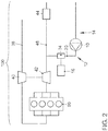
- FIG. 1 From a fresh gas line 38 air comes through the compressor 40 of the exhaust gas turbocharger via the intake manifold in the engine block 90. From the engine block 90, the exhaust gas passes through the turbine 42 of the exhaust gas turbocharger in the exhaust line 48th In the exhaust line 48, at least one catalyst 44 and / or at least one particle filter may be arranged. Downstream of the turbine 42, a secondary air line 20 opens into the exhaust line 48.
- the secondary air line 20 can in particular open into the exhaust line 48 between the at least one catalytic converter 44 and the turbine 42. According to the invention, the secondary air line 20 can open at any point in the exhaust line 48.
- the secondary air line 20 is divided by a secondary air pump 10 into two sides.
- a delivery side 12 and a suction side 14 are the two sides of the secondary air line 20.
- the delivery side 12 of the secondary air line 20 is the side which is conveyed through by the secondary air pump 10 with air.
- the delivery side 12 is thus the side downstream of the secondary air pump 10.
- the suction side 14 is the side which is used by the secondary air pump 10 to suck air.
- the suction side 14 is thus the side upstream of the secondary air pump 10.
- the brake booster 16 has arranged the brake booster 16 on the suction side 14.
- the brake booster 16 can be acted upon from the suction side 14 by the secondary air pump 10 with a negative pressure. This is particularly preferably done in a device according to the invention on the negative pressure side of the brake booster 16.
- FIG. 2 shows an internal combustion engine 100 with a device according to the invention.
- a fresh gas train 38 air comes through the compressor 40 of the exhaust gas turbocharger via the intake manifold in the engine block 90.
- the exhaust gas passes through the turbine 42 of the exhaust gas turbocharger in the exhaust line 48.
- the turbine 42 of the exhaust gas turbocharger in the exhaust line 48 is at least one catalyst 44 and / or arranged at least one particle filter.
- a secondary air line 20 opens into the exhaust line 48.
- the secondary air line 20 can in particular open into the exhaust line 48 between the at least one catalytic converter 44 and the turbine 42. According to the invention, the secondary air line 20 can open at any point in the exhaust line 48.
- the secondary air line 20 is divided by a secondary air pump 10 into two sides.
- a delivery side 12 and a suction side 14 are the two sides of the secondary air line 20.
- the delivery side of the secondary air line 20 is the side which is conveyed through by the secondary air pump 10 with air.
- the delivery side 12 is thus the side downstream of the secondary air pump 10.
- the suction side 14 is the side which is used by the secondary air pump 10 to suck air.
- the suction side 14 is thus the side upstream of the secondary air pump 10.
- a T-piece is formed as a Venturi tube 34. This Venturi tube 34 establishes the connection between a brake booster 16 and the secondary air line 20 on the delivery side 12.
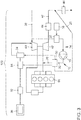
- the FIG. 3 shows a preferred embodiment of the internal combustion engine 100 according to the invention with a secondary air pump 10.
- the internal combustion engine 100 includes a fresh gas train 38, an engine block 90 and an exhaust line 48.
- the fresh gas train 38 may comprise an air filter and is equipped with a compressor 40 of an exhaust gas turbocharger.
- Located between the compressor 40 and the engine block 90 downstream of the compressor 40 is a throttle on the fresh gas train 38. Downstream of the throttle is an intake manifold which divides the fresh gas train 38 into the individual combustion chambers of the engine block 90.
- the exhaust gas is combined at the exit from the engine block 90 from an exhaust manifold in the exhaust line 48.
- the exhaust line 48 leads downstream of the exhaust manifold through the turbine 42 of the exhaust gas turbocharger.
- a catalyst 44 is arranged on the exhaust line 48.
- a catalyst 44 may generally be any exhaust treatment component that at least partially converts an ingredient of the exhaust into another substance.
- the catalyst 44 can be installed close to the engine or remote from the engine. Installed remotely are components of an exhaust system, which are located in the underbody of a vehicle with an internal combustion engine according to the invention.
- the catalyst 44 may be located downstream or upstream of a turbine 42 in the exhaust line. Downstream of the catalyst 44, a particulate filter 46 is arranged downstream of the catalyst 44.
- a particulate filter 46 here describes a component in an exhaust line 48, which was installed for the purpose of reducing a particle concentration in the exhaust stream downstream of a particulate filter 44 against a particulate concentration in the exhaust stream upstream of a particulate filter 44.
- the particulate filter 44 may, in particular, be a gasoline particulate filter or a diesel particulate filter.
- Ottoparticle filters differ from diesel particulate filters, for example, in the structural nature of the substrate for filtering and in the coatings of the substrate for filtering.
- One of the reasons for this difference is that the particles in the exhaust gas of gasoline engines have a different structure and, as a rule, have a smaller diameter than the particles in the exhaust gas of diesel engines.
- the internal combustion engine 100 comprises not only the aforementioned structures but also a conduit system for blowing in air.
- the piping system is part of the engine 100 to improve its operation.
- a secondary air line 20 branches off to a secondary air pump 10.
- the secondary air pump 10 may convey a controllable air mass flow or convey only a certain mass air flow. This has the advantage that the air mass of the pump control or controllable valves can be determined.
- the secondary air line 20 also constitutes a fluid connection between the secondary air pump 10 and the fresh gas line 38. A preferred arrangement is that this fluid connection branches off downstream of an air filter of the fresh gas line 38, since the air filter advantageously filters the air for several components.
- the secondary air pump 10 may introduce an air flow into a secondary air duct 20 and the other parts thereof.
- the secondary air line 20 downstream of the secondary air pump 10 is the delivery side 12.
- Die Secondary air line upstream of the secondary air pump 10 is the suction side 14.
- a 3/2-way valve 52 is arranged on the suction side 14 of the secondary air line.
- a brake booster 16 is arranged at the other path of the 3/2-way valve 52.
- the brake booster 16 may preferably be fluidically connected to the negative pressure side of the brake booster 16 with the 3/2-way valve 52.
- the brake booster 16 can also be fluidically connected to the X / Y valve 54 and thus have a connection to the delivery side 12 of the secondary air line 20.
- An X / Y valve 54 may according to the invention be a 3/2-way valve or another valve which can selectively switch between the 3 connections of the valve.
- the air flow of the secondary air line 10 is distributed and controllable between the possible secondary air lines 20 with a 5/2-way valve 50.
- the 5/2-way valve 50 can either continuously distribute the air flow between the connected lines or selectively always only one line to control.
- the 5/2-way valve 50 can be controlled and distributed in an advantageous manner, the air flow of the secondary air pump 10.
- the secondary air line 20 leads to the exhaust line 48 to a point upstream of the particulate filter 46 and opens at this point in the exhaust line 48.
- an air flow for regenerating the particulate filter 46 are introduced into the exhaust line 48.
- the particulate filter 46 can be regenerated in an advantageous manner, without a motor adjustment takes place in order to convey more oxygen into the exhaust line 48.
- with the 5/2-way valve 50 and the other parts of the secondary air line 20 can be acted upon by an air flow of the secondary air pump 10.
- These further parts of the secondary air line 20 open, inter alia upstream of the catalyst 44 in the exhaust line 48.
- a catalyst 44 can be heated particularly advantageous.
- the 5/2-way valve 50 is also fluidly connected to another part of the secondary air line 20. This part extends to the fresh gas line 38 and flows into the fresh gas line 38 or the compressor 40 immediately before the compressor 40.
- this part of the secondary air line 20 is arranged as a Venturi tube 34. From this tee as Venturi tube 34 is a branch off. The branch connects to a fuel vapor tank 32.
- the fuel vapor tank 32 is fluidly connected to the fuel tank 36 of the engine 100.
- the venturi 34 which may be designed in particular as a venturi, the container for fuel vapors 32 subjected to a negative pressure.
- the fuel vapors are thus drawn from the fuel vapor tank 32, the branch and the fuel tank 36.
- the fuel vapors are then conveyed into the fresh gas train 38 along with the airflow.
- Discharging the fuel vapors from the fuel vapor tank 32 is particularly advantageous when the fuel vapors are reversibly adsorbed in an activated carbon filter.
- the activated carbon filter may in particular be arranged in the container for fuel vapors 32.
- the FIG. 4 shows a schematic of an embodiment of a method according to the invention.
- a first step 1 the internal combustion engine 100 of a vehicle is started.
- the second step 2 the vehicle goes into driving.
- the pressure in a brake booster is checked.
- the pressure may preferably be determined stationarily with a single measurement or with several measurements over a time course. It is crucial that certain limits are met (these values can be stored for example in the control unit of the internal combustion engine). Should the pressure or vacuum in the brake booster need to be changed, the following can be done in the eighth step 8.
- the secondary air pump is activated to change the vacuum in the brake booster.
- the pressure in the brake booster always changes in both chambers.
- the eighth step 8 is executed until the corresponding pressure is set. If it should be determined in the fourth step 4 that the pressure in the brake booster is in order, at least the following benefits of the secondary air pump 10 can be carried out according to the invention.
- secondary air can be blown into the exhaust gas system. So can be regenerated with the secondary air, a gasoline filter. So can be regenerated with the secondary air and a catalyst.
- an exhaust system can be heated. All this is done by the increased oxygen content of the exhaust gas through the secondary air.
- the air flow of the secondary air pump can also be used to use the seal of the fuel tank system.
- the system of the fuel tank can contain a fuel tank, various lines, fuel pumps and / or adsorption devices.
- Adsorbtions facilities can be activated carbon filter or any other device that can bind reversible fuel and / or fuel vapors.
Abstract
Description
- Die Erfindung betrifft eine Brennkraftmaschine mit einer Sekundärluftpumpe gemäß dem Oberbegriff des Anspruchs 1. Darüber hinaus betrifft die Erfindung ein Verfahren zum Betreiben einer Brennkraftmaschine mit einer Sekundärluftpumpe gemäß dem Oberbegriff des Anspruchs 6.
- Durch Brennkraftmaschinen und deren Betrieb werden unerwünschte Verbrennungsprodukte, Partikel und Materialdämpfe in die Umwelt abgegeben. Diese Emissionen werden durch Gesetze auf Grenzwerte eingeschränkt. Um die Grenzwerte einzuhalten gelangen unter anderem Vorrichtungen zur Abgasbehandlung zum Einsatz. Wobei die Abgasbehandlungen häufig durch Sekundärluftpumpen unterstützt werden müssen.
- Aus der
DE 10 2004 001 831 B4 ist eine Abgasbehandlung mit einer Sekundärlufteinblasvorrichtung zum Aufheizen eines katalytischen Konverters bekannt. Diese Vorrichtung berücksichtigt bei der Steuerung der Sekundärlufteinblasvorrichtung den aktuellen Motorbetriebszustand und die aktuellen Abgasparameter. - Aus der
DE 10 2009 019 367 A1 ist eine Leckdiagnose eines Bremsverstärkersystems bekannt. Dazu wird der Bremsverstärkerunterdruck bezüglich seiner Abfallrate betrachtet. Ein ausreichender Unterdruck des Bremskraftverstärkers kann hier mit einem Motorunterdruck durch den elektrischen Motor eines Hybridfahrzeugs aufrecht erhalten werden. - Aufgabe der vorliegenden Erfindung ist es, eine Sekundärluftpumpe für mehrere Funktionen in einer Brennkraftmaschine zu nutzen.
- Diese Aufgabe wird erfindungsgemäß durch eine Brennkraftmaschine mit einer Sekundärluftpumpe mit den Merkmalen gemäß dem Anspruch 1 gelöst, sowie durch das Verfahren zum Betreiben einer Brennkraftmaschine mit einer Sekundärluftpumpe nach Anspruch 6. Vorteilhafte Weiterbildungen der Erfindung sind in den abhängigen Ansprüchen charakterisiert.
- Die Aufgabe wird durch eine Brennkraftmaschine mit einer Sekundärluftpumpe, mit einem Abgasstrang und mit einer Sekundärluftleitung ausgestattet. Dabei ist eine Verbindung zwischen der Förderseite der Sekundärluftpumpe und dem Abgasstrang mit der Sekundärluftleitung dargestellt. Außerdem ist eine Unterdruckseite eines Bremskraftverstärkers mit der Sekundärluftpumpe fluidisch verbunden.
- Diese Anordnung hat den Vorteil, dass die Unterdruckseite des Bremskraftverstärkers mit der Sekundärluftpumpe eine Druckveränderung erfahren kann. Somit ist es möglich die Sekundärluftpumpe nicht nur für die Unterstützung der Abgasnachbehandlung zu nutzen. Eine Sekundärluftpumpe umfasst eine Pumpe, die Luft in den Abgasstrang fördern kann und so eine Sekundäre Luftquelle darstellt. Eine Sekundärluftpumpe saugt ein Volumen von einer Saugseite und fördert dies Volumen zu einer Förderseite. Auf der Förderseite herrscht somit ein höherer Druck als auf der Saugseite. Die Unterdruckseite des Bremskraftverstärkers umfasst die Seite des räumlich in zwei Seiten aufgeteilten Bremskraftverstärkers, die zur Verstärkung der Bremswirkung mit einem Unterdruck beaufschlagt wird. Eine fluidische Verbindung umfasst eine Verbindung von einem Ort zu einem anderen Ort, bei der eine Flüssigkeit oder ein Gas von einem Ort zum anderen Ort fließen kann. Eine Betrachtung von speziellen Druckbeschaffenheiten an den Orten wird dabei nicht berücksichtigt. Eine fluidische Verbindung ist somit schon ein möglicher Weg von A nach B über eine gegebene Passage.
- In einer Ausgestaltung der Erfindung kann die Unterdruckseite des Bremskraftverstärkers mit einer Saugseite der Sekundärluftpumpe fluidisch verbunden sein.
- Diese Ausgestaltung hat den Vorteil, dass die Saugleistung der Sekundärluftpumpe der Saugleistung an der Unterdruckseite des Bremskraftverstärkers entspricht.
- In einer zusätzlichen Ausführung der Erfindung kann die Unterdruckseite des Bremskraftverstärkers mit einer Förderseite der Sekundärluftpumpe fluidisch verbunden sein.
- Diese Ausführung hat den Vorteil, dass ein Unterdruck an der Unterdruckseite des Bremskraftverstärkers indirekt erzeugt werden kann, zum Beispiel mit einem Venturi-Rohr. Die Leistung an der Unterdruckseite muss somit nicht der Leistung der Sekundärluftpumpe entsprechen.
- In einer bevorzugten Ausgestaltung der Erfindung kann die fluidische Verbindung von der Unterdruckseite des Bremskraftverstärkers zur Saugseite der Sekundärluftpumpe mit einem ansteuerbaren Ventil schaltbar sein.
- Ein Ventil umfasst eine Vorrichtung, die einen Fluidstrom in einer Leitung oder einer Verbindungsstelle regeln oder abstellen kann. Diese Regelung kann stufenlos oder in stufen erfolgen. Schaltbar umfasst, dass etwas bewusst verändert werden kann. Zum Beispiel kann ein Ansteuergerät ein Ventil mit elektrischen Signalen in verschiedene Zustände versetzen und so schalten. Ansteuerbar umfasst, dass ein Gerät mir elektrischen Signalen erreichbar ist. Das Gerät ist in diesem Fall ausgelegt, um elektrische Signale zu empfangen und zu verstehen. Diese Ausgestaltung hat den Vorteil, dass die Verbindung zu der Unterdruckseite des Bremskraftverstärkers regelbar ist. Es kann ein Steuergerät genutzt werden, um die Steuerung der Brennkraftmaschine mit der des Ventils zu koppeln und/oder abzustimmen. So kann auch eine vorausschätzende Steuerung eingestellt werden, die zukünftig wahrscheinliche Ereignisse auf Basis des geschehenden und geschehenen antizipiert.
- In einer Ausgestaltung der Erfindung kann ein Venturi-Rohr auf der Verbindung von der Unterdruckseite des Bremskraftverstärkers zu der Förderseite der Sekundärluftpumpe angeordnet sein.
- Diese Ausgestaltung hat den Vorteil, dass eine Beaufschlagung der Unterdruckseite des Bremskraftverstärkers mit einem Unterdruck so sehr bauteilarm und kostengünstig konstruiert werden kann. Ein Venturi-Rohr kann jede Form Von T-Stück einer Rohrleitung umfassen, bei dem an einer ersten Seite durch einen Fluidstrom in den übrigen Seiten ein Unterdruck entsteht.
- Das erfindungsgemäße Verfahren zum Betreiben einer Brennkraftmaschine mit einer Sekundärluftpumpe und mit einer Sekundärluftleitung umfasst folgende Handlungen. In dem Verfahren fördert die Sekundärluftpumpe ein Volumen von einer Saugseite der Sekundärluftpumpe zu einer Förderseite der Sekundärluftpumpe. Diese Volumenförderung der Sekundärluftpumpe wird genutzt, um den Druck im Bremskraftverstärker zu ändern.
- Das erfindungsgemäße Verfahren hat den Vorteil, dass mit dem Fördern Sekundärluftpumpe neben dem Hauptgrund für das Fördern ebenfalls der Bremskraftverstärker beeinflusst werden kann. Es kann aber auch nur der Bremskraftverstärker mit dem Fördern beeinflusst werden. Ein Volumen umfasst dabei eine räumliche Einheit die mit einem Fluid gefüllt ist und nicht physisch abgetrennt ist sondern beliebig in einem dreidimensionalen Raum eingeteilt werden kann.
- In einer Ausgestaltung des erfindungsgemäßen Verfahrens kann ein Volumen aus dem Bremskraftverstärker zur Saugseite der Sekundärluftpumpe gesaugt werden.
- Diese Ausgestaltung hat eine Unterdruckerzeugung im Bremskraftverstärker zum Vorteil, die ein direktes Aussaugen des Bremskraftverstärkers ermöglicht. Durch die Druckreduzierung kann auf vorteilhafte weise der Druck im Bremskraftverstärker reduziert werden und zum Beispiel eine Diagnose des Druckverlaufs über die Zeit geschehen. Mit dieser Beobachtung des Drucks kann so auf ein Leck des Bremskraftverstärker oder eine Fehlfunktion geschlossen werden. Diese Diagnose kann nur mit einer Auftragung des Drucks gegen die Zeit erfolgen. Bei einem untypischen Verlauf kann über eine Steuergerät eine Fehlermeldung in die Fahrerkabine eines Kraftfahrzeugs ausgegeben werden und so den Fahrer vor einer Gefahr durch ein verändertes Bremsverhalten zu warnen oder ein Fahren des Autos zu unterbinden.
- In einer Ausführungsform des erfindungsgemäßen Verfahrens ist es vorgesehen, dass ein Volumen aus dem Bremskraftverstärker durch ein Venturi-Rohr zur Förderseite der Sekundärluftpumpe gesaugt werden kann.
- Durch diese Ausführungsform kann auf vorteilhafte Weise ein Unterdruck in dem Bremskraftverstärker erzeugt werden. Der Aufbau dieses Unterdrucks ist abhängig von der Leistung der Volumenförderung der Sekundärluftpumpe in die Sekundärluftleitung und im Detail dem Abschnitt mit dem Venturi-Rohr. Die Dimensionierung des Venturi-Rohrs bestimmt im Wesentlichen dessen Saugwirkung, wenn ein Massenstrom durch die Hauptleitung führt. Somit kann für dieses Verfahren auf vorteilhafte Weise eine Regelung durch eine Auslegung des Bauteils ersetzt werden.
- In einer bevorzugten Ausgestaltung des Erfindungsgemäßen Verfahrens kann ein Gasvolumen von der Förderseite der Sekundärluftpumpe in den Bremskraftverstärker gefördert werden. So kann der Druck im Bremskraftverstärker erhöht werden.
- Dies führt auf vorteilhafte Weise zu einer weiteren Möglichkeit zur Drucküberwachung des Bremskraftverstärkers.
- Eine weitere Ausgestaltung des erfindungsgemäßen Verfahrens kann der Druck im Bremskraftverstärker gegen die Zeit aufgetragen und überwacht werden.
- Diese Ausgestaltung hat zum Vorteil, dass diese Auftragung und die Überwachung je für sich zu einer Diagnose und Überwachungsmöglichkeit führen. Eine Überwachungsmöglichkeit und überwachen kann zum Beispiel meinen, dass ein Steuergerät oder eine Recheneinheit die gemessenen Werte, Kurven und Änderungen mit Referenzen und/oder Grenzwerten vergleicht und bei einer zu Hohen Abweichung ein Fehler-, Diagnose- oder Warnprotokoll durchführt.
- Weitere Vorteile und vorteilhafte Ausführungsformen und Weiterbildungen der Erfindung werden anhand der nachfolgenden Beschreibung unter Bezugnahme auf die Figuren dargestellt. Es zeigt im Einzelnen:
- Figur 1
- eine bevorzugte Ausführungsform der erfindungsgemäßen Brennkraftmaschine mit einer Sekundärluftpumpe,
- Figur 2
- eine weitere bevorzugte Ausführungsform der erfindungsgemäßen Brennkraftmaschine mit einer Sekundärluftpumpe,
- Figur 3
- eine weitere bevorzugte Ausführungsform der erfindungsgemäßen Brennkraftmaschine mit einer Sekundärluftpumpe, und
- Figur 4
- ein bevorzugtes Ausführungsschema des erfindungsgemäßen Verfahrens zum Betreiben einer Brennkraftmaschine mit einer Sekundärluftpumpe.
- Die
Figur 1 zeigt eine bevorzugte Ausführungsform der erfindungsgemäßen Brennkraftmaschine 100 mit einer Sekundärluftpumpe 10. Von einem Frischgasstrang 38 kommt Luft durch den Verdichter 40 des Abgasturboladers über den Einlasskrümmer in den Motorblock 90. Aus dem Motorblock 90 gelangt das Abgas durch die Turbine 42 des Abgasturboladers in den Abgasstrang 48. In dem Abgasstrang 48 kann mindestens ein Katalysator 44 und/oder mindestens ein Partikelfilter angeordnet sein. Stromab der Turbine 42 mündet eine Sekundärluftleitung 20 in den Abgasstrang 48. Die Sekundärluftleitung 20 kann insbesondere zwischen dem mindestens einen Katalysator 44 und der Turbine 42 in den Abgasstrang 48 einmünden. Erfindungsgemäß kann die Sekundärluftleitung 20 an einer beliebigen Stelle in den Abgasstrang 48 münden. Bevorzugte Stellen können im Abgaskrümmer nach dem Motorblock 90 sein, unmittelbar vor oder nach der Turbine 42 und/oder vor einem Bauteil zur Abgasbehandlung (dies kann beispielsweise ein Katalysator 44 und/oder ein Partikelfilter sein). Die Sekundärluftleitung 20 wird durch eine Sekundärluftpumpe 10 in zwei Seiten unterteilt. Eine Förderseite 12 und eine Saugseite 14 sind die zwei Seiten der Sekundärluftleitung 20. Die Förderseite 12 der Sekundärluftleitung 20 ist dabei die Seite, die von der Sekundärluftpumpe 10 mit Luft durchfördert wird. Die Förderseite 12 ist somit die Seite stromab der Sekundärluftpumpe 10. Die Saugseite 14 ist die Seite, die von der Sekundärluftpumpe 10 genutzt wird, um Luft anzusaugen. Die Saugseite 14 ist somit die Seite stromauf der Sekundärluftpumpe 10. Die erfindungsgemäße Ausführungsform inFigur 1 hat auf der Saugseite 14 den Bremskraftverstärker 16 angeordnet. Dadurch kann der Bremskraftverstärker 16 von der Saugseite 14 her durch die Sekundärluftpumpe 10 mit einem Unterdruck beaufschlagt werden. Besonders bevorzugt geschieht dies bei einer erfindungsgemäßen Vorrichtung an der Unterdruckseite des Bremskraftverstärkers 16. -
Figur 2 zeigt eine Brennkraftmaschine 100 mit einer erfindungsgemäßen Vorrichtung. Von einem Frischgasstrang 38 kommt Luft durch den Verdichter 40 des Abgasturboladers über den Einlasskrümmer in den Motorblock 90. Aus dem Motorblock 90 gelangt das Abgas durch die Turbine 42 des Abgasturboladers in den Abgasstrang 48. In dem Abgasstrang 48 ist mindestens ein Katalysator 44 und/oder mindestens ein Partikelfilter angeordnet. Stromab der Turbine 42 mündet eine Sekundärluftleitung 20 in den Abgasstrang 48. Die Sekundärluftleitung 20 kann insbesondere zwischen dem mindestens einen Katalysator 44 und der Turbine 42 in den Abgasstrang 48 einmünden. Erfindungsgemäß kann die Sekundärluftleitung 20 an einer beliebigen Stelle in den Abgasstrang 48 münden. Bevorzugte Stellen können im Abgaskrümmer nach dem Motorblock 90 sein, unmittelbar vor oder nach der Turbine 42 und/oder vor einem Bauteil zur Abgasbehandlung (dies kann beispielsweise ein Katalysator 44 und/oder ein Partikelfilter sein). Die Sekundärluftleitung 20 wird durch eine Sekundärluftpumpe 10 in zwei Seiten unterteilt. Eine Förderseite 12 und eine Saugseite 14 sind die zwei Seiten der Sekundärluftleitung 20. Die Förderseite der Sekundärluftleitung 20 ist dabei die Seite, die von der Sekundärluftpumpe 10 mit Luft durchfördert wird. Die Förderseite 12 ist somit die Seite stromab der Sekundärluftpumpe 10. Die Saugseite 14 ist die Seite, die von der Sekundärluftpumpe 10 genutzt wird, um Luft anzusaugen. Die Saugseite 14 ist somit die Seite stromauf der Sekundärluftpumpe 10. Auf der Förderseite 12 der Sekundärluftleitung 20 ist ein T-Stück als Venturi-Rohr 34 ausgebildet. Diese Venturi-Rohr 34 stellt die Verbindung zwischen einem Bremskraftverstärker 16 und der Sekundärluftleitung 20 auf der Förderseite 12 her. - Die
Figur 3 zeigt eine bevorzugte Ausführungsform der erfindungsgemäßen Brennkraftmaschine 100 mit einer Sekundärluftpumpe 10. Die Brennkraftmaschine 100 umfasst einen Frischgasstrang 38, einen Motorblock 90 und einen Abgasstrang 48. Der Frischgasstrang 38 kann einen Luftfilter umfassen und ist mit einem Verdichter 40 eines Abgasturboladers ausgestattet. Zwischen dem Verdichter 40 und dem Motorblock 90 befindet sich stromab des Verdichters 40 eine Drosselklappe auf dem Frischgasstrang 38. Stromab der Drosselklappe befindet sich ein Einlasskrümmer, der den Frischgasstrang 38 in die einzelnen Brennkammern des Motorblocks 90 aufteilt. Das Abgas wird bei Austritt aus dem Motorblock 90 von einem Abgaskrümmer in den Abgasstrang 48 zusammengeführt. Der Abgasstrang 48 führt stromab des Abgaskrümmers durch die Turbine 42 des Abgasturboladers. Nach der Turbine 42 ist auf dem Abgasstrang 48 ein Katalysator 44 angeordnet. Ein Katalysator 44 kann allgemein jede Abgasbehandlungskomponente sein, die einen Inhaltsstoff des Abgases zumindest teilweise in einen anderen Stoff umwandelt. Der Katalysator 44 kann motornah oder motorfern verbaut werden. Motorfern verbaut sind Bauteile einer Abgasanlage, welche sich im Unterboden eines Fahrzeugs mit einer erfindungsgemäßen Brennkraftmaschine befinden. Der Katalysator 44 kann stromab oder stromauf einer Turbine 42 im Abgasstrang angeordnet sein. Stromab des Katalysators 44 ist ein Partikelfilter 46 angeordnet. Ein Partikelfilter 46 beschreibt hier ein Bauteil in einem Abgasstrang 48, das zu dem Zweck eingebaut wurde, eine Partikelkonzentration im Abgasstrom stromab eines Partikelfilters 44 gegenüber einer Partikelkonzentration im Abgasstrom stromauf eines Partikelfilters 44 zu reduzieren. Der Partikelfilter 44 kann insbesondere ein Ottopartikelfilter oder ein Dieselpartikelfilter sein. Ottopartikelfilter unterscheiden sich von Dieselpartikelfiltern zum Beispiel in der strukturellen Beschaffenheit des Substrats zum Filtern und hinsichtlich der Beschichtungen des Substrats zum Filtern. Dieser Unterschied ist unter anderem darin begründet, dass die Partikel im Abgas von Ottomotoren eine andere Struktur haben und in der Regel einen geringeren Durchmesser haben, als die Partikel im Abgas von Dieselmotoren. Die Brennkraftmaschine 100 umfasst neben den vorgenannten Strukturen auch ein Leitungssystem zum Einblasen von Luft. Das Leitungssystem ist Teil der Brennkraftmaschine 100, um deren Betrieb zu verbessern. Vom Frischgasstrang 38 zweigt eine Sekundärluftleitung 20 zu einer Sekundärluftpumpe 10 ab. Die Sekundärluftpumpe 10 kann einen regelbaren Luftmassenstrom befördern oder nur einen bestimmten Luftmassenstrom befördern. Dies hat den Vorteil dass die Luftmasse von der Pumpensteuerung oder von regelbaren Ventilen bestimmt werden kann. Die Sekundärluftleitung 20 stellt auch eine Fluidverbindung zwischen der Sekundärluftpumpe 10 und dem Frischgasstrang 38 dar. Dabei ist eine bevorzugte Anordnung, dass diese Fluidverbindung stromab eines Luftfilters des Frischgasstrangs 38 abzweigt, da so auf vorteilhafte Weise der Luftfilter für mehrere Bauteile die Luft filtriert. Die Sekundärluftpumpe 10 kann einen Luftstrom in eine Sekundärluftleitung 20 und deren andere Teile einbringen. Die Sekundärluftleitung 20 stromab der Sekundärluftpumpe 10 ist die Förderseite 12. Die Sekundärluftleitung stromauf der Sekundärluftpumpe 10 ist die Saugseite 14. Auf der Saugseite 14 der Sekundärluftleitung ist ein 3/2-Wege-Ventil 52 angeordnet. An dem anderen Pfad des 3/2-Wege-Ventils 52 ist ein Bremskraftverstärker 16 angeordnet. Der Bremskraftverstärker 16 kann bevorzugt mit der Unterdruckseite des Bremskraftverstärkers 16 mit dem 3/2-Wege-Ventil 52 fluidisch verbunden sein. In einer bevorzugten Variante der erfindungsgemäßen Vorrichtung kann der Bremskraftverstärker 16 auch mit dem X/Y Ventil 54 fluidisch verbunden sein und so eine Verbindung zur Förderseite 12 der Sekundärluftleitung 20 aufweisen. Ein X/Y-Ventil 54 kann erfindungsgemäß eine 3/2-Wege-Ventil sein oder ein anderes Ventil das selektiv zwischen den 3 Verbindungen des Ventils schalten kann. Der Luftstrom der Sekundärluftleitung 10 ist zwischen den möglichen Sekundärluftleitungen 20 mit einem 5/2-Wege-Ventil 50 verteilbar und steuerbar. Das 5/2-Wege-Ventil 50 kann dabei den Luftstrom entweder stufenlos zwischen den angeschlossenen Leitungen verteilen oder wahlweise immer nur eine Leitung ansteuern. Durch das 5/2-Wege-Ventil 50 kann so auf vorteilhafte Weise der Luftstrom der Sekundärluftpumpe 10 gesteuert und verteilt werden. In dieser Ausführungsform der Erfindung führt vom 5/2-WegeVentil 50 die Sekundärluftleitung 20 zum Abgasstrang 48 zu einer Stelle Stromauf des Partikelfilters 46 und mündet an dieser Stelle in den Abgasstrang 48. So kann mit Hilfe der Sekundärluftleitung 20 in Verbindung mit der Sekundärluftpumpe 10 und dem 5/2-Wege-Ventil 50 ein Luftstrom zum Regenerieren des Partikelfilters 46 in den Abgasstrang 48 eingebracht werden. So kann der Partikelfilter 46 auf vorteilhafte Weise regeneriert werden, ohne dass eine motorische Verstellung erfolgt, um mehr Sauerstoff in den Abgasstrang 48 zu befördern. In dieser Ausführungsform der Erfindung können mit dem 5/2-Wege-Ventil 50 auch die weiteren Teile der Sekundärluftleitung 20 mit einem Luftstrom der Sekundärluftpumpe 10 beaufschlagt werden. Diese weiteren Teile der Sekundärluftleitung 20 münden unter anderem stromauf des Katalysators 44 in den Abgasstrang 48. Mit einem Luftstrom durch die weiteren Teile der Sekundärluftleitung 20 kann besonders vorteilhaft ein Katalysator 44 aufgeheizt werden. Eine exotherme Reaktion zwischen brennbaren Inhaltsstoffen der Abgase und dem Sauerstoff des eingebrachten Luftstroms liefert so die Energie zum Heizen des Katalysators 44, mit einem Vorteil gegenüber einer Verstellung des Motors zur Bereitstellung dieser Hitze. Das 5/2-WegeVentil 50 ist auch mit einem weiteren Teil der Sekundärluftleitung 20 fluidisch verbunden. Dieser Teil erstreckt sich bis zum Frischgasstrang 38 und mündet unmittelbar vor dem Verdichter 40 in den Frischgasstrang 38 oder in den Verdichter 40. In dieser erfindungsgemäßen Ausführungsform ist diesem Teil der Sekundärluftleitung 20 ein T-Stück als Venturi-Rohr 34 angeordnet. Von diesem T-Stück als Venturi-Rohr 34 geht ein Abzweig ab. Der Abzweig schafft eine Verbindung mit einem Behälter für Kraftstoffdämpfe 32. Dabei ist der Behälter für Kraftstoffdämpfe 32 fluidisch mit dem Kraftstofftank 36 der Brennkraftmaschine 100 verbunden. Wenn ein Luftstrom durch diesen Teil der Sekundärluftleitung fließt, so wird durch das Venturi-Rohr 34, das insbesondere als Venturidüse ausgeführt sein kann, der Behälter für Kraftstoffdämpfe 32 mit einem Unterdruck beaufschlagt. Die Kraftstoffdämpfe werden so aus dem Behälter für Kraftstoffdämpfe 32, dem Abzweig und dem Kraftstofftank 36 gesogen. Die Kraftstoffdämpfe werden im Anschluss zusammen mit dem Luftstrom in den Frischgasstrang 38 befördert. Das Austragen der Kraftstoffdämpfe aus dem Behälter für Kraftstoffdämpfe 32 ist besonders vorteilhaft, wenn die Kraftstoffdämpfe reversibel in einem Aktivkohlefilter adsorbiert werden. Der Aktivkohlefilter kann insbesondere in dem Behälter für Kraftstoffdämpfe 32 angeordnet sein. - Die
Figur 4 zeigt ein Schema einer Ausführungsform eines erfindungsgemäßen Verfahrens. In einem ersten Schritt 1 wird die Brennkraftmaschine 100 eines Fahrzeuges gestartet. Im zweiten Schritt 2 geht das Fahrzeug in den Fahrbetrieb über. Im dritten Schritt 3 wird der Druck in einem Bremskraftverstärker überprüft. Der Druck kann bevorzugt stationär mit einer einzelnen Messung oder mit mehreren Messungen über einen Zeitverlauf bestimmt werden. Dabei ist entscheidend, dass bestimmte Grenzwerte eingehalten werden (diese Werte können beispielsweise im Steuergerät der Brennkraftmaschine hinterlegt sein). Sollte der Druck oder Unterdruck im Bremskraftverstärker geändert werden müssen, so kann im achten Schritt 8 folgendes geschehen. Die Sekundärluftpumpe wird aktiviert, um den Unterdruck im Bremskraftverstärker zu ändern. Der Druck im Bremskraftverstärker ändert sich dabei immer in beiden Kammern. Je nach Konstruktion der Vorrichtung müssen diverse Ventile geschaltet werden, um die Verringerung des Drucks im Bremskraftverstärker zu bewirken. Der achte Schritt 8 wird solange ausgeführt, bis der entsprechende Druck eingestellt ist. Sollte im vierten Schritt 4 festgestellt werden, dass der Druck im Bremskraftverstärker in Ordnung ist, so können erfindungsgemäß zumindest folgende Nutzen der Sekundärluftpumpe 10 durchgeführt werden. Zum einen kann Sekundärluft in den Abgasstrang eingeblasen werden. So kann mit der Sekundärluft ein Ottopartikelfilter regeneriert werden. So kann mit der Sekundärluft auch ein Katalysator regeneriert werden. So kann mit der Sekundärluft eine Abgasanlage geheizt werden. All dies geschieht durch den erhöhten Sauerstoffanteil des Abgases durch die Sekundärluft. Der Luftstrom der Sekundärluftpumpe kann auch genutzt werden, um die Abdichtung der Anlage des Kraftstofftanks zu benutzen. Dazu kann die Anlage des Kraftstofftanks einen Kraftstofftank, diverse Leitungen, Kraftstoffpumpen und/oder Adsorbtions-Einrichtungen enthalten. Adsorbtions-Einrichtungen können dabei Aktivkohlefilter sein oder jede andere Einrichtung, die Kraftstoff und/oder Kraftstoffdämpfe reversibel binden kann. -
- 1
- erster Schritt
- 2
- zweiter Schritt
- 3
- dritter Schritt
- 4
- vierter Schritt
- 5
- fünfter Schritt
- 10
- Sekundärluftpumpe
- 12
- Förderseite
- 14
- Saugseite
- 16
- Bremskraftverstärker
- 20
- Sekundärluftleitung
- 32
- Behälter für Kraftstoffdämpfe
- 34
- Venturi-Rohr
- 36
- Kraftstofftank
- 38
- Frischgasstrang
- 40
- Verdichter
- 42
- Turbine
- 44
- Katalysator
- 46
- Partikelfilter
- 48
- Abgasstrang
- 50
- 5/2-Wege-Ventil
- 52
- 3/2-Wege-Ventil
- 54
- Y/N-Ventil
- 90
- Motorblock
- 100
- Brennkraftmaschine
Claims (10)
- Brennkraftmaschine (100) mit einer Sekundärluftpumpe (10), mit einem Abgasstrang (48) und mit einer Sekundärluftleitung (20), die eine Verbindung zwischen der Förderseite (12) der Sekundärluftpumpe (10) und dem Abgasstrang (48) darstellt,
dadurch gekennzeichnet,
dass eine Unterdruckseite eines Bremskraftverstärkers (16) mit der Sekundärluftpumpe (10)fluidisch verbunden ist. - Brennkraftmaschine (100) mit einer Sekundärluftpumpe (10) nach Anspruch 1,
dadurch gekennzeichnet,
dass die Unterdruckseite des Bremskraftverstärkers (16) mit einer Saugseite (14) der Sekundärluftpumpe (10)fluidisch verbunden ist. - Brennkraftmaschine (100) mit einer Sekundärluftpumpe (10) nach Anspruch 1,
dadurch gekennzeichnet,
dass die Unterdruckseite des Bremskraftverstärkers (10) mit einer Förderseite (12) der Sekundärluftpumpe (10)fluidisch verbunden ist. - Brennkraftmaschine (100) mit einer Sekundärluftpumpe (10) nach Anspruch 3,
dadurch gekennzeichnet,
dass fluidische Verbindung von der Unterdruckseite des Bremskraftverstärkers (16) zu der Förderseite (12) der Sekundärluftpumpe (10) mit einem ansteuerbaren Ventil schaltbar ist. - Brennkraftmaschine (100) mit einer Sekundärluftpumpe (10) nach Anspruch 3,
dadurch gekennzeichnet,
dass ein Venturi-Rohr (34) auf der fluidischen Verbindung von der Unterdruckseite des Bremskraftverstärkers (16) zu der Förderseite (12) der Sekundärluftpumpe (10) angeordnet ist. - Verfahren zum Berteiben einer Brennkraftmaschine (100) mit einer Sekundärluftpumpe (10), mit einem Abgasstrang (48) und mit einer Sekundärluftleitung (20), wobei die Sekundärluftpumpe (10) ein Volumen von einer Saugseite (14) der Sekundärluftpumpe (10) zu einer Förderseite (12) der Sekundärluftpumpe (10) fördert,
dadurch gekennzeichnet,
dass die Volumenförderung der Sekundärluftpumpe (10) genutzt wird, um den Druck im Bremskraftverstärker (16) zu ändern. - Verfahren zum Betreiben einer Brennkraftmaschine (100) mit einer Sekundärluftpumpe (10) nach Anspruch 6,
dadurch gekennzeichnet,
dass ein Gasvolumen aus dem Bremskraftverstärker (16) zur Saugseite (14) der Sekundärluftpumpe (10) gesaugt wird. - Verfahren zum Betreiben einer Brennkraftmaschine (100) mit einer Sekundärluftpumpe (10) nach Anspruch 6,
dadurch gekennzeichnet,
dass ein Gasvolumen aus dem Bremskraftverstärker (16) durch ein Venturi-Rohr (34) zur Förderseite (12) der Sekundärluftpumpe (10) gesaugt wird. - Verfahren zum Betreiben einer Brennkraftmaschine (100) mit einer Sekundärluftpumpe (10) nach Anspruch 6,
dadurch gekennzeichnet,
dass ein Gasvolumen von der Förderseite (12) der Sekundärluftpumpe (10) in den Bremskraftverstärker (16) gefördert wird und so der Druck im Bremskraftverstärker (16) erhöht. - Verfahren zum Betreiben einer Brennkraftmaschine (100) mit einer Sekundärluftpumpe (10) nach Anspruch 8,
dadurch gekennzeichnet,
dass der Druck im Bremskraftverstärker (16) gegen die Zeit aufgetragen und überwacht wird.
Applications Claiming Priority (1)
| Application Number | Priority Date | Filing Date | Title |
|---|---|---|---|
| DE102017201716.3A DE102017201716A1 (de) | 2017-02-02 | 2017-02-02 | Brennkraftmaschine mit einer Sekundärluftpumpe und Verfahren zum Betreiben einer Brennkraftmaschine mit einer Sekundärluftpumpe |
Publications (2)
| Publication Number | Publication Date |
|---|---|
| EP3358160A1 true EP3358160A1 (de) | 2018-08-08 |
| EP3358160B1 EP3358160B1 (de) | 2019-12-25 |
Family
ID=61022176
Family Applications (1)
| Application Number | Title | Priority Date | Filing Date |
|---|---|---|---|
| EP18152684.9A Active EP3358160B1 (de) | 2017-02-02 | 2018-01-22 | Brennkraftmaschine mit einer sekundärluftpumpe und verfahren zum betreiben einer brennkraftmaschine mit einer sekundärluftpumpe |
Country Status (4)
| Country | Link |
|---|---|
| US (1) | US20180216561A1 (de) |
| EP (1) | EP3358160B1 (de) |
| CN (1) | CN108386257B (de) |
| DE (1) | DE102017201716A1 (de) |
Cited By (1)
| Publication number | Priority date | Publication date | Assignee | Title |
|---|---|---|---|---|
| FR3122699A1 (fr) * | 2021-05-05 | 2022-11-11 | Renault S.A.S | Moteur à combustion interne |
Families Citing this family (1)
| Publication number | Priority date | Publication date | Assignee | Title |
|---|---|---|---|---|
| EP3201451B1 (de) * | 2014-09-29 | 2020-03-18 | Boost Mechanics (Pty) Limited | Turbomaschinenanordnung für eine brennkraftmaschine mit venturi-vorrichtung |
Citations (5)
| Publication number | Priority date | Publication date | Assignee | Title |
|---|---|---|---|---|
| DE3926428A1 (de) * | 1989-08-10 | 1991-02-14 | Audi Ag | Vorrichtung zum versorgen von pneumatischen einrichtungen in kraftfahrzeugen |
| EP1367256A1 (de) * | 2002-05-14 | 2003-12-03 | Ford Global Technologies, Inc., A subsidiary of Ford Motor Company | Verfahren zur Vorbereitung des Anlassens einer Brennkraftmaschine |
| DE102006004768A1 (de) * | 2006-02-02 | 2007-05-03 | Audi Ag | Abgasnachbehandlungsvorrichtung für eine Verbrennungskraftmaschine eines Kraftfahrzeugs |
| DE102009019367A1 (de) * | 2008-05-02 | 2009-12-24 | GM Global Technology Operations, Inc., Detroit | Leckdiagnose für ein Bremsverstärkersystem |
| DE102013113228A1 (de) * | 2013-11-29 | 2015-06-03 | Dr. Ing. H.C. F. Porsche Aktiengesellschaft | Einrichtung zur Versorgung von Betriebskomponenten eines Kraftfahrzeugs mit Luft |
Family Cites Families (8)
| Publication number | Priority date | Publication date | Assignee | Title |
|---|---|---|---|---|
| US6802181B2 (en) | 2003-01-14 | 2004-10-12 | General Motors Corporation | Method and apparatus for monitoring catalyst efficiency and secondary air injection |
| EP1464799A1 (de) | 2003-03-31 | 2004-10-06 | Ford Global Technologies, LLC, A subsidary of Ford Motor Company | Verfahren zum Starten einer Brennkraftmaschine |
| CN102282352B (zh) * | 2009-02-02 | 2014-08-20 | 博格华纳公司 | 驱动装置 |
| DE102011083904A1 (de) * | 2011-09-30 | 2013-04-04 | Robert Bosch Gmbh | Verbrennungsanordnung mit einer Brennkraftmaschine und einem Abgaskanal sowie Verfahren zur Abgasnachbehandlung einer Brennkraftmaschine |
| US8839607B2 (en) * | 2012-12-13 | 2014-09-23 | Ford Global Technologies, Llc | Ejector in conjunction with post-catalyst exhaust throttle for vacuum generation |
| CN203383886U (zh) * | 2013-08-08 | 2014-01-08 | 安徽江淮汽车股份有限公司 | 一种发动机二次空气喷射装置 |
| US9267464B2 (en) * | 2014-04-30 | 2016-02-23 | Ford Global Technologies, Llc | Method and system for vacuum generation |
| DE102014209427B4 (de) | 2014-05-19 | 2016-12-22 | Aft Automotive Gmbh & Co. Kg | Unterdruckpumpenanordnung sowie Verfahren zum Herstellen einer Unterdruckpumpenanordnung |
-
2017
- 2017-02-02 DE DE102017201716.3A patent/DE102017201716A1/de not_active Withdrawn
-
2018
- 2018-01-22 EP EP18152684.9A patent/EP3358160B1/de active Active
- 2018-02-01 US US15/886,015 patent/US20180216561A1/en not_active Abandoned
- 2018-02-02 CN CN201810106174.4A patent/CN108386257B/zh active Active
Patent Citations (5)
| Publication number | Priority date | Publication date | Assignee | Title |
|---|---|---|---|---|
| DE3926428A1 (de) * | 1989-08-10 | 1991-02-14 | Audi Ag | Vorrichtung zum versorgen von pneumatischen einrichtungen in kraftfahrzeugen |
| EP1367256A1 (de) * | 2002-05-14 | 2003-12-03 | Ford Global Technologies, Inc., A subsidiary of Ford Motor Company | Verfahren zur Vorbereitung des Anlassens einer Brennkraftmaschine |
| DE102006004768A1 (de) * | 2006-02-02 | 2007-05-03 | Audi Ag | Abgasnachbehandlungsvorrichtung für eine Verbrennungskraftmaschine eines Kraftfahrzeugs |
| DE102009019367A1 (de) * | 2008-05-02 | 2009-12-24 | GM Global Technology Operations, Inc., Detroit | Leckdiagnose für ein Bremsverstärkersystem |
| DE102013113228A1 (de) * | 2013-11-29 | 2015-06-03 | Dr. Ing. H.C. F. Porsche Aktiengesellschaft | Einrichtung zur Versorgung von Betriebskomponenten eines Kraftfahrzeugs mit Luft |
Cited By (1)
| Publication number | Priority date | Publication date | Assignee | Title |
|---|---|---|---|---|
| FR3122699A1 (fr) * | 2021-05-05 | 2022-11-11 | Renault S.A.S | Moteur à combustion interne |
Also Published As
| Publication number | Publication date |
|---|---|
| US20180216561A1 (en) | 2018-08-02 |
| EP3358160B1 (de) | 2019-12-25 |
| CN108386257B (zh) | 2021-03-02 |
| CN108386257A (zh) | 2018-08-10 |
| DE102017201716A1 (de) | 2018-08-02 |
Similar Documents
| Publication | Publication Date | Title |
|---|---|---|
| EP2659121B1 (de) | Vorrichtung zum wahlweisen regenerieren oder durchführen einer tankleckdiagnose eines tankentlüftungssystems | |
| DE102011084539B3 (de) | Turbolader mit einer Venturidüse zur Entlüftung eines Aktivkohlefilters | |
| EP3622207B1 (de) | Ventilmodul | |
| DE112012005308T5 (de) | Turbo-Spülmodul für turboaufgeladene Fahrzeuge | |
| EP2122136B1 (de) | Abgasstrang für einen verbrennungsmotor | |
| DE102013109459B4 (de) | Tankentlüftungsvorrichtung | |
| DE102013111285B4 (de) | Bremsunterdruckerzeugungsvorrichtung für ein Fahrzeug | |
| EP3358160B1 (de) | Brennkraftmaschine mit einer sekundärluftpumpe und verfahren zum betreiben einer brennkraftmaschine mit einer sekundärluftpumpe | |
| DE102015111158A1 (de) | Motorsystem zum Steuern einer Strömung von Abgas | |
| DE102011076429A1 (de) | Dosiersystem und Verfahren zu seinem Betrieb | |
| DE102014211159A1 (de) | Vorrichtung zur katalytischen chemischen Umsetzungwenigstens einer Komponente eines Gasstromsund Abgasanlage für eine Brennkraftmaschine | |
| WO2011134893A1 (de) | Vorrichtung zur förderung von reduktionsmittel | |
| DE102014222632A1 (de) | Aktives Spülpumpensystemmodul für ein Verdampfungs-Emissionssteuersystem | |
| DE102018120443A1 (de) | Verfahren zur Tankentlüftung eines Fahrzeugs sowie eine Vorrichtung zur Tankentlüftung eines Fahrzeugs sowie ein Fahrzeug | |
| DE102008052763B4 (de) | Tankentlüftungseinrichtung für ein Kraftfahrzeug | |
| DE102007035355A1 (de) | Vorrichtung und Verfahren zur Behandlung von Blow-By-Gasen, insbesondere Kurbelgehäuse-Entlüftungsvorrichtung | |
| DE102004021387A1 (de) | Brennkraftmaschine | |
| EP2825762A1 (de) | Vorrichtung zum zusätzlichen verdichten der ladeluft einer brennkraftmaschine | |
| DE102016219774B4 (de) | System für ein Kraftfahrzeug und Verfahren zum Betreiben einer Brennkraftmaschine für ein Kraftfahrzeug | |
| WO2017108246A1 (de) | Verfahren zur regeneration eines aktivkohlefilters | |
| DE102016221901A1 (de) | Verfahren zur Steuerung einer Tankentlüftung für einen Kraftstofftank | |
| EP3874133A1 (de) | Verfahren zum betreiben einer abgasnachbehandlungseinrichtung | |
| DE102019101181A1 (de) | Verfahren zur Regeneration eines Aktivkohlefilters sowie Verbrennungsmotor | |
| DE10255801A1 (de) | Tankentlüftungseinrichtung für Kraftfahrzeuge | |
| DE102019121388A1 (de) | Einlasskrümmer |
Legal Events
| Date | Code | Title | Description |
|---|---|---|---|
| PUAI | Public reference made under article 153(3) epc to a published international application that has entered the european phase |
Free format text: ORIGINAL CODE: 0009012 |
|
| STAA | Information on the status of an ep patent application or granted ep patent |
Free format text: STATUS: THE APPLICATION HAS BEEN PUBLISHED |
|
| AK | Designated contracting states |
Kind code of ref document: A1 Designated state(s): AL AT BE BG CH CY CZ DE DK EE ES FI FR GB GR HR HU IE IS IT LI LT LU LV MC MK MT NL NO PL PT RO RS SE SI SK SM TR |
|
| AX | Request for extension of the european patent |
Extension state: BA ME |
|
| STAA | Information on the status of an ep patent application or granted ep patent |
Free format text: STATUS: REQUEST FOR EXAMINATION WAS MADE |
|
| 17P | Request for examination filed |
Effective date: 20190208 |
|
| RBV | Designated contracting states (corrected) |
Designated state(s): AL AT BE BG CH CY CZ DE DK EE ES FI FR GB GR HR HU IE IS IT LI LT LU LV MC MK MT NL NO PL PT RO RS SE SI SK SM TR |
|
| STAA | Information on the status of an ep patent application or granted ep patent |
Free format text: STATUS: EXAMINATION IS IN PROGRESS |
|
| 17Q | First examination report despatched |
Effective date: 20190502 |
|
| GRAP | Despatch of communication of intention to grant a patent |
Free format text: ORIGINAL CODE: EPIDOSNIGR1 |
|
| STAA | Information on the status of an ep patent application or granted ep patent |
Free format text: STATUS: GRANT OF PATENT IS INTENDED |
|
| INTG | Intention to grant announced |
Effective date: 20190924 |
|
| GRAS | Grant fee paid |
Free format text: ORIGINAL CODE: EPIDOSNIGR3 |
|
| GRAA | (expected) grant |
Free format text: ORIGINAL CODE: 0009210 |
|
| STAA | Information on the status of an ep patent application or granted ep patent |
Free format text: STATUS: THE PATENT HAS BEEN GRANTED |
|
| AK | Designated contracting states |
Kind code of ref document: B1 Designated state(s): AL AT BE BG CH CY CZ DE DK EE ES FI FR GB GR HR HU IE IS IT LI LT LU LV MC MK MT NL NO PL PT RO RS SE SI SK SM TR |
|
| REG | Reference to a national code |
Ref country code: GB Ref legal event code: FG4D Free format text: NOT ENGLISH |
|
| REG | Reference to a national code |
Ref country code: CH Ref legal event code: EP |
|
| REG | Reference to a national code |
Ref country code: AT Ref legal event code: REF Ref document number: 1217366 Country of ref document: AT Kind code of ref document: T Effective date: 20200115 |
|
| REG | Reference to a national code |
Ref country code: DE Ref legal event code: R096 Ref document number: 502018000537 Country of ref document: DE |
|
| REG | Reference to a national code |
Ref country code: IE Ref legal event code: FG4D Free format text: LANGUAGE OF EP DOCUMENT: GERMAN |
|
| REG | Reference to a national code |
Ref country code: NL Ref legal event code: MP Effective date: 20191225 |
|
| PG25 | Lapsed in a contracting state [announced via postgrant information from national office to epo] |
Ref country code: NO Free format text: LAPSE BECAUSE OF FAILURE TO SUBMIT A TRANSLATION OF THE DESCRIPTION OR TO PAY THE FEE WITHIN THE PRESCRIBED TIME-LIMIT Effective date: 20200325 Ref country code: LT Free format text: LAPSE BECAUSE OF FAILURE TO SUBMIT A TRANSLATION OF THE DESCRIPTION OR TO PAY THE FEE WITHIN THE PRESCRIBED TIME-LIMIT Effective date: 20191225 Ref country code: BG Free format text: LAPSE BECAUSE OF FAILURE TO SUBMIT A TRANSLATION OF THE DESCRIPTION OR TO PAY THE FEE WITHIN THE PRESCRIBED TIME-LIMIT Effective date: 20200325 Ref country code: FI Free format text: LAPSE BECAUSE OF FAILURE TO SUBMIT A TRANSLATION OF THE DESCRIPTION OR TO PAY THE FEE WITHIN THE PRESCRIBED TIME-LIMIT Effective date: 20191225 Ref country code: SE Free format text: LAPSE BECAUSE OF FAILURE TO SUBMIT A TRANSLATION OF THE DESCRIPTION OR TO PAY THE FEE WITHIN THE PRESCRIBED TIME-LIMIT Effective date: 20191225 Ref country code: LV Free format text: LAPSE BECAUSE OF FAILURE TO SUBMIT A TRANSLATION OF THE DESCRIPTION OR TO PAY THE FEE WITHIN THE PRESCRIBED TIME-LIMIT Effective date: 20191225 Ref country code: GR Free format text: LAPSE BECAUSE OF FAILURE TO SUBMIT A TRANSLATION OF THE DESCRIPTION OR TO PAY THE FEE WITHIN THE PRESCRIBED TIME-LIMIT Effective date: 20200326 |
|
| REG | Reference to a national code |
Ref country code: LT Ref legal event code: MG4D |
|
| PG25 | Lapsed in a contracting state [announced via postgrant information from national office to epo] |
Ref country code: HR Free format text: LAPSE BECAUSE OF FAILURE TO SUBMIT A TRANSLATION OF THE DESCRIPTION OR TO PAY THE FEE WITHIN THE PRESCRIBED TIME-LIMIT Effective date: 20191225 Ref country code: RS Free format text: LAPSE BECAUSE OF FAILURE TO SUBMIT A TRANSLATION OF THE DESCRIPTION OR TO PAY THE FEE WITHIN THE PRESCRIBED TIME-LIMIT Effective date: 20191225 |
|
| PG25 | Lapsed in a contracting state [announced via postgrant information from national office to epo] |
Ref country code: AL Free format text: LAPSE BECAUSE OF FAILURE TO SUBMIT A TRANSLATION OF THE DESCRIPTION OR TO PAY THE FEE WITHIN THE PRESCRIBED TIME-LIMIT Effective date: 20191225 |
|
| PG25 | Lapsed in a contracting state [announced via postgrant information from national office to epo] |
Ref country code: PT Free format text: LAPSE BECAUSE OF FAILURE TO SUBMIT A TRANSLATION OF THE DESCRIPTION OR TO PAY THE FEE WITHIN THE PRESCRIBED TIME-LIMIT Effective date: 20200520 Ref country code: CZ Free format text: LAPSE BECAUSE OF FAILURE TO SUBMIT A TRANSLATION OF THE DESCRIPTION OR TO PAY THE FEE WITHIN THE PRESCRIBED TIME-LIMIT Effective date: 20191225 Ref country code: RO Free format text: LAPSE BECAUSE OF FAILURE TO SUBMIT A TRANSLATION OF THE DESCRIPTION OR TO PAY THE FEE WITHIN THE PRESCRIBED TIME-LIMIT Effective date: 20191225 Ref country code: NL Free format text: LAPSE BECAUSE OF FAILURE TO SUBMIT A TRANSLATION OF THE DESCRIPTION OR TO PAY THE FEE WITHIN THE PRESCRIBED TIME-LIMIT Effective date: 20191225 Ref country code: EE Free format text: LAPSE BECAUSE OF FAILURE TO SUBMIT A TRANSLATION OF THE DESCRIPTION OR TO PAY THE FEE WITHIN THE PRESCRIBED TIME-LIMIT Effective date: 20191225 |
|
| PG25 | Lapsed in a contracting state [announced via postgrant information from national office to epo] |
Ref country code: IS Free format text: LAPSE BECAUSE OF FAILURE TO SUBMIT A TRANSLATION OF THE DESCRIPTION OR TO PAY THE FEE WITHIN THE PRESCRIBED TIME-LIMIT Effective date: 20200425 Ref country code: SM Free format text: LAPSE BECAUSE OF FAILURE TO SUBMIT A TRANSLATION OF THE DESCRIPTION OR TO PAY THE FEE WITHIN THE PRESCRIBED TIME-LIMIT Effective date: 20191225 Ref country code: SK Free format text: LAPSE BECAUSE OF FAILURE TO SUBMIT A TRANSLATION OF THE DESCRIPTION OR TO PAY THE FEE WITHIN THE PRESCRIBED TIME-LIMIT Effective date: 20191225 |
|
| REG | Reference to a national code |
Ref country code: DE Ref legal event code: R097 Ref document number: 502018000537 Country of ref document: DE |
|
| PG25 | Lapsed in a contracting state [announced via postgrant information from national office to epo] |
Ref country code: MC Free format text: LAPSE BECAUSE OF FAILURE TO SUBMIT A TRANSLATION OF THE DESCRIPTION OR TO PAY THE FEE WITHIN THE PRESCRIBED TIME-LIMIT Effective date: 20191225 |
|
| REG | Reference to a national code |
Ref country code: BE Ref legal event code: MM Effective date: 20200131 |
|
| PG25 | Lapsed in a contracting state [announced via postgrant information from national office to epo] |
Ref country code: DK Free format text: LAPSE BECAUSE OF FAILURE TO SUBMIT A TRANSLATION OF THE DESCRIPTION OR TO PAY THE FEE WITHIN THE PRESCRIBED TIME-LIMIT Effective date: 20191225 Ref country code: ES Free format text: LAPSE BECAUSE OF FAILURE TO SUBMIT A TRANSLATION OF THE DESCRIPTION OR TO PAY THE FEE WITHIN THE PRESCRIBED TIME-LIMIT Effective date: 20191225 Ref country code: LU Free format text: LAPSE BECAUSE OF NON-PAYMENT OF DUE FEES Effective date: 20200122 |
|
| PLBE | No opposition filed within time limit |
Free format text: ORIGINAL CODE: 0009261 |
|
| STAA | Information on the status of an ep patent application or granted ep patent |
Free format text: STATUS: NO OPPOSITION FILED WITHIN TIME LIMIT |
|
| PG25 | Lapsed in a contracting state [announced via postgrant information from national office to epo] |
Ref country code: BE Free format text: LAPSE BECAUSE OF NON-PAYMENT OF DUE FEES Effective date: 20200131 Ref country code: SI Free format text: LAPSE BECAUSE OF FAILURE TO SUBMIT A TRANSLATION OF THE DESCRIPTION OR TO PAY THE FEE WITHIN THE PRESCRIBED TIME-LIMIT Effective date: 20191225 |
|
| 26N | No opposition filed |
Effective date: 20200928 |
|
| PG25 | Lapsed in a contracting state [announced via postgrant information from national office to epo] |
Ref country code: IE Free format text: LAPSE BECAUSE OF NON-PAYMENT OF DUE FEES Effective date: 20200122 Ref country code: IT Free format text: LAPSE BECAUSE OF FAILURE TO SUBMIT A TRANSLATION OF THE DESCRIPTION OR TO PAY THE FEE WITHIN THE PRESCRIBED TIME-LIMIT Effective date: 20191225 |
|
| PG25 | Lapsed in a contracting state [announced via postgrant information from national office to epo] |
Ref country code: PL Free format text: LAPSE BECAUSE OF FAILURE TO SUBMIT A TRANSLATION OF THE DESCRIPTION OR TO PAY THE FEE WITHIN THE PRESCRIBED TIME-LIMIT Effective date: 20191225 |
|
| REG | Reference to a national code |
Ref country code: CH Ref legal event code: PL |
|
| PG25 | Lapsed in a contracting state [announced via postgrant information from national office to epo] |
Ref country code: CH Free format text: LAPSE BECAUSE OF NON-PAYMENT OF DUE FEES Effective date: 20210131 Ref country code: LI Free format text: LAPSE BECAUSE OF NON-PAYMENT OF DUE FEES Effective date: 20210131 |
|
| PG25 | Lapsed in a contracting state [announced via postgrant information from national office to epo] |
Ref country code: TR Free format text: LAPSE BECAUSE OF FAILURE TO SUBMIT A TRANSLATION OF THE DESCRIPTION OR TO PAY THE FEE WITHIN THE PRESCRIBED TIME-LIMIT Effective date: 20191225 Ref country code: MT Free format text: LAPSE BECAUSE OF FAILURE TO SUBMIT A TRANSLATION OF THE DESCRIPTION OR TO PAY THE FEE WITHIN THE PRESCRIBED TIME-LIMIT Effective date: 20191225 Ref country code: CY Free format text: LAPSE BECAUSE OF FAILURE TO SUBMIT A TRANSLATION OF THE DESCRIPTION OR TO PAY THE FEE WITHIN THE PRESCRIBED TIME-LIMIT Effective date: 20191225 |
|
| PG25 | Lapsed in a contracting state [announced via postgrant information from national office to epo] |
Ref country code: MK Free format text: LAPSE BECAUSE OF FAILURE TO SUBMIT A TRANSLATION OF THE DESCRIPTION OR TO PAY THE FEE WITHIN THE PRESCRIBED TIME-LIMIT Effective date: 20191225 |
|
| PGFP | Annual fee paid to national office [announced via postgrant information from national office to epo] |
Ref country code: FR Payment date: 20230124 Year of fee payment: 6 |
|
| PGFP | Annual fee paid to national office [announced via postgrant information from national office to epo] |
Ref country code: GB Payment date: 20230124 Year of fee payment: 6 Ref country code: DE Payment date: 20230131 Year of fee payment: 6 |
|
| P01 | Opt-out of the competence of the unified patent court (upc) registered |
Effective date: 20230523 |
|
| REG | Reference to a national code |
Ref country code: AT Ref legal event code: MM01 Ref document number: 1217366 Country of ref document: AT Kind code of ref document: T Effective date: 20230122 |
|
| PG25 | Lapsed in a contracting state [announced via postgrant information from national office to epo] |
Ref country code: AT Free format text: LAPSE BECAUSE OF NON-PAYMENT OF DUE FEES Effective date: 20230122 |
|
| PG25 | Lapsed in a contracting state [announced via postgrant information from national office to epo] |
Ref country code: AT Free format text: LAPSE BECAUSE OF NON-PAYMENT OF DUE FEES Effective date: 20230122 |