EP3357147B1 - Structures and methods for thermal management in printed circuit board stators - Google Patents
Structures and methods for thermal management in printed circuit board stators Download PDFInfo
- Publication number
- EP3357147B1 EP3357147B1 EP16784315.0A EP16784315A EP3357147B1 EP 3357147 B1 EP3357147 B1 EP 3357147B1 EP 16784315 A EP16784315 A EP 16784315A EP 3357147 B1 EP3357147 B1 EP 3357147B1
- Authority
- EP
- European Patent Office
- Prior art keywords
- conductive elements
- stator
- elongated conductive
- conductive
- radial distance
- Prior art date
- Legal status (The legal status is an assumption and is not a legal conclusion. Google has not performed a legal analysis and makes no representation as to the accuracy of the status listed.)
- Active
Links
Images


Classifications
-
- H—ELECTRICITY
- H02—GENERATION; CONVERSION OR DISTRIBUTION OF ELECTRIC POWER
- H02K—DYNAMO-ELECTRIC MACHINES
- H02K1/00—Details of the magnetic circuit
- H02K1/06—Details of the magnetic circuit characterised by the shape, form or construction
- H02K1/12—Stationary parts of the magnetic circuit
- H02K1/18—Means for mounting or fastening magnetic stationary parts on to, or to, the stator structures
- H02K1/182—Means for mounting or fastening magnetic stationary parts on to, or to, the stator structures to stators axially facing the rotor, i.e. with axial or conical air gap
-
- H—ELECTRICITY
- H02—GENERATION; CONVERSION OR DISTRIBUTION OF ELECTRIC POWER
- H02K—DYNAMO-ELECTRIC MACHINES
- H02K3/00—Details of windings
- H02K3/04—Windings characterised by the conductor shape, form or construction, e.g. with bar conductors
- H02K3/26—Windings characterised by the conductor shape, form or construction, e.g. with bar conductors consisting of printed conductors
-
- H—ELECTRICITY
- H02—GENERATION; CONVERSION OR DISTRIBUTION OF ELECTRIC POWER
- H02K—DYNAMO-ELECTRIC MACHINES
- H02K3/00—Details of windings
- H02K3/46—Fastening of windings on the stator or rotor structure
- H02K3/52—Fastening salient pole windings or connections thereto
- H02K3/521—Fastening salient pole windings or connections thereto applicable to stators only
-
- H—ELECTRICITY
- H02—GENERATION; CONVERSION OR DISTRIBUTION OF ELECTRIC POWER
- H02K—DYNAMO-ELECTRIC MACHINES
- H02K9/00—Arrangements for cooling or ventilating
- H02K9/22—Arrangements for cooling or ventilating by solid heat conducting material embedded in, or arranged in contact with, the stator or rotor, e.g. heat bridges
- H02K9/223—Heat bridges
-
- H—ELECTRICITY
- H05—ELECTRIC TECHNIQUES NOT OTHERWISE PROVIDED FOR
- H05K—PRINTED CIRCUITS; CASINGS OR CONSTRUCTIONAL DETAILS OF ELECTRIC APPARATUS; MANUFACTURE OF ASSEMBLAGES OF ELECTRICAL COMPONENTS
- H05K1/00—Printed circuits
- H05K1/02—Details
-
- H—ELECTRICITY
- H05—ELECTRIC TECHNIQUES NOT OTHERWISE PROVIDED FOR
- H05K—PRINTED CIRCUITS; CASINGS OR CONSTRUCTIONAL DETAILS OF ELECTRIC APPARATUS; MANUFACTURE OF ASSEMBLAGES OF ELECTRICAL COMPONENTS
- H05K1/00—Printed circuits
- H05K1/02—Details
- H05K1/03—Use of materials for the substrate
-
- H—ELECTRICITY
- H02—GENERATION; CONVERSION OR DISTRIBUTION OF ELECTRIC POWER
- H02K—DYNAMO-ELECTRIC MACHINES
- H02K2213/00—Specific aspects, not otherwise provided for and not covered by codes H02K2201/00 - H02K2211/00
- H02K2213/03—Machines characterised by numerical values, ranges, mathematical expressions or similar information
Definitions
- Embodiments described herein are generally related to the field of thermal management in printed circuit board devices. More specifically, embodiments as disclosed herein are related to the field of thermal management in stators made on printed circuit boards for electric motors and generators.
- PCB printed circuit board
- Some of the problems include warping of the substrate, which leads to mechanical failure and destructive mechanical interferences with the rotor of the motor or generator.
- high temperature gradients in the PCB may lead to structural damage of the PCB such as delamination or localized failure of the electrical leads or the dielectric material in the substrate.
- the rare-earth magnets typically employed in airgap printed circuit board machines are also temperature sensitive. If the magnet temperature exceeds a specified value, the magnets can degrade and lose their magnetic field.
- Printed circuit board electric machines built without the features described in this disclosure employ a variety of strategies to manage heat. Collectively, these strategies limit the commercial appeal and marketability of the basic printed circuit board stator design. These strategies include a) oversizing the machine relative to the desired mechanical operating portion so that the machine structure acts as a heat sink, b) actively cooling the machine, c) introduce efficiency compromising features such as larger air gaps between the rotor and the stator, d) limiting the machine to intermittent-duty applications, and/or e) equipping the machine with temperature-sensing controllers.
- US2006/202584 A1 concerns an axial rotary energy device which is arranged in a multi-phase electric current configuration.
- the device includes a rotor having a plurality of permanent magnet poles secured thereto and further includes a stator formed by stacking a plurality of printed circuit board working conductor layers together with a plurality of printed circuit board connecting layers.
- the stator having at least one working conductor layer for each phase of the electric current and at least one connecting conductor layer associated with one working conducting layer.
- the working conductor layer and the connecting conductor layer each having radial conductors extending from an inner diameter through-hole to an outer diameter through-hole.;
- a plurality of via conductors are provided for electrically connecting selected ones of the radial connectors of the connecting conductor layer to selected ones of the radial connectors of the working conductor layers through the through-holes.
- a stator is provided according to claim 1.
- a stator includes a PCS comprising at least one dielectric layer and at least one conductive layer, the PCS characterized at least in part by a center origin point and a periphery.
- the stator may also include a plurality of first conductive elements extending radially from a starting radius r 0 from the center origin point toward the periphery of the PCS and disposed angularly on the PCS, each first conductive element originating in a preferred starting structure.
- the stator may include a plurality of second conductive elements extending radially from a radius r -1 from the center origin point toward the center origin point of the PCS and disposed angularly on the PCS.
- at least one of the first conductive elements is connected to at least one of the second conductive elements at the preferred starting structure according to a connection configuration.
- Embodiments of the present disclosure differ from most in the broad area of printed circuit board thermal management in the sense that the heat originates in the PCB stator structure, and an objective of the embodiments of the disclosure is to convey that heat for the purpose of protecting the stator and surrounding components.
- an objective of the embodiments of the disclosure is to convey that heat for the purpose of protecting the stator and surrounding components.
- Many advances in recent years focus on managing heat which originates in a sensitive component, and where structures on the printed circuit board are used as a heat sink, frequently with the objective of eliminating a costly discrete heat sink component.
- Embodiments of this disclosure are applicable to single and polyphase (e.g., three phase) motors and generators.
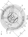
- FIG. 1A illustrates a plan view of a stator 100 including a planar composite structure (PCS) 110 having at least one dielectric layer and a plurality of conductive elements 111, 121, and 131, according to some embodiments.
- Conductive elements 111, 121 and 131 may be part of a thermal mitigation structure in accordance with an embodiment of the disclosure that can be used at the outer annulus of a PCB structure.
- PCS 110 is characterized at least in part by a center origin point 101 and a periphery 102.
- Stator 100 includes a plurality of first conductive elements 111 extending radially to a distance 142 ( r 1 ) from center origin point 101 toward periphery 102 of PCS 110 and disposed angularly on the PCS, each first conductive element terminated in a preferred termination structure 115. Further, in some embodiments stator 100 includes a plurality of second conductive elements 121 extending radially from a radius 143 ( r 2 ) from center origin point 101 toward periphery 102 and disposed angularly on the PCS. Accordingly, first conductive elements 111 are separated from one another along an angular direction, ⁇ , perpendicular to the radial direction, r, from center origin point 101 to periphery 102.
- second conductive elements 121 are separated from one another along direction, ⁇ .
- at least one of the first conductive elements 111 is connected to at least one of the second conductive elements 121 at the preferred termination structure 115, according to a connection configuration.
- Stator 100 may include multiple layers similar to the one illustrated in the planar view of FIG. 1A .
- the multiple layers may be arranged to provide a sequence of coils or windings that are connected, usually in series, to form the poles of a motor or generator.
- the poles are then typically segregated into groups, with at least one group for each phase of current supplied to the motor (or generated by the generator).
- the arrangement of conductors 111, 151, and 152 in PCS 110 creates a rotating current density and associated magnetic field. This rotating current density (and magnetic field) can exert a torque on a surrounding magnetic structure or current density.
- stator 100 may include conductive elements 111 coupled through conductive elements 151 and 152 to form the rotating current.
- Some embodiments include two sets of rare-earth magnets fixed to a shaft passing through a center origin point 101 of PCS 110, which forms a compact, high-efficiency axial field synchronous electric machine.
- stator 100 may include conductive elements 121 in a peripheral area and conductive elements 131 in an interior area. Accordingly, conductive elements 121 and 131 dissipate heat generated by stator 100, while in operation.
- stator 100 include preferred termination structures 115 and preferred starting structures 105 on either end of the radially disposed conductive elements 111.
- conductive elements 121 in the peripheral area may be coupled to conductive elements 111 through termination structures 115.
- Conductive elements 131 in the interior area may be coupled to conductive elements 111 through starting structures 105.
- Structures 105 and 115 include a connection configuration that may be a thermal connection, an electrical connection, or a combination of the two.
- a thermal connection may be one where there is a physical gap between a conductive element 111 and a conductive element 121, so that there is no electrical connectivity between the two elements.
- the proximity of the two disconnected elements 111 and 121 may be sufficient in a thermal configuration to transmit heat efficiently from one conductive element to the other (111 or 121).
- Heat is developed in stator 100 by multiple mechanisms.
- the resistance R may be approximately proportional to the feature-width (e.g., in-plane width) as seen in stator 100, since copper thickness and electrical resistivity is generally uniform. In vias, which connect one layer to the next, the copper electrical resistivity is somewhat higher than in the plane.
- the frequency of the current increases, it can be necessary to modify the resistance R to include the interaction of the current with its own magnetic field, e.g., the skin depth effect. Practically, this increases the resistance for higher-frequency components of the conducted current, but does not substantively change where the heat is generated on the stator.
- a second mechanism of heat generation is related to the interaction of copper (carrying a current or not) with a time-varying magnetic field due to the rotor magnets.
- a time-varying magnetic field due to the rotor magnets.
- ⁇ C E ⁇ ⁇ d l ⁇ ⁇ d dt ⁇ A B ⁇ ⁇ d A ⁇
- the electric field E leads to eddy-current density and associated losses anywhere there is a time-varying magnetic flux density B .
- stator 100 A design consideration in stator 100 involves a trade-off between conduction and eddy current losses in the stator active area. To reduce conduction losses, the conductors must be wider (or connected in parallel on subsequent layers). To reduce eddy current losses, the effective areas A capturing time-varying flux must be smaller, thus the conductors must be narrower.
- a third heat source involves eddy currents due to magnetic field from current carrying conductors. This effect is important to consider in the inner and outer annulus of the board, where different layers perform different functions. Also, it is important to consider this mechanism in the design of thermal mitigation structures.
- the dimensions and proportions of the different elements in stator 100 may vary as desired. In some embodiments, it may be desirable that radius 142 ( r 1 ) be equal to radius 143 ( r 2 ), resulting in no gap between one or more conductive elements 111 and 121. In other embodiments radius 142 ( r 1 ) may be smaller than radius 143 ( r 2 ), resulting in a gap between one or more conductive elements 111 and 121. Likewise, the materials forming the different elements in stator 100 may vary as desired, within the scope of the present disclosure.
- At least one of conductive elements 111, 121, 131, 151, and 152 may include copper, or carbon (e.g., a graphene layer, or a carbon nano-tube layer, or other carbon allotropes), or a copper-carbon composite, or other electrically conductive material or composite.
- Conductive elements 121, 131 may include thermally conductive material.
- conductive elements 111, 121, and 131 act as thermal conductors having reduced areas d A for eddy current loss. Additionally, conductive elements 121 may enhance the thickness consistency of stator 100 through the use of laminated copper traces in the peripheral area. Conductive elements 131 are heat removal traces on the inner area of stator 100. In some embodiments, conductive elements 131 may be electrically connected to conductive elements 121 through starting structures 105. Accordingly, starting structures 105 are similar to termination structures 115. However, starting structures 105 are typically radially distributed instead of angularly distributed due to the spatial constraints near center origin point 101.
- FIG. 1B illustrates a cross-sectional view of stator 100, according to some embodiments.
- stator 100 may include a dielectric substrate 162 sandwiched between conductive layers 161a and 161b.
- Vias 125 provide electrical conductivity between conductive layers 161a and 161b.
- vias 125 may also provide thermal conductivity between layers 161a and 161b due to the conducting material that is typically used in these elements (e.g., copper, aluminum, tin, tungsten, and derived compounds).
- Dielectric substrate 162 may include any material used in PCBs, such as a composite material including woven fiberglass with an epoxy resin binder (e.g., FR-4 and the like).
- stator 100 includes at least one of conductive elements 111, 121, or 131 (cf. FIG. 1A ) located on different conductive layers 161a and 161b.
- conductive element 111a may be one of the plurality of conductive elements 111 in the active area of stator 100 and disposed on conductive layer 161a.
- conductive element 111b may be one of the plurality of conductive elements 111 in the active area of stator 100 and disposed on conductive layer 161b.
- conductive elements 121a (cf. FIG. 6A ) and 131a correspond to conductive elements 121 and 131, disposed on conductive layer 161a.
- conductive elements 121b (cf. FIG. 6A ) and 131b correspond to conductive elements 121 and 131, disposed on conductive layer 161b.
- Conductive elements 111, 121 and 131 arranged in multiple conductive layers 161a and 161b may improve heat dissipation in stator 100.
- heat is disproportionately conveyed via the electrically conductive elements themselves.
- the thermal conductivity of copper at 401 W/(m K)
- FR-4 at 0.81 W/(mK) in-plane
- copper is even more significant as a heat conducting mechanism, having almost 1,400 times the thermal conductivity of FR-4 in the out-of-plane direction.
- the overall thermal conductivity of the stator structure depends on the relative areas of the electrically conductive elements and surrounding dielectric.
- FIG. 2 illustrates a detail of stator 100 including a plurality of conductive elements 111, 121 and 131, disposed radially on PCS 110, according to some embodiments. And conductive elements 152 disposed angularly on PCS 110.
- stator 100 further includes a plurality of third conductive elements 211 extending radially from a radius 241 ( r 3 ) from center origin point 101 toward periphery 102 and disposed angularly on PCS 110, wherein at least one of the third conductive elements 211 and at least one of the second conductive elements 121b are coincident and located on different conductive layers.
- conductive elements 211 may be included in conductive layer 161a
- conductive elements 121b may be included in conductive layer 161b.
- thermal coupling between conductive elements 111, 121 and 131 is enhanced significantly by also making an electrical connection between these conductive elements. Accordingly, some embodiments provide clearances between conductive elements 131 and conductive elements 111 in the inner area of stator 100, e.g., to provide space for conductive elements 151. Likewise, some embodiments provide clearances between conductive elements 111 and conductive elements 121 in the peripheral area of stator 100, e.g., to provide space for conductive elements 152. More generally, embodiments of stator 100 consistent with the present disclosure provide electrical clearances between two conducting elements that are at different electric potentials, while still providing good thermal coupling through a small gap of dielectric material separating the two.
- this approach is particularly effective (e.g., vias 125 and conductive layers 162a and 162b, cf. FIG. 1B ). Even if a conductive element is interrupted on a first conductive layer, a via section across conductive layers provides heat removal from the first conductive layer to a second conductive layer.
- the electrical and thermal coupling between conductive elements 111 and conductive elements 131 includes a starting point of one of conductive elements 111 at a distance 141 ( r 0 ) from center origin point 101 contacting starting structure 105. And a starting point of one of conductive elements 131 at a distance 242 ( r -1 ) from center origin point 101.
- the opposite end of conductive element 111 ends on termination structure 115 at a distance 142 ( r 1 ) from center origin point 101.
- FIG. 3 illustrates a detail of an inner area proximal to a center origin point 101 of stator 100, including a plurality of conducting elements 111 and 131 disposed radially and conductive elements 151 disposed angularly on PCS 110, according to some embodiments. Due to the spatial constraints near center origin point 101, in some embodiments only certain conductive elements 131 may be thermally and/or electrically coupled to corresponding conductive elements 111 through a starting structure 105. This arrangement avoids making undesirable electrical contact between adjacent conductive elements 131 near center origin point 101.
- FIG. 4 illustrates a detail of an inner area proximal to center origin point 101 of stator 100, including a plurality of conducting elements 111 disposed radially, according to some embodiments.
- a conductive element 151 is disposed angularly.
- conductive elements 431a and 431b are disposed on different conductive layers on the PCS.
- conductive elements 431a alternate with conductive elements 431b on different layers of multilayer PCS 110.
- Inner vias in starting structures 105 dissipate heat through conductive elements 111.
- FIG. 5 illustrates a detail of a conductive element 111 including a termination structure 115, according to some embodiments.
- Termination structure 115 has a T-shaped or "hammerhead" configuration.
- termination structure 115 may include a square pad instead of a hammerhead configuration.
- Termination structure 115 improves the angular distribution (i.e., along the ⁇ direction) of heat from different sources in the transition between the active and the peripheral areas of stator 100, such as eddy currents and conductive losses from conducting elements 111 ending at termination structure 115.
- termination structure 115 reduces the area wherein losses can occur due to incident time-varying magnetic fields (cf. Eq. 1).
- Some embodiments include one or more vias between layers near the outer portions of termination structure 115, which in conjunction with the spatial extent of the hammerhead feature tends to reduce the angular concentration of heat compared to a single-point thermal termination (e.g., starting structure 105, cf. FIG. 1A ).
- the hammerhead feature of termination structure 115 reduces the exposure of solid-copper elements in the peripheral area to time varying magnetic field leakage from the permanent magnet assembly over the active area.
- the specific dimensions and ratios shown in FIG. 2 may be subject to optimization depending on factors including a desired motor or generator design.
- the disproportionate ratio of thermal conductivity between the two basic materials in stator 100 e.g., copper for conductive elements 111, 121, and 131, vs. FR-4 in dielectric substrate 162 suggests that different designs of termination structure 115 that are substantially consistent with stator 100 and termination structure 115, may be equally effective for heat dissipation.
- FIGS. 6A-I illustrate details of different connection configurations 615a, 615b, 615c, and 615d (collectively referred hereinafter as connection configurations 615), according to some embodiments.
- Connection configurations 615 include first conductive elements 111a,b connected to second conductive elements 121a,b at termination structure 115.
- Termination structure 115 includes vias 125 forming a thermal and electrical coupling between conductive elements 111a,b and conductive elements 121a,b.
- Three-dimensional axis (Z, r, ⁇ ) is consistent with those shown in FIGS. 1A-B , and FIG. 2-4 . Axis labeling and specific orientation of the elements in the figures are chosen for illustrative purposes only and should not be deemed limiting the different embodiments depicted.
- FIG. 6A shows a perspective view of connection configuration 615a, according to some embodiments.
- Connection configuration 615a includes conductive elements 111a,b and 121a,b in two different conductive layers (e.g., conductive layer 161a and 161b, cf. FIG. 1B ), forming an electrical and thermal coupling at termination structure 115. More specifically, connection configuration 615a provides electrical and thermal coupling between conductive elements 111a,b and conductive elements 121a,b.
- FIG. 6B is a cross-section view of connection configuration 615a, along the length of conductive elements 111a,b and 121a,b illustrated in FIG. 6A.
- FIG. 6B also shows schematically the heat flow in connection configuration 615a from conductive elements 111a,b to conductive elements 121a,b and ultimately to heat sink 620.
- conductive elements 121a and 121b be at least partially coincident but located in opposite conductive layers of PCS 110. Accordingly, the heat flow from conductive elements 111a,b to conductive elements 121a,b is enhanced along the radial path of conductive elements 111a,b, and 121a,b.
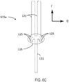
- FIG. 6C shows a plan view of connection configuration 615a including conductive elements 111a,b and 121a,b in the same conductive layer, forming an electrical and thermal coupling at termination structure 115.
- Termination structure 115 includes a hammerhead feature having four (4) vias 125 to provide enhanced heat dissipation and electrical connection between layers.
- FIG. 6D shows a perspective view of connection configuration 615b including conductive elements 111a,b, 121a,b, and 152a in two different conductive layers, forming an electrical and thermal coupling at termination structure 115. More specifically, connection configuration 615b provides electrical and thermal coupling between conductive elements 111a,b and conductive element 121b through vias 125 in termination structure 115. Further, connection configuration 615b provides thermal coupling between conductive element 111a and conductive element 121a on the same conductive layer, and with no electrical connection between them. Embodiments including connection configuration 615b may be desirable when conductive element 152a operates at a different electrical potential as either one of conductive elements 111a or 121a. Some embodiments including connection configuration 615b may be desirable when conductive element 121a operates at a different electrical potential as conductive element 111a.
- FIG. 6E is a cross-section view of connection configuration 615b along the length of conductive elements 111a,b and 121 a,b illustrated in FIG. 6D.
- FIG. 6E also shows schematically the heat flow from conductive elements 111a,b to conductive elements 121a,b into heat sink 620. Because conductive elements 121a and 121b are at least partially coincident along the plane of PCS 110, heat flows from conductive element 121b to conductive element 121a irrespective of any difference in electrical potential between the two conductive elements.
- FIG. 6F shows a perspective view of connection configuration 615c including conductive elements 111a,b, 121a,b and 152a in two different conductive layers, and forming an electrical and thermal coupling at termination structure 115.
- Connection configuration 615c is similar to connection configuration 615b in that conductive elements 111a and 121a are not electrically connected, while conductive elements 111a,b is electrically and thermally connected to conductive element 121b through vias 125 in termination feature 115.
- termination structure 115 has a hammerhead configuration (cf. FIG. 5 ). Accordingly, the heat flow from conductive elements 111a,b to conductive elements 121a,b in connection configuration 615c is enhanced along the radial path of conductive elements 111a,b, and 121a,b, regardless of the electrical configuration.
- FIG. 6G is a cross-section view of connection configuration 615c along the length of conductive elements 111a,b (collectively, 111) and 121a,b (collectively 121) illustrated in FIG. 6F.
- FIG. 6G also shows schematically the heat flow from conductive elements 111a,b to conductive elements 121a,b into heat sink 620.
- FIG. 6H shows a perspective view of connection configuration 615d including conductive elements 111, 121 and 152b in two different conductive layers, forming an electrical and thermal coupling at termination structure 115.
- Connection configuration 615d is similar to connection configurations 615b and 615c in that conductive elements in different conductive layers are electrically and thermally connected (i.e., conductive element 111b and conductive element 121a, through vias 125). However, in connection configuration 615d conductive element 152b is disposed on another conductive layer of PCS 110. Accordingly, it may be desirable to electrically isolate conductive element 111b from conductive elements 121b.
- FIG. 6I is a cross-section view of connection configuration 615d along the length of conductive elements 111 and 121 illustrated in FIG. 6H.
- FIG. 6I also shows schematically the heat flow from conductive elements 111a,b to conductive elements 121a,b into heat sink 620. As shown, the heat flow from conductive elements 111a,b to conductive elements 121a,b in connection configuration 615d is enhanced along the radial path of conductive elements 111a,b, and 121a,b, regardless of the electrical configuration.
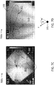
- FIGS. 7A-D illustrate thermal images of stators 700a and 700b (collectively referred hereinafter to as 'stators 700'), respectively, including PCS 110 having at least one dielectric substrate 162 and conductive layers 161a and 161b while dissipating heat, according to some embodiments.
- Stator 700a does not include conductive elements 111 and 121, while stator 700b does (cf. FIGS. 1A-B ).
- Thermal images are obtained by introducing heat via conduction loss in selected locations on stators 700 to emulate the temperature distribution in an operating motor or generator. Heat sources and sinks in an operating motor or generator include the surrounding magnetic and mechanical components. This approach allows imaging and comparison of thermal performance between different stator designs consistent with embodiments disclosed herein.
- Introducing heat via conduction includes configuring a power supply to deliver a fixed amount of power (approximately 20W) to stators 700 for 10 minutes.
- Stators 700 were then imaged with a FLIR digital IR camera. Boundary conditions were established by placing stators 700 in an enclosure 750, leaving an exposed half of the stator available for thermal imaging. Additionally, only three of the four corners of PCS 110 were clamped firmly to enclosure 750. This clamping configuration allows a comparison of the efficacy of the thermal designs in removing heat from stators 700 to enclosure 750 with all other conditions held constant. Stators 700 were excited across two of the three wye-connected phases.
- FIG. 7A shows that stator 700a is hotter at the left-hand corner where there is no good thermal contact, the temperature is fairly uniform across stator 700a even where it is well terminated. This suggests that independent of the quality of the heat sinking case, it is difficult to convey heat out of stator 700a.
- FIGS. 7B-D show the result of the same test and measurement procedure for stator 700b, including conductive elements 111 and 121 as disclosed herein (cf. FIGS. 1A-B , 2-5 , and 6A-I ). Temperature readings in FIGS. 7A-7D are illustrative only and by no means limiting of embodiments disclosed herein. However, it is revealing that the parts of stator 700b which are clamped to enclosure 750 (darker portions in FIGS. 7B-D ) are relatively cooler than the parts with poor thermal termination (brighter portions in FIGS. 7B-D ). This suggests that features consistent with embodiments of the present invention are effective in removing heat from stator 700b to enclosure 750.
- stator 700b shows a distinct pattern between the areas with good thermal termination and the corner with poor thermal termination. However, in this case, the thermal signature of the phases 710c immediately adjacent to the clamp is almost entirely absent.
- FIG. 7D shows the effect in FIG. 7C in further detail. Note the difference between the left-portion of the board (well clamped) and the right side (worse contact) and the absence of a sharp gradient in the radial direction (r, towards the sink), relative to the angular direction ( ⁇ , as the boundary condition changes). Overall, a comparison the heat-removal efficacy of stator 700a with stator 700b shows that incorporating the features described in one or more of the embodiments of this invention (e.g., conductive elements 111, 121, and 131) can remove heat from the active region (which includes conductive elements 111) with significantly greater efficacy.
- conductive elements 111, 121, and 131 can remove heat from the active region (which includes conductive elements 111) with significantly greater efficacy.
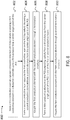
- FIG. 8 illustrates a flow chart in a method 800 for manufacturing a stator including a planar composite layer (PCS) having at least one dielectric layer and a plurality of conductive layers, according to some embodiments (e.g., stator 100, PCS 110, dielectric substrate 162, conductive layers 161a, b, cf. FIGS. 1A-B through FIG. 6 ).
- PCS planar composite layer
- Methods consistent with the present disclosure may include at least some, but not all of the steps illustrated in method 800, performed in a different sequence. Furthermore, methods consistent with the present disclosure may include at least two or more steps as in method 800 performed overlapping in time, or almost simultaneously.
- Step 802 includes forming a first conductive layer on the PCS by radially disposing a first conductive element on a dielectric substrate up to a first distance from a center origin point of the PCS (e.g., conductive layer 161a, dielectric substrate 162, and conductive elements 111, 111a,b , cf. FIGS. 1A-B , and FIGS. 4 and 6A-I ).
- a center origin point of the PCS e.g., conductive layer 161a, dielectric substrate 162, and conductive elements 111, 111a,b , cf. FIGS. 1A-B , and FIGS. 4 and 6A-I ).
- Step 804 includes forming a second conductive layer opposite the first conductive layer on the PCS by radially disposing a second conductive element extending radially from a second distance from the center origin point of the PCS (e.g., conductive layer 161b, and conductive elements 121, 121a,b , 131, 131a,b, 211, cf. FIGS. 1A-B , FIG. 2 and FIGS.4 and 6A-I ).
- Step 806 includes coupling the first conductive element with the second conductive element through a termination structure (e.g., termination structure 115, cf. FIG. 1A ).
- a termination structure e.g., termination structure 115, cf. FIG. 1A
- Step 808 includes forming a third conductive element on the PCS extending radially from a third distance from the center origin point of the PCS in one of the first or second conductive layers (e.g., conductive elements 121, 121a,b , 131, 131a,b, 211, cf. FIGS. 1A-B , FIG. 2 and FIGS.4 and 6A-I ).
- Step 810 includes coupling the first conductive element with the third conductive element through a second termination structure (e.g., termination structures 105 or 115, cf. FIG. 1A ).
- coupling the first conductive element with the second or third conductive elements may include any one of a thermal coupling, an electrical coupling, or both.
- the coupling may include a connection configuration having starting and/or termination structures including vias that go through the dielectric substrate from one conductive layer to another conductive layer (e.g., vias 125 and connection configurations 615, cf. FIGS. 6A-I ).
- the first conductive element is in an active area of the PCS and at least one of the second or third conductive elements is in an inner area of the PCS.
- the termination structure may be radially oriented on the PCS due to spatial constraints (e.g., termination structure 105).
- the termination structure may be angularly oriented on the PCS (e.g., termination structure 115).
Landscapes
- Engineering & Computer Science (AREA)
- Power Engineering (AREA)
- Microelectronics & Electronic Packaging (AREA)
- Windings For Motors And Generators (AREA)
- Insulation, Fastening Of Motor, Generator Windings (AREA)
- Production Of Multi-Layered Print Wiring Board (AREA)
- Motor Or Generator Cooling System (AREA)
- Structure Of Printed Boards (AREA)
- Brushless Motors (AREA)
- Indicating Measured Values (AREA)
- Devices For Indicating Variable Information By Combining Individual Elements (AREA)
- Instrument Panels (AREA)
- Parts Printed On Printed Circuit Boards (AREA)
Priority Applications (2)
| Application Number | Priority Date | Filing Date | Title |
|---|---|---|---|
| EP19184929.8A EP3570412A1 (en) | 2015-10-02 | 2016-09-30 | Structures and methods for thermal management in printed circuit board stators |
| PL16784315T PL3357147T3 (pl) | 2015-10-02 | 2016-09-30 | Struktury i sposoby zarządzania temperaturą w stojanach obwodów drukowanych |
Applications Claiming Priority (4)
| Application Number | Priority Date | Filing Date | Title |
|---|---|---|---|
| US201562236422P | 2015-10-02 | 2015-10-02 | |
| US201562236407P | 2015-10-02 | 2015-10-02 | |
| US15/199,527 US9673684B2 (en) | 2015-10-02 | 2016-06-30 | Structures and methods for thermal management in printed circuit board stators |
| PCT/US2016/054704 WO2017059213A1 (en) | 2015-10-02 | 2016-09-30 | Structures and methods for thermal management in printed circuit board stators |
Related Child Applications (2)
| Application Number | Title | Priority Date | Filing Date |
|---|---|---|---|
| EP19184929.8A Division EP3570412A1 (en) | 2015-10-02 | 2016-09-30 | Structures and methods for thermal management in printed circuit board stators |
| EP19184929.8A Division-Into EP3570412A1 (en) | 2015-10-02 | 2016-09-30 | Structures and methods for thermal management in printed circuit board stators |
Publications (2)
| Publication Number | Publication Date |
|---|---|
| EP3357147A1 EP3357147A1 (en) | 2018-08-08 |
| EP3357147B1 true EP3357147B1 (en) | 2020-03-25 |
Family
ID=57113815
Family Applications (3)
| Application Number | Title | Priority Date | Filing Date |
|---|---|---|---|
| EP16784315.0A Active EP3357147B1 (en) | 2015-10-02 | 2016-09-30 | Structures and methods for thermal management in printed circuit board stators |
| EP16778659.9A Active EP3357144B1 (en) | 2015-10-02 | 2016-09-30 | Printed circuit board stator |
| EP19184929.8A Withdrawn EP3570412A1 (en) | 2015-10-02 | 2016-09-30 | Structures and methods for thermal management in printed circuit board stators |
Family Applications After (2)
| Application Number | Title | Priority Date | Filing Date |
|---|---|---|---|
| EP16778659.9A Active EP3357144B1 (en) | 2015-10-02 | 2016-09-30 | Printed circuit board stator |
| EP19184929.8A Withdrawn EP3570412A1 (en) | 2015-10-02 | 2016-09-30 | Structures and methods for thermal management in printed circuit board stators |
Country Status (18)
| Country | Link |
|---|---|
| US (1) | US9673684B2 (https=) |
| EP (3) | EP3357147B1 (https=) |
| JP (2) | JP6892855B2 (https=) |
| KR (2) | KR102412683B1 (https=) |
| CN (2) | CN108141111B (https=) |
| AU (2) | AU2016329080B2 (https=) |
| BR (2) | BR112018006113B1 (https=) |
| CA (2) | CA2999999C (https=) |
| DK (2) | DK3357144T3 (https=) |
| ES (2) | ES2857909T3 (https=) |
| MX (3) | MX384150B (https=) |
| MY (1) | MY189408A (https=) |
| PH (2) | PH12018500722A1 (https=) |
| PL (2) | PL3357147T3 (https=) |
| RU (2) | RU2719305C1 (https=) |
| TW (2) | TWI705658B (https=) |
| WO (2) | WO2017059213A1 (https=) |
| ZA (2) | ZA201801922B (https=) |
Families Citing this family (30)
| Publication number | Priority date | Publication date | Assignee | Title |
|---|---|---|---|---|
| US9859763B2 (en) * | 2015-10-02 | 2018-01-02 | E-Circuit Motors, Inc. | Structures and methods for controlling losses in printed circuit boards |
| US11121614B2 (en) | 2017-06-05 | 2021-09-14 | E-Circuit Motors, Inc. | Pre-warped rotors for control of magnet-stator gap in axial flux machines |
| US9800109B2 (en) * | 2015-10-02 | 2017-10-24 | E-Circuit Motors, Inc. | Structures and methods for controlling losses in printed circuit boards |
| US11527933B2 (en) | 2015-10-02 | 2022-12-13 | E-Circuit Motors, Inc. | Stator and rotor design for periodic torque requirements |
| US10170953B2 (en) | 2015-10-02 | 2019-01-01 | E-Circuit Motors, Inc. | Planar composite structures and assemblies for axial flux motors and generators |
| US11342813B2 (en) * | 2016-04-30 | 2022-05-24 | Blue Canyon Technologies Inc. | Printed circuit board axial flux motor with thermal element |
| US11177726B2 (en) | 2017-01-11 | 2021-11-16 | Infinitum Electric, Inc. | System and apparatus for axial field rotary energy device |
| US10141804B2 (en) | 2017-01-11 | 2018-11-27 | Infinitum Electric Inc. | System, method and apparatus for modular axial field rotary energy device |
| US10186922B2 (en) | 2017-01-11 | 2019-01-22 | Infinitum Electric Inc. | System and apparatus for axial field rotary energy device |
| US11831211B2 (en) | 2017-06-05 | 2023-11-28 | E-Circuit Motors, Inc. | Stator and rotor design for periodic torque requirements |
| US11005322B2 (en) | 2017-06-05 | 2021-05-11 | E-Circuit Motors, Inc. | Rotor assemblies for axial flux machines |
| TWI786130B (zh) * | 2017-07-10 | 2022-12-11 | 美商E電路馬達股份有限公司 | 用於軸向磁通電動機及發電機之改良平面複合結構 |
| WO2019190959A1 (en) | 2018-03-26 | 2019-10-03 | Infinitum Electric Inc. | System and apparatus for axial field rotary energy device |
| US11366525B2 (en) | 2018-07-03 | 2022-06-21 | Boyd Randolph Hobbs | Handwheels and associated control consoles |
| KR20240122577A (ko) | 2018-07-10 | 2024-08-12 | 인피니텀 일렉트로닉, 아이앤씨. | 축방향 필드 회전 에너지 장치용 시스템 및 장치 |
| JP7617566B2 (ja) | 2018-11-01 | 2025-01-20 | イー-サーキット モーターズ, インコーポレイテッド | 周期的トルク要件のためのステータおよびロータ設計 |
| US20200212741A1 (en) | 2018-12-26 | 2020-07-02 | Blue Canyon Technologies Inc. | Axial flux motor |
| US11283319B2 (en) * | 2019-11-11 | 2022-03-22 | Infinitum Electric, Inc. | Axial field rotary energy device with PCB stator having interleaved PCBS |
| EP4059120A1 (en) | 2019-11-12 | 2022-09-21 | E-Circuit Motors, Inc. | Improved rotor assemblies for axial flux machines |
| US20210218304A1 (en) | 2020-01-14 | 2021-07-15 | Infinitum Electric, Inc. | Axial field rotary energy device having pcb stator and variable frequency drive |
| CN111182706A (zh) * | 2020-02-28 | 2020-05-19 | 广东省水源美农业科技有限公司 | 低温等离子反应器 |
| CN111416488B (zh) * | 2020-04-01 | 2021-01-05 | 江苏苏杭电子有限公司 | 特种电机用紫铜线圈的加工方法 |
| EP3961880A1 (de) * | 2020-08-31 | 2022-03-02 | Siemens Aktiengesellschaft | Aktivteil einer elektrischen maschine mit gedrucktem leiter |
| JP7784674B2 (ja) | 2021-02-17 | 2025-12-12 | イー-サーキット モーターズ, インコーポレイテッド | 軸方向磁束機械のための平面固定子構成 |
| US11482908B1 (en) | 2021-04-12 | 2022-10-25 | Infinitum Electric, Inc. | System, method and apparatus for direct liquid-cooled axial flux electric machine with PCB stator |
| MX2024001426A (es) | 2021-07-30 | 2024-05-14 | E Circuit Motors Inc | Placas de circuito impreso rellenas de material magnetico y estatores de placas de circuito impreso. |
| US11336130B1 (en) * | 2021-08-17 | 2022-05-17 | E-Circuit Motors, Inc. | Low-loss planar winding configurations for an axial flux machine |
| US12259643B2 (en) | 2022-07-20 | 2025-03-25 | Nodal Film Systems Llc | Camera head with integrated PCB stator motors |
| US12278089B2 (en) | 2023-01-31 | 2025-04-15 | Applied Materials, Inc. | Plasma uniformity control system and methods |
| US12418256B2 (en) | 2023-10-20 | 2025-09-16 | Nodal Film Systems Llc | Control systems and methods with haptic feedback |
Family Cites Families (89)
| Publication number | Priority date | Publication date | Assignee | Title |
|---|---|---|---|---|
| US2970238A (en) | 1959-02-12 | 1961-01-31 | Printed Motors Inc | Printed circuit armature |
| CH376570A (fr) * | 1959-11-13 | 1964-04-15 | S E A Societe D Electronique E | Machine électrique tournante à entrefer axial |
| US3096455A (en) | 1962-03-08 | 1963-07-02 | Basic Motor Developments Inc | Printed disc electrical machinery |
| NL7802552A (en) * | 1967-04-03 | 1978-06-30 | Kollmorgen Corp | Aluminium armature method |
| DE2409681A1 (de) * | 1974-02-28 | 1975-09-11 | Retobobina Handelsanstalt | Elektrische ankerwicklung |
| US4115915A (en) | 1975-07-31 | 1978-09-26 | General Electric Company | Process for manufacturing motor having windings constructed for automated assembly |
| JPS5836145A (ja) | 1981-08-28 | 1983-03-03 | Kangiyou Denki Kiki Kk | 積層配線体 |
| JPS59213287A (ja) | 1983-05-18 | 1984-12-03 | Kokusai Dengiyou Kk | 直流電磁石による回転体付き吸着装置 |
| DE3526166C2 (de) * | 1984-07-23 | 1996-05-02 | Asahi Chemical Ind | Bürstenloser Elektromotor und Verfahren zum Herstellen einer Spuleneinheit für diesen |
| CH660542A5 (fr) | 1984-08-31 | 1987-04-30 | Asgalium Sa | Moteur electrique. |
| JPH0669005B2 (ja) * | 1986-02-13 | 1994-08-31 | ソニー株式会社 | 多層シ−トコイル |
| US4733115A (en) | 1986-12-16 | 1988-03-22 | Eastman Kodak Company | Electric motor |
| US5099162A (en) | 1987-07-22 | 1992-03-24 | Canon Kabushiki Kaisha | Coil of superconducting material for electric appliance and motor utilizing said coil |
| US5332460A (en) | 1988-08-09 | 1994-07-26 | Nippon Seiko Kabushiki Kaisha | Method of manufacturing a seal ring for magnetic fluid seal device |
| KR910010797A (ko) | 1989-11-29 | 1991-06-29 | 서주인 | 주파수발전기의 코일패턴 |
| DE4125044A1 (de) * | 1991-07-29 | 1993-02-04 | Wolfgang Hill | Als scheibenlaeufer ausgebildeter elektromotor mit radial zur rotationsachse angeordnetem rotor und blechpaket |
| EP0563852A1 (en) | 1992-04-02 | 1993-10-06 | Siemens Aktiengesellschaft | Zag fuse for reduced blow-current applications |
| KR940011416B1 (ko) * | 1992-11-24 | 1994-12-15 | 포항종합제철주식회사 | 전로출강시 출강류의 제어방법 |
| WO1995034935A1 (en) | 1994-06-15 | 1995-12-21 | Philips Electronics N.V. | Flat electric motor |
| US5710476A (en) | 1995-01-31 | 1998-01-20 | Interscience, Inc. | Armature design for an axial-gap rotary electric machine |
| DE19503511C5 (de) | 1995-02-03 | 2010-11-04 | Siemens Ag | Synchron-Linearmotor |
| JP3508957B2 (ja) * | 1995-05-17 | 2004-03-22 | 株式会社安川電機 | シートコイル形レゾルバ |
| JPH10322156A (ja) * | 1996-06-10 | 1998-12-04 | Fuji Electric Co Ltd | 電力変換器用ノイズフィルタ |
| US6411002B1 (en) * | 1996-12-11 | 2002-06-25 | Smith Technology Development | Axial field electric machine |
| US5982069A (en) * | 1998-06-30 | 1999-11-09 | Rao; Dantam K. | Axial gap machine phase coil having tapered conductors with increasing width in radial direction |
| US6628038B1 (en) | 1999-01-14 | 2003-09-30 | Kabushiki Kaisha Yaskawa Kenki | Resolver using sheet coil |
| CN1520632A (zh) | 2001-06-26 | 2004-08-11 | �Ƚ�ת��ϵͳ���Ϲ�˾ | 无刷直流电动机 |
| PT1590871E (pt) * | 2003-02-07 | 2008-08-27 | Core Motion Inc | Dispositivo energético rotativo de campo axial de condutor optimizado |
| JP2004270544A (ja) | 2003-03-07 | 2004-09-30 | Matsushita Electric Ind Co Ltd | 着磁治具および電動圧縮機ならびに回転子の組み立て方法および電動圧縮機の組み立て方法 |
| US7582999B2 (en) * | 2003-11-20 | 2009-09-01 | Intelligent Electric Motor Solutions Pty Ltd | Electric machine having a magnetically inducible core |
| DE102004021661A1 (de) * | 2004-05-03 | 2005-12-15 | BSH Bosch und Siemens Hausgeräte GmbH | Kommutatormotor mit mehreren Feldwicklungsgruppen |
| CH697889B1 (fr) | 2004-05-07 | 2009-03-13 | Etel Sa | Procédé et dispositif de positionnement et de fixation d'aimants sur une culasse magnétique d'un moteur. |
| US20060055265A1 (en) | 2004-09-16 | 2006-03-16 | Zalusky James T | Printed circuit board motor |
| US8058762B2 (en) | 2005-01-19 | 2011-11-15 | Daikin Industries, Ltd. | Rotor, axial gap type motor, method of driving motor, and compressor |
| DE102005011158A1 (de) | 2005-03-09 | 2006-09-14 | Joachim Fiedler | Magnethaltevorrichtung |
| JP2007059507A (ja) | 2005-08-23 | 2007-03-08 | Keihin Corp | 基板搭載用トランス |
| EP1826889B1 (de) | 2006-02-24 | 2015-09-30 | ThyssenKrupp Aufzugswerke GmbH | Verfahren und Vorrichtung zum Anbringen von Magneten |
| US7750522B2 (en) | 2006-07-18 | 2010-07-06 | Danotek Motion Technologies | Slow-speed direct-drive generator |
| US9129741B2 (en) | 2006-09-14 | 2015-09-08 | Qualcomm Incorporated | Method and apparatus for wireless power transmission |
| JP2008099429A (ja) | 2006-10-11 | 2008-04-24 | Asmo Co Ltd | プリントコイル及びプリントモータ |
| US20080100166A1 (en) | 2006-10-26 | 2008-05-01 | Deere & Company | Motor having stator with generally planar windings |
| US8558425B2 (en) | 2006-10-26 | 2013-10-15 | Deere & Company | Motor having stator with generally planar windings |
| US8598761B2 (en) | 2007-05-03 | 2013-12-03 | In Motion Technologies Pty., Ltd. | Rotor magnet positioning device |
| TW200913438A (en) | 2007-09-13 | 2009-03-16 | Metal Ind Res & Dev Ct | Slot-less windings applied to rotating electronic devices and the manufacturing method thereof |
| WO2009068079A1 (de) | 2007-11-27 | 2009-06-04 | Ina Drives & Mechatronics Gmbh & Co. Ohg | Elektronisch kommutierter scheibenläufermotor mit einer vielzahl von leiterschichten umfassenden verbundplatinen |
| FR2927736B1 (fr) * | 2008-02-20 | 2014-12-05 | Leroy Somer Moteurs | Stator de machine electrique tournante. |
| US7800471B2 (en) | 2008-04-04 | 2010-09-21 | Cedar Ridge Research, Llc | Field emission system and method |
| US8368495B2 (en) | 2008-04-04 | 2013-02-05 | Correlated Magnetics Research LLC | System and method for defining magnetic structures |
| US20100000112A1 (en) | 2008-07-02 | 2010-01-07 | Whirlpool Corporation | Dispensing dryer dosing sensing |
| US9257876B2 (en) | 2008-11-14 | 2016-02-09 | Metal Industries Research & Development Centre | Motor integrated to electronic device |
| TWI425742B (zh) | 2008-11-14 | 2014-02-01 | Metal Ind Res & Dev Ct | Integrated in the electronic device of the motor |
| CN102292897B (zh) * | 2009-01-16 | 2014-04-02 | 科尔风力发电公司 | 用于轴向场装置的扇块式定子 |
| KR20120006029A (ko) | 2009-03-30 | 2012-01-17 | 티안진 타슬리 파마슈티컬 컴퍼니 리미티드 | 신규한 화합물 살비아놀릭산 l, 이의 제조방법 및 용도 |
| US8450404B2 (en) | 2009-06-16 | 2013-05-28 | Honeywell Federal Manufacturing & Technologies, Llc | Compositions containing borane or carborane cage compounds and related applications |
| US9279852B2 (en) | 2009-11-30 | 2016-03-08 | Essai, Inc. | Systems and methods for conforming test tooling to integrated circuit device profiles with sockets having secured and replaceable bushings |
| JP4699570B1 (ja) * | 2009-12-22 | 2011-06-15 | 株式会社コスモメカニクス | ディスク型コイル |
| US8225497B2 (en) | 2010-01-05 | 2012-07-24 | General Electric Company | Permanent magnet rotor installation systems |
| US9154024B2 (en) | 2010-06-02 | 2015-10-06 | Boulder Wind Power, Inc. | Systems and methods for improved direct drive generators |
| JP5545110B2 (ja) | 2010-08-06 | 2014-07-09 | ブラザー工業株式会社 | 印刷のための制御装置及びコンピュータプログラム |
| GB2485185A (en) | 2010-11-04 | 2012-05-09 | Pipera Technologies Ltd | Axial gap electrical machine having integrated stator |
| JP5644551B2 (ja) * | 2011-01-31 | 2014-12-24 | 日立工機株式会社 | ディスクモータ及び電動作業機 |
| CN106300851B (zh) | 2011-04-12 | 2019-12-17 | 巨石风力股份有限公司 | 气隙控制系统和方法 |
| EP2697895B1 (en) | 2011-04-13 | 2019-09-04 | Boulder Wind Power, Inc. | Flux focusing arrangement for permanent magnets, methods of fabricating such arrangements, and machines including such arrangements |
| EP2747705B1 (en) | 2011-08-22 | 2017-06-28 | Cook Medical Technologies LLC | Emergency vessel repair prosthesis deployment system |
| US20130052491A1 (en) | 2011-08-26 | 2013-02-28 | Roger Neil Bull | Thermal management system for a multi-cell array |
| TWI440281B (zh) | 2011-08-31 | 2014-06-01 | 建準電機工業股份有限公司 | 馬達定子 |
| JP5880817B2 (ja) * | 2011-09-28 | 2016-03-09 | 日立工機株式会社 | ディスクモータ及びそれを備えた電動作業機 |
| DE102011086214A1 (de) | 2011-11-11 | 2013-05-16 | Magnet-Physik Dr. Steingroever Gmbh | Verfahren und Vorrichtung zum Halten von Magnetkörpern während ihrer Magnetisierung und zum Einbringen der magnetisierten Magnetkörpern in ein Bauteil eines magnetischen Systems |
| WO2013122543A1 (en) | 2012-02-13 | 2013-08-22 | Agency For Science, Technology And Research | Motor and method for assembling the same |
| KR101882700B1 (ko) | 2012-07-18 | 2018-07-30 | 삼성디스플레이 주식회사 | 칩온글래스 기판 및 칩온글래스 기판에서의 접속 저항 측정 방법 |
| TWI487883B (zh) | 2012-07-19 | 2015-06-11 | 財團法人工業技術研究院 | 感測器的讀取裝置與驅動方法 |
| US8339019B1 (en) | 2012-07-30 | 2012-12-25 | Boulder Wind Power, Inc. | Structure for an electromagnetic machine having compression and tension members |
| US8716913B2 (en) | 2012-08-07 | 2014-05-06 | Boulder Wind Power, Inc. | Devices and methods for magnetic pole and back iron retention in electromagnetic machines |
| CN103001426A (zh) | 2012-11-19 | 2013-03-27 | 腾达电动科技镇江有限公司 | 印刷电路板无铁芯盘式电机 |
| US20140152136A1 (en) | 2012-12-03 | 2014-06-05 | Boulder Wind Power, Inc. | Devices and methods for magnetic pole retention in electromagnetic machines |
| US20140201291A1 (en) | 2013-01-16 | 2014-07-17 | Long Russell | System and Method for Creating a Geographically-Defined Social Network |
| US8723052B1 (en) | 2013-02-27 | 2014-05-13 | Boulder Wind Power, Inc. | Methods and apparatus for optimizing electrical interconnects on laminated composite assemblies |
| US8785784B1 (en) | 2013-03-13 | 2014-07-22 | Boulder Wind Power, Inc. | Methods and apparatus for optimizing structural layout of multi-circuit laminated composite assembly |
| US20140262499A1 (en) | 2013-03-14 | 2014-09-18 | Boulder Wind Power, Inc. | Methods and apparatus for optimizing electrically inoperative zones on laminated composite assemblies |
| US8941961B2 (en) | 2013-03-14 | 2015-01-27 | Boulder Wind Power, Inc. | Methods and apparatus for protection in a multi-phase machine |
| US8736133B1 (en) | 2013-03-14 | 2014-05-27 | Boulder Wind Power, Inc. | Methods and apparatus for overlapping windings |
| CN104426263B (zh) | 2013-08-26 | 2017-12-19 | 苏州奥宝杰电机科技有限公司 | 转子及采用该转子的无刷电机 |
| US20150084446A1 (en) | 2013-09-24 | 2015-03-26 | Electro-Motor Dynamics, LLC | Direct drive stacked motor acuator |
| JP2015115973A (ja) * | 2013-12-09 | 2015-06-22 | 株式会社安川電機 | 回転電機の回転子及び回転電機 |
| US9793775B2 (en) | 2013-12-31 | 2017-10-17 | Boulder Wind Power, Inc. | Methods and apparatus for reducing machine winding circulating current losses |
| US20150188391A1 (en) | 2013-12-31 | 2015-07-02 | Boulder Wind Power, Inc. | Apparatus for cooling an electromagnetic machine |
| WO2015134855A1 (en) | 2014-03-07 | 2015-09-11 | Boulder Wind Power, Inc. | Methods and apparatus for integrated machine segmentation |
| US9899886B2 (en) | 2014-04-29 | 2018-02-20 | Boulder Wind Power, Inc. | Devices and methods for magnetic flux return optimization in electromagnetic machines |
| US10177620B2 (en) | 2014-05-05 | 2019-01-08 | Boulder Wind Power, Inc. | Methods and apparatus for segmenting a machine |
-
2016
- 2016-06-30 US US15/199,527 patent/US9673684B2/en active Active
- 2016-09-30 AU AU2016329080A patent/AU2016329080B2/en active Active
- 2016-09-30 EP EP16784315.0A patent/EP3357147B1/en active Active
- 2016-09-30 CA CA2999999A patent/CA2999999C/en active Active
- 2016-09-30 EP EP16778659.9A patent/EP3357144B1/en active Active
- 2016-09-30 CN CN201680057559.5A patent/CN108141111B/zh active Active
- 2016-09-30 PL PL16784315T patent/PL3357147T3/pl unknown
- 2016-09-30 AU AU2016331798A patent/AU2016331798B2/en active Active
- 2016-09-30 KR KR1020187012460A patent/KR102412683B1/ko active Active
- 2016-09-30 CN CN201680057552.3A patent/CN108141089B/zh active Active
- 2016-09-30 MY MYPI2018701291A patent/MY189408A/en unknown
- 2016-09-30 ES ES16778659T patent/ES2857909T3/es active Active
- 2016-09-30 ES ES16784315T patent/ES2792028T3/es active Active
- 2016-09-30 CA CA3000002A patent/CA3000002C/en active Active
- 2016-09-30 BR BR112018006113-1A patent/BR112018006113B1/pt active IP Right Grant
- 2016-09-30 PL PL16778659T patent/PL3357144T3/pl unknown
- 2016-09-30 BR BR112018006116-6A patent/BR112018006116B1/pt active IP Right Grant
- 2016-09-30 DK DK16778659.9T patent/DK3357144T3/da active
- 2016-09-30 MX MX2018003948A patent/MX384150B/es unknown
- 2016-09-30 WO PCT/US2016/054704 patent/WO2017059213A1/en not_active Ceased
- 2016-09-30 WO PCT/US2016/054794 patent/WO2017059257A1/en not_active Ceased
- 2016-09-30 RU RU2018115808A patent/RU2719305C1/ru active
- 2016-09-30 RU RU2018115809A patent/RU2719307C1/ru active
- 2016-09-30 MX MX2018003949A patent/MX385574B/es unknown
- 2016-09-30 JP JP2018517347A patent/JP6892855B2/ja active Active
- 2016-09-30 EP EP19184929.8A patent/EP3570412A1/en not_active Withdrawn
- 2016-09-30 KR KR1020187012461A patent/KR102354538B1/ko active Active
- 2016-09-30 DK DK16784315.0T patent/DK3357147T3/da active
- 2016-09-30 TW TW105131805A patent/TWI705658B/zh active
- 2016-09-30 JP JP2018517269A patent/JP7008623B2/ja active Active
- 2016-10-03 TW TW105131938A patent/TWI722024B/zh active
-
2018
- 2018-03-22 ZA ZA2018/01922A patent/ZA201801922B/en unknown
- 2018-03-22 ZA ZA201801923A patent/ZA201801923B/en unknown
- 2018-03-28 MX MX2021006740A patent/MX2021006740A/es unknown
- 2018-04-02 PH PH12018500722A patent/PH12018500722A1/en unknown
- 2018-04-02 PH PH12018500723A patent/PH12018500723A1/en unknown
Non-Patent Citations (1)
| Title |
|---|
| None * |
Also Published As
Similar Documents
| Publication | Publication Date | Title |
|---|---|---|
| EP3357147B1 (en) | Structures and methods for thermal management in printed circuit board stators | |
| US10211694B1 (en) | Structures and methods for thermal management in printed circuit board stators | |
| JP2018531574A6 (ja) | 印刷回路基板固定子における熱管理のための構造および方法 | |
| US20220271592A1 (en) | Axial field rotary energy device with pcb stator panel having thermally conductive layer | |
| US10355550B2 (en) | Methods and apparatus for reducing machine winding circulating current losses | |
| JP4699961B2 (ja) | 回転電機用コイルとその製造方法、並びに回転電機とその製造方法 | |
| CN107534381A (zh) | 电机的初级部分、电机以及用于制作初级部分的方法 | |
| WO2022159451A1 (en) | System, method and apparatus for cooling pcb stator | |
| HK40017593A (en) | Structures and methods for thermal management in printed circuit board stators | |
| HK1251361B (en) | Structures and methods for thermal management in printed circuit board stators | |
| US20110198944A1 (en) | Conductor arrangement, method for the production thereof, and use of a conductor arrangement | |
| KR102518685B1 (ko) | 인터리빙된 고정자 |
Legal Events
| Date | Code | Title | Description |
|---|---|---|---|
| STAA | Information on the status of an ep patent application or granted ep patent |
Free format text: STATUS: THE INTERNATIONAL PUBLICATION HAS BEEN MADE |
|
| PUAI | Public reference made under article 153(3) epc to a published international application that has entered the european phase |
Free format text: ORIGINAL CODE: 0009012 |
|
| STAA | Information on the status of an ep patent application or granted ep patent |
Free format text: STATUS: REQUEST FOR EXAMINATION WAS MADE |
|
| 17P | Request for examination filed |
Effective date: 20180321 |
|
| AK | Designated contracting states |
Kind code of ref document: A1 Designated state(s): AL AT BE BG CH CY CZ DE DK EE ES FI FR GB GR HR HU IE IS IT LI LT LU LV MC MK MT NL NO PL PT RO RS SE SI SK SM TR |
|
| AX | Request for extension of the european patent |
Extension state: BA ME |
|
| DAV | Request for validation of the european patent (deleted) | ||
| DAX | Request for extension of the european patent (deleted) | ||
| REG | Reference to a national code |
Ref country code: HK Ref legal event code: DE Ref document number: 1251361 Country of ref document: HK |
|
| STAA | Information on the status of an ep patent application or granted ep patent |
Free format text: STATUS: EXAMINATION IS IN PROGRESS |
|
| 17Q | First examination report despatched |
Effective date: 20190502 |
|
| GRAP | Despatch of communication of intention to grant a patent |
Free format text: ORIGINAL CODE: EPIDOSNIGR1 |
|
| STAA | Information on the status of an ep patent application or granted ep patent |
Free format text: STATUS: GRANT OF PATENT IS INTENDED |
|
| INTG | Intention to grant announced |
Effective date: 20200110 |
|
| GRAS | Grant fee paid |
Free format text: ORIGINAL CODE: EPIDOSNIGR3 |
|
| GRAA | (expected) grant |
Free format text: ORIGINAL CODE: 0009210 |
|
| STAA | Information on the status of an ep patent application or granted ep patent |
Free format text: STATUS: THE PATENT HAS BEEN GRANTED |
|
| RIN1 | Information on inventor provided before grant (corrected) |
Inventor name: SHAW, STEVEN, ROBERT |
|
| AK | Designated contracting states |
Kind code of ref document: B1 Designated state(s): AL AT BE BG CH CY CZ DE DK EE ES FI FR GB GR HR HU IE IS IT LI LT LU LV MC MK MT NL NO PL PT RO RS SE SI SK SM TR |
|
| REG | Reference to a national code |
Ref country code: GB Ref legal event code: FG4D |
|
| REG | Reference to a national code |
Ref country code: AT Ref legal event code: REF Ref document number: 1249712 Country of ref document: AT Kind code of ref document: T Effective date: 20200415 Ref country code: IE Ref legal event code: FG4D |
|
| REG | Reference to a national code |
Ref country code: DE Ref legal event code: R096 Ref document number: 602016032613 Country of ref document: DE |
|
| REG | Reference to a national code |
Ref country code: CH Ref legal event code: NV Representative=s name: MICHELI AND CIE SA, CH |
|
| REG | Reference to a national code |
Ref country code: DK Ref legal event code: T3 Effective date: 20200520 |
|
| REG | Reference to a national code |
Ref country code: NL Ref legal event code: FP |
|
| REG | Reference to a national code |
Ref country code: SE Ref legal event code: TRGR |
|
| REG | Reference to a national code |
Ref country code: GR Ref legal event code: EP Ref document number: 20200401345 Country of ref document: GR Effective date: 20200716 |
|
| PG25 | Lapsed in a contracting state [announced via postgrant information from national office to epo] |
Ref country code: NO Free format text: LAPSE BECAUSE OF FAILURE TO SUBMIT A TRANSLATION OF THE DESCRIPTION OR TO PAY THE FEE WITHIN THE PRESCRIBED TIME-LIMIT Effective date: 20200625 Ref country code: FI Free format text: LAPSE BECAUSE OF FAILURE TO SUBMIT A TRANSLATION OF THE DESCRIPTION OR TO PAY THE FEE WITHIN THE PRESCRIBED TIME-LIMIT Effective date: 20200325 Ref country code: RS Free format text: LAPSE BECAUSE OF FAILURE TO SUBMIT A TRANSLATION OF THE DESCRIPTION OR TO PAY THE FEE WITHIN THE PRESCRIBED TIME-LIMIT Effective date: 20200325 |
|
| PG25 | Lapsed in a contracting state [announced via postgrant information from national office to epo] |
Ref country code: HR Free format text: LAPSE BECAUSE OF FAILURE TO SUBMIT A TRANSLATION OF THE DESCRIPTION OR TO PAY THE FEE WITHIN THE PRESCRIBED TIME-LIMIT Effective date: 20200325 Ref country code: LV Free format text: LAPSE BECAUSE OF FAILURE TO SUBMIT A TRANSLATION OF THE DESCRIPTION OR TO PAY THE FEE WITHIN THE PRESCRIBED TIME-LIMIT Effective date: 20200325 Ref country code: BG Free format text: LAPSE BECAUSE OF FAILURE TO SUBMIT A TRANSLATION OF THE DESCRIPTION OR TO PAY THE FEE WITHIN THE PRESCRIBED TIME-LIMIT Effective date: 20200625 |
|
| REG | Reference to a national code |
Ref country code: LT Ref legal event code: MG4D |
|
| PG25 | Lapsed in a contracting state [announced via postgrant information from national office to epo] |
Ref country code: CZ Free format text: LAPSE BECAUSE OF FAILURE TO SUBMIT A TRANSLATION OF THE DESCRIPTION OR TO PAY THE FEE WITHIN THE PRESCRIBED TIME-LIMIT Effective date: 20200325 Ref country code: SM Free format text: LAPSE BECAUSE OF FAILURE TO SUBMIT A TRANSLATION OF THE DESCRIPTION OR TO PAY THE FEE WITHIN THE PRESCRIBED TIME-LIMIT Effective date: 20200325 Ref country code: RO Free format text: LAPSE BECAUSE OF FAILURE TO SUBMIT A TRANSLATION OF THE DESCRIPTION OR TO PAY THE FEE WITHIN THE PRESCRIBED TIME-LIMIT Effective date: 20200325 Ref country code: EE Free format text: LAPSE BECAUSE OF FAILURE TO SUBMIT A TRANSLATION OF THE DESCRIPTION OR TO PAY THE FEE WITHIN THE PRESCRIBED TIME-LIMIT Effective date: 20200325 Ref country code: LT Free format text: LAPSE BECAUSE OF FAILURE TO SUBMIT A TRANSLATION OF THE DESCRIPTION OR TO PAY THE FEE WITHIN THE PRESCRIBED TIME-LIMIT Effective date: 20200325 Ref country code: PT Free format text: LAPSE BECAUSE OF FAILURE TO SUBMIT A TRANSLATION OF THE DESCRIPTION OR TO PAY THE FEE WITHIN THE PRESCRIBED TIME-LIMIT Effective date: 20200818 Ref country code: SK Free format text: LAPSE BECAUSE OF FAILURE TO SUBMIT A TRANSLATION OF THE DESCRIPTION OR TO PAY THE FEE WITHIN THE PRESCRIBED TIME-LIMIT Effective date: 20200325 Ref country code: IS Free format text: LAPSE BECAUSE OF FAILURE TO SUBMIT A TRANSLATION OF THE DESCRIPTION OR TO PAY THE FEE WITHIN THE PRESCRIBED TIME-LIMIT Effective date: 20200725 |
|
| REG | Reference to a national code |
Ref country code: ES Ref legal event code: FG2A Ref document number: 2792028 Country of ref document: ES Kind code of ref document: T3 Effective date: 20201106 |
|
| REG | Reference to a national code |
Ref country code: DE Ref legal event code: R097 Ref document number: 602016032613 Country of ref document: DE |
|
| PLBE | No opposition filed within time limit |
Free format text: ORIGINAL CODE: 0009261 |
|
| STAA | Information on the status of an ep patent application or granted ep patent |
Free format text: STATUS: NO OPPOSITION FILED WITHIN TIME LIMIT |
|
| 26N | No opposition filed |
Effective date: 20210112 |
|
| PG25 | Lapsed in a contracting state [announced via postgrant information from national office to epo] |
Ref country code: SI Free format text: LAPSE BECAUSE OF FAILURE TO SUBMIT A TRANSLATION OF THE DESCRIPTION OR TO PAY THE FEE WITHIN THE PRESCRIBED TIME-LIMIT Effective date: 20200325 |
|
| PG25 | Lapsed in a contracting state [announced via postgrant information from national office to epo] |
Ref country code: LU Free format text: LAPSE BECAUSE OF NON-PAYMENT OF DUE FEES Effective date: 20200930 |
|
| REG | Reference to a national code |
Ref country code: AT Ref legal event code: UEP Ref document number: 1249712 Country of ref document: AT Kind code of ref document: T Effective date: 20200325 |
|
| PG25 | Lapsed in a contracting state [announced via postgrant information from national office to epo] |
Ref country code: TR Free format text: LAPSE BECAUSE OF FAILURE TO SUBMIT A TRANSLATION OF THE DESCRIPTION OR TO PAY THE FEE WITHIN THE PRESCRIBED TIME-LIMIT Effective date: 20200325 Ref country code: MT Free format text: LAPSE BECAUSE OF FAILURE TO SUBMIT A TRANSLATION OF THE DESCRIPTION OR TO PAY THE FEE WITHIN THE PRESCRIBED TIME-LIMIT Effective date: 20200325 Ref country code: CY Free format text: LAPSE BECAUSE OF FAILURE TO SUBMIT A TRANSLATION OF THE DESCRIPTION OR TO PAY THE FEE WITHIN THE PRESCRIBED TIME-LIMIT Effective date: 20200325 |
|
| PG25 | Lapsed in a contracting state [announced via postgrant information from national office to epo] |
Ref country code: MK Free format text: LAPSE BECAUSE OF FAILURE TO SUBMIT A TRANSLATION OF THE DESCRIPTION OR TO PAY THE FEE WITHIN THE PRESCRIBED TIME-LIMIT Effective date: 20200325 Ref country code: MC Free format text: LAPSE BECAUSE OF FAILURE TO SUBMIT A TRANSLATION OF THE DESCRIPTION OR TO PAY THE FEE WITHIN THE PRESCRIBED TIME-LIMIT Effective date: 20200325 Ref country code: AL Free format text: LAPSE BECAUSE OF FAILURE TO SUBMIT A TRANSLATION OF THE DESCRIPTION OR TO PAY THE FEE WITHIN THE PRESCRIBED TIME-LIMIT Effective date: 20200325 |
|
| P01 | Opt-out of the competence of the unified patent court (upc) registered |
Effective date: 20230411 |
|
| REG | Reference to a national code |
Ref country code: CH Ref legal event code: U11 Free format text: ST27 STATUS EVENT CODE: U-0-0-U10-U11 (AS PROVIDED BY THE NATIONAL OFFICE) Effective date: 20251001 |
|
| PGFP | Annual fee paid to national office [announced via postgrant information from national office to epo] |
Ref country code: DK Payment date: 20250925 Year of fee payment: 10 Ref country code: DE Payment date: 20250929 Year of fee payment: 10 |
|
| PGFP | Annual fee paid to national office [announced via postgrant information from national office to epo] |
Ref country code: GR Payment date: 20250926 Year of fee payment: 10 |
|
| PGFP | Annual fee paid to national office [announced via postgrant information from national office to epo] |
Ref country code: NL Payment date: 20250926 Year of fee payment: 10 Ref country code: PL Payment date: 20250911 Year of fee payment: 10 Ref country code: IT Payment date: 20250919 Year of fee payment: 10 |
|
| PGFP | Annual fee paid to national office [announced via postgrant information from national office to epo] |
Ref country code: GB Payment date: 20250929 Year of fee payment: 10 Ref country code: BE Payment date: 20250929 Year of fee payment: 10 |
|
| PGFP | Annual fee paid to national office [announced via postgrant information from national office to epo] |
Ref country code: FR Payment date: 20250925 Year of fee payment: 10 Ref country code: AT Payment date: 20250929 Year of fee payment: 10 |
|
| PGFP | Annual fee paid to national office [announced via postgrant information from national office to epo] |
Ref country code: SE Payment date: 20250927 Year of fee payment: 10 |
|
| PGFP | Annual fee paid to national office [announced via postgrant information from national office to epo] |
Ref country code: IE Payment date: 20250929 Year of fee payment: 10 |
|
| PGFP | Annual fee paid to national office [announced via postgrant information from national office to epo] |
Ref country code: CH Payment date: 20251001 Year of fee payment: 10 |
|
| PGFP | Annual fee paid to national office [announced via postgrant information from national office to epo] |
Ref country code: ES Payment date: 20251001 Year of fee payment: 10 |