EP3357118B1 - Unterbaugruppe einer brennstoffzelle - Google Patents
Unterbaugruppe einer brennstoffzelle Download PDFInfo
- Publication number
- EP3357118B1 EP3357118B1 EP16787916.2A EP16787916A EP3357118B1 EP 3357118 B1 EP3357118 B1 EP 3357118B1 EP 16787916 A EP16787916 A EP 16787916A EP 3357118 B1 EP3357118 B1 EP 3357118B1
- Authority
- EP
- European Patent Office
- Prior art keywords
- gasket
- fuel cell
- diffusion layer
- gas diffusion
- assembly
- Prior art date
- Legal status (The legal status is an assumption and is not a legal conclusion. Google has not performed a legal analysis and makes no representation as to the accuracy of the status listed.)
- Active
Links
- 239000000446 fuel Substances 0.000 title claims description 118
- 239000007789 gas Substances 0.000 claims description 105
- 238000009792 diffusion process Methods 0.000 claims description 97
- 239000000463 material Substances 0.000 claims description 40
- 239000012528 membrane Substances 0.000 claims description 26
- 230000002093 peripheral effect Effects 0.000 claims description 19
- 238000007789 sealing Methods 0.000 claims description 9
- 238000000926 separation method Methods 0.000 claims description 9
- 239000012530 fluid Substances 0.000 claims description 7
- 238000000034 method Methods 0.000 claims description 7
- 239000011148 porous material Substances 0.000 claims description 6
- 238000000429 assembly Methods 0.000 claims description 4
- 239000007800 oxidant agent Substances 0.000 description 15
- 230000001590 oxidative effect Effects 0.000 description 15
- 238000003466 welding Methods 0.000 description 8
- 238000006243 chemical reaction Methods 0.000 description 2
- 238000004519 manufacturing process Methods 0.000 description 2
- 239000000376 reactant Substances 0.000 description 2
- 238000004026 adhesive bonding Methods 0.000 description 1
- 239000006227 byproduct Substances 0.000 description 1
- 239000003054 catalyst Substances 0.000 description 1
- 238000003487 electrochemical reaction Methods 0.000 description 1
- 230000009969 flowable effect Effects 0.000 description 1
- 239000006261 foam material Substances 0.000 description 1
- 238000002347 injection Methods 0.000 description 1
- 239000007924 injection Substances 0.000 description 1
- 230000002452 interceptive effect Effects 0.000 description 1
- 239000011159 matrix material Substances 0.000 description 1
- 239000002184 metal Substances 0.000 description 1
- 229920003052 natural elastomer Polymers 0.000 description 1
- 229920001194 natural rubber Polymers 0.000 description 1
- 239000012466 permeate Substances 0.000 description 1
- 239000004033 plastic Substances 0.000 description 1
- 229920003023 plastic Polymers 0.000 description 1
- 239000005518 polymer electrolyte Substances 0.000 description 1
- 239000011347 resin Substances 0.000 description 1
- 229920005989 resin Polymers 0.000 description 1
- 239000007787 solid Substances 0.000 description 1
- 229920003051 synthetic elastomer Polymers 0.000 description 1
- 239000005061 synthetic rubber Substances 0.000 description 1
Images

Classifications
-
- H—ELECTRICITY
- H01—ELECTRIC ELEMENTS
- H01M—PROCESSES OR MEANS, e.g. BATTERIES, FOR THE DIRECT CONVERSION OF CHEMICAL ENERGY INTO ELECTRICAL ENERGY
- H01M8/00—Fuel cells; Manufacture thereof
- H01M8/02—Details
- H01M8/0271—Sealing or supporting means around electrodes, matrices or membranes
- H01M8/0273—Sealing or supporting means around electrodes, matrices or membranes with sealing or supporting means in the form of a frame
-
- H—ELECTRICITY
- H01—ELECTRIC ELEMENTS
- H01M—PROCESSES OR MEANS, e.g. BATTERIES, FOR THE DIRECT CONVERSION OF CHEMICAL ENERGY INTO ELECTRICAL ENERGY
- H01M8/00—Fuel cells; Manufacture thereof
- H01M8/02—Details
- H01M8/0202—Collectors; Separators, e.g. bipolar separators; Interconnectors
- H01M8/0247—Collectors; Separators, e.g. bipolar separators; Interconnectors characterised by the form
-
- H—ELECTRICITY
- H01—ELECTRIC ELEMENTS
- H01M—PROCESSES OR MEANS, e.g. BATTERIES, FOR THE DIRECT CONVERSION OF CHEMICAL ENERGY INTO ELECTRICAL ENERGY
- H01M8/00—Fuel cells; Manufacture thereof
- H01M8/02—Details
- H01M8/0271—Sealing or supporting means around electrodes, matrices or membranes
- H01M8/028—Sealing means characterised by their material
- H01M8/0284—Organic resins; Organic polymers
-
- H—ELECTRICITY
- H01—ELECTRIC ELEMENTS
- H01M—PROCESSES OR MEANS, e.g. BATTERIES, FOR THE DIRECT CONVERSION OF CHEMICAL ENERGY INTO ELECTRICAL ENERGY
- H01M8/00—Fuel cells; Manufacture thereof
- H01M8/02—Details
- H01M8/0271—Sealing or supporting means around electrodes, matrices or membranes
- H01M8/0286—Processes for forming seals
-
- H—ELECTRICITY
- H01—ELECTRIC ELEMENTS
- H01M—PROCESSES OR MEANS, e.g. BATTERIES, FOR THE DIRECT CONVERSION OF CHEMICAL ENERGY INTO ELECTRICAL ENERGY
- H01M8/00—Fuel cells; Manufacture thereof
- H01M8/10—Fuel cells with solid electrolytes
- H01M8/1004—Fuel cells with solid electrolytes characterised by membrane-electrode assemblies [MEA]
-
- H—ELECTRICITY
- H01—ELECTRIC ELEMENTS
- H01M—PROCESSES OR MEANS, e.g. BATTERIES, FOR THE DIRECT CONVERSION OF CHEMICAL ENERGY INTO ELECTRICAL ENERGY
- H01M8/00—Fuel cells; Manufacture thereof
- H01M8/10—Fuel cells with solid electrolytes
- H01M8/1007—Fuel cells with solid electrolytes with both reactants being gaseous or vaporised
-
- H—ELECTRICITY
- H01—ELECTRIC ELEMENTS
- H01M—PROCESSES OR MEANS, e.g. BATTERIES, FOR THE DIRECT CONVERSION OF CHEMICAL ENERGY INTO ELECTRICAL ENERGY
- H01M8/00—Fuel cells; Manufacture thereof
- H01M8/24—Grouping of fuel cells, e.g. stacking of fuel cells
- H01M8/241—Grouping of fuel cells, e.g. stacking of fuel cells with solid or matrix-supported electrolytes
- H01M8/242—Grouping of fuel cells, e.g. stacking of fuel cells with solid or matrix-supported electrolytes comprising framed electrodes or intermediary frame-like gaskets
-
- H—ELECTRICITY
- H01—ELECTRIC ELEMENTS
- H01M—PROCESSES OR MEANS, e.g. BATTERIES, FOR THE DIRECT CONVERSION OF CHEMICAL ENERGY INTO ELECTRICAL ENERGY
- H01M8/00—Fuel cells; Manufacture thereof
- H01M8/24—Grouping of fuel cells, e.g. stacking of fuel cells
- H01M8/2457—Grouping of fuel cells, e.g. stacking of fuel cells with both reactants being gaseous or vaporised
-
- H—ELECTRICITY
- H01—ELECTRIC ELEMENTS
- H01M—PROCESSES OR MEANS, e.g. BATTERIES, FOR THE DIRECT CONVERSION OF CHEMICAL ENERGY INTO ELECTRICAL ENERGY
- H01M8/00—Fuel cells; Manufacture thereof
- H01M8/24—Grouping of fuel cells, e.g. stacking of fuel cells
- H01M8/2465—Details of groupings of fuel cells
- H01M8/2483—Details of groupings of fuel cells characterised by internal manifolds
-
- H—ELECTRICITY
- H01—ELECTRIC ELEMENTS
- H01M—PROCESSES OR MEANS, e.g. BATTERIES, FOR THE DIRECT CONVERSION OF CHEMICAL ENERGY INTO ELECTRICAL ENERGY
- H01M8/00—Fuel cells; Manufacture thereof
- H01M8/10—Fuel cells with solid electrolytes
- H01M2008/1095—Fuel cells with polymeric electrolytes
-
- Y—GENERAL TAGGING OF NEW TECHNOLOGICAL DEVELOPMENTS; GENERAL TAGGING OF CROSS-SECTIONAL TECHNOLOGIES SPANNING OVER SEVERAL SECTIONS OF THE IPC; TECHNICAL SUBJECTS COVERED BY FORMER USPC CROSS-REFERENCE ART COLLECTIONS [XRACs] AND DIGESTS
- Y02—TECHNOLOGIES OR APPLICATIONS FOR MITIGATION OR ADAPTATION AGAINST CLIMATE CHANGE
- Y02E—REDUCTION OF GREENHOUSE GAS [GHG] EMISSIONS, RELATED TO ENERGY GENERATION, TRANSMISSION OR DISTRIBUTION
- Y02E60/00—Enabling technologies; Technologies with a potential or indirect contribution to GHG emissions mitigation
- Y02E60/30—Hydrogen technology
- Y02E60/50—Fuel cells
Definitions
- the invention relates to a fuel cell sub-assembly, and in particular to a combination of a gasket and a gas diffusion layer. It also relates to a fuel cell and a fuel cell stack incorporating the fuel cell sub-assembly. A method of assembling a fuel cell is also disclosed.
- an oxidant fluid is directed across the cathode side of each fuel cell, so that oxidant is available to the cathode side of a proton exchange membrane or membrane-electrode assembly (MEA) of the fuel cell, typically via a diffusion layer.
- a fuel is directed across the anode side of each fuel cell, so that fuel is available to the anode side of the MEA of the fuel cell, typically via a diffusion layer.
- the diffusion layer is of a porous material to allow the fuel or oxidant to diffuse therethrough as it flows to the MEA.
- an inlet channel may be configured to introduce the fuel or oxidant into the diffusion layer and an outlet channel may be configured receive any un-reacted fuel or oxidant or reaction byproducts from the diffusion layer.
- US20140356762 describes an integrated gas diffusion layer with a sealing function, for use in fuel cells.
- the sealing member is sized to substantially cover the peripheral portion of the gas diffusion member.
- the sealing member and the gas diffusion member are integrally injection moulded or adhered together by adhesive bonding.
- US20140017590 describes a membrane electrode assembly including a resin frame member formed around a solid polymer electrolyte membrane.
- KR101377187 describes redox battery or fuel cell stack arrangements including frames that hold sub-assemblies. The frames guide the flow of reactants via internal channel recesses.
- US 2002172852 describes a flow field plate for a fuel cell including sealing surfaces and flow paths for reactant gas.
- a fuel cell sub-assembly comprising:
- the sub-assembly is advantageous as it may simplify manufacture of a fuel cell incorporating the fuel cell sub assembly.
- the gas diffusion layer may be configured to lie at least partly within the plane of the gasket and may be wholly within the bounds of the central aperture.
- the weld at the connection point has been found to securely hold the sub-assembly together without substantially interfering with the sealing properties of the gasket.
- the weld which may comprise an ultrasonic weld or a laser weld, may allow for intermingling of gasket material with the porous gas diffusion layer.
- the gas diffusion layer is configured to fill the central aperture.
- the gas diffusion layer may be configured to be thicker than the gasket (in a direction perpendicular to the plane of the gasket and the gas diffusion layer) when uncompressed.
- the gas diffusion layer is planar having a first major face, a second major face opposite the first major face and a plurality of surfaces between the first and second major faces, the connection point located on at least one of said plurality of surfaces.
- the gas diffusion layer is uniformly spaced by a predetermined spacing from the inside facing surface of the gasket for forming a gallery.
- the sub-assembly may provide for unimpeded gas flow around the gas diffusion layer such that the gas diffusion layer can receive gas from one or more sides.
- the gas diffusion layer may or may not include spacing tabs to maintain the spacing during assembly. In some examples, the presence of the weld may obviate the need for any spacing tabs.
- the gasket includes a channel extending from its inside facing surface into the peripheral seal for providing a fluid connection to a fluid transfer conduit (when assembled) and the at least one connection point is adjacent the channel.
- the channel may be an outlet channel or an inlet channel. Providing the or each connection point adjacent an outlet channel may be advantageous for guiding fluid out of the gas diffusion layer and into the channel.
- the sub-assembly includes at least two distinct connection points where the gasket is welded to the gas diffusion layer, the connection point located adjacent the channel, one either side thereof. Having the connection points either side of the channel or a gallery around the channel may advantageously guide fluid flow to/from the gas diffusion layer from/into the channel.
- the gas diffusion layer is rectangular defined by four outwardly facing surfaces and the central aperture is substantially rectangular defined by four inwardly facing surfaces of the peripheral seal, and the or each connection point is located between a particular one of the four surfaces of the gas diffusion layer and a particular one of the four surfaces of the gasket.
- the gas diffusion layer is of a porous material having spaces between gas diffusion layer material, and at the or each connection point, material of the gasket is comingled with the material of the gas diffusion layer.
- the gasket may be of one or more of a polymeric material, a plastics material, a natural or synthetic rubber material or any other suitable material that may be welded.
- the gasket may be flowable when subject to welding energy, such as ultrasonic welding energy.
- the material of the gasket tapers as it extends into the gas diffusion layer and comingles with the gas diffusion layer material.
- the thickness of gasket may narrow, at the connection point, as its material extends into the pores/gaps/spaces of gas diffusion layer.
- the gas diffusion layer and the gasket are planar and a thickness of the gas diffusion layer is greater than a thickness of the gasket and, at the or each connection point, the comingled gasket material and gas diffusion layer material is provided over only part of the thickness of the gas diffusion layer.
- the gas diffusion layer may be joined over only a portion of its thickness, which may be a portion adjacent to one major face or in a central region between its major faces.
- the gasket is planar and has a first major face, a second major face opposite the first major face, the separation between the first and second major faces defining the thickness of the gasket and wherein the comingled gasket material and gas diffusion layer material extends substantially between planes defined by the first and second major faces of the gasket.
- the comingled material extends solely between the planes.
- the gasket is;
- the anode flow plate and/or cathode flow plate may comprise a bipolar flow plate.
- the gasket is an anode gasket and the sub-assembly includes an anode flow plate configured to provide an anode gas to the gas diffusion layer, the gasket and the gas diffusion layer configured to lie against a face of the anode flow plate.
- the anode flow plate may be configured to provide anode gas to the by virtue of a delivery conduit formed therein and/or flow channels to carry the anode gas over the gas diffusion layer, such as over a major face of the gas diffusion layer.
- a fuel cell comprising a proton exchange membrane, an anode flow plate configured to provide an anode gas to an anode gas diffusion layer and a cathode flow plate configured to provide an cathode gas to a cathode gas diffusion layer, wherein the fuel cell includes at least one fuel cell sub-assembly of the first aspect, the gas diffusion layer of the fuel cell sub-assembly forming said anode gas diffusion layer or said cathode gas diffusion layer.
- a fuel cell stack comprising a plurality of fuel cells as defined in the second aspect arranged together in a stack.
- a fourth aspect of the invention we provide method of assembling a fuel cell using the fuel cell sub-assembly of the first aspect, comprising the steps of;
- the use of a fuel cell sub assembly may simplify assembly.
- Also disclosed herein is a method of manufacturing a fuel cell sub-assembly comprising;
- the weld may comprise an ultrasonic weld or a laser weld.
- the step of applying a weld may comprise applying an ultrasonic welding head to the at least one connection point and applying ultrasonic energy to at least the gasket, wherein the ultrasonic welding head is;
- the method may include applying ultrasonic or laser energy to the gasket material adjacent the connection point to melt the gasket material and urging molten gasket material towards the gas diffusion layer to comingle therewith by way of an inclination of a welding head and/or translation of the welding head towards the gas diffusion layer.
- a fuel cell may be formed from a plurality of layers that may be arranged and optionally compressed together to form a fuel cell having sealed volumes either side of an MEA for receipt of oxidant and fuel.
- the sealed volumes typically include a gas diffusion layer comprising a porous material to aid the diffusion of oxidant or fuel across the whole area of the respective sides of the MEA.
- the plurality of fuel cell layers may include an MEA for forming an electrochemical reaction site; a catalyst layer for catalysing the reaction; a gas diffusion layer (GDL) (which may include a microporous layer) for aiding diffusion of fuel or oxidant; a fuel cell plate for separating individual fuel cells in a stack; bipolar plates for providing an electrically conductive connection between fuel cells in a stack; and gaskets for forming seals between the other layers.
- GDL gas diffusion layer
- the layers of the fuel cell are thin and require careful handling when assembling the layers to form a fuel cell. Providing a sub-assembly of two or more of layers that form the fuel cell may be advantageous.
- Figures 1 and 2 show a fuel cell sub-assembly 100 comprising a gasket 101.
- the gasket 101 has a peripheral seal 102 for a fuel cell assembly.
- the peripheral seal 102 defines a central aperture 103 of the gasket 101.
- a gas diffusion layer 104 for providing diffused gases to a proton exchange membrane of a fuel cell is located within the central aperture 103.
- At at least one connection point 105, 106 (two connection points are shown in Figure 1 ), an inwardly facing surface 107 of the peripheral seal of the gasket is welded to a corresponding outward facing surface 108 of the gas diffusion layer 104.
- the gas diffusion layer is of a porous material and may comprise a heterogeneous matrix of GDL material and air gaps.
- the GDL may be fibrous having air gaps between the fibres in which the oxidant or fuel may flow.
- the GDL may be an open cell foam material.
- the gas diffusion layer 104 is substantially planar having a first major face 110, a second major face 111 opposite the first major face 110 and a plurality of surfaces (or "sides") 108, 112, 113, 114 between the first and second major faces 110, 111.
- the separation between the first and second major faces defines the thickness, T GDL , of the gas diffusion layer.
- the planar gas diffusion layer 104 is substantially rectangular with the four sides of the rectangle provided by the four outwardly facing surfaces 108, 112, 113, 114.
- the gasket 101 is substantially planar and has a first major face 115 and a second major face 116 opposite the first major face. The separation between the first and second major faces 115, 116 defines a thickness of the gasket, T gasket .
- the major faces 115, 116 of the gasket are configured to seal against the other layers of the fuel cell when assembled.
- the gasket 101 comprises a continuous ring, which in this example is a substantially rectangular ring.
- the ring shape defines the central aperture 103. Accordingly, the height of the inwardly facing surface 107 and another three inwardly facing surfaces 117, 118, 119, that extend between the major faces 115, 116, form the rectangular shape and define the thickness of the gasket 101. It will be appreciated that the gasket may have other shapes, which may be ring shaped or not.
- the GDL 104 is arranged in the plane of the gasket.
- the GDL 104 substantially fills the central aperture 103.
- the GDL 104 is joined to the gasket along only one of its side surfaces, namely surface 108.
- the gasket 101 is joined to the GDL along only one of its side surfaces, namely surface 107.
- the GDL 104 and the gasket 101 are separated by a separation distance, w.
- surfaces 113 and 118; 114 and 119; 112 and 117 are separated by separation distance w.
- the separation distance w is small relative to the width of the GDL 104 and may comprise less than 5mm, 2mm or 1mm.
- the separation between the GDL 104 and the gasket 101 is provided to form a gallery to allow oxidant or fuel introduced into the central aperture (when assembled with the fuel cell layers) to flow around the GDL and permeate into it from multiple sides 112, 113, 114.
- This may be advantageous as typically the fuel or oxidant is introduced from one or more channels 120 formed in the plates (not shown) at an edge and around which the gasket seals.
- an inlet channel 125 in the gasket 104 provides for transfer of fuel or oxidant from the channel 120 to the GDL 104.
- the gasket and the GDL may be welded over two sides, three sides, four sides or any other number of sides.
- the GDL 104 in this example, includes alignment tabs 121, 122, 123 and 124 to position the GDL 104 within the central aperture to provide the separation distance, w.
- the alignment tabs may extend from the side surfaces 113 and 114 to contact respective inwardly facing surfaces 118, 119 of the gasket 101.
- the gasket 101 may include one or more outlet channels 126 that extend outwardly from one or more of the inwardly facing surfaces 107, 117, 118, 119.
- the channel(s) provide for transfer of fuel or oxidant from the GDL 104 to a channel 127 in the plates (not shown), which the gasket 101 is configured to seal around when assembled with the plates.
- the GDL 104 is positioned relative to the gasket 101 such that the GDL 104 is spaced from the surface 107 at the mouth of the channel 126 to form an outlet gallery 128.
- the outlet gallery 128 is bounded on either side by the connection points 105, 106.
- connection points 105, 106 are formed on the same surface 107 of the gasket 101 as the one or more channels 126.
- Figure 2 which shows a cross section through one of the connection points 105, 106, shows that the weld presents itself as material of the gasket 102 that has comingled at projection 130 with the material of the porous GDL 104.
- the projection 130 comprises the material of the gasket that projects into the GDL 104.
- the dashed line in Figure 2 represents the position of the surface 107 away from the connection points 105, 106.
- the weld has caused the material of the gasket to project from the side 107 and into the GDL 104 to form the join between the gasket and the GDL.
- the thickness T GDL of the GDL may be greater than the thickness T gasket of the gasket 101 at least at the projection 130 and may be greater than the average thickness of the entire gasket 101.
- the GDL 104 may be of a thickness T GDL , greater than the height of the weld or projection 130, which may be considered less than or substantially equal to the thickness of the gasket, T gasket .
- the GDL may be configured to provide a particular density when compressed between a fuel cell plate and a MEA.
- the presence of the weld may present a gradual GDL density increase towards the surface 107 which may assist in guiding fuel or oxidant to the channel 126.
- FIG 3 shows the gasket 101 and the GDL 104 prior to the weld being formed.
- the weld is in this example an ultrasonic weld and is provided by sonotrode 300.
- the sonotrode 300 may include a head 301 that is inclined towards the GDL 104.
- the head of the sonotrode may be inclined between 1 and 45° to the plane of the GDL 104 and gasket 101 and optionally between 5 and 30° or between 10 and 20°.
- the inclination of the head may encourage gasket material to flow towards the GDL 104.
- the sonotrode 300 may be translated towards the GDL 104 during the welding operation to further encourage molten gasket material to flow towards the GDL 104.
- the inclination of the head 301 and/or translation of the sonotrode may assist in comingling the gasket material with the porous GDL material. It will be appreciated that in other examples only the inclined head 301 or only the translation may be used to form the weld.
- the sonotrode head 301 may face the plane of the gasket and the GDL and may be inclined to direct ultrasonic energy toward the gasket but in a direction inclined to the normal toward the GDL.
- a laser weld may be used. Translation of the laser may encourage molten gasket material to flow towards the GDL 104.
- the sub assembly 100 is shown mounted on a fuel cell anode plate 131, which may be of metal. However, the weld need not be formed while the GDL 104 and gasket 101 are lying against an anode plate 131.
- Figure 4 shows a plan view of the weld where the projection 130 can be seen to comprise the material of the gasket that has flowed and set within the porous GDL 104.
- gasket and GDL are substantially flat members that lie in a plane, they may be curved or of other shapes.
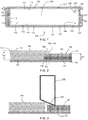
- FIG. 5 shows where the fuel cell sub-assembly 100 is located in a fuel cell formed of a plurality of layers 500.
- the fuel cell layers 500 comprise an anode flow plate 501 and a cathode flow plate 502.
- the sub-assembly 100 may be used on the anode side or the cathode side of the MEA 503.
- the gasket is thus configured to form a peripheral seal between the anode side of the MEA 503 and the anode flow plate 501 or form a peripheral seal between the cathode side of the MEA 503 and the cathode flow plate 502.
- the fuel cell sub-assembly 100a is provided on the anode side and a further fuel cell sub-assembly 100b is provided on the cathode side.
- Figure 6 shows a cross section during the assembly of the fuel cell and shows the sub-assembly 100, now numbered 100a in accordance with Figure 5 , located between the anode plate 131 and the MEA 503.
- the GDL 104 has been compressed to substantially the same width as the gasket 101, which may itself be compressed to form the seal with the anode plate 131 and the MEA 503.
- the further fuel cell sub-assembly 100b is shown lying against the cathode side of the MEA 503.
- the further fuel cell sub-assembly 100b is substantially similar to the sub assembly 100a and the same reference numerals have been used except for "500" being added to them.
- the GDL 604 comprises two planar parts 604a and 604b that are arranged face to face.
- the GDL parts 604a and 604b may have different porosities.
- the weld or projection 130 is configured to extend into both of the planar parts to hold them together with the gasket 104.
- Figure 7 shows a flowchart illustrating an example method for assembling a fuel cell using the fuel cell sub-assembly 100. The method comprises the steps of;
- a fuel cell may be formed comprising a proton exchange membrane, an anode plate, a cathode plate wherein the fuel cell sub assembly 100 is configured between the proton exchange membrane and one of the anode plate or cathode plate.
- the fuel cell may include two sub-assemblies; a first sub-assembly and a second sub-assembly, the first sub-assembly between the proton exchange membrane and the anode plate and the second sub-assembly between the proton exchange membrane and the cathode plate.
- the anode plate and cathode plate may comprise bipolar plates. A plurality of such fuel cells may be arranged together face to face to form a fuel cell stack.
Claims (15)
- Brennstoffzellen-Unterbaugruppe (100), umfassend:eine Dichtung (101), umfassend eine Umfangsabdichtung (102) für eine Brennstoffzellen-Baugruppe, wobei die Umfangsabdichtung eine zentrale Öffnung (103) der Dichtung definiert;eine Gasdiffusionsschicht (104), um diffundierte Gase einer Protonenaustauschmembran einer Brennstoffzelle bereitzustellen, wobei sich die Gasdiffusionsschicht innerhalb der zentralen Öffnung befindet;wobei an mindestens einer Verbindungsstelle (105, 106) eine nach innen weisende Oberfläche (107) der Umfangsabdichtung der Dichtung an eine entsprechende nach außen weisende Oberfläche (108) der Gasdiffusionsschicht geschweißt ist,wobei die Gasdiffusionsschicht, außer an der oder jeder Verbindungsstelle (105, 106), gleichmäßig durch einen vorbestimmten Abstand von der nach innen weisenden Oberfläche (107) der Dichtung (101) beanstandet ist, um eine Galerie zu bilden.
- Brennstoffzellen-Unterbaugruppe (100) nach Anspruch 1, wobei die Gasdiffusionsschicht konfiguriert ist, um die zentrale Öffnung (103) zu füllen.
- Brennstoffzellen-Unterbaugruppe (100) nach Anspruch 1 oder Anspruch 2, wobei die Gasdiffusionsschicht (104) eben ist und eine erste Hauptfläche (110), eine zweite Hauptfläche (111) gegenüber der ersten Hauptfläche und eine Vielzahl von Oberflächen (108, 112, 113, 114) zwischen der ersten und zweiten Hauptfläche aufweist, wobei sich die Verbindungsstelle (105, 106) auf mindestens einer der Vielzahl von Oberflächen befindet.
- Brennstoffzellen-Unterbaugruppe (100) nach einem der vorstehenden Ansprüche, wobei die Dichtung (101) einen Kanal (126) beinhaltet, der sich von seiner nach innen weisenden Oberfläche in die Umfangsabdichtung (102) erstreckt, um eine Fluidverbindung zu einer Fluidübertragungsleitung bereitzustellen, und die mindestens eine Verbindungsstelle (105, 106) zu dem Kanal benachbart ist.
- Brennstoffzellen-Unterbaugruppe (100) nach Anspruch 4, wobei die Unterbaugruppe mindestens zwei individuelle Verbindungsstellen (105, 106) beinhaltet, an denen die Dichtung (101) an die Gasdiffusionsschicht (104) geschweißt ist, wobei sich die Verbindungsstellen (105, 106) benachbart zu dem Kanal (126), auf jeder Seite davon befinden.
- Brennstoffzellen-Unterbaugruppe (100) nach einem der vorstehenden Ansprüche, wobei die Gasdiffusionsschicht (104) rechteckig ist, definiert durch vier nach außen weisende Oberflächen (108, 112, 113, 114) und die zentrale Öffnung (103) rechteckig ist, definiert durch vier nach innen weisende Oberflächen (107, 117, 118, 119) der Umfangsabdichtung (102), und sich die oder jede Verbindungsstelle (105, 106) zwischen einer Bestimmten (108) der vier Oberflächen der Gasdiffusionsschicht und einer Bestimmten (107) der vier Oberflächen der Dichtung befindet.
- Brennstoffzellen-Unterbaugruppe (100) nach einem der vorstehenden Ansprüche, wobei die Gasdiffusionsschicht (104) aus einem porösen Material besteht, mit Zwischenräumen zwischen Gasdiffusionsschichtmaterial, und an der oder jeder Verbindungsstelle (105, 106) Material der Dichtung (101) mit dem Material der Gasdiffusionsschicht (104) vermischt ist.
- Brennstoffzellen-Unterbaugruppe (100) nach Anspruch 7, wobei sich das Material der Dichtung (101) an der oder jeder Verbindungsstelle (105, 106) verjüngt, wenn es sich in die Gasdiffusionsschicht (104) hinein erstreckt und sich mit dem Gasdiffusionsschichtmaterial vermischt.
- Brennstoffzellen-Unterbaugruppe (100) nach einem der vorstehenden Ansprüche, wobei die Gasdiffusionsschicht (104) und die Dichtung (101) eben sind und eine Dicke der Gasdiffusionsschicht (104) größer ist als eine Dicke der Dichtung (101) und an der oder jeder Verbindungsstelle (105, 106) das vermischte Dichtungsmaterial und Gasdiffusionsschichtmaterial nur über einen Teil der Dicke der Gasdiffusionsschicht (104) bereitgestellt ist.
- Brennstoffzellen-Unterbaugruppe (100) nach einem der vorstehenden Ansprüche, wobei die Dichtung (101) eben ist und eine erste Hauptfläche (115), eine der ersten Hauptfläche gegenüberliegende zweite Hauptfläche (116) aufweist, wobei die Trennung zwischen der ersten und zweiten Hauptfläche (115, 116) die Dicke der Dichtung (101) definiert und wobei sich das vermischte Dichtungsmaterial und Gasdiffusionsschichtmaterial zwischen Ebenen erstrecken, die durch die erste und zweite Hauptfläche (115, 116) der Dichtung definiert sind.
- Brennstoffzellen-Unterbaugruppe (100) nach einem der vorstehenden Ansprüche, wobei die Dichtung (101) ist:i) eine Anodendichtung zum Abdichten zwischen einer Anodenströmungsplatte und einer Protonenaustauschmembran; oderii) eine Kathodendichtung zum Abdichten zwischen einer Kathodenströmungsplatte und einer Protonenaustauschmembran.
- Brennstoffzellen-Unterbaugruppe (100) nach einem der vorstehenden Ansprüche, wobei die Dichtung (101) eine Anodendichtung ist und die Unterbaugruppe eine Anodenströmungsplatte beinhaltet, die konfiguriert ist, um der Gasdiffusionsschicht (104) ein Anodengas bereitzustellen, wobei die Dichtung und die Gasdiffusionsschicht konfiguriert sind, um an einer Fläche der Anodenströmungsplatte zu liegen.
- Brennstoffzelle, umfassend eine Protonenaustauschmembran, eine Anodenströmungsplatte, die konfiguriert ist, um einer Anodengasdiffusionsschicht ein Anodengas bereitzustellen, und eine Kathodenströmungsplatte, die konfiguriert ist, um einer Kathodengasdiffusionsschicht ein Kathodengas bereitzustellen, wobei die Brennstoffzelle mindestens eine der Brennstoffzellen-Unterbaugruppen (100) nach einem der vorstehenden Ansprüche beinhaltet, wobei die Gasdiffusionsschicht (104) der Brennstoffzellen-Unterbaugruppe die Anodengasdiffusionsschicht oder die Kathodengasdiffusionsschicht bildet.
- Brennstoffzellenstapel, umfassend eine Vielzahl von Brennstoffzellen wie in Anspruch 13 definiert, die zusammen in einem Stapel angeordnet sind.
- Verfahren zum Zusammenbauen einer Brennstoffzelle unter Verwendung der Brennstoffzellen-Unterbaugruppe (100) nach einem der Ansprüche 1 bis 12, umfassend die Schritte:Aufnehmen einer Anodenströmungsplatte (501), auf der die Brennstoffzellen-Unterbaugruppe (100a) angeordneten ist;Anbringen einer Protonenaustauschmembran auf die Brennstoffzellen-Unterbaugruppe auf einer der Anodenströmungsplatte gegenüberliegenden Seite;Anbringen einer weiteren Brennstoffzellen-Unterbaugruppe (100b) auf die Protonenaustauschmembran;Anbringen einer Kathodenströmungsplatte (502) auf die weitere Brennstoffzellen-Unterbaugruppe auf einer der Protonenaustauschmembran gegenüberliegenden Seite.
Applications Claiming Priority (2)
| Application Number | Priority Date | Filing Date | Title |
|---|---|---|---|
| GB1517245.5A GB2542803B (en) | 2015-09-30 | 2015-09-30 | Fuel cell sub-assembly |
| PCT/GB2016/052964 WO2017055815A1 (en) | 2015-09-30 | 2016-09-23 | Fuel cell sub-assembly |
Publications (2)
| Publication Number | Publication Date |
|---|---|
| EP3357118A1 EP3357118A1 (de) | 2018-08-08 |
| EP3357118B1 true EP3357118B1 (de) | 2020-02-12 |
Family
ID=54544310
Family Applications (1)
| Application Number | Title | Priority Date | Filing Date |
|---|---|---|---|
| EP16787916.2A Active EP3357118B1 (de) | 2015-09-30 | 2016-09-23 | Unterbaugruppe einer brennstoffzelle |
Country Status (7)
| Country | Link |
|---|---|
| US (2) | US11056694B2 (de) |
| EP (1) | EP3357118B1 (de) |
| JP (1) | JP6965240B2 (de) |
| CN (1) | CN108352545B (de) |
| BR (1) | BR112018006118A2 (de) |
| GB (1) | GB2542803B (de) |
| WO (1) | WO2017055815A1 (de) |
Families Citing this family (6)
| Publication number | Priority date | Publication date | Assignee | Title |
|---|---|---|---|---|
| JP7053298B2 (ja) * | 2018-02-14 | 2022-04-12 | Nok株式会社 | ガス拡散層一体ガスケット及び燃料電池セル用部材 |
| CN112531183B (zh) * | 2020-12-03 | 2022-02-11 | 中国科学院大连化学物理研究所 | 燃料电池膜电极密封组件、封装工艺以及连续封装用设备 |
| GB2617714A (en) * | 2021-01-11 | 2023-10-18 | Intelligent Energy Ltd | Gas diffusion method for use with fuel cell stack |
| JP2024502251A (ja) * | 2021-01-11 | 2024-01-18 | インテリジェント エナジー リミテッド | 燃料電池スタックとともに用いるためのガス拡散方法 |
| GB2603112B (en) * | 2021-01-11 | 2023-07-26 | Intelligent Energy Ltd | Gas diffusion method for use with fuel cell stack |
| FR3132394B3 (fr) | 2022-07-25 | 2024-03-22 | Symbio France | Assemblage membrane-électrode de pile à combustible, procédé de fabrication d’un tel assemblage et pile à combustible comprenant au moins un tel assemblage |
Family Cites Families (11)
| Publication number | Priority date | Publication date | Assignee | Title |
|---|---|---|---|---|
| US20020172852A1 (en) | 2001-05-15 | 2002-11-21 | David Frank | Flow field plate for a fuel cell and fuel cell assembly incorporating the flow field plate |
| US20030082430A1 (en) * | 2001-10-25 | 2003-05-01 | Daisuke Suzuki | Fuel cell gasket assembly and method of making |
| US7186476B2 (en) * | 2003-11-07 | 2007-03-06 | General Motors Corporation | One piece bipolar plate with spring seals |
| JP5087863B2 (ja) * | 2006-06-09 | 2012-12-05 | トヨタ自動車株式会社 | 燃料電池 |
| US7732083B2 (en) * | 2006-12-15 | 2010-06-08 | 3M Innovative Properties Company | Gas diffusion layer incorporating a gasket |
| DE102007003096A1 (de) * | 2007-01-16 | 2008-07-17 | Carl Freudenberg Kg | Dichtungsanordnung für ein Plattenelement einer Brennstoffzelle |
| US7790305B2 (en) * | 2007-02-20 | 2010-09-07 | Freudenberg-Nok General Partnership | Gas diffusion layers with integrated seals having interlocking features |
| JP5681792B2 (ja) * | 2011-04-01 | 2015-03-11 | 本田技研工業株式会社 | 燃料電池用電解質膜・電極構造体及びその製造方法 |
| US20140120452A1 (en) * | 2012-05-17 | 2014-05-01 | Panasonic Corporation | Fuel cell and manufacturing method thereof |
| US9425469B2 (en) * | 2013-05-29 | 2016-08-23 | Yong Gao | Integrated gas diffusion layer with sealing function and method of making the same |
| KR101377187B1 (ko) | 2014-01-02 | 2014-03-25 | 스탠다드에너지(주) | 반응물질의 누설방지를 위한 저장 및 회수수단이 구비된 레독스 흐름전지 또는 연료전지 |
-
2015
- 2015-09-30 GB GB1517245.5A patent/GB2542803B/en active Active
-
2016
- 2016-09-23 US US15/761,345 patent/US11056694B2/en active Active
- 2016-09-23 CN CN201680062197.9A patent/CN108352545B/zh active Active
- 2016-09-23 JP JP2018515884A patent/JP6965240B2/ja active Active
- 2016-09-23 EP EP16787916.2A patent/EP3357118B1/de active Active
- 2016-09-23 BR BR112018006118A patent/BR112018006118A2/pt not_active Application Discontinuation
- 2016-09-23 WO PCT/GB2016/052964 patent/WO2017055815A1/en active Application Filing
-
2021
- 2021-07-06 US US17/368,785 patent/US20210336280A1/en not_active Abandoned
Non-Patent Citations (1)
| Title |
|---|
| None * |
Also Published As
| Publication number | Publication date |
|---|---|
| WO2017055815A1 (en) | 2017-04-06 |
| BR112018006118A2 (pt) | 2018-10-23 |
| JP6965240B2 (ja) | 2021-11-10 |
| CN108352545A (zh) | 2018-07-31 |
| US20210336280A1 (en) | 2021-10-28 |
| GB2542803A (en) | 2017-04-05 |
| EP3357118A1 (de) | 2018-08-08 |
| US11056694B2 (en) | 2021-07-06 |
| GB201517245D0 (en) | 2015-11-11 |
| JP2018534728A (ja) | 2018-11-22 |
| US20180269498A1 (en) | 2018-09-20 |
| CN108352545B (zh) | 2021-02-26 |
| GB2542803B (en) | 2022-01-12 |
Similar Documents
| Publication | Publication Date | Title |
|---|---|---|
| EP3357118B1 (de) | Unterbaugruppe einer brennstoffzelle | |
| JP5683433B2 (ja) | 燃料電池スタック | |
| CA2866234C (en) | Fuel cell with resin frame having buffer and connection channel | |
| JP5855442B2 (ja) | 燃料電池用樹脂枠付き電解質膜・電極構造体の製造方法 | |
| US20090042086A1 (en) | Fuel cell | |
| US10826083B2 (en) | Fuel cell assemblies with improved reactant flow | |
| JP5643146B2 (ja) | 燃料電池 | |
| US20080166617A1 (en) | Fuel cell and cell assembly for fuel cell | |
| JP6842421B2 (ja) | 固体ポリマー電解質燃料電池のためのシール | |
| JP6709053B2 (ja) | 樹脂枠付き段差meaの製造方法及び製造装置 | |
| EP2830130B1 (de) | Brennstoffzelle | |
| US10003098B2 (en) | Fuel cell | |
| US11171341B2 (en) | Fuel cell and method of manufacturing fuel cell | |
| US9831516B2 (en) | Fuel cell | |
| KR20200132294A (ko) | 연료전지용 탄성체 셀 프레임 및 그 제조방법과 이를 이용한 연료전지 스택 | |
| JP2020140944A (ja) | 燃料電池 | |
| JP5173641B2 (ja) | 燃料電池 | |
| JP6619646B2 (ja) | 燃料電池用ガスケット及びその製造方法 | |
| CN107534178A (zh) | 燃料电池堆 | |
| JP2013222698A (ja) | 燃料電池 | |
| JP2021009809A (ja) | 燃料電池 |
Legal Events
| Date | Code | Title | Description |
|---|---|---|---|
| STAA | Information on the status of an ep patent application or granted ep patent |
Free format text: STATUS: UNKNOWN |
|
| STAA | Information on the status of an ep patent application or granted ep patent |
Free format text: STATUS: THE INTERNATIONAL PUBLICATION HAS BEEN MADE |
|
| PUAI | Public reference made under article 153(3) epc to a published international application that has entered the european phase |
Free format text: ORIGINAL CODE: 0009012 |
|
| STAA | Information on the status of an ep patent application or granted ep patent |
Free format text: STATUS: REQUEST FOR EXAMINATION WAS MADE |
|
| 17P | Request for examination filed |
Effective date: 20180321 |
|
| AK | Designated contracting states |
Kind code of ref document: A1 Designated state(s): AL AT BE BG CH CY CZ DE DK EE ES FI FR GB GR HR HU IE IS IT LI LT LU LV MC MK MT NL NO PL PT RO RS SE SI SK SM TR |
|
| AX | Request for extension of the european patent |
Extension state: BA ME |
|
| DAV | Request for validation of the european patent (deleted) | ||
| DAX | Request for extension of the european patent (deleted) | ||
| RIC1 | Information provided on ipc code assigned before grant |
Ipc: H01M 8/0247 20160101AFI20190703BHEP Ipc: H01M 8/2483 20160101ALI20190703BHEP Ipc: H01M 8/0273 20160101ALI20190703BHEP Ipc: H01M 8/242 20160101ALI20190703BHEP Ipc: H01M 8/1018 20160101ALN20190703BHEP |
|
| GRAP | Despatch of communication of intention to grant a patent |
Free format text: ORIGINAL CODE: EPIDOSNIGR1 |
|
| STAA | Information on the status of an ep patent application or granted ep patent |
Free format text: STATUS: GRANT OF PATENT IS INTENDED |
|
| INTG | Intention to grant announced |
Effective date: 20190823 |
|
| GRAS | Grant fee paid |
Free format text: ORIGINAL CODE: EPIDOSNIGR3 |
|
| GRAA | (expected) grant |
Free format text: ORIGINAL CODE: 0009210 |
|
| STAA | Information on the status of an ep patent application or granted ep patent |
Free format text: STATUS: THE PATENT HAS BEEN GRANTED |
|
| AK | Designated contracting states |
Kind code of ref document: B1 Designated state(s): AL AT BE BG CH CY CZ DE DK EE ES FI FR GB GR HR HU IE IS IT LI LT LU LV MC MK MT NL NO PL PT RO RS SE SI SK SM TR |
|
| REG | Reference to a national code |
Ref country code: GB Ref legal event code: FG4D |
|
| REG | Reference to a national code |
Ref country code: CH Ref legal event code: EP |
|
| REG | Reference to a national code |
Ref country code: AT Ref legal event code: REF Ref document number: 1233300 Country of ref document: AT Kind code of ref document: T Effective date: 20200215 |
|
| REG | Reference to a national code |
Ref country code: DE Ref legal event code: R096 Ref document number: 602016029654 Country of ref document: DE |
|
| REG | Reference to a national code |
Ref country code: IE Ref legal event code: FG4D |
|
| PG25 | Lapsed in a contracting state [announced via postgrant information from national office to epo] |
Ref country code: NO Free format text: LAPSE BECAUSE OF FAILURE TO SUBMIT A TRANSLATION OF THE DESCRIPTION OR TO PAY THE FEE WITHIN THE PRESCRIBED TIME-LIMIT Effective date: 20200512 Ref country code: RS Free format text: LAPSE BECAUSE OF FAILURE TO SUBMIT A TRANSLATION OF THE DESCRIPTION OR TO PAY THE FEE WITHIN THE PRESCRIBED TIME-LIMIT Effective date: 20200212 Ref country code: FI Free format text: LAPSE BECAUSE OF FAILURE TO SUBMIT A TRANSLATION OF THE DESCRIPTION OR TO PAY THE FEE WITHIN THE PRESCRIBED TIME-LIMIT Effective date: 20200212 |
|
| REG | Reference to a national code |
Ref country code: LT Ref legal event code: MG4D |
|
| REG | Reference to a national code |
Ref country code: NL Ref legal event code: MP Effective date: 20200212 |
|
| PG25 | Lapsed in a contracting state [announced via postgrant information from national office to epo] |
Ref country code: IS Free format text: LAPSE BECAUSE OF FAILURE TO SUBMIT A TRANSLATION OF THE DESCRIPTION OR TO PAY THE FEE WITHIN THE PRESCRIBED TIME-LIMIT Effective date: 20200612 Ref country code: GR Free format text: LAPSE BECAUSE OF FAILURE TO SUBMIT A TRANSLATION OF THE DESCRIPTION OR TO PAY THE FEE WITHIN THE PRESCRIBED TIME-LIMIT Effective date: 20200513 Ref country code: HR Free format text: LAPSE BECAUSE OF FAILURE TO SUBMIT A TRANSLATION OF THE DESCRIPTION OR TO PAY THE FEE WITHIN THE PRESCRIBED TIME-LIMIT Effective date: 20200212 Ref country code: LV Free format text: LAPSE BECAUSE OF FAILURE TO SUBMIT A TRANSLATION OF THE DESCRIPTION OR TO PAY THE FEE WITHIN THE PRESCRIBED TIME-LIMIT Effective date: 20200212 Ref country code: SE Free format text: LAPSE BECAUSE OF FAILURE TO SUBMIT A TRANSLATION OF THE DESCRIPTION OR TO PAY THE FEE WITHIN THE PRESCRIBED TIME-LIMIT Effective date: 20200212 Ref country code: BG Free format text: LAPSE BECAUSE OF FAILURE TO SUBMIT A TRANSLATION OF THE DESCRIPTION OR TO PAY THE FEE WITHIN THE PRESCRIBED TIME-LIMIT Effective date: 20200512 |
|
| PG25 | Lapsed in a contracting state [announced via postgrant information from national office to epo] |
Ref country code: NL Free format text: LAPSE BECAUSE OF FAILURE TO SUBMIT A TRANSLATION OF THE DESCRIPTION OR TO PAY THE FEE WITHIN THE PRESCRIBED TIME-LIMIT Effective date: 20200212 |
|
| PG25 | Lapsed in a contracting state [announced via postgrant information from national office to epo] |
Ref country code: PT Free format text: LAPSE BECAUSE OF FAILURE TO SUBMIT A TRANSLATION OF THE DESCRIPTION OR TO PAY THE FEE WITHIN THE PRESCRIBED TIME-LIMIT Effective date: 20200705 Ref country code: DK Free format text: LAPSE BECAUSE OF FAILURE TO SUBMIT A TRANSLATION OF THE DESCRIPTION OR TO PAY THE FEE WITHIN THE PRESCRIBED TIME-LIMIT Effective date: 20200212 Ref country code: EE Free format text: LAPSE BECAUSE OF FAILURE TO SUBMIT A TRANSLATION OF THE DESCRIPTION OR TO PAY THE FEE WITHIN THE PRESCRIBED TIME-LIMIT Effective date: 20200212 Ref country code: ES Free format text: LAPSE BECAUSE OF FAILURE TO SUBMIT A TRANSLATION OF THE DESCRIPTION OR TO PAY THE FEE WITHIN THE PRESCRIBED TIME-LIMIT Effective date: 20200212 Ref country code: LT Free format text: LAPSE BECAUSE OF FAILURE TO SUBMIT A TRANSLATION OF THE DESCRIPTION OR TO PAY THE FEE WITHIN THE PRESCRIBED TIME-LIMIT Effective date: 20200212 Ref country code: CZ Free format text: LAPSE BECAUSE OF FAILURE TO SUBMIT A TRANSLATION OF THE DESCRIPTION OR TO PAY THE FEE WITHIN THE PRESCRIBED TIME-LIMIT Effective date: 20200212 Ref country code: RO Free format text: LAPSE BECAUSE OF FAILURE TO SUBMIT A TRANSLATION OF THE DESCRIPTION OR TO PAY THE FEE WITHIN THE PRESCRIBED TIME-LIMIT Effective date: 20200212 Ref country code: SK Free format text: LAPSE BECAUSE OF FAILURE TO SUBMIT A TRANSLATION OF THE DESCRIPTION OR TO PAY THE FEE WITHIN THE PRESCRIBED TIME-LIMIT Effective date: 20200212 Ref country code: SM Free format text: LAPSE BECAUSE OF FAILURE TO SUBMIT A TRANSLATION OF THE DESCRIPTION OR TO PAY THE FEE WITHIN THE PRESCRIBED TIME-LIMIT Effective date: 20200212 |
|
| REG | Reference to a national code |
Ref country code: DE Ref legal event code: R097 Ref document number: 602016029654 Country of ref document: DE |
|
| REG | Reference to a national code |
Ref country code: AT Ref legal event code: MK05 Ref document number: 1233300 Country of ref document: AT Kind code of ref document: T Effective date: 20200212 |
|
| PLBE | No opposition filed within time limit |
Free format text: ORIGINAL CODE: 0009261 |
|
| STAA | Information on the status of an ep patent application or granted ep patent |
Free format text: STATUS: NO OPPOSITION FILED WITHIN TIME LIMIT |
|
| 26N | No opposition filed |
Effective date: 20201113 |
|
| PG25 | Lapsed in a contracting state [announced via postgrant information from national office to epo] |
Ref country code: IT Free format text: LAPSE BECAUSE OF FAILURE TO SUBMIT A TRANSLATION OF THE DESCRIPTION OR TO PAY THE FEE WITHIN THE PRESCRIBED TIME-LIMIT Effective date: 20200212 Ref country code: AT Free format text: LAPSE BECAUSE OF FAILURE TO SUBMIT A TRANSLATION OF THE DESCRIPTION OR TO PAY THE FEE WITHIN THE PRESCRIBED TIME-LIMIT Effective date: 20200212 |
|
| PG25 | Lapsed in a contracting state [announced via postgrant information from national office to epo] |
Ref country code: SI Free format text: LAPSE BECAUSE OF FAILURE TO SUBMIT A TRANSLATION OF THE DESCRIPTION OR TO PAY THE FEE WITHIN THE PRESCRIBED TIME-LIMIT Effective date: 20200212 Ref country code: PL Free format text: LAPSE BECAUSE OF FAILURE TO SUBMIT A TRANSLATION OF THE DESCRIPTION OR TO PAY THE FEE WITHIN THE PRESCRIBED TIME-LIMIT Effective date: 20200212 |
|
| REG | Reference to a national code |
Ref country code: CH Ref legal event code: PL |
|
| REG | Reference to a national code |
Ref country code: BE Ref legal event code: MM Effective date: 20200930 |
|
| PG25 | Lapsed in a contracting state [announced via postgrant information from national office to epo] |
Ref country code: LU Free format text: LAPSE BECAUSE OF NON-PAYMENT OF DUE FEES Effective date: 20200923 |
|
| PG25 | Lapsed in a contracting state [announced via postgrant information from national office to epo] |
Ref country code: FR Free format text: LAPSE BECAUSE OF NON-PAYMENT OF DUE FEES Effective date: 20200930 |
|
| PG25 | Lapsed in a contracting state [announced via postgrant information from national office to epo] |
Ref country code: IE Free format text: LAPSE BECAUSE OF NON-PAYMENT OF DUE FEES Effective date: 20200923 Ref country code: LI Free format text: LAPSE BECAUSE OF NON-PAYMENT OF DUE FEES Effective date: 20200930 Ref country code: CH Free format text: LAPSE BECAUSE OF NON-PAYMENT OF DUE FEES Effective date: 20200930 Ref country code: BE Free format text: LAPSE BECAUSE OF NON-PAYMENT OF DUE FEES Effective date: 20200930 |
|
| PG25 | Lapsed in a contracting state [announced via postgrant information from national office to epo] |
Ref country code: TR Free format text: LAPSE BECAUSE OF FAILURE TO SUBMIT A TRANSLATION OF THE DESCRIPTION OR TO PAY THE FEE WITHIN THE PRESCRIBED TIME-LIMIT Effective date: 20200212 Ref country code: MT Free format text: LAPSE BECAUSE OF FAILURE TO SUBMIT A TRANSLATION OF THE DESCRIPTION OR TO PAY THE FEE WITHIN THE PRESCRIBED TIME-LIMIT Effective date: 20200212 Ref country code: CY Free format text: LAPSE BECAUSE OF FAILURE TO SUBMIT A TRANSLATION OF THE DESCRIPTION OR TO PAY THE FEE WITHIN THE PRESCRIBED TIME-LIMIT Effective date: 20200212 |
|
| PG25 | Lapsed in a contracting state [announced via postgrant information from national office to epo] |
Ref country code: MK Free format text: LAPSE BECAUSE OF FAILURE TO SUBMIT A TRANSLATION OF THE DESCRIPTION OR TO PAY THE FEE WITHIN THE PRESCRIBED TIME-LIMIT Effective date: 20200212 Ref country code: MC Free format text: LAPSE BECAUSE OF FAILURE TO SUBMIT A TRANSLATION OF THE DESCRIPTION OR TO PAY THE FEE WITHIN THE PRESCRIBED TIME-LIMIT Effective date: 20200212 Ref country code: AL Free format text: LAPSE BECAUSE OF FAILURE TO SUBMIT A TRANSLATION OF THE DESCRIPTION OR TO PAY THE FEE WITHIN THE PRESCRIBED TIME-LIMIT Effective date: 20200212 |
|
| PGFP | Annual fee paid to national office [announced via postgrant information from national office to epo] |
Ref country code: GB Payment date: 20230927 Year of fee payment: 8 |
|
| PGFP | Annual fee paid to national office [announced via postgrant information from national office to epo] |
Ref country code: DE Payment date: 20230927 Year of fee payment: 8 |