EP3356701B1 - Zahnrad mit schrägverzahnung und segment für ein zahnrad - Google Patents
Zahnrad mit schrägverzahnung und segment für ein zahnrad Download PDFInfo
- Publication number
- EP3356701B1 EP3356701B1 EP16757158.7A EP16757158A EP3356701B1 EP 3356701 B1 EP3356701 B1 EP 3356701B1 EP 16757158 A EP16757158 A EP 16757158A EP 3356701 B1 EP3356701 B1 EP 3356701B1
- Authority
- EP
- European Patent Office
- Prior art keywords
- gear wheel
- segment
- wheel according
- gearing
- circumferential direction
- Prior art date
- Legal status (The legal status is an assumption and is not a legal conclusion. Google has not performed a legal analysis and makes no representation as to the accuracy of the status listed.)
- Active
Links
- 229910001208 Crucible steel Inorganic materials 0.000 claims description 2
- 230000005540 biological transmission Effects 0.000 description 8
- 238000004519 manufacturing process Methods 0.000 description 4
- 239000000463 material Substances 0.000 description 2
- 230000010355 oscillation Effects 0.000 description 2
- 229910001141 Ductile iron Inorganic materials 0.000 description 1
- 238000005452 bending Methods 0.000 description 1
- 230000015572 biosynthetic process Effects 0.000 description 1
- 238000013016 damping Methods 0.000 description 1
- 238000010438 heat treatment Methods 0.000 description 1
- 238000007493 shaping process Methods 0.000 description 1
- 238000004804 winding Methods 0.000 description 1
Images

Classifications
-
- F—MECHANICAL ENGINEERING; LIGHTING; HEATING; WEAPONS; BLASTING
- F16—ENGINEERING ELEMENTS AND UNITS; GENERAL MEASURES FOR PRODUCING AND MAINTAINING EFFECTIVE FUNCTIONING OF MACHINES OR INSTALLATIONS; THERMAL INSULATION IN GENERAL
- F16H—GEARING
- F16H55/00—Elements with teeth or friction surfaces for conveying motion; Worms, pulleys or sheaves for gearing mechanisms
- F16H55/02—Toothed members; Worms
- F16H55/12—Toothed members; Worms with body or rim assembled out of detachable parts
-
- F—MECHANICAL ENGINEERING; LIGHTING; HEATING; WEAPONS; BLASTING
- F16—ENGINEERING ELEMENTS AND UNITS; GENERAL MEASURES FOR PRODUCING AND MAINTAINING EFFECTIVE FUNCTIONING OF MACHINES OR INSTALLATIONS; THERMAL INSULATION IN GENERAL
- F16H—GEARING
- F16H55/00—Elements with teeth or friction surfaces for conveying motion; Worms, pulleys or sheaves for gearing mechanisms
- F16H55/02—Toothed members; Worms
- F16H55/17—Toothed wheels
Definitions
- the invention relates to a gear with helical teeth and a segment for a gear.
- the invention is therefore based on the object of reducing the formation of noise when the teeth are in mesh.
- the helical toothed wheel which is composed of segments, wherein each segment has a toothing section which has a helical toothing, wherein in each segment the toothed section is connected to the connecting area via first and second webs and connecting sections, wherein the connecting sections, the first and the second webs are each spaced apart from one another or at least partially spaced apart from one another, in particular so that the segment has several, in particular three or more, axially continuous recesses, in particular with the axial region covered by the first webs being spaced apart from the axial region covered by the second webs, in particular so that the segment has at least one recess which is continuous in the circumferential direction.
- the gear is composed of segments in the circumferential direction, each segment representing a circumferential section, that is to say a circumferential angle range of the gear.
- the segment is cut out of the gearwheel, so to speak, by means of a cutting plane which extends in the axial direction and in the radial direction from the gearwheel axis.
- the toothing in the prior art is designed as a straight toothing, since otherwise teeth would be cut and there would be a risk of tooth breakage.
- helical teeth are provided on a toothed section.
- the toothed section is cut or delimited along a tooth gap.
- the toothed section has an interface which extends with a helix angle according to the helix angle of the toothing.
- such interfaces of adjacent segments are spaced apart, that is to say they are carried out without force transmission, and the connection or the associated force flow is only carried out in the region of the contact surfaces which are arranged on the connecting sections.
- the contact surface is in each case composed of flange surfaces which each run exclusively radially and axially, that is to say not in the circumferential direction.
- first and second webs, toothed section, connecting sections and connecting area are made in one piece and / or in one piece for each segment.
- the advantage here is that the segment has a high load-bearing capacity and can be machined in one setting, and thus the relative spacing of the drill holes can also be produced very precisely for the toothing.
- the first and the second webs are curved, in particular convexly curved, in particular the first webs axially forwards and the second webs axially backwards.
- a first connecting section is arranged on the end region of the segment arranged at the front in the circumferential direction, in particular and a second connecting section is arranged on the end region of the segment arranged at the rear in the circumferential direction, wherein the first connection section has a contact surface with which the segment bears on the next adjacent segment, in particular on the corresponding contact surface of the second connection section of the next adjacent segment, the contact surface being stepped so that it has at least three even, in particular therefore flat, flange surfaces, wherein each of the flange surfaces is arranged on a respective circumferential angle position and covers a respective axial area, these respective axial areas are each spaced apart from one another or at most adjacent to one another, in particular wherein the respective axial areas do not overlap one another, the circumferential angular positions of the flange surfaces being spaced apart, in particular increasing strictly monotonously in the circumferential direction with increasing axial position of the flange surfaces.
- the toothing is an external toothing.
- the advantage here is that the manufacture is easy to carry out.
- the toothed section has at its end regions arranged in the circumferential direction in each case a first boundary surface facing the adjacent segment, which runs parallel to a tooth gap of the toothing, in particular, the first interface extending in the radial direction and along a helical line, the helical axis of which is the gear wheel axis and the helix angle of which corresponds to the helix angle of the toothing.
- the advantage here is that a helical toothing can be provided in the toothing section, which runs without interrupted teeth and is therefore very resilient.
- the toothed section in particular with a section containing a section of the first interface, protrudes circumferentially over the connecting section, in particular wherein the toothed section, in particular with another section containing another section of the first interface, extends less far in the circumferential direction than the connecting section.
- the advantage here is that the connecting section is cut or limited differently in its end region lying in the circumferential direction than the toothed section. This is because the connecting section is limited at a circumferential position, ie it extends with its end face here only in the radial and axial directions; however, the toothed section is limited according to a helical toothing, that is to say extends according to a helix and radially from the gearwheel axis.
- the connecting section has a second boundary surface which extends in the circumferential direction and in the axial direction and radially opposes the radial inside of the section of the toothed section of the adjacent segment which projects beyond the associated connecting section in the circumferential direction.
- a first distance is carried out between the first interfaces of two adjacent segments.
- a second distance is provided between the second interface and the radial inside of the protruding section of the toothed section of the adjacent segment.
- the connecting section has a connecting surface on which the corresponding connecting surface of the respectively adjacent segment is pressed on using connecting screws.
- the respective flange surface extends in the radial direction and in the axial direction, but in particular not in the circumferential direction, in particular it is therefore arranged in a single circumferential position.
- the advantage here is that the respective flange surface is simple and inexpensive to manufacture.
- a second flange surface is arranged in the axial direction between a first and a third flange surface, wherein the first and third flange surfaces each have a drill hole for a screw for aligning the segments to one another.
- the webs are arranged in a smaller radial distance range than the toothed section. It is advantageous that the webs carry the radially attached toothed section and the connecting screws for connecting the connecting sections of the adjacent segments do not break through or otherwise hinder the toothing of the gearwheel, since they are also arranged at a smaller radial distance than the toothing section and axially between the first and have space for the second webs.
- the segment has a connecting region for connecting to a drum or shaft, the gearwheel being arranged at a greater radial distance than the drum or shaft.
- a step is arranged in each case between the flange surfaces closest to one another in the axial direction. wherein there is an axial distance, in particular an air gap, between the respective step of the segment and a corresponding step of the next adjacent segment.
- the quotient of the first distance and the outer diameter of the gear is less than 0.0005, in particular less than 0.00025 or even less than 0.000125, and / or that the quotient of the second distance and the outer diameter of the gear is less than 0.0005, in particular less than 0.00025 or even less than 0.000125.
- the segment is made of ADI or GGG cast steel.
- the advantage here is that the toothing is highly resilient.
- ADI is a material based on spheroidal graphite cast iron.
- a special heat treatment achieves high strength with good elongation, high wear resistance with consistently good damping.
- the protruding region of the toothed section that is to say which projects beyond the connecting section in the circumferential direction, is thus resilient since ADI has a high strength.
- the gearing in this area is therefore highly resilient, even though the area protrudes.
- the gear wheel is therefore composed of segments of the same design, that is to say of identical segments.
- Each segment has a toothed section 1, which is designed as a cylinder jacket section provided with external toothing.
- the toothed sections 1 are similar to rack segments, the rod being curved in accordance with the lateral surface of a cylinder corresponding to the gear.
- the circumferential direction referred to here relates to the gear, that is to say the circumferential direction of the gear.
- the radial distance is related to the center of the gear, that is, it can be determined as the distance from the axis of rotation of the gear.
- the axial direction is a direction parallel to the direction of the axis of rotation.
- the toothed sections 1 can thus be produced by producing a jacket section of a hollow cylinder and by integrating a toothing into its outside.
- the jacket section is delimited in the axial direction by two planes, in particular end-face sections of the gear wheel, the normal thereof parallel to the axial direction of the gear, that is, the axial direction.
- the toothed section 1 is delimited in the circumferential direction by an interface 40 and a flange surface which has a plurality of surface sections (24, 25, 26, 27, 28, 29). Adjacent to the interface 40 is the interface 41, the normal of which is oriented in the radial direction.
- a connecting region 3 which extends in the circumferential direction, is provided for fastening on the outer surface of a drum.
- the toothed section 1 is connected to the connection area 3 via webs (22, 23).
- First webs 22 are arranged axially at the front and second webs 23 are arranged axially at the rear.
- the first webs 22 are axially spaced from the second webs 23.
- Exactly a second web 23 is preferably assigned to each first web 22, this respective first web 22 and the respectively assigned second web 23 being arranged in the same circumferential angle range.
- the first webs 22 are regularly spaced apart from one another in the circumferential direction, that is to say in the circumferential direction of the gearwheel.
- the second webs 23 are thus regularly spaced apart from one another in the circumferential direction, that is to say in the circumferential direction of the gearwheel.
- a recess made continuously in the axial direction is arranged between each two first webs 22 which are next to each other.
- a recess made continuously in the axial direction is arranged between each two second webs 23 which are next to each other.
- first webs 22 and the second webs 23 are each provided with a bending region, so that they are bent axially outwards and are therefore convex. This is because the cavity in the segment axially between the first and second webs (22, 23) is enlarged in this way and is therefore suitable for accommodating large connecting screws and for making available a sufficiently large free space, which can also be used, for example, to actuate the connecting screws screw connection to be produced is suitably designed.
- the cavity is designed such that it is also continuous in the circumferential direction through the segment.
- the cavity is also continuous in the axial direction at least at the angular position regions not covered by the webs (22, 23) and connecting sections 2.
- the connecting section 2 of a first segment which is in the circumferential direction, bears against the connecting section 2 of a further segment, which is the rear in the circumferential direction.
- the contact surface which is arranged at the front in the circumferential direction, is designed in a stepped manner so that it is composed of three flange surfaces (24, 25, 26) which are each planar, that is to say planar.
- Each of the flange surfaces (24, 25, 26) is arranged on a respective circumferential angle position and covers a respective axial area. These respective axial areas are each spaced apart from one another or at most adjacent to one another. The respective axial areas therefore do not overlap.
- the circumferential angular positions of the flange surfaces (25, 26, 24) are spaced apart from one another and increase in the circumferential direction with increasing axial position of the flange surfaces (24, 25, 26).
- the contact surface arranged at the rear in the circumferential direction is designed in a stepped manner so that its flat, that is to say flat, flange surfaces (27, 28, 29) each abut a respective flange surface (24, 25, 26) of the next adjacent segment.
- the flange surfaces (24, 25, 26, 27, 28, 29) have drill holes 20 for connecting screws and the axially outer flange surfaces (24, 26, 27, 29) each have at least one drill hole 21 for centering screws or screws for aligning the segments with one another .
- a contact of the flange surface 24 against the flange surface 29, a contact of the flange surface 25 against the flange surface 28 and a contact of the flange surface 26 against the flange surface 27 can be achieved and the segments can be aligned with one another by means of the centering screws. The segments are then connected to one another by inserting the connecting screws.
- the above-mentioned cavity which is continuous in the circumferential direction and at least partially in the axial direction, offers sufficient space for actuating the screw connections, for example for attaching and actuating the screw heads, using a tool.
- the bulbous, that is to say convex, design of the webs 22 also increases this space.
- the interface 40 of the toothed section 1 of the segment also lies in contact with a corresponding interface 40 of the toothed section 1 of the next adjacent segment.
- the adjacent segment with its corresponding connecting section 2 is screwed onto the connecting section 2 of a respective segment.
- the connecting section 2 extends in the radial and in the axial direction.
- the entire connecting section 2 is thus located in a circumferential winding area.
- the boreholes (20, 21) oriented in the circumferential direction are arranged in the connecting surface.
- Drilled holes 20 are provided for inserting screws, with which the respectively adjacent segments are pressed against one another.
- at least one drill hole 21 is also provided for introducing a screw for aligning the segments relative to one another. Alignment of the segments is thus made possible before the connecting screws are firmly tightened. After the alignment has been carried out, the connecting screws are firmly screwed on, thus fixing the relative position of the segments.
- the toothing section 1 has a toothing on its radially outer side.
- the teeth are designed as helical teeth.
- the Boundary surface 40 with which the toothing section 1 of the segment adjoins the correspondingly adjacent one, is designed along a gap in the toothing. Thus, none of the teeth is cut through the interface 40.
- the interface 40 thus extends in accordance with the helical toothing, that is, a helical section, and in the radial direction. In a first approximation, it can be viewed as a plan.
- the toothed section 1 protrudes in sections over the connecting section 2.
- the toothed section 1 protrudes at least in a first axial region over the flange surface 26 in the circumferential direction; in a second axial region, the toothed section 1 is retracted in the circumferential direction, so that the interface 41 is visible.
- the boundary surface 41 extends in the axial direction and in the circumferential direction; so it has a single radial distance.
- the segments are tolerated and designed in such a way that two adjacent segments touch on their flange surfaces (24, 25, 26, 27, 28, 29), but there is a distance in the area of the interfaces 40 and 41.
- a distance of less than 1 mm, in particular less than 0.5 mm is preferably maintained with an outer diameter of the gear wheel composed of the segments of more than 2 meters, in particular of more than 4 meters.
- the quotient of distance and outer diameter is therefore less than 0.0005, in particular less than 0.00025 or even 0.000125.
- the protruding part of the toothing section 1 covers the interface 41 of the adjacent segment, in particular in the radial direction.
- the interfaces 40 of two adjacent segments lie opposite each other in the circumferential direction and also in the axial direction.
- the gear wheel is not designed with helical teeth but with straight teeth.
- the interface 41 is then preferably omitted. Nevertheless, however, there remains a very narrow air gap between the interfaces 40 of the next adjacent segments facing each other.
Landscapes
- Engineering & Computer Science (AREA)
- General Engineering & Computer Science (AREA)
- Mechanical Engineering (AREA)
- Gears, Cams (AREA)
Description
- Die Erfindung betrifft ein Zahnrad mit Schrägverzahnung und ein Segment für ein Zahnrad.
- Aus der
WO 2013/020639 A1 ist ein segmentiertes Zahnrad bekannt. - Aus der
CN 203 209 919 U ist ein segmentiertes Zahnrad bekannt. - Aus der
CN 103 934 651 A ist ebenfalls ein solches Zahnrad bekannt. - Aus der gattungsgemäßen
WO 2013/020639 A1 und aus derCN 202 520 903 U ist ein segmentiertes Zahnrad mit Schrägverzahnung bekannt. - Der Erfindung liegt daher die Aufgabe zugrunde, die Geräuschbildung bei im Eingriff stehenden Verzahnungen zu vermindern.
- Erfindungsgemäß wird die Aufgabe bei dem Zahnrad nach den in Anspruch 1 angegebenen Merkmalen gelöst.
- Wichtige Merkmale der Erfindung bei dem Zahnrad mit Schrägverzahnung, welches aus Segmenten zusammengesetzt ist,
wobei jedes Segment einen Verzahnungsabschnitt aufweist, der eine Schrägverzahnung aufweist,
wobei bei jedem Segment der Verzahnungsabschnitt über erste und zweite Stege sowie Verbindungsabschnitte mit dem Verbindungsbereich verbunden ist,
wobei die Verbindungsabschnitte, die ersten und die zweiten Stege jeweils beabstandet voneinander sind oder zumindest abschnittsweise voneinander beabstandet sind,
insbesondere so dass das Segment mehrere, insbesondere drei oder mehr, axial durchgehende Ausnehmungen aufweist,
insbesondere wobei der von den ersten Stegen überdeckte axiale Bereich beabstandet ist von dem von den zweiten Stegen überdeckten axialen Bereich, insbesondere so dass das Segment zumindest eine in Umfangsrichtung durchgehende Ausnehmung aufweist. - Von Vorteil ist dabei, dass mittels der Schrägverzahnung mit einem in Eingriff stehenden Verzahnungsteil Drehmoment geräuscharm übertragbar ist, obwohl das Zahnrad aus Segmenten zusammengesetzt ist.
- Denn bei einem segmentierten Zahnrad nach Stand der Technik ist das Zahnrad in Umfangsrichtung aus Segmenten zusammengesetzt, wobei jedes Segment einen Umfangsabschnitt, also einen Umfangswinkelberiech des Zahnrades darstellt. Das Segment ist sozusagen mittels einer Schnittebene herausgeschnitten aus dem Zahnrad, welche sich in axialer und in von der Zahnradachse aus radialer Richtung erstreckt. Somit ist die Verzahnung im Stand der Technik als Geradverzahnung auszuführen, da ansonsten Zähne angeschnitten wären und somit Zahnbruchgefahr bestehen würde.
- Bei der Erfindung hingegen wird eine Schrägverzahnung auf einem Verzahnungsabschnitt vorgesehen. Der Verzahnungsabschnitt ist entlang einer Zahnlücke abgeschnitten oder begrenzt. Auf diese Weise ist ein geräuscharmer Betrieb des Zahnrades ermöglicht, wobei allerdings der Verzahnungsabschnitt eine Grenzfläche hat, welche mit einem Schrägungswinkel gemäß dem Schrägungswinkel der Verzahnung verläuft. Erfindungsgemäß werden solche Grenzflächen benachbarter Segmente beabstandet, also ohne Kraftübertragung ausgeführt und die Verbindung beziehungsweise der zugehörige Kraftfluss nur im Bereich der Anlageflächen ausgeführt, die an den Verbindungsabschnitten angeordnet sind.
- Die Anlagefläche ist jeweils aus Flanschflächen zusammengesetzt, welche jeweils ausschließlich radial und axial verlaufen, also nicht in Umfangsrichtung.
- Die Flanschflächen des jeweiligen Segments liegen somit an entsprechenden Flanschflächen des jeweils nächstbenachbarten Segments an. Somit ist in Umfangsrichtung ein spielfreies Anliegen realisiert. Allerdings ist in axialer Richtung kein Anliegen von Flächen realisiert. Denn die zwischen den Flanschflächen angeordneten Stufen sind jeweils voneinander über einen Luftspalt beabstandet. Auch in radialer Richtung ist ein formschlüssiges Anliegen nicht realisiert. Auf diese Weise ist also eine Übertragung von Schall, dessen Schwingungsmode in Umfangsrichtung ohne wesentliche Verluste von einem Segment zum nächstbenachbarten Segment übertragbar, jedoch sind andere Schwingungsmoden stark abgedämpft, da in radialer und in axialer Richtung kein formschlüssiges Anliegen der Segmente aneinander realisiert ist. Somit ist eine geringere Geräuschbildung erreichbar, insbesondere im Vergleich zu einem einstückig ausgeführten Zahnrad.
- Bei einer vorteilhaften Ausgestaltung sind bei jedem Segment erste und zweite Stege, Verzahnungsabschnitt, Verbindungsabschnitte und Verbindungsbereich einteilig und/oder einstückig ausgeführt. Von Vorteil ist dabei, dass das Segment eine hohe Belastbarkeit aufweist und in einer Aufspannung bearbeitbar ist und somit die relative Beabstandung der Bohrlöcher auch zur Verzahnung sehr präzise herstellbar ist.
- Bei einer beanspruchten Ausgestaltung sind die ersten und die zweiten Stege gebogen ausgeführt, insbesondere konvex gekrümmt, insbesondere die ersten Stege nach axial vorne und die zweiten Stege nach axial hinten. Von Vorteil ist dabei, dass die Tragfähigkeit des Segments bei geringem Materialeinsatz und somit geringem Bearbeitungsaufwand erhöht ist. Bei einer vorteilhaften Ausgestaltung ist ein erster Verbindungsabschnitt am in Umfangsrichtung vorne angeordneten Endbereich des Segments angeordnet,
insbesondere und ein zweiter Verbindungsabschnitt am in Umfangsrichtung hinten angeordneten Endbereich des Segments angeordnet ist,
wobei der der erste Verbindungsabschnitt eine Anlagefläche aufweist, mit welcher das Segment am nächstbenachbarten Segment, insbesondere an der entsprechenden Anlagefläche des zweiten Verbindungsabschnitts des nächstbenachbarten Segments, anliegt,
wobei die Anlagefläche gestuft ausgeführt ist, so dass sie zumindest drei eben, insbesondere also plan, ausgeführten Flanschflächen aufweist,
wobei jede der Flanschflächen dabei auf einer jeweiligen Umfangswinkelposition angeordnet ist und einen jeweiligen axialen Bereich überdeckt,
wobei sind diese jeweiligen axialen Bereiche jeweils voneinander beabstandet oder höchstens aneinander angrenzend angeordnet sind, insbesondere wobei die jeweiligen axialen Bereiche nicht einander überlappen,
wobei die Umfangswinkelpositionen der Flanschflächen voneinander beabstandet sind, insbesondere in Umfangsrichtung streng monoton ansteigen mit zunehmender Axialposition der Flanschflächen. Von Vorteil ist dabei, dass das Ausrichten der Segmente zueinander vereinfacht ist und in axialer Richtung ein Formschluss vorhanden ist. - Bei einer vorteilhaften Ausgestaltung ist die Verzahnung eine Außenverzahnung. Von Vorteil ist dabei, dass die Herstellung einfach ausführbar ist.
- Bei einer vorteilhaften Ausgestaltung weist der Verzahnungsabschnitt an seinen in Umfangsrichtung angeordneten Endbereichen jeweils eine zum benachbarten Segment zugewandte erste Grenzfläche auf, welche parallel zu einer Zahnlücke der Verzahnung verläuft,
insbesondere wobei die erste Grenzfläche sich in radialer Richtung und entlang einer Schraubenlinie, deren Schraubenachse die Zahnradachse ist und deren Schrägungswinkel dem Schrägungswinkel der Verzahnung entspricht, erstreckt. Von Vorteil ist dabei, dass eine Schrägverzahnung im Verzahnungsabschnitt vorsehbar ist, welche ohne unterbrochene Zähne verläuft und somit sehr belastbar ist. - Bei einer vorteilhaften Ausgestaltung ragt der Verzahnungsabschnitt, insbesondere mit einem einen Abschnitt der ersten Grenzfläche enthaltenden Abschnitt, in Umfangsrichtung über den Verbindungsabschnitt heraus,
insbesondere wobei der Verzahnungsabschnitt, insbesondere mit einem einen anderen Abschnitt der ersten Grenzfläche enthaltenden anderen Abschnitt, in Umfangsrichtung weniger weit sich erstreckt als der Verbindungsabschnitt. Von Vorteil ist dabei, dass der Verbindungsabschnitt in seinem in Umfangsrichtung liegenden Endbereich anders geschnitten beziehungsweise begrenzt ist als der Verzahnungsabschnitt. Denn der Verbindungsabschnitt ist an einer Umfangsposition begrenzt, erstreckt sich also mit seiner Endfläche hier nur in radialer und axialer Richtung; der Verzahnungsabschnitt jedoch ist gemäß einer Schrägverzahnung beschränkt, erstreckt sich also gemäß einer Schraubenlinie und radial von der Zahnradachse aus. - Bei einer vorteilhaften Ausgestaltung weist der Verbindungsabschnitt eine zweite Grenzfläche auf, welche in Umfangsrichtung und in axialer Richtung sich erstreckt und der radialen Innenseite des in Umfangsrichtung über den zugehörigen Verbindungsabschnitt herausragenden Abschnitts des Verzahnungsabschnitts des benachbarten Segments radial gegenübersteht. Von Vorteil ist dabei, die Verbindung besonders einfach herstellbar und präzise ausführbar zu machen.
- Bei einer vorteilhaften Ausgestaltung ist zwischen den ersten Grenzflächen zweier benachbarter Segmente ein erster Abstand ausgeführt. Von Vorteil ist dabei, dass keine direkte Kraftübertragung zwischen den Verzahnungsabschnitten zweier benachbarter Segmente stattfindet.
- Bei einer vorteilhaften Ausgestaltung ist zwischen der zweiten Grenzfläche und der radialen Innenseite des herausragenden Abschnitts des Verzahnungsabschnitts des benachbarten Segments ein zweiter Abstand vorgesehen. Von Vorteil ist dabei, dass keine direkte Kraftübertragung zwischen der Verbindungsabschnitt und dem Verzahnungsabschnitt des benachbarten Segments stattfindet.
- Bei einer vorteilhaften Ausgestaltung weist der Verbindungsabschnitt eine Verbindungsfläche auf, an der die entsprechende Verbindungsfläche des jeweils benachbarten Segments angedrückt wird mittels Verbindungsschrauben. Von Vorteil ist dabei, dass die Kraftübertragung zwischen den Verbindungsabschnitten ausgeführt wird und hierbei an einer Umfangsposition eine tragfähige Verbindung ausführbar ist. die jeweiligen Flanschflächen sich berühren und aneinander drückbar sind von den Verbindungsschrauben zur Kraftübertragung.
- Bei einer vorteilhaften Ausgestaltung erstreckt die jeweilige Flanschfläche sich in radialer Richtung und in axialer Richtung, insbesondere nicht aber in Umfangsrichtung, insbesondere ist sie also jeweils an einer einzigen Umfangsposition angeordnet. Von Vorteil ist dabei, dass die jeweilige Flanschfläche einfach und kostengünstig herstellbar ist.
- Bei einer vorteilhaften Ausgestaltung ist in axialer Richtung zwischen einer ersten und einer dritten Flanschfläche eine zweite Flanschfläche angeordnet,
wobei die erste und dritte Flanschfläche jeweils ein Bohrloch für eine Schraube zum Ausrichten der Segmente zueinander aufweist. Von Vorteil ist dabei, dass ein exaktes Ausrichten und dann ein nachfolgendes Anziehen der Schrauben ermöglicht ist. Somit ist die Kraftübertragung zwischen den Verbindungsabschnitten und nicht zwischen den Verzahnungsabschnitten ermöglicht. - Bei einer vorteilhaften Ausgestaltung sind die Stege in einem geringeren Radialabstandsbereich angeordnet als der Verzahnungsabschnitt. Von Vorteil ist dabei, dass die Stege den radial aufgesetzten Verzahnungsabschnitt tragen und die Verbindungsschrauben zur Verbindung der Verbindungsabschnitte der benachbarten Segmente die Verzahnung des Zahnrades nicht durchbrechen oder anderweitig behindern, da sie auch auf kleinerem Radialabstand angeordnet sind als der Verzahnungsabschnitt und axial zwischen den ersten und zweiten Stegen Platz haben.
- Bei einer vorteilhaften Ausgestaltung weist das Segment einen Verbindungsbereich zum Verbinden mit einer Trommel oder Welle auf, wobei das Zahnrad auf größerem Radialabstand als die Trommel beziehungsweise Welle angeordnet ist. Von Vorteil ist dabei, dass eine Trommel an ihrem Außenumfangs mit einem großen Zahnrad versehbar ist, so dass ein großes Drehmoment übertragbar ist.
- Bei einer vorteilhaften Ausgestaltung ist zwischen den in axialer Richtung zueinander nächstbenachbarten Flanschflächen jeweils eine Stufe angeordnet,
wobei zwischen der jeweiligen Stufe des Segments und einer entsprechenden Stufe des jeweils nächstbenachbarten Segments ein axialer Abstand, insbesondere also Luftspalt vorhanden ist. Von Vorteil ist dabei, dass eine einfache Herstellung ausführbar ist. - Bei einer vorteilhaften Ausgestaltung ist der Quotient aus dem ersten Abstand und dem Außendurchmesser des Zahnrades kleiner als 0,0005, insbesondere kleiner als 0,00025 oder sogar kleiner als 0,000125,
und/oder dass
der Quotient aus dem zweiten Abstand und dem Außendurchmesser des Zahnrades kleiner ist als 0,0005, insbesondere kleiner als 0,00025 oder sogar kleiner als 0,000125, ist. Von Vorteil ist dabei, dass im Rahmen der Fertigungstoleranzen und thermisch bedingten Ausdehnungen eine Kraftübertragung sicher verhinderbar ist und trotz der Abstände ein geräuscharmer Betrieb ermöglicht ist. Denn die Abstände sind außerhalb des Eingriffsbereichs der Zähne, da der durch die Abstände erzeugte Schlitz der Zahnlücke, insbesondere also dem Boden der Zahnlücke, entlang verläuft. - Wichtige Merkmale bei dem Segment sind, dass das Segment aus ADI oder GGG Stahlguss gefertigt ist. Von Vorteil ist dabei, dass die Verzahnung hoch belastbar ist. Denn ADI ist ein Werkstoff auf Basis von Gusseisen mit Kugelgraphit. Durch eine besondere Wärmebehandlung werden eine hohe Festigkeit bei guter Dehnung, ein hoher Verschleißwiderstand bei gleich bleibend guter Dämpfung erreicht.
- Der herausragende, also den Verbindungsabschnitt in Umfangsrichtung überragende Bereich des Verzahnungsabschnitts ist somit belastbar, da ADI eine hohe Festigkeit aufweist. Die Verzahnung in diesem Bereich wird also hoch belastbar, obwohl der Bereich herauskragt.
- Weitere Vorteile ergeben sich aus den Unteransprüchen.
- Die Erfindung wird nun anhand von Abbildungen näher erläutert:
- In der
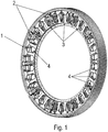
Figur 1 ist ein schrägverzahntes Zahnrad gezeigt, welches aus in Umfangsrichtung hintereinander angeordneten, gleichartig ausgeführten Segmenten zusammengesetzt ist. - In der
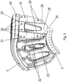
Figur 2 sind zwei der Segmente voneinander gelöst und in Schrägansicht gezeigt. - In der
Figur 3 ist das erste der beiden Segmente gezeigt. - In der
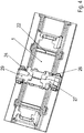
Figur 4 ist eine Draufsicht auf einen tangentialen Schnitt im Verbindungsbereich der beiden Segmente des Zahnrads gezeigt. - Das Zahnrad ist also aus gleichartig ausgeführten Segmenten zusammengesetzt, also aus identischen Segmenten.
- Jedes Segment weist einen Verzahnungsabschnitt 1 auf, welcher als mit einer Außenverzahnung versehener Zylindermantelabschnitt ausgebildet ist.
- Da in Umfangsrichtung zum Zusammensetzen des Zahnrades zehn Segmente verwendet werden, ähneln die Verzahnungsabschnitte 1 Zahnstangensegmenten, wobei die Stange entsprechend der Mantelfläche eines dem Zahnrad entsprechenden Zylinders gekrümmt ausgeführt ist.
- Die hier genannte Umfangsrichtung bezieht sich auf das Zahnrad, ist also die Umfangsrichtung des Zahnrades. Der Radialabstand ist auf die Mitte des Zahnrades bezogen, also als Abstand von der Drehachse des Zahnrades bestimmbar. Die axiale Richtung ist eine zur Richtung der Drehachse parallel gerichtete Richtung.
- Die Verzahnungsabschnitte 1 sind also herstellbar, indem ein Mantelabschnitt eines Hohlzylinders gefertigt wird und in seine Außenseite eine Verzahnung eingearbeitet wird. Dabei ist der Mantelabschnitt in axialer Richtung durch zwei Ebenen, insbesondere also Stirnflächenabschnitte des Zahnrades, begrenzt, deren Normale parallel zur Achsrichtung des Zahnrades, also axialen Richtung, ausgerichtet ist. Außerdem ist der Verzahnungsabschnitt 1 in Umfangsrichtung begrenzt durch eine Grenzfläche 40 und eine Flanschfläche, die mehrere Flächenabschnitte (24, 25, 26, 27, 28, 29) aufweist. Angrenzend an die Grenzfläche 40 ist die Grenzfläche 41 angeordnet, deren Normale in radialer Richtung ausgerichtet ist.
- An der radialen Innenseite des Segments ist ein in Umfangsrichtung sich erstreckender Verbindungsbereich 3 für das Befestigen auf der Außenfläche einer Trommel vorgesehen.
- Bei jedem Segment ist der Verzahnungsabschnitt 1 über Stege (22, 23) mit dem Verbindungsbereich 3 verbunden. Dabei sind erste Stege 22 axial vorne und zweite Stege 23 axial hinten angeordnet. Somit sind die ersten Stege 22 von den zweiten Stegen 23 axial beabstandet. Vorzugsweise ist jedem ersten Steg 22 jeweils genau ein zweiter Steg 23 zugeordnet, wobei dieser jeweilige erste Steg 22 und der jeweils zugeordnete zweite Steg 23 im jeweils selben Umfangswinkelbereich angeordnet sind.
- Die ersten Stege 22 sind in Umfangsrichtung, also in Umfangsrichtung des Zahnrades, regelmäßig voneinander beabstandet. Somit sind die zweiten Stege 23 in Umfangsrichtung, also in Umfangsrichtung des Zahnrades, regelmäßig voneinander beabstandet.
- Zwischen jeweils zwei zueinander nächstbenachbarten ersten Stegen 22 ist jeweils eine in axialer Richtung durchgehend ausgeführte Ausnehmung angeordnet.
- Zwischen jeweils zwei zueinander nächstbenachbarten zweiten Stegen 23 ist jeweils eine in axialer Richtung durchgehend ausgeführte Ausnehmung angeordnet.
- Darüber hinaus sind die ersten Stege 22 und die zweiten Stege 23 jeweils mit einem Biegebereich vorgesehen, so dass sie nach axial außen gebogen und somit konvex ausgeführt sind. Denn der im Segment axial zwischen den ersten und zweiten Stegen (22, 23) ausgeführte Hohlraum ist auf diese Weise vergrößert und daher geeignet, große Verbindungsschrauben aufzunehmen und einen genügend großen freien Raumbereich zur Verfügung zu stellen, der beispielsweise auch zur Betätigung der mit den Verbindungsschrauben herzustellenden Schraubverbindung geeignet ausgeführt ist.
- Der Hohlraum ist dabei derart ausgeführt, dass er auch in Umfangsrichtung durch das Segment durchgehend ausgeführt ist. Infolge der genannten Ausformung der ersten und zweiten Stege (2, 23) ist der Hohlraum auch in axialer Richtung zumindest an den nicht von den Stegen (22, 23) und Verbindungsabschnitten 2 überdeckten Winkelpositionsbereichen durchgehend.
- Der in Umfangsrichtung vordere Verbindungsabschnitt 2 eines ersten Segments liegt an dem in Umfangsrichtung hinteren Verbindungsabschnitt 2 eines weiteren Segments an.
- Dabei ist die in Umfangsrichtung vorne angeordnete Anlagefläche gestuft ausgeführt, so dass sie aus drei, jeweils eben, also plan, ausgeführten Flanschflächen (24, 25, 26) zusammengesetzt ist. Jede der Flanschflächen (24, 25, 26) ist dabei auf einer jeweiligen Umfangswinkelposition angeordnet und überdeckt einen jeweiligen axialen Bereich. Dabei sind diese jeweiligen axialen Beriech jeweils voneinander beabstandet oder höchstens aneinander angrenzend angeordnet. Somit überlappen die jeweiligen axialen Bereiche nicht. Die Umfangswinkelpositionen der Flanschflächen (25, 26, 24) sind voneinander beabstandet und steigen in Umfangsrichtung an mit zunehmender Axialposition der Flanschflächen (24, 25, 26).
- Die in Umfangsrichtung hinten angeordnete Anlagefläche ist entsprechend gestuft ausgeführt, so dass deren ebene, also plane Flanschflächen (27, 28, 29) jeweils an einer jeweiligen Flanschfläche (24, 25, 26) des nächstbenachbarten Segments anliegen.
- Die Flanschflächen (24, 25, 26, 27, 28, 29) weisen Bohrlöcher 20 für Verbindungsschrauben und die axial äußeren Flanschflächen (24, 26, 27, 29) weisen jeweils zumindest ein Bohrloch 21 für Zentrierschrauben oder Schrauben zum Ausrichten der Segmente zueinander auf.
- Somit ist ein Anliegen der Flanschfläche 24 an der Flanschfläche 29, ein Anliegen der Flanschfläche 25 an der Flanschfläche 28 und ein Anliegen der Flanschfläche 26 an der Flanschfläche 27 erreichbar und mittels der Zentrierschrauben ein Ausrichten der Segmente zueinander. Mittels Einbringen der Verbindungsschrauben werden danach die Segmente miteinander verbunden.
- Zur Betätigung der Schraubverbindungen, also beispielsweise zum Anbringen und Betätigen der Schraubenköpfe mittels eines Werkzeuges bietet der oben erwähnte in Umfangsrichtung und zumindest teilweise auch in axialer Richtung durchgehende Hohlraum genügend Platz. Auch die bauchige, also konvexe Ausführung der Stege 22 vergrößert diesen Platz.
- Wie in
Figur 4 mittels tangential angeschnittenen Segmenten gezeigt, verläuft der Berührbereich zwischen den Verbindungsabschnitten 2 der beiden Segmente in axialer Richtung monoton aber nicht streng monoton in Umfangsrichtung, insbesondere auch innerhalb der Schnittfläche der Darstellung inFigur 4 . Zwischen den Stufen ist dabei ein Spalt, insbesondere Luftspalt. Somit ist also zwischen der Stufe, welche zwischen der Flanschfläche 24 und der Flanschfläche 25 angeordnet ist, und der Stufe, welche zwischen der Flanschfläche 29 und Flanschfläche 28 angeordnet ist, ein Luftspalt angeordnet, so dass die beiden Stufen in axialer Richtung etwas voneinander beabstandet sind. - Die Grenzfläche 40 des Verzahnungsabschnitts 1 des Segments liegt ebenfalls berührend an einer entsprechenden Grenzfläche 40 des Verzahnungsabschnitts 1 des nächst benachbarten Segments an.
- Somit wird an den Verbindungsabschnitt 2 eines jeweiligen Segments das benachbarte Segment mit seinem entsprechenden Verbindungsabschnitt 2 angeschraubt. Der Verbindungsabschnitt 2 erstreckt sich in radiale und in axiale Richtung. Somit befindet sich der gesamte Verbindungsabschnitt 2 in einem Umfangswickelbereich.
- In der Verbindungsfläche sind die in Umfangsrichtung orientierten Bohrlöcher (20, 21) angeordnet. Dabei sind Bohrlöcher 20 zum Einbringen von Schrauben vorgesehen, mit welchen die jeweils benachbarten Segmente aneinander gedrückt werden. Außerdem ist auch mindestens ein Bohrloch 21 zum Einbringen einer Schraube zum relativen Ausrichten der Segmente zueinander vorgesehen. Somit ist vor dem festen Anziehen der Verbindungsschrauben ein Ausrichten der Segmente ermöglicht. Nach Durchführung des Ausrichtens werden die Verbindungsschrauben fest angeschraubt und somit die relative Lage der Segmente fixiert.
- Der Verzahnungsabschnitt 1 weist an seiner radial außen sich befindenden Seite eine Verzahnung auf. Dabei ist die Verzahnung als Schrägverzahnung ausgeführt. Die Grenzfläche 40, mit welcher der Verzahnungsabschnitt 1 des Segments an den entsprechend benachbarten angrenzt, ist entlang einer Lücke der Verzahnung ausgeführt. Somit ist keiner der Zähne angeschnitten durch die Grenzfläche 40. Die Grenzfläche 40 erstreckt sich somit entsprechend der Schrägverzahnung, also eines Schraubenlinienabschnitts, und in radialer Richtung. In erster Näherung kann sie als plan betrachtet werden.
- Da die Flanschflächen (24, 25, 26, 27, 28, 29) der Verbindungsabschnitte 2 aber in rein radialer und axialer Richtung orientiert sind orientiert sind, ragt der Verzahnungsabschnitt 1 abschnittsweise über den Verbindungsabschnitt 2 heraus. Somit ragt der Verzahnungsabschnitt 1 zumindest in einem ersten axialen Bereich über die Flanschfläche 26 in Umfangsrichtung heraus; in einem zweiten axialen Bereich ist der Verzahnungsabschnitt 1 in Umfangsrichtung zurückgezogen, so dass die Grenzfläche 41 sichtbar ist. Dabei erstreckt sich die Grenzfläche 41 in axialer Richtung und in Umfangsrichtung; also weist sie einen einzigen Radialabstand auf.
- Die Segmente sind dabei derart toleriert und ausgeführt, dass zwei benachbarte Segmente sich an ihren Flanschflächen (24, 25, 26, 27, 28, 29) berühren, jedoch ein Abstand im Bereich der Grenzflächen 40 und 41 vorhanden ist. Hierbei wird bevorzugt ein Abstand von weniger als 1 mm, insbesondere von weniger als 0,5 mm eingehalten bei einem Außendurchmesser des aus den Segmenten zusammengesetzten Zahnrades von mehr als 2 Meter, insbesondere, von mehr als 4 Meter. Somit ist der Quotient aus Abstand und Außendurchmesser kleiner als 0,0005, insbesondere kleiner als 0,00025 oder sogar 0,000125.
- Auf diese Weise sind auch thermisch bedingte und/oder montagebedingte Abstandsänderungen tolerierbar. Denn die kraftübertragenden Flanschflächen (24, 25, 26, 27, 28, 29) übernehmen vollständig die zwischen den benachbarten Segmenten durchzuleitenden Kräfte.
- Der überragende Teil des Verzahnungsabschnittes 1 deckt die Grenzfläche 41 des benachbarten Segments ab, insbesondere in radialer Richtung.
- Ebenso liegen die Grenzflächen 40 jeweils zweier benachbarter Segmente sich in Umfangsrichtung und auch in axialer Richtung gesehen gegenüber.
- Bei weiteren nicht beanspruchten Ausführungsbeispielen ist das Zahnrad nicht schrägverzahnt sondern geradverzahnt ausgeführt. Vorzugsweise entfällt dann die Grenzfläche 41. Trotzdem verbleibt wiederum ein allerdings sehr enger Luftspalt zwischen den einander zugewandten Grenzflächen 40 der jeweils nächstbenachbarten Segmente.
-
- 1 Verzahnungsabschnitt
- 2 Verbindungsabschnitt
- 3 Verbindungsbereich für Trommel
- 4 Ausnehmung
- 20 Bohrloch für Verbindungsschrauben
- 21 Bohrloch für Zentrierschrauben oder Schrauben zum Ausrichten
- 22 Steg, insbesondere axial vorne
- 23 Steg, insbesondere axial hinten
- 24 ebene Flanschfläche
- 25 ebene Flanschfläche
- 26 ebene Flanschfläche
- 27 ebene Flanschfläche
- 28 ebene Flanschfläche
- 29 ebene Flanschfläche
- 40 Grenzfläche
- 41 Grenzfläche
Claims (18)
- Zahnrad mit Schrägverzahnung, welches aus Segmenten, insbesondere aus mehr als vier, Segmenten, zusammengesetzt ist, wobei jedes Segment einen Verzahnungsabschnitt (1) aufweist, der eine Schrägverzahnung aufweist,
dadurch gekennzeichnet, dass
bei jedem Segment der Verzahnungsabschnitt über erste und zweite Stege (22,23) sowie Verbindungsabschnitte (2) mit dem Verbindungsbereich (3) verbunden ist, wobei die Verbindungsabschnitte, die ersten und die zweiten Stege (22,23) jeweils beabstandet voneinander sind oder zumindest abschnittsweise voneinander beabstandet sind, wobei die ersten und die zweiten Stege (22,23) gebogen ausgeführt sind, insbesondere so dass das Segment mehrere, insbesondere drei oder mehr, axial durchgehende Ausnehmungen aufweist, insbesondere wobei der von den ersten Stegen (22,23) überdeckte axiale Bereich beabstandet ist von dem von den zweiten Stegen (22,23) überdeckten axialen Bereich, insbesondere so dass das Segment zumindest eine in Umfangsrichtung durchgehende Ausnehmung aufweist. - Zahnrad nach Anspruch 1,
dadurch gekennzeichnet, dass
bei jedem Segment erste und zweite Stege, Verzahnungsabschnitt, Verbindungsabschnitte und Verbindungsbereich einteilig und/oder einstückig ausgeführt sind. - Zahnrad nach einem der vorangegangenen Ansprüche,
dadurch gekennzeichnet, dass
die ersten und die zweiten Stege konvex gekrümmt ausgeführt sind oder die ersten Stege nach axial vorne und die zweiten Stege nach axial hinten gebogen ausgeführt sind. - Zahnrad nach einem der vorangegangenen Ansprüche,
dadurch gekennzeichnet, dass
ein erster Verbindungsabschnitt am in Umfangsrichtung vorne angeordneten Endbereich des Segments angeordnet ist,
insbesondere und ein zweiter Verbindungsabschnitt am in Umfangsrichtung hinten angeordneten Endbereich des Segments angeordnet ist,
wobei der der erste Verbindungsabschnitt eine Anlagefläche aufweist, mit welcher das Segment am nächstbenachbarten Segment, insbesondere an der entsprechenden Anlagefläche des zweiten Verbindungsabschnitts des nächstbenachbarten Segments, anliegt,
wobei die Anlagefläche gestuft ausgeführt ist, so dass sie zumindest drei eben, insbesondere also plan, ausgeführten Flanschflächen (24, 25, 26) aufweist,
wobei jede der Flanschflächen (24, 25, 26) dabei auf einer jeweiligen Umfangswinkelposition angeordnet ist und einen jeweiligen axialen Bereich überdeckt,
wobei sind diese jeweiligen axialen Bereiche jeweils voneinander beabstandet oder höchstens aneinander angrenzend angeordnet sind, insbesondere wobei die jeweiligen axialen Bereiche nicht einander überlappen,
wobei die Umfangswinkelpositionen der Flanschflächen (25, 26, 24) voneinander beabstandet sind, insbesondere in Umfangsrichtung streng monoton ansteigen mit zunehmender Axialposition der Flanschflächen (24, 25, 26). - Zahnrad nach einem der vorangegangenen Ansprüche,
dadurch gekennzeichnet, dass
die Verzahnung eine Außenverzahnung ist. - Zahnrad nach einem der vorangegangenen Ansprüche,
dadurch gekennzeichnet, dass
der Verzahnungsabschnitt an seinen in Umfangsrichtung angeordneten Endbereichen jeweils eine zum benachbarten Segment zugewandte erste Grenzfläche (40) aufweist, welche parallel zu einer Zahnlücke der Verzahnung verläuft,
insbesondere wobei die erste Grenzfläche (40) sich in radialer Richtung und entlang einer Schraubenlinie, deren Schraubenachse die Zahnradachse ist und deren Schrägungswinkel dem Schrägungswinkel der Verzahnung entspricht, erstreckt. - Zahnrad nach einem der vorangegangenen Ansprüche,
dadurch gekennzeichnet, dass
der Verzahnungsabschnitt, insbesondere mit einem einen Abschnitt der ersten Grenzfläche (40) enthaltenden Abschnitt, in Umfangsrichtung über den Verbindungsabschnitt herausragt,
insbesondere wobei der Verzahnungsabschnitt, insbesondere mit einem einen anderen Abschnitt der ersten Grenzfläche (40) enthaltenden anderen Abschnitt, in Umfangsrichtung weniger weit sich erstreckt als der Verbindungsabschnitt. - Zahnrad nach einem der vorangegangenen Ansprüche,
dadurch gekennzeichnet, dass
der Verbindungsabschnitt eine zweite Grenzfläche (41) aufweist, welche in Umfangsrichtung und in axialer Richtung sich erstreckt und der radialen Innenseite des in Umfangsrichtung über den zugehörigen Verbindungsabschnitt herausragenden Abschnitts des Verzahnungsabschnitts des benachbarten Segments radial gegenübersteht. - Zahnrad nach einem der vorangegangenen Ansprüche,
dadurch gekennzeichnet, dass
zwischen den ersten Grenzflächen (40) zweier benachbarter Segmente ein erster Abstand ausgeführt ist. - Zahnrad nach einem der vorangegangenen Ansprüche,
dadurch gekennzeichnet, dass
ein zweiter Abstand zwischen der zweiten Grenzfläche (41) und der radialen Innenseite des herausragenden Abschnitts des Verzahnungsabschnitts des benachbarten Segments vorgesehen ist. - Zahnrad nach einem der vorangegangenen Ansprüche,
dadurch gekennzeichnet, dass
der Verbindungsabschnitt eine Anlagefläche aufweist, an der die entsprechende Anlagefläche des jeweils benachbarten Segments angedrückt wird mittels Verbindungsschrauben. - Zahnrad nach einem der vorangegangenen Ansprüche,
dadurch gekennzeichnet, dass
jede der Flanschflächen der Anlagefläche sich jeweils in radialer Richtung und in axialer Richtung erstreckt, insbesondere nicht aber in Umfangsrichtung, insbesondere also an einer jeweiligen einzigen Umfangsposition angeordnet ist. - Zahnrad nach einem der vorangegangenen Ansprüche,
dadurch gekennzeichnet, dass
in axialer Richtung zwischen einer ersten und einer dritten Flanschfläche eine zweite Flanschfläche angeordnet ist,
wobei die erste und dritte Flanschfläche jeweils ein Bohrloch (21) für eine Schraube zum Ausrichten der Segmente zueinander aufweist. - Zahnrad nach einem der vorangegangenen Ansprüche,
dadurch gekennzeichnet, dass
der Verbindungsabschnitt in einem geringeren Radialabstandsbereich angeordnet ist als der Verzahnungsabschnitt. - Zahnrad nach einem der vorangegangenen Ansprüche,
dadurch gekennzeichnet, dass
der Verbindungsbereich mit einer Trommel oder Welle verbunden ist, wobei das Zahnrad auf größerem Radialabstand als die Trommel beziehungsweise Welle angeordnet ist. - Zahnrad nach einem der vorangegangenen Ansprüche,
dadurch gekennzeichnet, dass
das Segment aus ADI oder GGG Stahlguss gefertigt ist. - Zahnrad nach einem der vorangegangenen Ansprüche,
dadurch gekennzeichnet, dass
zwischen den in axialer Richtung zueinander nächstbenachbarten Flanschflächen jeweils eine Stufe angeordnet ist,
wobei zwischen der jeweiligen Stufe des Segments und einer entsprechenden Stufe des jeweils nächstbenachbarten Segments ein axialer Abstand, insbesondere also Luftspalt vorhanden ist. - Zahnrad nach einem der vorangegangenen Ansprüche,
dadurch gekennzeichnet, dass
der Quotient aus dem ersten Abstand und dem Außendurchmesser des Zahnrades kleiner als 0,0005, insbesondere kleiner als 0,00025 oder sogar kleiner als 0,000125, ist,
und/oder dass
der Quotient aus dem zweiten Abstand und dem Außendurchmesser des Zahnrades kleiner als 0,0005, insbesondere kleiner als 0,00025 oder sogar kleiner als 0,000125, ist.
Applications Claiming Priority (2)
| Application Number | Priority Date | Filing Date | Title |
|---|---|---|---|
| DE102015012659 | 2015-10-01 | ||
| PCT/EP2016/025091 WO2017054931A1 (de) | 2015-10-01 | 2016-08-23 | Zahnrad mit schrägverzahnung und segment für ein zahnrad |
Publications (2)
| Publication Number | Publication Date |
|---|---|
| EP3356701A1 EP3356701A1 (de) | 2018-08-08 |
| EP3356701B1 true EP3356701B1 (de) | 2020-04-01 |
Family
ID=56801498
Family Applications (1)
| Application Number | Title | Priority Date | Filing Date |
|---|---|---|---|
| EP16757158.7A Active EP3356701B1 (de) | 2015-10-01 | 2016-08-23 | Zahnrad mit schrägverzahnung und segment für ein zahnrad |
Country Status (7)
| Country | Link |
|---|---|
| US (1) | US11402008B2 (de) |
| EP (1) | EP3356701B1 (de) |
| JP (1) | JP6574060B2 (de) |
| AU (1) | AU2016333343B2 (de) |
| BR (1) | BR112018002573B1 (de) |
| DE (1) | DE102016010084A1 (de) |
| WO (1) | WO2017054931A1 (de) |
Families Citing this family (6)
| Publication number | Priority date | Publication date | Assignee | Title |
|---|---|---|---|---|
| WO2016165914A1 (de) * | 2015-04-13 | 2016-10-20 | Lock Antriebstechnik Gmbh | Getriebevorrichtung zur anbringung an einer antriebswelle |
| CA3060040A1 (en) * | 2018-10-23 | 2020-04-23 | Hofmann Engineering Pty Ltd | Girth gear |
| DE102019205599A1 (de) * | 2019-04-17 | 2020-10-22 | Zf Friedrichshafen Ag | Zahnrad für Elektrofahrzeuggetriebe |
| DE102019130185A1 (de) * | 2019-11-08 | 2021-05-12 | Volkswagen Aktiengesellschaft | Stirnrad |
| US20220228646A1 (en) * | 2021-01-21 | 2022-07-21 | Caterpillar Global Mining Llc | Swing Gear Assembly and Method for Manufacturing the Same |
| WO2023020711A1 (de) | 2021-08-20 | 2023-02-23 | Sew-Eurodrive Gmbh & Co.Kg | Zahnrad, insbesondere zahnkranz |
Citations (1)
| Publication number | Priority date | Publication date | Assignee | Title |
|---|---|---|---|---|
| DE8328742U1 (de) * | 1983-12-29 | Krupp Polysius Ag, 4720 Beckum | Zahnkranz |
Family Cites Families (15)
| Publication number | Priority date | Publication date | Assignee | Title |
|---|---|---|---|---|
| DE370560C (de) | 1923-03-05 | Bbc Brown Boveri & Cie | Unterteiltes Zahnrad | |
| NL290281A (nl) * | 1962-03-17 | 1968-06-10 | Demag Ag | Tandrad met schuine vertanding |
| US3225616A (en) * | 1964-05-18 | 1965-12-28 | Scott & Williams Inc | Gear construction |
| US3996814A (en) * | 1974-09-13 | 1976-12-14 | Glen Edgar Westlake | Sprocket |
| US5203861A (en) * | 1991-12-18 | 1993-04-20 | Irwin Guy L | Plastic sprocket wheel with replaceable teeth |
| DE4211472A1 (de) * | 1992-04-06 | 1993-10-07 | Winkelmann & Pannhoff Gmbh | Antriebsrad für ein Kraftfahrzeug |
| US5347880A (en) * | 1992-11-23 | 1994-09-20 | Harnischfeger Corporation | Method and apparatus for servicing a gear assembly |
| CN103582770B (zh) * | 2011-08-05 | 2016-09-21 | 索尤若驱动有限及两合公司 | 具有斜齿部的齿轮以及用于齿轮的区段 |
| CN202520903U (zh) * | 2011-10-09 | 2012-11-07 | Sew-工业减速机(天津)有限公司 | 具有斜齿部的齿轮以及用于齿轮的区段 |
| ITMI20120753A1 (it) * | 2012-05-04 | 2013-11-05 | Rolic Internat S A R L | Puleggia di rinvio di una fune e impianto di trasporto a fune comprendente detta puleggia |
| CN103934651A (zh) * | 2013-01-21 | 2014-07-23 | 上海意丰机电科技开发有限公司 | 装配式大齿圈制造方法 |
| CN203209919U (zh) * | 2013-01-21 | 2013-09-25 | 上海意丰机电科技开发有限公司 | 一种装配式大齿圈 |
| US9097332B2 (en) * | 2013-04-10 | 2015-08-04 | Laitram, L.L.C. | Split sprocket having slide tracks |
| WO2015066500A2 (en) * | 2013-11-01 | 2015-05-07 | Accel Performance Group Llc | Modular flexplate |
| EP3209906A2 (de) * | 2014-10-24 | 2017-08-30 | Vestas Wind Systems A/S | Reparatur eines getriebeteiles in einer windturbine |
-
2016
- 2016-08-23 BR BR112018002573-9A patent/BR112018002573B1/pt active IP Right Grant
- 2016-08-23 EP EP16757158.7A patent/EP3356701B1/de active Active
- 2016-08-23 JP JP2018516046A patent/JP6574060B2/ja active Active
- 2016-08-23 AU AU2016333343A patent/AU2016333343B2/en active Active
- 2016-08-23 US US15/765,197 patent/US11402008B2/en active Active
- 2016-08-23 DE DE102016010084.2A patent/DE102016010084A1/de active Pending
- 2016-08-23 WO PCT/EP2016/025091 patent/WO2017054931A1/de active Application Filing
Patent Citations (1)
| Publication number | Priority date | Publication date | Assignee | Title |
|---|---|---|---|---|
| DE8328742U1 (de) * | 1983-12-29 | Krupp Polysius Ag, 4720 Beckum | Zahnkranz |
Also Published As
| Publication number | Publication date |
|---|---|
| JP2018530719A (ja) | 2018-10-18 |
| WO2017054931A1 (de) | 2017-04-06 |
| BR112018002573A2 (de) | 2018-10-02 |
| DE102016010084A1 (de) | 2017-04-06 |
| AU2016333343B2 (en) | 2020-09-10 |
| JP6574060B2 (ja) | 2019-09-11 |
| US11402008B2 (en) | 2022-08-02 |
| BR112018002573B1 (pt) | 2023-03-21 |
| EP3356701A1 (de) | 2018-08-08 |
| AU2016333343A2 (en) | 2018-11-08 |
| AU2016333343A1 (en) | 2018-03-08 |
| US20180283521A1 (en) | 2018-10-04 |
Similar Documents
| Publication | Publication Date | Title |
|---|---|---|
| EP3356701B1 (de) | Zahnrad mit schrägverzahnung und segment für ein zahnrad | |
| EP2739881B2 (de) | Zahnrad mit schrägverzahnung und segment für ein zahnrad | |
| AT510575B1 (de) | Zahnrad | |
| DE102009016257B4 (de) | Wälzfräser | |
| EP2118505B1 (de) | Wellen-nabenverbindung mit verzahnung | |
| EP2210003B1 (de) | Verfahren zum herstellen eines gewindeeinsatzes mit innen- und aussengewinde und gewindeeinsatz | |
| WO2012117033A1 (de) | Schneidkluppe | |
| EP3615834B1 (de) | Bremsscheibenanordnung für eine scheibenbremse eines kraftfahrzeugs, verfahren | |
| DE202011110170U1 (de) | Schneidwerkzeug mit doppelten Kreis-Sägeblättern | |
| EP2161478B1 (de) | Zahnradanordnung | |
| WO2015154920A1 (de) | Elektromechanische lenkvorrichtung mit einem zahnrad und verfahren zum herstellen eines zahnrads | |
| EP3033545B1 (de) | Getriebe mit einem ritzel und einem rad | |
| DE102008024070B4 (de) | Adapter für eine Ausgangswelle eines Getriebes | |
| EP1738849A1 (de) | Schaftfräser | |
| AT518787B1 (de) | Zahnradanordnung | |
| DE102017119775A1 (de) | Elastische Wellenkupplung | |
| DE3909910C2 (de) | ||
| EP1430232A1 (de) | Scheibenbremse, insbesondere für ein nutzfahrzeug | |
| DE102014206896A1 (de) | Kette | |
| EP3472481B1 (de) | Zahnwelle und verfahren zu ihrer herstellung, verfahren zur herstellung einer funktionswelle | |
| EP3234389B1 (de) | Kupplungselement und kupplungsanordnung zur axialen drehmomentübertragung, und lamellenanordnung für solche | |
| DE102017118316A1 (de) | Anordnung eines Radträgers an einem Achsschenkel | |
| EP2347148B1 (de) | Zahnrad und trommelantrieb | |
| EP2078872A1 (de) | Lageranordnung | |
| DE19929639B4 (de) | Welle-Nabe-Verbindung mit umgeformten Anschlagschrägen in Wellenverzahnung |
Legal Events
| Date | Code | Title | Description |
|---|---|---|---|
| STAA | Information on the status of an ep patent application or granted ep patent |
Free format text: STATUS: THE INTERNATIONAL PUBLICATION HAS BEEN MADE |
|
| PUAI | Public reference made under article 153(3) epc to a published international application that has entered the european phase |
Free format text: ORIGINAL CODE: 0009012 |
|
| STAA | Information on the status of an ep patent application or granted ep patent |
Free format text: STATUS: REQUEST FOR EXAMINATION WAS MADE |
|
| 17P | Request for examination filed |
Effective date: 20180502 |
|
| AK | Designated contracting states |
Kind code of ref document: A1 Designated state(s): AL AT BE BG CH CY CZ DE DK EE ES FI FR GB GR HR HU IE IS IT LI LT LU LV MC MK MT NL NO PL PT RO RS SE SI SK SM TR |
|
| AX | Request for extension of the european patent |
Extension state: BA ME |
|
| DAV | Request for validation of the european patent (deleted) | ||
| DAX | Request for extension of the european patent (deleted) | ||
| GRAP | Despatch of communication of intention to grant a patent |
Free format text: ORIGINAL CODE: EPIDOSNIGR1 |
|
| STAA | Information on the status of an ep patent application or granted ep patent |
Free format text: STATUS: GRANT OF PATENT IS INTENDED |
|
| INTG | Intention to grant announced |
Effective date: 20191114 |
|
| GRAS | Grant fee paid |
Free format text: ORIGINAL CODE: EPIDOSNIGR3 |
|
| GRAA | (expected) grant |
Free format text: ORIGINAL CODE: 0009210 |
|
| STAA | Information on the status of an ep patent application or granted ep patent |
Free format text: STATUS: THE PATENT HAS BEEN GRANTED |
|
| AK | Designated contracting states |
Kind code of ref document: B1 Designated state(s): AL AT BE BG CH CY CZ DE DK EE ES FI FR GB GR HR HU IE IS IT LI LT LU LV MC MK MT NL NO PL PT RO RS SE SI SK SM TR |
|
| REG | Reference to a national code |
Ref country code: GB Ref legal event code: FG4D Free format text: NOT ENGLISH |
|
| REG | Reference to a national code |
Ref country code: CH Ref legal event code: EP Ref country code: AT Ref legal event code: REF Ref document number: 1251753 Country of ref document: AT Kind code of ref document: T Effective date: 20200415 |
|
| REG | Reference to a national code |
Ref country code: DE Ref legal event code: R096 Ref document number: 502016009386 Country of ref document: DE |
|
| REG | Reference to a national code |
Ref country code: IE Ref legal event code: FG4D Free format text: LANGUAGE OF EP DOCUMENT: GERMAN |
|
| REG | Reference to a national code |
Ref country code: FI Ref legal event code: FGE |
|
| PG25 | Lapsed in a contracting state [announced via postgrant information from national office to epo] |
Ref country code: BG Free format text: LAPSE BECAUSE OF FAILURE TO SUBMIT A TRANSLATION OF THE DESCRIPTION OR TO PAY THE FEE WITHIN THE PRESCRIBED TIME-LIMIT Effective date: 20200701 |
|
| REG | Reference to a national code |
Ref country code: NL Ref legal event code: MP Effective date: 20200401 |
|
| REG | Reference to a national code |
Ref country code: LT Ref legal event code: MG4D |
|
| PG25 | Lapsed in a contracting state [announced via postgrant information from national office to epo] |
Ref country code: PT Free format text: LAPSE BECAUSE OF FAILURE TO SUBMIT A TRANSLATION OF THE DESCRIPTION OR TO PAY THE FEE WITHIN THE PRESCRIBED TIME-LIMIT Effective date: 20200817 Ref country code: LT Free format text: LAPSE BECAUSE OF FAILURE TO SUBMIT A TRANSLATION OF THE DESCRIPTION OR TO PAY THE FEE WITHIN THE PRESCRIBED TIME-LIMIT Effective date: 20200401 Ref country code: CZ Free format text: LAPSE BECAUSE OF FAILURE TO SUBMIT A TRANSLATION OF THE DESCRIPTION OR TO PAY THE FEE WITHIN THE PRESCRIBED TIME-LIMIT Effective date: 20200401 Ref country code: NL Free format text: LAPSE BECAUSE OF FAILURE TO SUBMIT A TRANSLATION OF THE DESCRIPTION OR TO PAY THE FEE WITHIN THE PRESCRIBED TIME-LIMIT Effective date: 20200401 Ref country code: IS Free format text: LAPSE BECAUSE OF FAILURE TO SUBMIT A TRANSLATION OF THE DESCRIPTION OR TO PAY THE FEE WITHIN THE PRESCRIBED TIME-LIMIT Effective date: 20200801 Ref country code: SE Free format text: LAPSE BECAUSE OF FAILURE TO SUBMIT A TRANSLATION OF THE DESCRIPTION OR TO PAY THE FEE WITHIN THE PRESCRIBED TIME-LIMIT Effective date: 20200401 Ref country code: GR Free format text: LAPSE BECAUSE OF FAILURE TO SUBMIT A TRANSLATION OF THE DESCRIPTION OR TO PAY THE FEE WITHIN THE PRESCRIBED TIME-LIMIT Effective date: 20200702 Ref country code: NO Free format text: LAPSE BECAUSE OF FAILURE TO SUBMIT A TRANSLATION OF THE DESCRIPTION OR TO PAY THE FEE WITHIN THE PRESCRIBED TIME-LIMIT Effective date: 20200701 |
|
| PG25 | Lapsed in a contracting state [announced via postgrant information from national office to epo] |
Ref country code: HR Free format text: LAPSE BECAUSE OF FAILURE TO SUBMIT A TRANSLATION OF THE DESCRIPTION OR TO PAY THE FEE WITHIN THE PRESCRIBED TIME-LIMIT Effective date: 20200401 Ref country code: RS Free format text: LAPSE BECAUSE OF FAILURE TO SUBMIT A TRANSLATION OF THE DESCRIPTION OR TO PAY THE FEE WITHIN THE PRESCRIBED TIME-LIMIT Effective date: 20200401 Ref country code: LV Free format text: LAPSE BECAUSE OF FAILURE TO SUBMIT A TRANSLATION OF THE DESCRIPTION OR TO PAY THE FEE WITHIN THE PRESCRIBED TIME-LIMIT Effective date: 20200401 |
|
| PG25 | Lapsed in a contracting state [announced via postgrant information from national office to epo] |
Ref country code: AL Free format text: LAPSE BECAUSE OF FAILURE TO SUBMIT A TRANSLATION OF THE DESCRIPTION OR TO PAY THE FEE WITHIN THE PRESCRIBED TIME-LIMIT Effective date: 20200401 |
|
| REG | Reference to a national code |
Ref country code: DE Ref legal event code: R097 Ref document number: 502016009386 Country of ref document: DE |
|
| PG25 | Lapsed in a contracting state [announced via postgrant information from national office to epo] |
Ref country code: ES Free format text: LAPSE BECAUSE OF FAILURE TO SUBMIT A TRANSLATION OF THE DESCRIPTION OR TO PAY THE FEE WITHIN THE PRESCRIBED TIME-LIMIT Effective date: 20200401 Ref country code: RO Free format text: LAPSE BECAUSE OF FAILURE TO SUBMIT A TRANSLATION OF THE DESCRIPTION OR TO PAY THE FEE WITHIN THE PRESCRIBED TIME-LIMIT Effective date: 20200401 Ref country code: SM Free format text: LAPSE BECAUSE OF FAILURE TO SUBMIT A TRANSLATION OF THE DESCRIPTION OR TO PAY THE FEE WITHIN THE PRESCRIBED TIME-LIMIT Effective date: 20200401 Ref country code: EE Free format text: LAPSE BECAUSE OF FAILURE TO SUBMIT A TRANSLATION OF THE DESCRIPTION OR TO PAY THE FEE WITHIN THE PRESCRIBED TIME-LIMIT Effective date: 20200401 Ref country code: DK Free format text: LAPSE BECAUSE OF FAILURE TO SUBMIT A TRANSLATION OF THE DESCRIPTION OR TO PAY THE FEE WITHIN THE PRESCRIBED TIME-LIMIT Effective date: 20200401 |
|
| PLBE | No opposition filed within time limit |
Free format text: ORIGINAL CODE: 0009261 |
|
| STAA | Information on the status of an ep patent application or granted ep patent |
Free format text: STATUS: NO OPPOSITION FILED WITHIN TIME LIMIT |
|
| PG25 | Lapsed in a contracting state [announced via postgrant information from national office to epo] |
Ref country code: SK Free format text: LAPSE BECAUSE OF FAILURE TO SUBMIT A TRANSLATION OF THE DESCRIPTION OR TO PAY THE FEE WITHIN THE PRESCRIBED TIME-LIMIT Effective date: 20200401 Ref country code: PL Free format text: LAPSE BECAUSE OF FAILURE TO SUBMIT A TRANSLATION OF THE DESCRIPTION OR TO PAY THE FEE WITHIN THE PRESCRIBED TIME-LIMIT Effective date: 20200401 |
|
| 26N | No opposition filed |
Effective date: 20210112 |
|
| PG25 | Lapsed in a contracting state [announced via postgrant information from national office to epo] |
Ref country code: MC Free format text: LAPSE BECAUSE OF FAILURE TO SUBMIT A TRANSLATION OF THE DESCRIPTION OR TO PAY THE FEE WITHIN THE PRESCRIBED TIME-LIMIT Effective date: 20200401 |
|
| REG | Reference to a national code |
Ref country code: CH Ref legal event code: PL |
|
| PG25 | Lapsed in a contracting state [announced via postgrant information from national office to epo] |
Ref country code: LU Free format text: LAPSE BECAUSE OF NON-PAYMENT OF DUE FEES Effective date: 20200823 Ref country code: LI Free format text: LAPSE BECAUSE OF NON-PAYMENT OF DUE FEES Effective date: 20200831 Ref country code: CH Free format text: LAPSE BECAUSE OF NON-PAYMENT OF DUE FEES Effective date: 20200831 |
|
| PG25 | Lapsed in a contracting state [announced via postgrant information from national office to epo] |
Ref country code: SI Free format text: LAPSE BECAUSE OF FAILURE TO SUBMIT A TRANSLATION OF THE DESCRIPTION OR TO PAY THE FEE WITHIN THE PRESCRIBED TIME-LIMIT Effective date: 20200401 |
|
| PG25 | Lapsed in a contracting state [announced via postgrant information from national office to epo] |
Ref country code: IE Free format text: LAPSE BECAUSE OF NON-PAYMENT OF DUE FEES Effective date: 20200823 |
|
| PG25 | Lapsed in a contracting state [announced via postgrant information from national office to epo] |
Ref country code: TR Free format text: LAPSE BECAUSE OF FAILURE TO SUBMIT A TRANSLATION OF THE DESCRIPTION OR TO PAY THE FEE WITHIN THE PRESCRIBED TIME-LIMIT Effective date: 20200401 Ref country code: MT Free format text: LAPSE BECAUSE OF FAILURE TO SUBMIT A TRANSLATION OF THE DESCRIPTION OR TO PAY THE FEE WITHIN THE PRESCRIBED TIME-LIMIT Effective date: 20200401 Ref country code: CY Free format text: LAPSE BECAUSE OF FAILURE TO SUBMIT A TRANSLATION OF THE DESCRIPTION OR TO PAY THE FEE WITHIN THE PRESCRIBED TIME-LIMIT Effective date: 20200401 |
|
| PG25 | Lapsed in a contracting state [announced via postgrant information from national office to epo] |
Ref country code: MK Free format text: LAPSE BECAUSE OF FAILURE TO SUBMIT A TRANSLATION OF THE DESCRIPTION OR TO PAY THE FEE WITHIN THE PRESCRIBED TIME-LIMIT Effective date: 20200401 |
|
| REG | Reference to a national code |
Ref country code: AT Ref legal event code: MM01 Ref document number: 1251753 Country of ref document: AT Kind code of ref document: T Effective date: 20210823 |
|
| PG25 | Lapsed in a contracting state [announced via postgrant information from national office to epo] |
Ref country code: AT Free format text: LAPSE BECAUSE OF NON-PAYMENT OF DUE FEES Effective date: 20210823 |
|
| PGFP | Annual fee paid to national office [announced via postgrant information from national office to epo] |
Ref country code: IT Payment date: 20230711 Year of fee payment: 8 Ref country code: GB Payment date: 20230629 Year of fee payment: 8 Ref country code: FI Payment date: 20230816 Year of fee payment: 8 |
|
| PGFP | Annual fee paid to national office [announced via postgrant information from national office to epo] |
Ref country code: FR Payment date: 20230703 Year of fee payment: 8 Ref country code: DE Payment date: 20230831 Year of fee payment: 8 Ref country code: BE Payment date: 20230831 Year of fee payment: 8 |