EP3355451A1 - Motor vom aussenrotortyp - Google Patents
Motor vom aussenrotortyp Download PDFInfo
- Publication number
- EP3355451A1 EP3355451A1 EP17210621.3A EP17210621A EP3355451A1 EP 3355451 A1 EP3355451 A1 EP 3355451A1 EP 17210621 A EP17210621 A EP 17210621A EP 3355451 A1 EP3355451 A1 EP 3355451A1
- Authority
- EP
- European Patent Office
- Prior art keywords
- rotor
- hub
- yoke
- type motor
- rotor yoke
- Prior art date
- Legal status (The legal status is an assumption and is not a legal conclusion. Google has not performed a legal analysis and makes no representation as to the accuracy of the status listed.)
- Withdrawn
Links
- 230000003014 reinforcing effect Effects 0.000 claims abstract description 31
- 230000002093 peripheral effect Effects 0.000 claims description 11
- 239000002184 metal Substances 0.000 claims description 5
- 238000000465 moulding Methods 0.000 description 3
- 239000000758 substrate Substances 0.000 description 3
- 238000004378 air conditioning Methods 0.000 description 1
- 230000000694 effects Effects 0.000 description 1
- 238000010438 heat treatment Methods 0.000 description 1
- 238000009434 installation Methods 0.000 description 1
- 239000012212 insulator Substances 0.000 description 1
- 238000004519 manufacturing process Methods 0.000 description 1
- 230000000644 propagated effect Effects 0.000 description 1
- 238000009423 ventilation Methods 0.000 description 1
Images


Classifications
-
- H—ELECTRICITY
- H02—GENERATION; CONVERSION OR DISTRIBUTION OF ELECTRIC POWER
- H02K—DYNAMO-ELECTRIC MACHINES
- H02K7/00—Arrangements for handling mechanical energy structurally associated with dynamo-electric machines, e.g. structural association with mechanical driving motors or auxiliary dynamo-electric machines
- H02K7/14—Structural association with mechanical loads, e.g. with hand-held machine tools or fans
- H02K7/16—Structural association with mechanical loads, e.g. with hand-held machine tools or fans for operation above the critical speed of vibration of the rotating parts
-
- H—ELECTRICITY
- H02—GENERATION; CONVERSION OR DISTRIBUTION OF ELECTRIC POWER
- H02K—DYNAMO-ELECTRIC MACHINES
- H02K5/00—Casings; Enclosures; Supports
- H02K5/04—Casings or enclosures characterised by the shape, form or construction thereof
- H02K5/16—Means for supporting bearings, e.g. insulating supports or means for fitting bearings in the bearing-shields
- H02K5/173—Means for supporting bearings, e.g. insulating supports or means for fitting bearings in the bearing-shields using bearings with rolling contact, e.g. ball bearings
- H02K5/1737—Means for supporting bearings, e.g. insulating supports or means for fitting bearings in the bearing-shields using bearings with rolling contact, e.g. ball bearings radially supporting the rotor around a fixed spindle; radially supporting the rotor directly
-
- F—MECHANICAL ENGINEERING; LIGHTING; HEATING; WEAPONS; BLASTING
- F04—POSITIVE - DISPLACEMENT MACHINES FOR LIQUIDS; PUMPS FOR LIQUIDS OR ELASTIC FLUIDS
- F04D—NON-POSITIVE-DISPLACEMENT PUMPS
- F04D29/00—Details, component parts, or accessories
- F04D29/26—Rotors specially for elastic fluids
- F04D29/32—Rotors specially for elastic fluids for axial flow pumps
- F04D29/325—Rotors specially for elastic fluids for axial flow pumps for axial flow fans
- F04D29/329—Details of the hub
-
- G—PHYSICS
- G11—INFORMATION STORAGE
- G11B—INFORMATION STORAGE BASED ON RELATIVE MOVEMENT BETWEEN RECORD CARRIER AND TRANSDUCER
- G11B19/00—Driving, starting, stopping record carriers not specifically of filamentary or web form, or of supports therefor; Control thereof; Control of operating function ; Driving both disc and head
- G11B19/20—Driving; Starting; Stopping; Control thereof
- G11B19/2009—Turntables, hubs and motors for disk drives; Mounting of motors in the drive
- G11B19/2045—Hubs
-
- H—ELECTRICITY
- H02—GENERATION; CONVERSION OR DISTRIBUTION OF ELECTRIC POWER
- H02K—DYNAMO-ELECTRIC MACHINES
- H02K1/00—Details of the magnetic circuit
- H02K1/06—Details of the magnetic circuit characterised by the shape, form or construction
- H02K1/22—Rotating parts of the magnetic circuit
- H02K1/27—Rotor cores with permanent magnets
- H02K1/2786—Outer rotors
- H02K1/2787—Outer rotors the magnetisation axis of the magnets being perpendicular to the rotor axis
- H02K1/2789—Outer rotors the magnetisation axis of the magnets being perpendicular to the rotor axis the rotor consisting of two or more circumferentially positioned magnets
- H02K1/2791—Surface mounted magnets; Inset magnets
-
- H—ELECTRICITY
- H02—GENERATION; CONVERSION OR DISTRIBUTION OF ELECTRIC POWER
- H02K—DYNAMO-ELECTRIC MACHINES
- H02K1/00—Details of the magnetic circuit
- H02K1/06—Details of the magnetic circuit characterised by the shape, form or construction
- H02K1/22—Rotating parts of the magnetic circuit
- H02K1/28—Means for mounting or fastening rotating magnetic parts on to, or to, the rotor structures
-
- H—ELECTRICITY
- H02—GENERATION; CONVERSION OR DISTRIBUTION OF ELECTRIC POWER
- H02K—DYNAMO-ELECTRIC MACHINES
- H02K21/00—Synchronous motors having permanent magnets; Synchronous generators having permanent magnets
- H02K21/02—Details
- H02K21/021—Means for mechanical adjustment of the excitation flux
- H02K21/022—Means for mechanical adjustment of the excitation flux by modifying the relative position between field and armature, e.g. between rotor and stator
- H02K21/023—Means for mechanical adjustment of the excitation flux by modifying the relative position between field and armature, e.g. between rotor and stator by varying the amount of superposition, i.e. the overlap, of field and armature
- H02K21/024—Radial air gap machines
-
- H—ELECTRICITY
- H02—GENERATION; CONVERSION OR DISTRIBUTION OF ELECTRIC POWER
- H02K—DYNAMO-ELECTRIC MACHINES
- H02K21/00—Synchronous motors having permanent magnets; Synchronous generators having permanent magnets
- H02K21/12—Synchronous motors having permanent magnets; Synchronous generators having permanent magnets with stationary armatures and rotating magnets
- H02K21/22—Synchronous motors having permanent magnets; Synchronous generators having permanent magnets with stationary armatures and rotating magnets with magnets rotating around the armatures, e.g. flywheel magnetos
-
- H—ELECTRICITY
- H02—GENERATION; CONVERSION OR DISTRIBUTION OF ELECTRIC POWER
- H02K—DYNAMO-ELECTRIC MACHINES
- H02K9/00—Arrangements for cooling or ventilating
- H02K9/02—Arrangements for cooling or ventilating by ambient air flowing through the machine
- H02K9/04—Arrangements for cooling or ventilating by ambient air flowing through the machine having means for generating a flow of cooling medium
- H02K9/06—Arrangements for cooling or ventilating by ambient air flowing through the machine having means for generating a flow of cooling medium with fans or impellers driven by the machine shaft
-
- H—ELECTRICITY
- H02—GENERATION; CONVERSION OR DISTRIBUTION OF ELECTRIC POWER
- H02K—DYNAMO-ELECTRIC MACHINES
- H02K1/00—Details of the magnetic circuit
- H02K1/06—Details of the magnetic circuit characterised by the shape, form or construction
- H02K1/22—Rotating parts of the magnetic circuit
- H02K1/28—Means for mounting or fastening rotating magnetic parts on to, or to, the rotor structures
- H02K1/30—Means for mounting or fastening rotating magnetic parts on to, or to, the rotor structures using intermediate parts, e.g. spiders
Definitions
- the present invention relates to an outer rotor type motor used as a driving source, for example, for HVAC (Heating, Ventilation, and Air Conditioning) apparatus and the like.
- HVAC Heating, Ventilation, and Air Conditioning
- a brushed motor has been used for an air conditioner that drives an impeller for generating an air flow to rotate by a motor, however, a brushless motor is used in recent years.
- a blower motor for HVAC has a high output, and it is necessary to take countermeasures against noise in a motor for an in-vehicle air conditioner.
- a natural frequency of the motor corresponds to a frequency of vibration generated with rotation of the impeller, resonance occurs and vibration is increased, as a result, noise is generated.
- a bearing housing and a metal adjusting member are arranged in a molding die to be insert molded or the adjusting member is outsert molded in a concave portion provided in the bearing housing, thereby performing adjustment by the adjusting member so that a natural frequency of a device mounting portion fixed to the bearing housing differs from a frequency of vibration propagated from the bearing housing and suppressing the resonance (Patent Literature 1: JP-A 2015-1202 ).
- Patent Literature 1 it is difficult to suppress natural vibration generated from the motor, and the vibration is suppressed by the adjusting member having different natural vibration that is insert molded or outsert molded in the bearing housing.
- a magnetic attraction force between rotor magnets and stator pole teeth may act on the motor in a radial direction and the runout of a top surface of a rotor yoke may occur in an axial direction.
- through holes (piercing holes) for reducing weight are provided in a circumferential direction at plural positions on the rotor yoke, therefore, the runout of the top surface tends to occur due to shortage of the strength in a fitted part between a rotor shaft and the rotor yoke.
- the present invention has been accomplished under the above circumstances, an aim thereof is to provide an outer rotor type motor capable of suppressing the runout of a top surface by improving the strength in a fitted part between a rotor yoke and a rotor shaft and suppressing resonance between vibration generated by rotation of a rotated body to be a load and motor vibration to thereby realize noise reduction.
- the present invention includes the following structures for achieving the above aim.
- An outer rotor type motor includes a stator having a stator core in which coils are wound around stator pole teeth and a rotor in which a rotor shaft integrally fastened to a central part of a rotor yoke having rotor magnets facing the stator pole teeth is pivotally supported so as to rotate, in which the rotor yoke is configured so that a rotor hub is fitted to a top surface portion formed in a cup shape integrally with the rotor shaft, and a reinforcing hub concentrically fixed to the rotor shaft with the rotor yoke is arranged so as to overlap the rotor hub.
- the rotor hub is fitted to the top surface portion formed in a cup shape integrally with the rotor shaft, and the reinforcing hub concentrically fixed to the rotor shaft with the rotor yoke is arranged so as to overlap the rotor hub, therefore, the strength in a fitted part between the rotor yoke and the rotor shaft is improved and the runout of the top surface is prevented, and further, resonance with respect to a rotated body (for example, a fan) attached to the rotor shaft can be prevented, therefore, noise reduction can be realized.
- a rotated body for example, a fan
- the reinforcing hub is arranged so that a flange portion formed on an outer peripheral edge portion of a side portion surrounding a bottom portion formed by drawing a metal plate overlaps the rotor hub.
- the mechanical strength is improved by the reinforcing hub that overlaps the rotor hub and a natural frequency of the reinforcing hub differs from a natural frequency of the rotor yoke, therefore, resonance can be prevented.
- the rotor yoke and the reinforcing hub are fastened by being concentrically press-fitted to the rotor shaft, therefore, the assembly does not take labor.
- the reinforcing hub may be arranged so that the flange portion overlaps the annular rib formed in the rotor hub on the inner bottom portion of the rotor yoke or may be arranged so that the flange portion overlaps an annular groove formed in the rotor hub on the top surface's side of the rotor yoke.
- the mechanical strength of the rotor hub itself is improved as well as the mechanical strength of the rotor yoke is further improved by the reinforcing hub that overlaps the rotor hub, therefore, the runout of the top surface in the rotor yoke hardly occurs and noise reduction can be realized.
- an outer rotor type motor capable of suppressing the runout of a top surface by improving the strength in a fitted part between a rotor yoke and a rotor shaft and suppressing resonance between vibration generated by rotation of a rotated body to be a load and motor vibration to thereby realize noise reduction.
- an outer rotor type motor according to an embodiment of the present invention will be explained with reference to attached drawings shown in Fig. 1 to Fig. 5 .
- the embodiment will be explained by citing a case where the outer rotor type motor is used as a driving source for an in-vehicle blower.
- a DC brushless motor is used as the outer rotor type motor.
- a blower 1 is configured so that an impeller 2 is coaxially fixed just above a motor 5 fastened to a rotor shaft 3.
- the motor 5 includes a stator 5A and a rotor 5B.
- the blower 1 is configured to suck outside air into a not-shown blower case from an axial direction by rotation of the impeller 2 to blow compressed air from an outer peripheral direction of the impeller 2.
- a concave portion (housing space 4) is formed on a lower side of the impeller 2 in the axial direction, and the later-described rotor 5B is fixed in the housing space 4 at a position overlapping the impeller 2 in the axial direction.
- a structure of the stator 5A will be explained.
- a motor substrate 7 is attached to a motor base portion 6.
- the motor substrate 7 is provided with a drive circuit that drives the motor 5 to be controlled.
- Coil leads drawn from motor coils are connected to the motor substrate 7.
- a cylindrical bearing housing 8 is integrally formed with the motor base portion 6 so as to stand.
- a pair of bearing portions (ball bearings) 9a and 9b are provided in a cylindrical hole of the bearing housing 8.
- One end side of the rotor shaft 3 is pivotally supported so as to rotate by the pair of bearing portions 9a and 9b.
- a stator core 10 is fitted to an outer peripheral surface of the bearing housing 8.
- plural stator pole teeth 10a are provided to radially protrude to the outside in the radial direction from an annular core back portion 10b.
- Motor coils 10c are wound around respective pole teeth 10a through insulators 11.
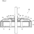
- a structure of the rotor 5B will be explained with reference to Fig. 2 .
- One end of the rotor shaft 3 is rotatably supported by the pair of bearing portions 9a and 9b (refer to Fig. 1 ).
- a rotor yoke 12 formed in a cup shape is integrally fitted to a cylindrical boss portion 12c formed to stand on a rotor hub 12b positioned in a center of a top surface portion 12a by press-fitting, shrink-fitting, bonding or the like.
- the rotor yoke 12 is arranged in the housing space 4 on an inner diameter side of the impeller 2 so as to overlap the impeller 2 in the axial direction (refer to Fig. 1 ). Accordingly, it is possible to reduce a size of the blower 1 by suppressing a height of assembly of the impeller 2 and the rotor yoke 12 in the axial direction that are coaxially fixed to the rotor shaft 3.
- a plurality of rotor magnets 13 divided in a segment state are provided on an inner peripheral side of an annually-formed side surface of the rotor yoke 12 (refer to Fig. 4 ).
- the rotor magnets 13 are arranged at given intervals by using any one of through holes 12d provided in the rotor yoke 12 as a reference.
- respective rotor magnets 13 are bonded and fixed to the inner peripheral surface of the rotor yoke 12 so as to face tip end surfaces (magnetic-flux action surfaces: refer to Fig. 1 ) of the stator pole teeth 10a of the stator core 11.
- the cylindrical boss portion 12c is formed to stand on the rotor hub 12b at the center of the top surface portion 12a in the rotor yoke 12.
- the rotor shaft 3 is integrally fitted to the boss portion 12c by press-fitting, shrink-fitting, bonding or the like.
- the top portion 12a is also provided with the plural through holes (piercing holes) 12d at equal intervals in the circumferential direction. These through holes 12d are provided for reducing weight of the rotor yoke 12.
- a disc-shaped reinforcing hub 14 and the rotor shaft 3 are integrally attached to an inner bottom portion 12b1 of the rotor hub 12b, which is concentrically fixed to the rotor hub 12b so as to overlap the rotor hub 12b.
- the reinforcing hub 14 is arranged so that a flange portion 14g formed on an outer peripheral edge portion of a side portion 14c surrounding a bottom portion 14b formed by drawing a metal plate such as SUS overlaps the rotor hub 12b.
- a cylindrical boss portion 14a formed by performing burring is formed to stand on the center of the bottom portion.
- the rotor shaft 3 is integrally fitted to a cylindrical hole of the boss portion 14a by press-fitting, shrink-fitting, bonding or the like (refer to Fig. 2 ).
- the strength in a fitted part between the rotor yoke 12 and the rotor shaft 3 is improved to thereby suppress the runout of the top surface, and a natural frequency of vibration in the motor is allowed to differ from a frequency of vibration generated by rotation of the impeller 2 (rotated body) to be a load to thereby prevent resonance and realize noise reduction.
- radial ribs 12e radial grooves 12g when seeing the top surface portion 12a from above: Fig. 3
- annular rib 12f an annular rib 12h when seeing the top surface portion 12a from above: Fig. 3
- the radial ribs 12e are formed so as to cross the annular rib 12f (annular groove 12h: Fig. 3 ).
- the reinforcing hub 14 is arranged so that the flange portion 14g (outer peripheral edge portion) overlaps the annular rib 12f concentrically formed in the rotor hub 12b on the inner bottom portion's side of the rotor yoke 12 formed in the cup shape.
- the rotor yoke 12 since the mechanical strength of the rotor hub 12b itself is improved and the strength of the rotor yoke 12 is further improved by the reinforcing hub 14 formed so as to overlap the rotor hub 12b, the rotor yoke 12 hardly vibrates and noise reduction can be improved.
- blower including an outer rotor type motor
- Fig. 6 to Fig. 10 The same numbers are added to the same components as the first embodiment, and explanation is cited.
- the plural radial ribs 12e (the radial grooves 12g when seeing the top surface portion 12a from above: Fig. 8 ) in the radial direction and the annular rib 12f (the annular groove 12h when seeing the top surface portion 12a from above: Fig. 7 ) that is concentric with the rotor shaft 3 are formed on the inner bottom portion of 12b1 of the rotor hub 12b in the same manner as the first embodiment.
- the reinforcing hub 14 is provided so that the flange portion 14g as an outer peripheral edge portion overlaps the annular groove 12h formed in the rotor hub 12b on the top surface 12a side of the rotor yoke 12.
- the reinforcing hub 14 is attached so that the flange portion 14g formed on the outer peripheral edge portion of a side portion 14f surrounding an inner bottom portion 14e formed by drawing a metal plate such as SUS overlaps the rotor hub 12b.
- a center hole 14d is drilled in the center of the inner bottom portion 14b.
- the rotor shaft 3 is integrally fitted to the center hole 14d by press-fitting, shrink-fitting, bonding or the like (refer to Fig. 7 ).
- the reinforcing hub 14 is arranged so that the flange portion 14g (outer peripheral edge portion) overlaps the annular groove 12h concentrically formed in the rotor hub 12b on the top surface 12a side of the rotor yoke 12 formed in the cup shape.
- the reinforcing hub 14 is housed in the housing space 4 of the impeller 2 and integrally fastened to the rotor shaft 3 while being attached to the top surface 12a of the rotor yoke 12 in the overlapped manner.
- the mechanical strength of the rotor hub 12b itself is improved and the strength of the rotor yoke 12 is further improved by the reinforcing hub 14 that overlaps the rotor hub 12b, therefore, the runout of the top surface of the rotor yoke 12 hardly occurs and noise reduction can be realized.
- the radial ribs 12e and the annular rib 12f formed in the rotor hub 12b of the rotor yoke 12 are preferably formed so as to be convex toward the inner bottom portion 12b1 side, it is also preferable that they are formed so as to be convex toward the top surface 12a side.
- the number of radial ribs 12e and the number of annular rib 12f are not limited to the state disclosed in the embodiments and may be larger as well as smaller.
- the shape of the reinforcing hub 14 is not limited to the disc shape, and may be other shapes such as a flower shape and a hook shape.
- the reinforcing hub 14 is arranged so as to overlap the inner bottom portion 12b1 of the rotor yoke 12 because generation of noise can be suppressed and the height of the rotor in the axial direction can be suppressed as compared with the case where the reinforcing hub 14 is arranged so as to overlap the top surface portion 12a.
Landscapes
- Engineering & Computer Science (AREA)
- Power Engineering (AREA)
- Mechanical Engineering (AREA)
- General Engineering & Computer Science (AREA)
- Iron Core Of Rotating Electric Machines (AREA)
- Permanent Field Magnets Of Synchronous Machinery (AREA)
- Structures Of Non-Positive Displacement Pumps (AREA)
- Motor Or Generator Frames (AREA)
Applications Claiming Priority (1)
| Application Number | Priority Date | Filing Date | Title |
|---|---|---|---|
| JP2017014501A JP6827331B2 (ja) | 2017-01-30 | 2017-01-30 | アウターロータ型モータ |
Publications (1)
| Publication Number | Publication Date |
|---|---|
| EP3355451A1 true EP3355451A1 (de) | 2018-08-01 |
Family
ID=60813663
Family Applications (1)
| Application Number | Title | Priority Date | Filing Date |
|---|---|---|---|
| EP17210621.3A Withdrawn EP3355451A1 (de) | 2017-01-30 | 2017-12-27 | Motor vom aussenrotortyp |
Country Status (4)
| Country | Link |
|---|---|
| US (1) | US10594186B2 (de) |
| EP (1) | EP3355451A1 (de) |
| JP (1) | JP6827331B2 (de) |
| CN (1) | CN108377046A (de) |
Cited By (5)
| Publication number | Priority date | Publication date | Assignee | Title |
|---|---|---|---|---|
| EP3611829A1 (de) * | 2018-08-17 | 2020-02-19 | Whirlpool Corporation | Lärmminderung eines rotors für eine waschmaschine |
| FR3111024A1 (fr) * | 2020-06-01 | 2021-12-03 | Valeo Systemes Thermiques | Rotor de moteur, notamment pour moteur de ventilateur d’installation de chauffage, ventilation et/ou climatisation de véhicule automobile |
| GB2608165A (en) * | 2021-06-24 | 2022-12-28 | Eta Green Power Ltd | Rotor for an electric machine |
| GB2608167A (en) * | 2021-06-24 | 2022-12-28 | Eta Green Power Ltd | Rotor for an electric machine |
| EP4123882A3 (de) * | 2021-06-24 | 2023-06-07 | ETA Green Power Ltd. | Rotor für eine elektrische maschine |
Families Citing this family (11)
| Publication number | Priority date | Publication date | Assignee | Title |
|---|---|---|---|---|
| JP6856446B2 (ja) * | 2017-05-23 | 2021-04-07 | 澤藤電機株式会社 | アウターロータ型電動機におけるロータ構造 |
| FR3069586B1 (fr) * | 2017-07-26 | 2021-01-01 | Valeo Systemes Thermiques | Pulseur d'air pour vehicule automobile |
| CN216016679U (zh) * | 2019-02-22 | 2022-03-11 | 日本电产株式会社 | 马达以及送风装置 |
| KR102258295B1 (ko) * | 2019-11-14 | 2021-06-01 | 주식회사 삼현 | 하이브리드 드론용 발전기 |
| TWI725683B (zh) * | 2019-12-24 | 2021-04-21 | 建準電機工業股份有限公司 | 扇輪及具有該扇輪之散熱風扇 |
| DE102020215183A1 (de) * | 2020-12-02 | 2022-06-02 | BSH Hausgeräte GmbH | Rotor mit integriertem Lüfter, Elektromotor, Pumpenvorrichtung, Haushaltsgerät und Herstellungsverfahren |
| KR102286878B1 (ko) * | 2021-02-10 | 2021-08-09 | 이만홍 | 구동 제어 기능이 개선된 ec 모터 |
| US11909268B2 (en) | 2021-03-11 | 2024-02-20 | ZF Active Safety US Inc. | Integrated rotor |
| DE102021204575A1 (de) * | 2021-05-06 | 2022-11-10 | Zf Friedrichshafen Ag | Rotoranordnung für eine elektrische Maschine |
| KR102587281B1 (ko) * | 2021-07-07 | 2023-10-10 | 김태헌 | 외전형 bldc 전동기용 회전자 및 이를 구비하는 외전형 bldc 전동기 |
| US20250070619A1 (en) * | 2023-08-22 | 2025-02-27 | Milwaukee Electric Tool Corporation | Power tool including a motor with blower fan blades |
Citations (10)
| Publication number | Priority date | Publication date | Assignee | Title |
|---|---|---|---|---|
| US3691542A (en) * | 1970-11-02 | 1972-09-12 | Diablo Systems Inc | Magnetic memory disk drive apparatus with reduced r. f. noise |
| JPH07332291A (ja) * | 1994-06-10 | 1995-12-22 | Hitachi Ltd | 空調機用ファン取付構造 |
| US20060039058A1 (en) * | 2004-08-20 | 2006-02-23 | Shigeyoshi Mori | Polygon mirror drive motor |
| US7428087B1 (en) * | 2007-12-04 | 2008-09-23 | Sunonwealth Electric Machine Industry Co., Ltd. | Mirror structure for laser printer |
| US20130328432A1 (en) * | 2012-06-06 | 2013-12-12 | Nidec Motor Corporation | Motor having spoked outer rotor with spaced apart pole segments |
| US20140102152A1 (en) * | 2005-11-30 | 2014-04-17 | Hyeok Deok Kim | Washing machine |
| JP2015001202A (ja) | 2013-06-17 | 2015-01-05 | ミネベア株式会社 | 送風ファン |
| CN204118974U (zh) * | 2014-10-11 | 2015-01-21 | 上海电科电机科技有限公司 | 变频电机用标准轴套型增量编码器的安装结构 |
| JP2016086558A (ja) * | 2014-10-27 | 2016-05-19 | ミネベア株式会社 | スピンドルモータ |
| US20160218581A1 (en) * | 2010-06-25 | 2016-07-28 | Fisher & Paykel Appliances Limited | Rotor for a motor, and a motor and an appliance comprising the rotor, and a method for making a rotor |
Family Cites Families (10)
| Publication number | Priority date | Publication date | Assignee | Title |
|---|---|---|---|---|
| US4318017A (en) | 1980-01-04 | 1982-03-02 | Timex Corporation | Rotor assembly for electric stepping motor |
| JP2500696B2 (ja) * | 1990-02-02 | 1996-05-29 | ダイキン工業株式会社 | ファン装置 |
| JPH06189488A (ja) * | 1992-12-16 | 1994-07-08 | Toshiba Corp | 回転電機用ブラケット |
| ES2301228T3 (es) * | 1999-01-08 | 2008-06-16 | Lg Electronics Inc. | Estructura de rotor para un motor sin escobillas de tipo con rotor externo. |
| JP2002315245A (ja) * | 2001-04-09 | 2002-10-25 | Moric Co Ltd | 永久磁石式発電機のロータ |
| JP4325289B2 (ja) * | 2003-06-12 | 2009-09-02 | 国産電機株式会社 | 磁石発電機の回転子 |
| JPWO2005121575A1 (ja) | 2004-06-11 | 2008-04-10 | セイコーインスツル株式会社 | 流体動圧軸受、モータおよび記録媒体駆動装置 |
| DE102008008965A1 (de) | 2008-02-13 | 2009-08-20 | Continental Automotive Gmbh | Elektromotor |
| ITTO20111159A1 (it) * | 2011-12-15 | 2013-06-16 | Gate Srl | Motore elettrico per l'azionamento di una girante di un ventilatore per uno scambiatore di calore di un autoveicolo. |
| MY182248A (en) * | 2015-06-08 | 2021-01-18 | Panasonic Ip Man Co Ltd | Brushless dc motor and blower device |
-
2017
- 2017-01-30 JP JP2017014501A patent/JP6827331B2/ja not_active Expired - Fee Related
- 2017-12-27 EP EP17210621.3A patent/EP3355451A1/de not_active Withdrawn
-
2018
- 2018-01-05 US US15/862,718 patent/US10594186B2/en active Active
- 2018-01-24 CN CN201810068474.8A patent/CN108377046A/zh active Pending
Patent Citations (10)
| Publication number | Priority date | Publication date | Assignee | Title |
|---|---|---|---|---|
| US3691542A (en) * | 1970-11-02 | 1972-09-12 | Diablo Systems Inc | Magnetic memory disk drive apparatus with reduced r. f. noise |
| JPH07332291A (ja) * | 1994-06-10 | 1995-12-22 | Hitachi Ltd | 空調機用ファン取付構造 |
| US20060039058A1 (en) * | 2004-08-20 | 2006-02-23 | Shigeyoshi Mori | Polygon mirror drive motor |
| US20140102152A1 (en) * | 2005-11-30 | 2014-04-17 | Hyeok Deok Kim | Washing machine |
| US7428087B1 (en) * | 2007-12-04 | 2008-09-23 | Sunonwealth Electric Machine Industry Co., Ltd. | Mirror structure for laser printer |
| US20160218581A1 (en) * | 2010-06-25 | 2016-07-28 | Fisher & Paykel Appliances Limited | Rotor for a motor, and a motor and an appliance comprising the rotor, and a method for making a rotor |
| US20130328432A1 (en) * | 2012-06-06 | 2013-12-12 | Nidec Motor Corporation | Motor having spoked outer rotor with spaced apart pole segments |
| JP2015001202A (ja) | 2013-06-17 | 2015-01-05 | ミネベア株式会社 | 送風ファン |
| CN204118974U (zh) * | 2014-10-11 | 2015-01-21 | 上海电科电机科技有限公司 | 变频电机用标准轴套型增量编码器的安装结构 |
| JP2016086558A (ja) * | 2014-10-27 | 2016-05-19 | ミネベア株式会社 | スピンドルモータ |
Cited By (10)
| Publication number | Priority date | Publication date | Assignee | Title |
|---|---|---|---|---|
| EP3611829A1 (de) * | 2018-08-17 | 2020-02-19 | Whirlpool Corporation | Lärmminderung eines rotors für eine waschmaschine |
| US11456638B2 (en) | 2018-08-17 | 2022-09-27 | Whirlpool Corporation | Acoustical treatment for a rotor of a laundry appliance |
| FR3111024A1 (fr) * | 2020-06-01 | 2021-12-03 | Valeo Systemes Thermiques | Rotor de moteur, notamment pour moteur de ventilateur d’installation de chauffage, ventilation et/ou climatisation de véhicule automobile |
| WO2021245079A1 (fr) * | 2020-06-01 | 2021-12-09 | Valeo Systemes Thermiques | Rotor de moteur, notamment pour moteur de ventilateur d'installation de chauffage, ventilation et/ou climatisation de vehicule automobile |
| GB2608165A (en) * | 2021-06-24 | 2022-12-28 | Eta Green Power Ltd | Rotor for an electric machine |
| GB2608167A (en) * | 2021-06-24 | 2022-12-28 | Eta Green Power Ltd | Rotor for an electric machine |
| EP4123882A3 (de) * | 2021-06-24 | 2023-06-07 | ETA Green Power Ltd. | Rotor für eine elektrische maschine |
| GB2608167B (en) * | 2021-06-24 | 2023-11-22 | Eta Green Power Ltd | Rotor for an electric machine |
| GB2608165B (en) * | 2021-06-24 | 2024-04-24 | Eta Green Power Ltd | Rotor for an electric machine |
| US12308705B2 (en) | 2021-06-24 | 2025-05-20 | Eta Green Power Limited | Rotor for an electric machine |
Also Published As
| Publication number | Publication date |
|---|---|
| CN108377046A (zh) | 2018-08-07 |
| JP2018125920A (ja) | 2018-08-09 |
| US10594186B2 (en) | 2020-03-17 |
| JP6827331B2 (ja) | 2021-02-10 |
| US20180219446A1 (en) | 2018-08-02 |
Similar Documents
| Publication | Publication Date | Title |
|---|---|---|
| US10594186B2 (en) | Outer rotor type motor | |
| US8568110B2 (en) | Blower fan and method of manufacturing the same | |
| US8137079B2 (en) | Motor, fan and manufacturing method of the same | |
| US8113793B2 (en) | Fan | |
| US20130052049A1 (en) | Centrifugal fan | |
| JP2008245427A (ja) | モータ | |
| JP2012087748A (ja) | 送風ファン | |
| JP2014113030A (ja) | モータ | |
| JP2012097655A (ja) | 送風ファン | |
| JP2016011627A (ja) | 遠心式ファン | |
| WO2011158471A1 (ja) | ファンモータ、このファンモータを用いた車載用空調装置およびファンモータの組立方法 | |
| CN104712574A (zh) | 轴流风扇和串联型轴流风扇 | |
| JP2001186741A (ja) | 送風機 | |
| JP3809438B2 (ja) | 遠心ブロワ | |
| JP7179609B2 (ja) | 軸流ファン | |
| US20120003109A1 (en) | Blower fan | |
| JP2021515520A (ja) | 電気モータ | |
| JP2020153275A (ja) | 遠心ファン | |
| JP2014015908A (ja) | ブロワユニット | |
| US11901798B2 (en) | Fan motor | |
| US20230023583A1 (en) | External rotor cup for a fan motor of a motor vehicle | |
| JP5095329B2 (ja) | モータおよび送風ファン | |
| JP2007507193A (ja) | モーター | |
| WO2019064881A1 (ja) | 軸流ファン | |
| JP7179608B2 (ja) | 軸流ファン |
Legal Events
| Date | Code | Title | Description |
|---|---|---|---|
| PUAI | Public reference made under article 153(3) epc to a published international application that has entered the european phase |
Free format text: ORIGINAL CODE: 0009012 |
|
| STAA | Information on the status of an ep patent application or granted ep patent |
Free format text: STATUS: THE APPLICATION HAS BEEN PUBLISHED |
|
| AK | Designated contracting states |
Kind code of ref document: A1 Designated state(s): AL AT BE BG CH CY CZ DE DK EE ES FI FR GB GR HR HU IE IS IT LI LT LU LV MC MK MT NL NO PL PT RO RS SE SI SK SM TR |
|
| AX | Request for extension of the european patent |
Extension state: BA ME |
|
| STAA | Information on the status of an ep patent application or granted ep patent |
Free format text: STATUS: REQUEST FOR EXAMINATION WAS MADE |
|
| 17P | Request for examination filed |
Effective date: 20190129 |
|
| RBV | Designated contracting states (corrected) |
Designated state(s): AL AT BE BG CH CY CZ DE DK EE ES FI FR GB GR HR HU IE IS IT LI LT LU LV MC MK MT NL NO PL PT RO RS SE SI SK SM TR |
|
| STAA | Information on the status of an ep patent application or granted ep patent |
Free format text: STATUS: EXAMINATION IS IN PROGRESS |
|
| 17Q | First examination report despatched |
Effective date: 20190318 |
|
| STAA | Information on the status of an ep patent application or granted ep patent |
Free format text: STATUS: THE APPLICATION IS DEEMED TO BE WITHDRAWN |
|
| 18D | Application deemed to be withdrawn |
Effective date: 20200917 |