EP3354875B1 - Aussenbordmotor - Google Patents
Aussenbordmotor Download PDFInfo
- Publication number
- EP3354875B1 EP3354875B1 EP17203757.4A EP17203757A EP3354875B1 EP 3354875 B1 EP3354875 B1 EP 3354875B1 EP 17203757 A EP17203757 A EP 17203757A EP 3354875 B1 EP3354875 B1 EP 3354875B1
- Authority
- EP
- European Patent Office
- Prior art keywords
- combustion chamber
- upward
- pair
- outboard motor
- spark plug
- Prior art date
- Legal status (The legal status is an assumption and is not a legal conclusion. Google has not performed a legal analysis and makes no representation as to the accuracy of the status listed.)
- Active
Links
Images



Classifications
-
- B—PERFORMING OPERATIONS; TRANSPORTING
- B63—SHIPS OR OTHER WATERBORNE VESSELS; RELATED EQUIPMENT
- B63H—MARINE PROPULSION OR STEERING
- B63H20/00—Outboard propulsion units, e.g. outboard motors or Z-drives; Arrangements thereof on vessels
- B63H20/24—Arrangements, apparatus and methods for handling exhaust gas in outboard drives, e.g. exhaust gas outlets
-
- B—PERFORMING OPERATIONS; TRANSPORTING
- B63—SHIPS OR OTHER WATERBORNE VESSELS; RELATED EQUIPMENT
- B63H—MARINE PROPULSION OR STEERING
- B63H20/00—Outboard propulsion units, e.g. outboard motors or Z-drives; Arrangements thereof on vessels
- B63H20/28—Arrangements, apparatus and methods for handling cooling-water in outboard drives, e.g. cooling-water intakes
-
- F—MECHANICAL ENGINEERING; LIGHTING; HEATING; WEAPONS; BLASTING
- F01—MACHINES OR ENGINES IN GENERAL; ENGINE PLANTS IN GENERAL; STEAM ENGINES
- F01P—COOLING OF MACHINES OR ENGINES IN GENERAL; COOLING OF INTERNAL-COMBUSTION ENGINES
- F01P3/00—Liquid cooling
- F01P3/02—Arrangements for cooling cylinders or cylinder heads
-
- F—MECHANICAL ENGINEERING; LIGHTING; HEATING; WEAPONS; BLASTING
- F01—MACHINES OR ENGINES IN GENERAL; ENGINE PLANTS IN GENERAL; STEAM ENGINES
- F01P—COOLING OF MACHINES OR ENGINES IN GENERAL; COOLING OF INTERNAL-COMBUSTION ENGINES
- F01P3/00—Liquid cooling
- F01P3/12—Arrangements for cooling other engine or machine parts
- F01P3/16—Arrangements for cooling other engine or machine parts for cooling fuel injectors or sparking-plugs
-
- F—MECHANICAL ENGINEERING; LIGHTING; HEATING; WEAPONS; BLASTING
- F01—MACHINES OR ENGINES IN GENERAL; ENGINE PLANTS IN GENERAL; STEAM ENGINES
- F01P—COOLING OF MACHINES OR ENGINES IN GENERAL; COOLING OF INTERNAL-COMBUSTION ENGINES
- F01P3/00—Liquid cooling
- F01P3/20—Cooling circuits not specific to a single part of engine or machine
- F01P3/202—Cooling circuits not specific to a single part of engine or machine for outboard marine engines
-
- F—MECHANICAL ENGINEERING; LIGHTING; HEATING; WEAPONS; BLASTING
- F02—COMBUSTION ENGINES; HOT-GAS OR COMBUSTION-PRODUCT ENGINE PLANTS
- F02F—CYLINDERS, PISTONS OR CASINGS, FOR COMBUSTION ENGINES; ARRANGEMENTS OF SEALINGS IN COMBUSTION ENGINES
- F02F1/00—Cylinders; Cylinder heads
- F02F1/24—Cylinder heads
- F02F1/26—Cylinder heads having cooling means
- F02F1/36—Cylinder heads having cooling means for liquid cooling
- F02F1/38—Cylinder heads having cooling means for liquid cooling the cylinder heads being of overhead valve type
-
- B—PERFORMING OPERATIONS; TRANSPORTING
- B63—SHIPS OR OTHER WATERBORNE VESSELS; RELATED EQUIPMENT
- B63H—MARINE PROPULSION OR STEERING
- B63H20/00—Outboard propulsion units, e.g. outboard motors or Z-drives; Arrangements thereof on vessels
- B63H20/001—Arrangements, apparatus and methods for handling fluids used in outboard drives
-
- F—MECHANICAL ENGINEERING; LIGHTING; HEATING; WEAPONS; BLASTING
- F01—MACHINES OR ENGINES IN GENERAL; ENGINE PLANTS IN GENERAL; STEAM ENGINES
- F01P—COOLING OF MACHINES OR ENGINES IN GENERAL; COOLING OF INTERNAL-COMBUSTION ENGINES
- F01P3/00—Liquid cooling
- F01P3/02—Arrangements for cooling cylinders or cylinder heads
- F01P2003/024—Cooling cylinder heads
-
- F—MECHANICAL ENGINEERING; LIGHTING; HEATING; WEAPONS; BLASTING
- F02—COMBUSTION ENGINES; HOT-GAS OR COMBUSTION-PRODUCT ENGINE PLANTS
- F02B—INTERNAL-COMBUSTION PISTON ENGINES; COMBUSTION ENGINES IN GENERAL
- F02B61/00—Adaptations of engines for driving vehicles or for driving propellers; Combinations of engines with gearing
- F02B61/04—Adaptations of engines for driving vehicles or for driving propellers; Combinations of engines with gearing for driving propellers
- F02B61/045—Adaptations of engines for driving vehicles or for driving propellers; Combinations of engines with gearing for driving propellers for marine engines
-
- F—MECHANICAL ENGINEERING; LIGHTING; HEATING; WEAPONS; BLASTING
- F02—COMBUSTION ENGINES; HOT-GAS OR COMBUSTION-PRODUCT ENGINE PLANTS
- F02B—INTERNAL-COMBUSTION PISTON ENGINES; COMBUSTION ENGINES IN GENERAL
- F02B75/00—Other engines
- F02B75/16—Engines characterised by number of cylinders, e.g. single-cylinder engines
- F02B75/18—Multi-cylinder engines
- F02B75/22—Multi-cylinder engines with cylinders in V, fan, or star arrangement
-
- F—MECHANICAL ENGINEERING; LIGHTING; HEATING; WEAPONS; BLASTING
- F02—COMBUSTION ENGINES; HOT-GAS OR COMBUSTION-PRODUCT ENGINE PLANTS
- F02F—CYLINDERS, PISTONS OR CASINGS, FOR COMBUSTION ENGINES; ARRANGEMENTS OF SEALINGS IN COMBUSTION ENGINES
- F02F1/00—Cylinders; Cylinder heads
- F02F1/24—Cylinder heads
- F02F1/242—Arrangement of spark plugs or injectors
Definitions
- the present invention relates to an outboard motor, and more particularly, it relates to an outboard motor including an internal combustion engine including a fuel injector configured to inject fuel into a combustion chamber.
- An internal combustion engine as a direct-injection engine that directly supplies liquid fuel to a combustion chamber to increase its output and fuel economy is known in general.
- Such an internal combustion engine is disclosed in JP 2012-241698 A (family member: EP 2 527 639 A1 ), for example.
- JP 2012-241698 A (family member: EP 2 527 639 A1 ) discloses a four-cycle engine (internal combustion engine) housed in a cowling of a marine vessel propulsion device and including a cylinder head including an intake opening through which intake air is introduced into a combustion chamber and an exhaust opening through which exhaust gas is discharged from the combustion chamber.
- a fuel injector that injects fuel into the combustion chamber and a spark plug that provides ignition within the combustion chamber by generating a spark in the combustion chamber are mounted in the cylinder head of the four-cycle engine disclosed in JP 2012-241698 A (family member: EP 2 527 639 A1 ).
- the spark plug is mounted in the cylinder head so as to extend along an axial direction in which a cylinder of the four-stroke engine extends.
- the tip of the spark plug is disposed at the center of the combustion chamber between the intake opening and the exhaust opening.
- the fuel injector is mounted in the cylinder head at an angle with respect to the axial direction in which the cylinder extends.
- the tip of the fuel injector is spaced apart from the axis (the center of the combustion chamber) beyond the intake opening in the combustion chamber, and the fuel injector is disposed below an intake valve that opens and closes the intake opening.
- a fuel injector In a direct-injection engine, it is necessary to homogenously mix injected fuel and air in a combustion chamber and burn the mixture at a high speed in order to increase the combustion efficiency. Therefore, it is necessary to dispose a fuel injector at a position at which fuel and air are uniformly mixed, such as on a bore centerline that passes through the combustion chamber, an intake opening, and an exhaust opening, and cause the fuel injector to inject fuel in an appropriate direction.
- a spark plug near the center of the combustion chamber to create a flame front on a substantially concentric circle from the center of the combustion chamber, two-point ignition provided by disposing a plurality of spark plugs in the combustion chamber, etc.
- the fuel injector is disposed below the intake valve, and hence the fuel injector is likely to interfere with another member that the outboard motor includes.
- the four-cycle engine disclosed in JP 2012-241698 A family member: EP 2 527 639 A1
- the four-cycle engine disclosed in JP 2012-241698 A family member: EP 2 527 639 A1
- the four-cycle engine disclosed in JP 2012-241698 A family member: EP 2 527 639 A1
- the four-cycle engine disclosed in JP 2012-241698 A family member: EP 2 527 639 A1
- the width of the entire outboard motor is increased, and hence the size of the outboard motor is increased.
- the outboard motors are likely to interfere with each other such that it is difficult to dispose the plurality of outboard motors in the width direction.
- the spark plug is also disposed near the center of the combustion chamber, and hence the fuel injector and the spark plug interfere with each other, and a valve actuator that transmits a drive force to a valve is also likely to interfere with the fuel injector and the spark plug. Therefore, in an internal combustion engine of an outboard motor, it is desired to dispose a fuel injector and an ignition such that a favorable flame front is created while an air-fuel mixture distribution is homogenized in a state where constraints on the shape and layout of a valve actuator are reduced.
- an outboard motor having the features of the independent claim 1. Preferred embodiments are laid down in the dependent claims.
- An outboard motor includes an internal combustion engine, a cowling in which the internal combustion engine is housed, and a propulsion unit configured to convert a rotational drive force of the internal combustion engine into a thrust force.
- the internal combustion engine includes a cylinder head including an intake opening through which intake air is introduced into a combustion chamber of a cylinder and an exhaust opening through which exhaust gas is discharged from the combustion chamber, a plurality of valves configured to open and close the intake opening and the exhaust opening, a pair of valve actuators provided in correspondence to the cylinder head, each including a camshaft and configured to transmit a drive force to the plurality of valves, a fuel injector including a fuel injection portion configured to inject fuel from a central region of the combustion chamber between the intake opening and the exhaust opening into the combustion chamber, the fuel injector mounted in the cylinder head, and a spark plug including an ignition portion located to be offset in the direction of the camshaft with respect to the fuel injection portion in said central region and configured to provide ignition within the combustion chamber, the spark plug mounted
- the fuel injection portion and the ignition portion configured to provide ignition within the combustion chamber are disposed in the central region of the combustion chamber between the intake opening and the exhaust opening.
- the injection of fuel is performed in the central region of the combustion chamber, and hence liquid fuel is appropriately injected such that the fuel is evenly distributed in the combustion chamber. Consequently, the distribution of an air-fuel mixture produced by mixing the fuel and the intake air is homogenized in the combustion chamber.
- the air-fuel mixture homogenized in the combustion chamber is ignited in the central region of the combustion chamber.
- the fuel injector and the spark plug are disposed such that a favorable flame front is created while the air-fuel mixture distribution is homogenized, and hence the combustion efficiency of the internal combustion engine is improved.
- the ignition portion is deviated in the upward-downward direction in which the camshaft extends with respect to the fuel injection portion in the central region of the combustion chamber between the intake opening and the exhaust opening.
- the ignition portion and the fuel injection portion are aligned in a direction perpendicular to the upward-downward direction in which the camshaft extends, it is necessary to largely ensure a distance between the intake opening and the exhaust opening in order to significantly reduce or prevent interference of the spark plug and the fuel injector with components mounted in the cylinder head such as the valve actuators.
- the distance between the intake opening and the exhaust opening increases, and hence an angle (setting angle) between the valve configured to open and close the intake opening and the valve configured to open and close the exhaust opening increases.
- the size of the internal combustion engine increases in the direction perpendicular to the upward-down direction in which the camshaft extends.
- the ignition portion is deviated in the upward-downward direction in which the camshaft extends with respect to the fuel injection portion in the central region of the combustion chamber between the intake opening and the exhaust opening.
- the outboard motor including the internal combustion engine in which the fuel injector and the spark plug are disposed such that a favorable flame front is created while the air-fuel mixture distribution is homogenized in a state where constraints on the shape and layout of the valve actuators are reduced is provided.
- At least one of the fuel injector and the spark plug is preferably inclined with respect to a first direction in which the cylinder of the internal combustion engine extends along the upward-downward direction between the pair of valve actuators in the cylinder head. Accordingly, at least one of the fuel injector and the spark plug escapes in the upward-downward direction in which the camshaft extends, and hence as compared with the case where neither the fuel injector nor the spark plug is inclined, the fuel injector and the spark plug are easily spaced apart from each other while interference of the fuel injector and the spark plug with the valve actuators is significantly reduced or prevented. Consequently, the fuel injector and the spark plug are easily mounted in the cylinder head so as not to interfere with each other in a state where constraints on the shape and layout of the valve actuators are reduced.
- the spark plug is preferably inclined away from the fuel injector along the upward-downward direction between the pair of valve actuators in the cylinder head. Accordingly, the fuel injector and the spark plug inclined away from the fuel injector are more easily mounted in the cylinder head so as not to interfere with each other in a state where constraints on the shape and layout of the valve actuators are reduced.
- the ignition portion is preferably deviated in the upward-downward direction from a center of the combustion chamber in the upward-downward direction. Accordingly, the ignition portion is deviated in the upward-downward direction from the center of the combustion chamber in the upward-downward direction, and hence the fuel injection portion is easily disposed near the center of the combustion chamber in the upward-downward direction. Consequently, the fuel injection portion is disposed such that the air-fuel mixture is more homogeneously distributed from the vicinity of the center of the combustion chamber in the upward-downward direction to the entirety of the combustion chamber.
- the fuel injection portion is preferably deviated in a second direction perpendicular to the upward-downward direction from a center of the combustion chamber in the second direction on a centerline that passes through the center of the combustion chamber in the upward-downward direction and extends in the second direction or near the centerline. Accordingly, the fuel injection portion is deviated in the second direction from the center of the combustion chamber in the second direction, and hence the ignition portion deviated in the upward-downward direction from the center in the upward-downward direction is easily disposed near the center of the combustion chamber in the second direction.
- the fuel injection portion is disposed such that the air-fuel mixture is more homogeneously distributed from the vicinity of the center of the combustion chamber in the upward-downward direction to the entirety of the combustion chamber, and the ignition portion is disposed such that the combustion more uniformly propagates from the vicinity of the center of the combustion chamber in the second direction. Therefore, the combustion efficiency of the internal combustion engine is further improved.
- the intake opening and the exhaust opening are preferably respectively provided on one side and the other side in the second direction with respect to the center of the combustion chamber in the second direction, and the fuel injection portion is preferably deviated to the one side in the second direction with respect to the center of the combustion chamber in the second direction. Accordingly, the fuel injection portion is disposed away from the vicinity of the exhaust opening, the temperature of which is likely to be high, and hence occurrence of a thermal failure in the fuel injector is significantly reduced or prevented.
- the fuel injector preferably extends in a first direction in which the cylinder of the internal combustion engine extends between the pair of valve actuators in the cylinder head. Accordingly, interference of the fuel injector with the pair of valve actuators etc. is further significantly reduced or prevented. Furthermore, the position of the fuel injection portion such as the injection angle of the fuel injection portion is easily adjusted such that the air-fuel mixture becomes homogeneous throughout the combustion chamber.
- the internal combustion engine preferably further includes a valve actuator lid unit configured to cover the pair of valve actuators
- the fuel injector is preferably inclined with respect to a first direction in which the cylinder of the internal combustion engine extends along a second direction perpendicular to the upward-downward direction in a state where the fuel injector avoids the pair of valve actuators and the valve actuator lid unit between the pair of valve actuators in the cylinder head. Accordingly, an increase in the length of the fuel injector in the first direction in which the cylinder extends is significantly reduced or prevented while interference of the fuel injector with the pair of valve actuators and the valve actuator lid unit is significantly reduced or prevented.
- the spark plug preferably includes a first spark plug including a first ignition portion deviated to one side in the upward-downward direction with respect to the fuel injection portion in the central region and configured to provide spark plug within the combustion chamber, the first spark plug inclined away from the fuel injector toward the one side in the upward-downward direction between the pair of valve actuators in the cylinder head, and a second spark plug including a second ignition portion deviated to the other side in the upward-downward direction with respect to the fuel injection portion in the central region and configured to provide ignition within the combustion chamber, the second spark plug inclined away from the fuel injector toward the other side in the upward-downward direction between the pair of valve actuators in the cylinder head.
- the fuel injector and the plurality of spark plugs are easily mounted in the cylinder head so as not to interfere with each other. Furthermore, the plurality of spark plugs is provided such that the combustion in the combustion chamber more uniformly propagates due to two-point ignition.
- the intake opening preferably includes a pair of intake openings provided on one side in a second direction perpendicular to the upward-downward direction with respect to a center of the combustion chamber in the second direction
- the exhaust opening preferably includes a pair of exhaust openings provided on the other side in the second direction with respect to the center of the combustion chamber in the second direction
- the central region of the combustion chamber is preferably provided in a region surrounded by the pair of intake openings and the pair of exhaust openings. Accordingly, the fuel injection portion and the ignition portion are disposed in the central region surrounded by the pair of intake openings and the pair of exhaust openings such that the combustion efficiency of the multi-valve internal combustion engine is further improved.
- the fuel injection portion preferably injects the fuel into the combustion chamber from between the pair of intake openings provided on the one side in the second direction with respect to the center of the combustion chamber in the second direction or from between the pair of exhaust openings provided on the other side in the second direction with respect to the center of the combustion chamber in the second direction
- the ignition portion is preferably disposed between the intake opening and the exhaust opening provided on one side in the upward-downward direction with respect to a center of the combustion chamber in the upward-downward direction.
- the fuel injection portion is disposed such that the air-fuel mixture is more homogeneously distributed from the vicinity of the center of the combustion chamber in the upward-downward direction to the entirety of the combustion chamber, and the ignition portion is disposed such that the combustion more uniformly propagates from the vicinity of the center of the combustion chamber in the second direction. Consequently, the combustion efficiency of the multi-valve internal combustion engine is further improved.
- the fuel injection portion injects the fuel from between the pair of intake openings or from between the pair of exhaust openings
- the fuel injection portion preferably injects the fuel into the combustion chamber from between the pair of intake openings provided on the one side in the second direction with respect to the center of the combustion chamber in the second direction. Accordingly, in the multi-valve internal combustion engine, the fuel injection portion is disposed away from the vicinity of the exhaust openings, the temperature of which is likely to be high, and hence occurrence of a thermal failure in the fuel injector is significantly reduced or prevented.
- valve actuators are preferably direct-acting valve actuators including a plurality of cams configured to come into contact with cam contacts of the plurality of valves, respectively. Accordingly, it is not necessary to provide rocker arms, a mechanism that drives the rocker arms, etc. in the valve actuators as compared with the case where the valve actuators are rocker arm-type valve actuators including rocker arms that transmit a drive force between the valve actuators and valves. Consequently, the number of components of the internal combustion engine is reduced, and an increase in the size of the internal combustion engine is significantly reduced or prevented.
- the direct-acting valve actuators are preferably used.
- the internal combustion engine is preferably a V-type internal combustion engine. Accordingly, in the case of a V-type internal combustion engine, the fuel injection portion of the fuel injector and the ignition portion configured to provide ignition within the combustion chamber are disposed in the central region of the combustion chamber such that the combustion efficiency of the V-type internal combustion engine is further improved. Furthermore, when the internal combustion engine includes a plurality of cylinders, an increase in the size of the internal combustion engine in a direction in which the cylinders are aligned is significantly reduced or prevented as compared with an in-line internal combustion engine.
- the internal combustion engine is preferably housed in the cowling in a state where a plurality of the cylinders is aligned in the upward-downward direction. Accordingly, at least one of the fuel injector and the spark plug is inclined along the direction in which the plurality of cylinders disposed at intervals and likely to have empty spaces therebetween is aligned, and hence interference of at least one of the fuel injector and the spark plug with another component in the outboard motor is significantly reduced or prevented.
- a direction X represents the forward and rearward movement direction of a marine vessel 100a
- a direction Y represents a right-left direction perpendicular to the forward and rearward movement direction of the marine vessel 100a in a horizontal plane
- a direction Z represents an upward-downward direction perpendicular to the direction X and the direction Y (horizontal plane).
- the outboard motor 100 mounted on a vessel body 100b in a tilted-down state and in a state where no steering is performed (a state where a thrust force acts forward or rearward) is described.
- the outboard motor 100 is mounted on the vessel body 100b of the marine vessel 100a through a bracket 4.
- the outboard motor 100 includes a V-type six-cylinder engine 1, a propulsion unit 2, a cowling 3a in which the engine 1 is housed, and the bracket 4 that mounts the outboard motor 100 on the vessel body 100b.
- the engine 1 is an example of an "internal combustion engine”.
- the propulsion unit 2 converts the rotational drive force of the engine 1 into the thrust force of the marine vessel 100a.
- the propulsion unit 2 includes a drive shaft 2a connected to the engine 1, a propeller 2b, a propeller shaft 2c connected to the drive shaft 2a and the propeller 2b, and a switcher 2d that switches the direction of the thrust force by switching the rotational direction of the propeller 2b.
- the cowling 3a covers the engine 1 from above (direction Z1).
- a case 3b in which the drive shaft 2a and the switcher 2d of the propulsion unit 2, etc. are housed is disposed below the cowling 3a.
- the bracket 4 has a tilt (trim) function of rotating the outboard motor 100 about an axis that extends in the right-left direction (direction Y) and a steering function of performing steering by rotating the outboard motor 100 about an axis that extends in the upward-downward direction (direction Z).
- the outboard motor 100 further includes intakes 5 and exhausts 6.
- the intakes 5 supply air taken into the cowling 3a to the engine 1 as intake air.
- the exhausts 6 discharge exhaust gas discharged from the engine 1 into water outside the outboard motor 100 through an exhaust passage (not shown) provided in the outboard motor 100.
- ends of intake pipes 5a and exhaust pipes 6a are connected to six cylinders (cylinders 10a) of the engine 1, respectively.
- the engine 1 is a V-type six-cylinder four-cycle engine. That is, as shown in Fig. 2 , the cylinders 10a are disposed in a V-shape that opens rearward (direction X2) in a plan view from above (direction Z1).
- the engine 1 includes a pair of cylinder blocks 10 each including three cylinders 10a and a crankcase 11 on which the pair of cylinder blocks 10 is mounted in a V-shape and in which a crankshaft 11a is disposed.
- each of the pair of cylinder blocks 10 the three cylinders 10a are aligned in the upward-downward direction.
- pistons 10b are slidably disposed along a direction A in which the cylinders 10a extend.
- the direction A in which the cylinders 10 extend.
- the direction A in which the cylinders 10a provided in the cylinder block 10 on a Y1 side extend is different from the direction A in which the cylinders 10a provided in the cylinder block 10 on a Y2 side extend.
- the pistons 10b are mounted on the crankshaft 11 (see Fig. 1 ) through connecting rods 10c. Consequently, in the engine 1, the sliding of the pistons 10b in the direction A is converted into the rotation of the crankshaft 11a.
- the direction A is an example of a "first direction”.
- crankshaft 11a extends in the upward-downward direction (direction Z) inside the crankcase 11.
- direction Z the crankshaft 11a
- the lower end (Z2-side end) of the crankshaft 11a is connected to the drive shaft 2a.
- the rotation of the crankshaft 11a is transmitted to the drive shaft 2a such that the rotational drive force of the engine 1 is transmitted to the propeller 2b.
- a timing belt 12 is connected to the upper end (Z1-side end) of the crankshaft 11a.
- the timing belt 12 is disposed above (direction Z1) the cylinder blocks 10, the crankcase 11, and cylinder heads 20 described later, and extends in the horizontal plane.
- the timing belt 12 transmits the rotational drive force of the crankshaft 11a to camshafts 32 of valve actuators 31 described later.
- the engine 1 further includes a pair of cylinder heads 20 mounted on the pair of cylinder blocks 10, respectively, a pair of valve actuating units 30 that corresponds to the pair of cylinder heads 20, respectively, and a pair of valve actuator lid units 40 configured to cover the valve actuators 31 of the valve actuating units 30.
- the cylinder heads 20 each include three recesses 21 aligned in the upward-downward direction (direction perpendicular to the plane of the figure).
- the three recesses 21 are provided at positions that face the three cylinders 10a of each of the cylinder blocks 10, respectively, and the three recesses 21 and the corresponding cylinders 10a define combustion chambers C.
- the three combustion chambers C are provided on the Y1 side in the engine 1, and the three combustion chambers C are provided on the Y2 side in the engine 1.
- the six combustion chambers C have the same structure. Therefore, from now on, the structure relating to one combustion chamber C defined by one cylinder 10a and the corresponding recess 21 is described in detail, and the description of the structure relating to the other five combustion chambers C is omitted.
- the cylinder head 20 further includes an intake port 22 provided on one side (B1 side) in a direction B perpendicular to the direction A and the direction Z (upward-downward direction) and an exhaust port 23 provided on the other side (B2 side) in the direction B.
- the intake port 22 connects the corresponding combustion chamber C to the intake pipe 5a.
- the exhaust port 23 connects the corresponding combustion chamber C to the exhaust pipe 6a. Both the intake port 22 and the exhaust port 23 are branched toward the corresponding combustion chamber C.
- the direction B is an example of a "first direction".
- the intake port 22 includes a pair of intake openings 22a connected to (communicating with) the combustion chamber C.
- the exhaust port 23 includes a pair of exhaust openings 23a connected to (communicating with) the combustion chamber C. Consequently, for one combustion chamber C, the pair of intake openings 22a and the pair of exhaust openings 23a are provided in the cylinder head 20.
- the intake openings 22a introduce the intake air that has flowed through the intake pipe 5a and the intake port 22 into the combustion chamber C of the corresponding cylinder 10a.
- the exhaust openings 23a discharge the exhaust gas discharged from the combustion chamber C of the corresponding cylinder 10a through the exhaust port 23 and the exhaust pipe 6a.
- the temperature of the exhaust gas discharged from the combustion chamber C is higher than that of the intake air.
- the pair of intake openings 22a is provided at a predetermined interval in the upward-downward direction on the B1 side with respect to the center (centerline O2) of the combustion chamber C in the direction B.
- the pair of exhaust openings 23a is provided at a predetermined interval in the upward-downward direction on the B2 side with respect to the centerline O2.
- the opening area of the intake openings 22a is larger than the opening area of the exhaust openings 23a.
- intake valves 24 configured to open and close the intake openings 22a and exhaust valves 25 configured to open and close the exhaust openings 23a are mounted in the cylinder head 20. Consequently, in the cylinder head 20, a pair of intake valves 24 and a pair of exhaust valves 25 are provided for one combustion chamber C. That is, the engine 1 according to the first preferred embodiment is of multi-valve type.
- the intake valves 24 and the exhaust valves 25 are examples of a "valve".
- the intake valves 24 each include a valve body 24a that extends along a direction A1, a tappet 24b, and a coil spring 24c.
- An A2-side end of the valve body 24a spreads in a flange shape so as to have substantially the same area as each of the intake openings 22a such that the intake openings 22a are closed.
- the tappet 24b slides the valve body 24a in the direction A in accordance with a rotating cam 33 by coming into contact with the cam 33 described later.
- the coil spring 24c generates an urging force to keep the tappet 24b in contact with the cam 33.
- the exhaust valves 25 have the same structure as the intake valves 24. That is, the exhaust valves 25 each have a valve body 25a, a tappet 25b, and a coil spring 25c.
- the tappets 24b and 25b are examples of a "cam contact”.
- the intake valves 24 each pass through an insertion hole 20a configured to connect the upper surface of the cylinder head 20 to the intake port 22.
- the insertion hole 20a extends in the direction A , and is increasingly inclined in a direction B1 toward the direction A1.
- the intake valves 24 extend in the direction A , and are mounted in the cylinder head 20 while being increasingly inclined in the direction B1 toward the direction A1.
- the exhaust valves 25 each pass through an insertion hole 20b configured to connect the upper surface of the cylinder head 20 to the exhaust port 23.
- the insertion hole 20b extends in the direction A , and is increasingly inclined in a direction B2 toward the direction A1.
- the exhaust valves 25 extend in the direction A , and are mounted in the cylinder head 20 while being increasingly inclined in the direction B2 toward the direction A1.
- the pair of intake valves 24 is disposed at a predetermined interval in the upward-downward direction on the B1 side.
- the pair of exhaust valves 25 is disposed at a predetermined interval in the upward-downward direction on the B2 side.
- Upper portions of the pair of intake valves 24 and upper portions of the pair of exhaust valves 25 are respectively disposed in housing recesses 26 provided on the upper surface (A1-side surface) of the cylinder head 20.
- the valve actuating units 30 each include a pair of valve actuators 31.
- the valve actuating units 30 each include a valve actuator 31a configured to transmit a drive force to the intake valves 24 and a valve actuator 31b configured to transmit a drive force to the exhaust valves 25 as the valve actuators 31. That is, the pair of valve actuators 31 (valve actuators 31a and 31b) is provided for one cylinder head 20.
- the valve actuator 31a is disposed on the B1 side in the cylinder head 20.
- the valve actuator 31b is disposed on the B2 side in the cylinder head 20.
- the valve actuators 31 each include the camshaft 32 that extends in the upward-downward direction and a plurality of cams 33 provided on the camshaft 32 at positions corresponding to the intake valves 24 (the exhaust valves 25).
- the cams 33 each have a so-called egg shape in a plan view.
- the cams 33 come into contact with the tappets 24b of the intake valves 24 or the tappets 25b of the exhaust valves 25. That is, the valve actuators 31 of the valve actuating units 30 are direct-acting valve actuators in which power is directly transmitted from the cams 33 to the intake valves 24 or the exhaust valves 25 without using rocker arms or the like.
- the valve actuator lid units 40 are mounted on A1-side portions of the valve actuators 31 so as to cover the valve actuators 31 of the valve actuating units 30.
- the valve actuator lid units 40 each include lids 40a and 40b configured to cover the pair of valve actuators 31a and 31b, respectively, and a connector 40c configured to connect the lid 40a to the lid 40b.
- the lids 40a and 40b are provided with a gap in the direction B. Consequently, a region R in which the upper surface of the cylinder head 20 is exposed is provided at a position between the lids 40a and 40b in the direction B, which is a position between the pair of valve actuators 31.
- the lids 40a and 40b include housing recesses 40d recessed toward an A1 side, in which the valve actuators 31a and 31b are respectively disposed.
- the engine 1 further includes a fuel injector 50 and an spark plug 60 mounted in the cylinder head 20.
- the fuel injector 50 injects fuel into the combustion chamber C from an fuel injection portion 51 at the A2-side tip. That is, the engine 1 is a direct-injection engine, and injects an appropriate amount of liquid fuel that corresponds to the amount of intake air introduced into the combustion chamber C into the combustion chamber C.
- the spark plug 60 provides ignition within the combustion chamber C at an ignition portion 61 on an A2 side by energizing two electrodes provided on the ignition portion 61 at the A2-side tip to generate a spark.
- a terminal cover or the like mounted on an A1-side portion of the spark plug 60 is not shown.
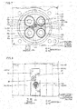
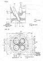
- both the fuel injection portion 51 and the ignition portion 61 are exposed in a central region C1 of the combustion chamber C, as shown in Fig. 3 .
- the central region C1 is a region surrounded by the pair of intake openings 22a and the pair of exhaust openings 23a, and includes the center O of the combustion chamber C.
- the central region C1 is located on the B2 side relative to the center of the pair of intake openings 22a and on the B1 side relative to the center of the pair of exhaust openings 23a in the direction B.
- the central region C1 is located on a Z2 side relative to the centers of the intake opening 22a and the exhaust opening 23a on a Z1 side and on the Z1 side relative to the centers of the intake opening 22a and the exhaust opening 23a on the Z2 side. Moreover, the central region C1 is a region not including the pair of intake openings 22a and the pair of exhaust openings 23a. In Figs. 3 , 7 , and 10 , the central region C1 is shown by diagonal lines.
- the fuel injection portion 51 is disposed so as to inject fuel from the central region C1 into the combustion chamber C.
- the ignition portion 61 is disposed in the central region C1 so as to provide ignition within the combustion chamber C.
- the fuel injection angle of the fuel injection portion 51 is adjusted such that an air-fuel mixture in the combustion chamber C (cylinder 10a) produced by mixing the fuel injected from the fuel injection portion 51 and the intake air that has flowed into the combustion chamber C from the intake openings 22a becomes homogeneous.
- the fuel injection portion 51 is deviated in the direction B from the centerline O2 that passes through the center of the combustion chamber C in the direction B and extends in the upward-downward direction on a centerline (bore centerline) O1 that passes through the center (center O) of the combustion chamber C in the upward-downward direction and extends in the direction B perpendicular to the upward-downward direction.
- the entire fuel injection portion 51 is deviated in the direction B1, in which the pair of intake openings 22a is provided, from the center O (centerline O2) of the combustion chamber C.
- the center of the fuel injection portion 51 is located on the centerline O1 and on the B1 side relative to the centerline O2.
- the ignition portion 61 is deviated in the upward-downward direction from the center O (centerline O1) of the combustion chamber C. Specifically, the entire ignition portion 61 is deviated in a direction Z2 from the centerline O1. The ignition portion 61 is disposed on the center line O2. The center of the ignition portion 61 is located on the Z2 side relative to the centerline O1 and on the B2 side relative to the centerline O2.
- a Z1-side end 61a of the ignition portion 61 and a Z2-side end 51a of the fuel injection portion 51 are disposed at substantially the same position in the upward-downward direction (direction Z). Consequently, the substantially entire ignition portion 61 is disposed on the Z2 side relative to the substantially entire fuel injection portion 51. In the present teaching, it is only required that the center of the ignition portion 61 be deviated in the upward-downward direction relative to the center of the fuel injection portion 51. Furthermore, the Z1-side end 61a of the ignition portion 61 is preferably disposed at substantially the same position as the Z2-side end 51a of the fuel injection portion 51, or on the Z2 side relative to the end 51a.
- the fuel injection portion 51 is disposed between the pair of intake openings 22a spaced apart in the direction Z.
- a B2-side end of the fuel injection portion 51 and B2-side ends of the pair of intake openings 22a are disposed at substantially the same position in the direction B.
- the ignition portion 61 is disposed between the intake opening 22a and the exhaust opening 23a on the Z2 side spaced apart from each other in the direction B.
- the Z1-side end 61a of the ignition portion 61 and a Z1-side end of the exhaust opening 23a on the Z2 side are disposed at substantially the same position in the direction Z.
- Both the fuel injection portion 51 and the ignition portion 61 are disposed near the center O of the combustion chamber C (central region C1).
- the fuel injection portion 51, the ignition portion 61, the pair of intake openings 22a, and the pair of exhaust openings 23a are spaced apart from each other by predetermined distances. Thus, a reduction in the mechanical strength of the cylinder head 20 in the central region C1 is significantly reduced or prevented.
- the fuel injector 50 passes through an insertion hole 20c configured to connect the upper surface (A1-side surface) of the cylinder head 20 in the region R between the pair of valve actuators 31 to the combustion chamber C (central region C1).
- the insertion hole 20c extends in the direction A .
- the fuel injector 50 extends in the direction A in which the cylinder 10a extends.
- a pipe 50a through which fuel is supplied is connected to the A1-side tip of the fuel injector 50.
- the fuel is supplied from a fuel tank (not shown) to the fuel injector 50 through the pipe 50a.
- the fuel injector 50 extends in the direction A in which the cylinder 10a extends such that interference of both the fuel injector 50 and the pipe 50a that extends in the direction A1 from the A1-side tip of the fuel injector 50 with the valve actuators 31 and the valve actuator lid unit 40 is significantly reduced or prevented.
- the spark plug 60 passes through an insertion hole 20d configured to connect the upper surface of the cylinder head 20 in the region R between the pair of valve actuators 31 to the combustion chamber C (central region C1).
- the insertion hole 20d extends in the direction A , and is increasingly inclined in the direction Z2 toward the direction A1. That is, in the region R between the pair of valve actuators 31, the spark plug 60 is inclined in the direction Z2 away from the fuel injector 50 with respect to the direction A .
- the spark plug 60 is disposed so as not to interfere with the fuel injector 50 from the ignition portion 61 on the A2 side to an A1-side end thereof.
- the spark plug 60 is disposed so as not to interfere with components that the outboard motor 100 includes other than the fuel injector 50.
- the inclination angle ⁇ of the spark plug 60 with respect to the direction A is preferably about 45 degrees or less, and more preferably about 30 degrees or less.
- the fuel injectors 50 extend in the direction A1 on the B1 side relative to the centers O (the centerlines O2) of the combustion chambers C.
- the spark plugs 60 are inclined in the direction Z2 with respect to the direction A on the Z2 side relative to the centers O (the centerlines O1) of the combustion chambers C.
- the insertion holes 20a to 20d of the cylinder head 20 are disposed so as to avoid the intake port 22, the exhaust port 23, and a water jacket 20e through which cooling water used to cool the cylinder head 20 flows.
- the fuel injection portion 51 and the ignition portion 61 configured to provide ignition within the combustion chamber C are disposed in the central region C1 of the combustion chamber C between the intake openings 22a and the exhaust openings 23a.
- the liquid fuel is appropriately injected such that the fuel is evenly distributed in the combustion chamber C. Consequently, the distribution of the air-fuel mixture produced by mixing the fuel and the intake air is homogenized in the combustion chamber C.
- the air-fuel mixture homogenized in the combustion chamber C is ignited in the central region C1 of the combustion chamber C.
- the fuel injector 50 and the spark plug 60 are disposed such that a favorable flame front is created while the air-fuel mixture distribution is homogenized, and hence the combustion efficiency of the engine 1 is improved.
- the ignition portion 61 is deviated in the upward-downward direction in which the camshaft 32 extends with respect to the fuel injection portion 51 in the central region C1 of the combustion chamber C between the intake openings 22a and the exhaust openings 23a.
- the outboard motor 100 including the engine 1 in which the fuel injectors 50 and the spark plugs 60 are disposed such that favorable flame fronts are created while the air-fuel mixture distributions are homogenized in a state where constraints on the shape and layout of the valve actuators 31 are reduced is provided.
- the degree of freedom in designing the cylinder head 20 is increased, and hence the intake port 22, the intake openings 22a, the exhaust port 23, the exhaust openings 23a, etc. are largely ensured.
- the spark plug 60 is inclined along the upward-downward direction between the pair of valve actuators 31 in the cylinder head 20.
- the spark plug 60 escapes in the upward-downward direction in which the camshaft 32 extends from the central region C1 of the combustion chamber C, and hence as compared with the case where neither the fuel injector nor the spark plug is inclined along the upward-downward direction, the fuel injector 50 and the spark plug 60 are easily spaced apart from each other while interference of the fuel injector 50 and the spark plug 60 with the valve actuators 31 is significantly reduced or prevented. Consequently, the fuel injector 50 and the spark plug 60 are easily mounted in the cylinder head 20 so as not to interfere with each other in a state where constraints on the shape and layout of the valve actuators 31 are reduced.
- the spark plug 60 is inclined in the direction Z2 away from the fuel injector 50 with respect to the direction A along the upward-downward direction between the pair of valve actuators 31 in the cylinder head 20.
- the fuel injector 50 and the spark plug 60 inclined away from the fuel injector 50 are more easily mounted in the cylinder head 20 so as not to interfere with each other in a state where constraints on the shape and layout of the valve actuators 31 are reduced.
- the spark plug 60 is inclined without inclining the fuel injector 50 such that the spark plug 60 is more easily mounted in an inclined state in the cylinder head 20 as compared with the case where the fuel injector 50 that needs to adjust its fuel injection direction is inclined.
- the ignition portion 61 is deviated in the upward-downward direction (direction Z2) from the center O (centerline O1) of the combustion chamber C in the upward-downward direction.
- the ignition portion 61 is deviated in the upward-downward direction from the centerline O1, and hence the fuel injection portion 51 is easily disposed near the centerline O1 of the combustion chamber C. Consequently, the fuel injection portion 51 is disposed such that the air-fuel mixture is more homogeneously distributed from the vicinity of the centerline O1 of the combustion chamber C to the entirety of the combustion chamber C.
- the fuel injection portion 51 is deviated in the direction B (direction B1) from the center (centerline O2) of the combustion chamber C in the direction B on the centerline O2 that passes through the center O of the combustion chamber C in the upward-downward direction and extends in the direction B perpendicular to the upward-downward direction.
- the fuel injection portion 51 is deviated in the direction B from the centerline O2 of the combustion chamber C, and hence the ignition portion 61 deviated in the upward-downward direction from the centerline O1 is easily disposed near the centerline O2 of the combustion chamber C.
- the fuel injection portion 51 is disposed such that the air-fuel mixture is more homogeneously distributed from the vicinity of the centerline O1 of the combustion chamber C to the entirety of the combustion chamber C, and the ignition portion 61 is disposed such that the combustion more uniformly propagates from the vicinity of the centerline O2 of the combustion chamber C. Therefore, the combustion efficiency of the engine 1 is further improved.
- the intake openings 22a and the exhaust openings 23a are provided on one side (B1 side) and the other side (B2 side) in the direction B with respect to the center (centerline O2) of the combustion chamber C in the direction B, respectively.
- the fuel injection portion 51 is deviated in the direction B1 with respect to the centerline O2.
- the fuel injection portion 51 is disposed away from the vicinity of the exhaust openings 23a, the temperature of which is likely to be high, and hence occurrence of a thermal failure in the fuel injector 50 is significantly reduced or prevented.
- the fuel injector 50 extends in the direction A in which the cylinders (cylinders 10a) of the engine 1 extend between the pair of valve actuators 31 in the cylinder head 20.
- interference of the fuel injector 50 with the pair of valve actuators 31 etc. is further significantly reduced or prevented.
- the position of the fuel injection portion 51 such as the injection angle of the fuel injection portion 51 is easily adjusted such that the air-fuel mixture becomes homogeneous throughout the combustion chamber C.
- the pair of intake openings 22a is provided on the B1 side with respect to the center (centerline O2) of the combustion chamber C in the direction B perpendicular to the upward-downward direction
- the pair of exhaust openings 23a is provided on the B2 side with respect to the centerline O2.
- the central region C1 of the combustion chamber C is provided in the region surrounded by the pair of intake openings 22a and the pair of exhaust openings 23a.
- the fuel injection portion 51 and the ignition portion 61 are disposed in the central region C1 surrounded by the pair of intake openings 22a and the pair of exhaust openings 23a such that the combustion efficiency of the multi-valve engine 1 is further improved.
- the fuel injection portion 51 injects the fuel into the combustion chamber C from between the pair of intake openings 22a provided on the B1 side with respect to the center (centerline O2) of the combustion chamber C in the direction B.
- the ignition portion 61 is disposed between the intake opening 22a and the exhaust opening 23a provided on the Z2 side in the upward-downward direction with respect to the center (centerline O1) of the combustion chamber C in the upward-downward direction.
- the fuel injection portion 51 is disposed such that the fuel is more evenly distributed from the vicinity of the centerline O1 of the combustion chamber C to the entirety of the combustion chamber C, and the ignition portion 61 is disposed such that the combustion more uniformly propagates from the vicinity of the centerline O2 of the combustion chamber C. Consequently, the combustion efficiency of the multi-valve engine 1 is further improved.
- the fuel injection portion 51 injects the fuel into the combustion chamber C from between the pair of intake openings 22a provided on the B1 side with respect to the center (centerline O2) of the combustion chamber C in the direction B.
- the fuel injection portion 51 is disposed away from the vicinity of the exhaust openings 23a, the temperature of which is likely to be high, and hence occurrence of a thermal failure in the fuel injector 50 is significantly reduced or prevented.
- the valve actuators 31 are direct-acting valve actuators including the plurality of cams 33 configured to come into contact with the tappets 24b of a plurality of intake valves 24 or the tappets 25b of a plurality of exhaust valves 25, respectively.
- the valve actuators are rocker arm-type valve actuators including rocker arms that transmit a drive force between the valve actuators and valves. Consequently, the number of components of the engine 1 is reduced, and an increase in the size of the engine 1 is significantly reduced or prevented.
- the fuel injection portion 51 of the fuel injector 50 and the ignition portion 61 configured to provide ignition within the combustion chamber C are disposed in the central region C1 of the combustion chamber C such that the combustion efficiency of the V-type engine 1 is further improved.
- the engine 1 includes a plurality of cylinders (cylinders 10a)
- an increase in the size of the engine 1 in the upward-downward direction in which the cylinders 10a are aligned is significantly reduced or prevented as compared with an in-line engine 1.
- the engine 1 is housed in the cowling 3a in a state where the plurality of cylinders (cylinders 10a) is aligned in the upward-downward direction.
- the spark plug 60 is inclined along the upward-downward direction in which the plurality of cylinders 10a disposed at intervals and likely to have empty spaces therebetween is aligned, and hence interference of the spark plug 60 with another component in the outboard motor 100 is significantly reduced or prevented.
- the spark plug 60 is inclined in the direction Z2 on the Z2 side (side opposite to the timing belt 12) in the cylinder head 20.
- the spark plug 60 is inclined toward a clearance between the engine 1 and a component disposed in the outboard motor 100. Consequently, interference of the spark plug 60 with another component in the outboard motor 100 is significantly reduced or prevented.
- ignition portions 161 are provided on a Z1 side unlike the first preferred embodiment in which the ignition portions 61 are provided on the Z2 side.
- the engine 101 is an example of an "internal combustion engine”.
- the engine 101 includes a pair of cylinder heads 120 each including three recesses 21 in which combustion chambers C are provided.
- the six combustion chambers C have the same structure as in the first preferred embodiment. Therefore, from now on, the structure relating to one combustion chamber C is described in detail, and the description of the structure relating to the other five combustion chambers C is omitted.
- the engine 101 further includes a fuel injector 50 and an spark plug 160 mounted in the cylinder head 120.
- both a fuel injection portion 51 and the ignition portion 161 are exposed in a central region C1 of the combustion chamber C.
- the ignition portion 161 is deviated in an upward-downward direction from the center O (centerline O1) of the combustion chamber C.
- the entire ignition portion 161 is deviated in a direction Z1 from the centerline O1.
- the ignition portion 161 is disposed on a centerline O2.
- the center of the ignition portion 161 is located on the Z1 side relative to the centerline O1 and on a B2 side relative to the centerline O2.
- a Z2-side end 161a of the ignition portion 161 and a Z2-side end 51a of the fuel injection portion 51 are disposed at substantially the same position in the upward-downward direction (direction Z). Consequently, the substantially entire ignition portion 161 is disposed on the Z1 side relative to the substantially entire fuel injection portion 51
- the ignition portion 161 is disposed between an intake opening 22a and an exhaust opening 23a on the Z1 side spaced apart from each other in a direction B.
- the Z2-side end 161a of the ignition portion 161 and Z2-side ends of the intake opening 22a and the exhaust opening 23a on the Z1 side are disposed at substantially the same position in the direction Z.
- the spark plug 160 passes through an insertion hole 120d configured to connect the upper surface (A1-side surface) of the cylinder head 120 to the combustion chamber C (the central region C1).
- the insertion hole 120d extends in a direction A and is increasingly inclined in the direction Z1 toward a direction A1. That is, the spark plug 160 is inclined in the direction Z1 away from the fuel injector 50 with respect to the direction A in a region R between a pair of valve actuators 31.
- the spark plug 160 is disposed so as not to interfere with the fuel injector 50 from the ignition portion 161 on an A2 side to the A1-side end thereof.
- the spark plug 160 is disposed so as not to interfere with components that the outboard motor 200 includes other than the fuel injector 50.
- the spark plugs 160 are inclined in the direction Z1 with respect to the direction A on the Z1 side relative to the centers O (the centerlines O1) of the combustion chambers C.
- the remaining structures of the second preferred embodiment are similar to those of the first preferred embodiment.
- the fuel injection portion 51 and the ignition portion 161 configured to provide ignition within the combustion chamber C are disposed in the central region C1 of the combustion chamber C. Furthermore, the ignition portion 161 is deviated in the upward-downward direction in which a camshaft 32 extends with respect to the fuel injection portion 51 in the central region C1 of the combustion chamber C between intake openings 22a and exhaust openings 23a.
- the outboard motor 200 including the engine 101 in which the fuel injectors 50 and the spark plugs 160 are disposed such that favorable flame fronts are created while air-fuel mixture distributions are homogenized in a state where constraints on the shape and layout of the valve actuators 31 are reduced is provided.
- the spark plug 160 is inclined in the direction Z1 on the Z1 side (side closer to a timing belt 12) in the cylinder head 120.
- the spark plug 160 is inclined toward a clearance between the engine 101 and the timing belt 12 Consequently, interference of the spark plug 160 with another component in the outboard motor 200 is significantly reduced or prevented.
- the remaining advantageous effects of the second preferred embodiment are similar to those of the first preferred embodiment.
- the structure of an engine 201 of an outboard motor 300 according to a third preferred embodiment is now described with reference to Figs. 1 , 10 , and 11 .
- the structure of the first preferred embodiment in which the ignition portions 61 are provided on the Z2 side and the structure of the second preferred embodiment in which the ignition portions 161 are provided on the Z1 side are combined.
- the engine 201 is an example of an "internal combustion engine”.
- the engine 201 includes a pair of cylinder heads 220 each including three recesses 21 in which combustion chambers C are provided.
- the six combustion chambers C have the same structure as in the first preferred embodiment. Therefore, from now on, the structure relating to one combustion chamber C is described in detail, and the description of the structure relating to the other five combustion chambers C is omitted.
- the engine 201 further includes a fuel injector 50 and spark plugs 60 and 160 mounted in the cylinder head 220. That is, according to the third preferred embodiment, a pair of ignitions 60 and 160 is provided for one combustion chamber C.
- the spark plugs 60 and 160 are examples of a "first spark plug” and a “second spark plug”, respectively.
- all of an fuel injection portion 51, an ignition portion 61 of the spark plug 60, and an ignition portion 161 of the spark plug 160 are exposed in a central region C1 of the combustion chamber C.
- the ignition portions 61 and 161 are deviated in an upward-downward direction from the center O of the combustion chamber C.
- the entire ignition portion 61 and the entire ignition portion 161 are deviated in a direction Z2 and a direction Z1 from the center O (centerline O1) of the combustion chamber C, respectively.
- the ignition portions 61 and 161 are disposed on a centerline O2.
- the center of the ignition portion 61 and the center of the ignition portion 161 are located on a Z2 side and a Z1 side relative to the centerline O1, respectively, and are located on a B2 side relative to the centerline O2.
- the substantially entire ignition portion 61 and the substantially entire ignition portion 161 are disposed on the Z2 side and the Z1 side, respectively, relative to the substantially entire fuel injection portion 51.
- the ignition portions 61 and 161 are examples of a "first ignition portion” and a "second ignition portion", respectively.
- the spark plugs 60 and 160 are inclined in the directions Z2 and Z1 away from the fuel injector 50 with respect to the direction A , respectively, in a region R between a pair of valve actuators 31.
- the spark plug 60 is disposed so as not to interfere with the fuel injector 50 etc. from the ignition portion 61 on an A2 side to an A1-side end thereof.
- the spark plug 160 is disposed so as not to interfere with the fuel injector 50 etc. from the ignition portion 161 on the A2 side to an A1-side end thereof.
- the spark plugs 60 are inclined in the direction Z2 with respect to the direction A on the Z2 side relative to the centers O (the centerlines O1) of the combustion chambers C.
- the spark plugs 160 are inclined in the direction Z1 with respect to the direction A on the Z2 side relative to the centerlines O1.
- the remaining structures of the third preferred embodiment are similar to those of the first preferred embodiment and the second preferred embodiment.
- the fuel injection portion 51 and the ignition portions 61 and 161 configured to provide ignition within the combustion chamber C are disposed in the central region C1 of the combustion chamber C. Furthermore, the ignition portions 61 and 161 are deviated in the upward-downward direction in which a camshaft 32 extends with respect to the fuel injection portion 51 in the central region C1 of the combustion chamber C between intake openings 22a and exhaust openings 23a.
- the outboard motor 300 including the engine 201 in which the fuel injectors 50 and the spark plugs 60 and 160 are disposed such that favorable flame fronts are created while air-fuel mixture distributions are homogenized in a state where constraints on the shape and layout of the valve actuators 31 are reduced is provided.
- the outboard motor 300 includes the spark plug 60 including the ignition portion 61 deviated in the direction Z2 in the upward-downward direction with respect to the fuel injection portion 51 in the central region C1 and configured to provide ignition within the combustion chamber C, and inclined in the direction Z2 away from the fuel injector 50 toward the direction Z2 in the upward-downward direction between the pair of valve actuators 31 in the cylinder head 220.
- the outboard motor 300 further includes the spark plug 160 including the ignition portion 161 deviated in the direction Z1 in the upward-downward direction with respect to the fuel injection portion 51 in the central region C1 and configured to provide ignition within the combustion chamber C, and inclined in the direction Z1 away from the fuel injector 50 toward the direction Z1 in the upward-downward direction between the pair of valve actuators 31 in the cylinder head 220.
- the fuel injector 50 and the plurality of spark plugs 60 and 160 are easily mounted in the cylinder head 220 so as not to interfere with each other.
- the plurality of spark plugs 60 and 160 is provided such that combustion in the combustion chamber C more uniformly propagates due to two-point ignition.
- the remaining advantageous effects of the third preferred embodiment are similar to those of the first preferred embodiment and the second preferred embodiment.
- the structure of an engine 301 of an outboard motor 400 according to a fourth preferred embodiment is now described with reference to Figs. 1 , 3 , and 12 .
- fuel injectors 350 are inclined unlike the fuel injectors 50 according to the first preferred embodiment.
- the engine 301 is an example of an "internal combustion engine”.
- the engine 301 includes a pair of cylinder heads 320 each including three recesses 21 in which combustion chambers C are provided.
- the six combustion chambers C have the same structure as in the first preferred embodiment. Therefore, from now on, the structure relating to one combustion chamber C is described in detail, and the description of the structure relating to the other five combustion chambers C is omitted.
- the engine 301 further includes the fuel injector 350 and an spark plug 60 (see Fig. 3 ) mounted in the cylinder head 320. Both a fuel injection portion 51 of the fuel injector 350 and an ignition portion 61 (see Fig. 3 ) are exposed in a central region C1 (see Fig. 3 ) of the combustion chamber C.
- the fuel injector 350 passes through an insertion hole 320c configured to connect the upper surface (A1-side surface) of the cylinder head 320 in a region R between a pair of valve actuators 31 to the combustion chamber C (central region C1).
- the insertion hole 320c extends in a direction A and is increasingly inclined in a direction B1 toward a direction A1. That is, the fuel injector 350 is inclined in the direction B1 on a side closer to an intake port 22 with respect to the direction A in the region R between the pair of valve actuators 31.
- the fuel injector 350 is disposed such that both the fuel injector 350 and a pipe 350a that extends in the direction A1 from the A1-side tip of the fuel injector 350 avoid the valve actuators 31 and a valve actuator lid unit 40.
- the remaining structures of the fourth preferred embodiment are similar to those of the first preferred embodiment.
- the fuel injection portion 51 and the ignition portion 61 configured to provide ignition within the combustion chamber C are disposed in the central region C1 of the combustion chamber C. Furthermore, the ignition portion 61 is deviated in an upward-downward direction in which a camshaft 32 extends with respect to the fuel injection portion 51 in the central region C1 of the combustion chamber C between intake openings 22a and exhaust openings 23a.
- the outboard motor 400 including the engine 301 in which the fuel injectors 350 and the spark plugs 60 are disposed such that favorable flame fronts are created while air-fuel mixture distributions are homogenized in a state where constraints on the shape and layout of the valve actuators 31 are reduced is provided.
- the fuel injector 350 is inclined with respect to the direction A in which a cylinder 10a extends along the direction B perpendicular to the upward-downward direction in a state where the fuel injector 350 avoids the pair of valve actuators 31 and the valve actuator lid unit 40 in the region R between the pair of valve actuators 31 of the cylinder head 320.
- an increase in the length of the fuel injector 350 in the direction A is significantly reduced or prevented while interference of the fuel injector 350 with the pair of valve actuators 31 and the valve actuator lid unit 40 is significantly reduced or prevented.
- the remaining advantageous effects of the fourth preferred embodiment are similar to those of the first preferred embodiment.
- the engine 1, 101, 201, or 301 is preferably a V-type engine including six cylinders (cylinders 10a) in each of the first, second, third, and fourth preferred embodiments described above, the present teaching is not restricted to this.
- the internal combustion engine may alternatively include one or more and five or less cylinders or may alternatively include seven or more cylinders.
- the internal combustion engine may alternatively be an in-line engine in which a plurality of cylinders is disposed in series.
- the internal combustion engine may alternatively be configured by appropriately combining the combustion chamber C according to the first preferred embodiment, in which the spark plug 60 including the ignition portion 61 provided on the Z2 side and inclined in the direction Z2 is provided, the combustion chamber C according to the second preferred embodiment, in which the spark plug 160 including the ignition portion 161 provided on the Z1 side and inclined in the direction Z1 is provided, and the combustion chamber C according to the third preferred embodiment, in which both the spark plug 60 and the spark plug 160 are provided.
- the structure of the inclined fuel injector 350 according to the fourth preferred embodiment may alternatively be applied. That is, in the structure of the second or third preferred embodiment, the fuel injector may be inclined.
- the fuel injector 50 (350) and the spark plug 60 (160) may alternatively be interchanged.
- the spark plug may extend in the direction A1 on the B1 side relative to the center O (the centerline O2) of the combustion chamber C.
- the fuel injector may be inclined in the direction Z2 with respect to the direction A on the Z2 side relative to the center O (the centerline O1) of the combustion chamber C.
- the fuel injector 50 (350) is preferably provided on the side closer to the intake port 22 (B1 side) in each of the first to fourth preferred embodiments described above, the present teaching is not restricted to this.
- the fuel injector may alternatively be provided on a side closer to the exhaust port.
- the fuel injection portion 51 is preferably disposed on the centerline O1 that passes through the center O of the combustion chamber C (central region C1) and extends in the direction B (second direction) in each of the first to fourth preferred embodiments described above, the present teaching is not restricted to this.
- the fuel injection portion may alternatively be disposed above or below the centerline that extends in the second direction instead of on the centerline that extends in the second direction so far as the same is disposed in the central region.
- the fuel injection portion is preferably disposed near the centerline that extends in the second direction.
- the fuel injection portion is preferably spaced sufficiently apart from the ignition portion in the upward-downward direction.
- the fuel injection portion is preferably disposed in the other side in the upward-downward direction with respect to the center of the combustion chamber in the second direction.
- the ignition portion 61 (161) is preferably disposed on the B2 side (side closer to the exhaust port 23) relative to the centerline O2 that passes through the center O of the combustion chamber C (central region C1) and extends in the direction Z (upward-downward direction) in each of the first to fourth preferred embodiments described above, the present teaching is not restricted to this.
- the ignition portion may alternatively be disposed on the centerline of the combustion chamber that extends in the upward-downward direction or may alternatively be disposed on the side closer to the intake port relative to the centerline that extends in the upward-downward direction so far as the same is disposed in the central region.
- the ignition portion is preferably spaced sufficiently apart from the fuel injection portion in the upward-downward direction.
- the present teaching is preferably applied to the multi-valve engine 1 (101, 201, 301) (internal combustion engine) including the pair of intake openings 22a and the pair of exhaust openings 23a, in which valves are disposed, for one combustion chamber C in each of the first to fourth preferred embodiments described above, the present teaching is not restricted to this.
- the present teaching may alternatively be applied to a single-valve internal combustion engine including one intake opening and one exhaust opening, in which valves are disposed, for one combustion chamber.
- the fuel injection portion of the fuel injector and the ignition portion of the spark plug are deviated from each other in the upward-downward direction in a central region between one intake opening and one exhaust opening.
- the fuel injection portion 51 of the fuel injector 50 (350) is preferably directly exposed in the combustion chamber C in each of the first to fourth preferred embodiments described above, the present teaching is not restricted to this.
- the fuel injection portion of the fuel injector may alternatively be disposed in the insertion hole (insertion hole 20c in Fig. 5 ) of the cylinder head so as not to be exposed in the combustion chamber.
- the injection direction of the fuel injected from the fuel injection portion is adjusted by adjusting the orientation of the insertion hole, for example. It is necessary to locate an opening of the insertion hole closer to the combustion chamber in the central region of the combustion chamber.
- spark plug 60 is preferably inclined with respect to the direction A (first direction in which the cylinder extends) along the upward-downward direction in each of the first to fourth preferred embodiments described above, the present teaching is not restricted to this.
- the inclination direction of the spark plug is not particularly restricted.
- the spark plug may alternatively be inclined in the second direction other than the upward-downward direction.
- the spark plug is preferably inclined in the direction away from the fuel injector.
- the fuel injector 350 is preferably inclined with respect to the direction A along the direction B (second direction) in the fourth preferred embodiment described above, the present teaching is not restricted to this.
- the inclination direction of the fuel injector is not particularly restricted.
- the fuel injector may alternatively be inclined in the upward-downward direction other than the second direction other than the upward-downward direction.
- the fuel injector is preferably inclined in a direction away from the spark plug.
Landscapes
- Engineering & Computer Science (AREA)
- Chemical & Material Sciences (AREA)
- Combustion & Propulsion (AREA)
- Mechanical Engineering (AREA)
- General Engineering & Computer Science (AREA)
- Ocean & Marine Engineering (AREA)
- Cylinder Crankcases Of Internal Combustion Engines (AREA)
- Fuel-Injection Apparatus (AREA)
- Ignition Installations For Internal Combustion Engines (AREA)
- Combustion Methods Of Internal-Combustion Engines (AREA)
Claims (15)
- Außenbordmotor (100), der umfasst:einen Verbrennungsmotor (1);eine Verkleidung (3a), in der der Verbrennungsmotor (1) aufgenommen ist; undeine Antriebseinheit (2), die so ausgeführt ist, dass sie eine Dreh-Antriebskraft des Verbrennungsmotors (1) in eine Vorschubkraft umwandelt; wobeider Verbrennungsmotor (1) enthält:einen Zylinderkopf (20), der eine Ansaugöffnung (22a), über die Ansaugluft in eine Brennkammer (C) eines Zylinders (10a) eingeleitet wird, sowie eine Abgasöffnung (23a) enthält, über die Abgas aus der Brennkammer (C) abgeleitet wird;eine Vielzahl von Ventilen (24, 25), die zum Öffnen und Schließen der Ansaugöffnung (22a) und der Abgasöffnung (23a) ausgeführt sind;ein Paar Ventil-Antriebseinrichtungen (31), die in Entsprechung zu dem Zylinderkopf (20) vorhanden sind, die jeweils eine Nockenwelle (32) einschließen und so ausgeführt sind, dass sie eine Antriebskraft auf die Vielzahl von Ventilen (24, 25) übertragen; dadurch gekennzeichnet, dass der Außenbordmotor (100) des Weiteren umfasst:eine Kraftstoffeinspritzeinrichtung (50), die einen Kraftstoffeinspritz-Abschnitt (51) enthält, der so ausgeführt ist, dass er Kraftstoff aus einem mittigen Bereich (C1) der Brennkammer (C) zwischen der Ansaugöffnung (22a) und der Abgasöffnung (23a) in die Brennkammer (C) einspritzt, wobei die Kraftstoffeinspritzeinrichtung (50) in dem Zylinderkopf (20) installiert ist; undeine Zündkerze (60), die einen Zündabschnitt (61), der in Bezug auf den Kraftstoffeinspritzabschnitt (51) in dem mittigen Bereich (C1) in der Richtung der Nockenwelle (32) versetzt angeordnet und so ausgeführt ist, dass er Zündung im Inneren der Brennkammer (C) bewirkt, wobei die Zündkerze (60) in dem Zylinderkopf (20) installiert ist.
- Außenbordmotor (100) nach Anspruch 1, wobei die Kraftstoffeinspritzeinrichtung (50) oder/und die Zündkerze (60) in Bezug auf eine erste Richtung, in der sich der Zylinder (10a) des Verbrennungsmotors (1) erstreckt, in der vertikalen Richtung zwischen den paarigen Ventil-Antriebseinrichtungen (31) in dem Zylinderkopf (20) geneigt ist/sind.
- Außenbordmotor (100) nach Anspruch 2, wobei die Zündkerze (60) in der vertikalen Richtung zwischen den paarigen Ventil-Antriebseinrichtungen (31) in dem Zylinderkopf (20) von der Kraftstoffeinspritzeinrichtung (50) weg geneigt ist.
- Außenbordmotor (100) nach einem der Ansprüche 1 bis 3, wobei der Zündabschnitt (61) in der vertikalen Richtung von einer Mitte der Brennkammer (C) in der vertikalen Richtung abweicht.
- Außenbordmotor (100) nach Anspruch 4, wobei der Einspritzabschnitt (51) in einer zweiten Richtung senkrecht zu der vertikalen Richtung von einer Mitte der Brennkammer (C) in der zweiten Richtung auf einer Mittellinie (O2) abweicht, die durch die Mitte der Brennkammer (C) in der vertikalen Richtung verläuft und sich in der zweiten Richtung oder in der Nähe der Mittellinie erstreckt.
- Außenbordmotor (100) nach Anspruch 5, wobei
die Ansaugöffnung (22a) und die Abgasöffnung (23a) sich jeweils an einer Seite und der anderen Seite in der zweiten Richtung in Bezug auf die Mitte der Brennkammer (C) in der zweiten Richtung befinden; und
der Einspritzabschnitt (51) zu der einen Seite in der zweiten Richtung in Bezug auf die Mitte der Brennkammer (C) in der zweiten Richtung abweicht. - Außenbordmotor (100) nach einem der Ansprüche 1 bis 6, wobei sich die Kraftstoffeinspritzeinrichtung (50) in einer ersten Richtung erstreckt, in der sich der Zylinder (10a) des Verbrennungsmotors (1) zwischen den paarigen Ventil-Antriebseinrichtungen (31) in dem Zylinderkopf (20) erstreckt.
- Außenbordmotor (100) nach einem der Ansprüche 1 bis 6, wobei
der Verbrennungsmotor (1) des Weiteren eine Ventilantriebsabdeckungs-Einheit (410) enthält, die so ausgeführt ist, dass sie die paarigen Ventil-Antriebseinrichtungen (31) abdeckt; und
die Kraftstoffeinspritzeinrichtung (50) in Bezug auf eine erste Richtung, in der sich der Zylinder (10a) des Verbrennungsmotors (1) in einer zweiten Richtung senkrecht zu der vertikalen Richtung erstreckt, in einem Zustand geneigt ist, in dem die Kraftstoffeinspritzeinrichtung (50) die paarigen Ventil-Antriebseinrichtungen (31) und die Ventilantriebsabdeckungs-Einheit zwischen den paarigen Ventil-Antriebseinrichtungen (31) in dem Zylinderkopf (20) umgeht. - Außenbordmotor (100) nach Anspruch 3, wobei
die Zündkerze (60) einschließt:eine erste Zündkerze (60), die einen ersten Zündabschnitt (61) enthält, der in der vertikalen Richtung in Bezug auf den Einspritzabschnitt (51) in dem mittigen Bereich (C1) zu einer Seite abweicht, und so ausgeführt ist, dass sie eine Zündkerze (60) im Inneren der Brennkammer (C) bildet, wobei die erste Zündkerze (60) in der vertikalen Richtung zwischen den paarigen Ventil-Antriebseinrichtungen (31) in dem Zylinderkopf (20) von der Kraftstoffeinspritzeinrichtung (50) weg zu der einen Seite geneigt ist; undeine zweite Zündkerze (160), die einen zweiten Zündabschnitt (161) enthält, der in der vertikalen Richtung in Bezug auf den Einspritzabschnitt (51) in dem mittigen Bereich (C1) zu der anderen Seite abweicht, und so ausgeführt ist, dass sie Zündung im Inneren der Brennkammer (C) bewirkt, wobei die zweite Zündkerze (160) in der vertikalen Richtung zwischen den paarigen Ventil-Antriebseinrichtungen (31) in dem Zylinderkopf (20) von der Kraftstoffeinspritzeinrichtung (50) weg zu der anderen Seite geneigt ist. - Außenbordmotor (100) nach einem der Ansprüche 1 bis 9, wobei
die Ansaugöffnung (22a) paarige Ansaugöffnungen (22a) einschließt, die sich an einer Seite in einer zweiten Richtung senkrecht zu der vertikalen Richtung in Bezug auf eine Mitte der Brennkammer (C) in der zweiten Richtung befinden;
die Abgasöffnung (23a) paarige Abgasöffnungen (23a) einschließt, die sich an der anderen Seite in der zweiten Richtung in Bezug auf die Mitte der Brennkammer (C) in der zweiten Richtung befinden; und
der mittige Bereich (C1) der Brennkammer (C) sich in einem Bereich befindet, der von den paarigen Ansaugöffnungen (22a) und den paarigen Abgasöffnungen (23a) umgeben ist. - Außenbordmotor (100) nach Anspruch 10, wobei
der Einspritzabschnitt (51) den Kraftstoff in die Brennkammer (C) zwischen den paarigen Ansaugöffnungen (22a), die sich an der einen Seite in der zweiten Richtung in Bezug auf die Mitte der Brennkammer (C) in der zweiten Richtung befinden, oder zwischen den paarigen Abgasöffnungen (23a) einspritzt, die sich an der anderen Seite in der zweiten Richtung in Bezug auf die Mitte der Brennkammer (C) in der zweiten Richtung befinden; und
der Zündabschnitt (61) zwischen der Ansaugöffnung (22a) und der Abgasöffnung (23a) angeordnet ist, die sich an einer Seite in der vertikalen Richtung in Bezug auf eine Mitte der Brennkammer (C) in der vertikalen Richtung befinden. - Außenbordmotor (100) nach Anspruch 11, wobei der Einspritzabschnitt (51) den Kraftstoff zwischen den paarigen Ansaugöffnungen (22a), die sich an der einen Seite in der zweiten Richtung in Bezug auf die Mitte der Brennkammer (C) in der zweiten Richtung befinden, in die Brennkammer (C) einspritzt.
- Außenbordmotor (100) nach einem der Ansprüche 1 bis 12, wobei die Ventil-Antriebseinrichtungen (31) direkt wirkende Ventil-Antriebseinrichtungen (31) sind, die eine Vielzahl von Nocken aufweisen, die so ausgeführt sind, dass sie jeweils mit Nocken-Kontakten (24b, 25b) der Vielzahl von Ventilen (24, 25) in Kontakt kommen.
- Außenbordmotor (100) nach einem der Ansprüche 1 bis 13, wobei der Verbrennungsmotor (1) ein V-Verbrennungsmotor (1) ist.
- Außenbordmotor (100) nach Anspruch 2, wobei der Verbrennungsmotor (1) in der Verkleidung in einem Zustand aufgenommen ist, in dem eine Vielzahl der Zylinder in der vertikalen Richtung ausgerichtet sind.
Applications Claiming Priority (1)
| Application Number | Priority Date | Filing Date | Title |
|---|---|---|---|
| JP2016254854A JP2018105279A (ja) | 2016-12-28 | 2016-12-28 | 船外機 |
Publications (3)
| Publication Number | Publication Date |
|---|---|
| EP3354875A2 EP3354875A2 (de) | 2018-08-01 |
| EP3354875A3 EP3354875A3 (de) | 2018-09-19 |
| EP3354875B1 true EP3354875B1 (de) | 2019-10-09 |
Family
ID=60480210
Family Applications (1)
| Application Number | Title | Priority Date | Filing Date |
|---|---|---|---|
| EP17203757.4A Active EP3354875B1 (de) | 2016-12-28 | 2017-11-27 | Aussenbordmotor |
Country Status (3)
| Country | Link |
|---|---|
| US (1) | US10286988B2 (de) |
| EP (1) | EP3354875B1 (de) |
| JP (1) | JP2018105279A (de) |
Families Citing this family (1)
| Publication number | Priority date | Publication date | Assignee | Title |
|---|---|---|---|---|
| JP2024054727A (ja) | 2022-10-05 | 2024-04-17 | ヤマハ発動機株式会社 | 船舶推進器および船舶推進器の制御方法 |
Family Cites Families (7)
| Publication number | Priority date | Publication date | Assignee | Title |
|---|---|---|---|---|
| JP2002511549A (ja) * | 1998-04-10 | 2002-04-16 | ルノー | 制御された点火および直接噴射を有する内燃エンジン |
| US7028662B2 (en) | 2003-11-06 | 2006-04-18 | Nissan Motor Co., Ltd. | Direct fuel injection engine |
| JP2006052666A (ja) | 2004-08-11 | 2006-02-23 | Nissan Motor Co Ltd | 筒内直接噴射式内燃機関 |
| IT1395644B1 (it) * | 2009-05-27 | 2012-10-16 | Bitmanufaktur Gmbh | Dispositivo hardware wireless per il rilevamento di relazioni di distanza, e sistema di monitoraggio di relazioni di distanza tra dispositivi hardware wireless |
| JP5850461B2 (ja) * | 2010-02-11 | 2016-02-03 | セブン マリーン, エルエルシーSeven Marine, LLC | 船舶用の大型船外モータおよびその製造方法並びに運用方法 |
| JP5308477B2 (ja) | 2011-05-24 | 2013-10-09 | ヤマハ発動機株式会社 | 4サイクルエンジン |
| JP2016160836A (ja) | 2015-03-02 | 2016-09-05 | ヤマハ発動機株式会社 | 船外機 |
-
2016
- 2016-12-28 JP JP2016254854A patent/JP2018105279A/ja active Pending
-
2017
- 2017-11-22 US US15/820,502 patent/US10286988B2/en active Active
- 2017-11-27 EP EP17203757.4A patent/EP3354875B1/de active Active
Non-Patent Citations (1)
| Title |
|---|
| None * |
Also Published As
| Publication number | Publication date |
|---|---|
| EP3354875A3 (de) | 2018-09-19 |
| JP2018105279A (ja) | 2018-07-05 |
| US20180178892A1 (en) | 2018-06-28 |
| US10286988B2 (en) | 2019-05-14 |
| EP3354875A2 (de) | 2018-08-01 |
Similar Documents
| Publication | Publication Date | Title |
|---|---|---|
| US10150548B2 (en) | Outboard motor and marine vessel | |
| JP5806899B2 (ja) | 内燃機関 | |
| EP0603924B1 (de) | Zylinderkopf für eine Brennkraftmaschine | |
| JP2766292B2 (ja) | エンジンの動弁装置 | |
| WO2003095824A1 (en) | Fuel pump mounting structure of fuel injection engine | |
| EP0967370A2 (de) | Brennkraftmaschine | |
| US10286988B2 (en) | Outboard motor and marine vessel | |
| JP2003129921A (ja) | 船外機用4サイクルエンジン | |
| EP0682176B1 (de) | Brennkraftmaschine | |
| US7380533B2 (en) | Outboard motor provided with internal combustion engine having electrical equipment box | |
| CN102536368B (zh) | 包括带有独立凸轮定相的凸轮轴的发动机组件 | |
| US6338660B1 (en) | Exhaust system for an outboard motor | |
| EP1749997B1 (de) | Brennkraftmaschine mit Kraftstoffeinspritzung | |
| JP3319643B2 (ja) | エンジンの吸気制御装置 | |
| EP1344930B1 (de) | Brennkraftmaschine mit Kraftstoffeinspritzventil | |
| US20020017272A1 (en) | Internal combustion engine | |
| EP1626167A2 (de) | Brennkraftmaschine mit Direkteinspritzung | |
| EP1243760A2 (de) | Brennkraftmaschine | |
| US10690086B2 (en) | Direct fuel injection, two-valve per cylinder pushrod valvetrain combustion system for an internal combustion engine | |
| US6782864B2 (en) | Mount structure for an engine accessory | |
| JP3784920B2 (ja) | 筒内噴射ガソリンエンジン | |
| US10309339B2 (en) | Internal combustion engine | |
| GB2296292A (en) | Spark-ignition i.c.engine | |
| JPH06117327A (ja) | エンジンのシリンダヘッド構造 | |
| JP3323315B2 (ja) | エンジンの吸気制御装置 |
Legal Events
| Date | Code | Title | Description |
|---|---|---|---|
| PUAI | Public reference made under article 153(3) epc to a published international application that has entered the european phase |
Free format text: ORIGINAL CODE: 0009012 |
|
| STAA | Information on the status of an ep patent application or granted ep patent |
Free format text: STATUS: THE APPLICATION HAS BEEN PUBLISHED |
|
| AK | Designated contracting states |
Kind code of ref document: A2 Designated state(s): AL AT BE BG CH CY CZ DE DK EE ES FI FR GB GR HR HU IE IS IT LI LT LU LV MC MK MT NL NO PL PT RO RS SE SI SK SM TR |
|
| AX | Request for extension of the european patent |
Extension state: BA ME |
|
| PUAL | Search report despatched |
Free format text: ORIGINAL CODE: 0009013 |
|
| AK | Designated contracting states |
Kind code of ref document: A3 Designated state(s): AL AT BE BG CH CY CZ DE DK EE ES FI FR GB GR HR HU IE IS IT LI LT LU LV MC MK MT NL NO PL PT RO RS SE SI SK SM TR |
|
| AX | Request for extension of the european patent |
Extension state: BA ME |
|
| RIC1 | Information provided on ipc code assigned before grant |
Ipc: F02B 61/04 20060101AFI20180815BHEP Ipc: B63H 20/24 20060101ALI20180815BHEP Ipc: B63H 20/28 20060101ALI20180815BHEP Ipc: F01P 3/20 20060101ALI20180815BHEP Ipc: F02B 75/22 20060101ALI20180815BHEP |
|
| STAA | Information on the status of an ep patent application or granted ep patent |
Free format text: STATUS: REQUEST FOR EXAMINATION WAS MADE |
|
| 17P | Request for examination filed |
Effective date: 20181011 |
|
| RBV | Designated contracting states (corrected) |
Designated state(s): AL AT BE BG CH CY CZ DE DK EE ES FI FR GB GR HR HU IE IS IT LI LT LU LV MC MK MT NL NO PL PT RO RS SE SI SK SM TR |
|
| STAA | Information on the status of an ep patent application or granted ep patent |
Free format text: STATUS: EXAMINATION IS IN PROGRESS |
|
| 17Q | First examination report despatched |
Effective date: 20181218 |
|
| REG | Reference to a national code |
Ref country code: DE Ref legal event code: R079 Ref document number: 602017007657 Country of ref document: DE Free format text: PREVIOUS MAIN CLASS: F02B0061040000 Ipc: F01P0003020000 |
|
| GRAP | Despatch of communication of intention to grant a patent |
Free format text: ORIGINAL CODE: EPIDOSNIGR1 |
|
| STAA | Information on the status of an ep patent application or granted ep patent |
Free format text: STATUS: GRANT OF PATENT IS INTENDED |
|
| RIC1 | Information provided on ipc code assigned before grant |
Ipc: F02B 75/22 20060101ALI20190509BHEP Ipc: F02B 61/04 20060101ALI20190509BHEP Ipc: F01P 3/20 20060101ALI20190509BHEP Ipc: B63H 20/00 20060101ALI20190509BHEP Ipc: F02F 1/24 20060101ALI20190509BHEP Ipc: F02F 1/38 20060101ALI20190509BHEP Ipc: F01P 3/02 20060101AFI20190509BHEP Ipc: F01P 3/16 20060101ALI20190509BHEP |
|
| INTG | Intention to grant announced |
Effective date: 20190527 |
|
| GRAS | Grant fee paid |
Free format text: ORIGINAL CODE: EPIDOSNIGR3 |
|
| GRAA | (expected) grant |
Free format text: ORIGINAL CODE: 0009210 |
|
| STAA | Information on the status of an ep patent application or granted ep patent |
Free format text: STATUS: THE PATENT HAS BEEN GRANTED |
|
| AK | Designated contracting states |
Kind code of ref document: B1 Designated state(s): AL AT BE BG CH CY CZ DE DK EE ES FI FR GB GR HR HU IE IS IT LI LT LU LV MC MK MT NL NO PL PT RO RS SE SI SK SM TR |
|
| REG | Reference to a national code |
Ref country code: GB Ref legal event code: FG4D |
|
| REG | Reference to a national code |
Ref country code: CH Ref legal event code: EP |
|
| REG | Reference to a national code |
Ref country code: IE Ref legal event code: FG4D |
|
| REG | Reference to a national code |
Ref country code: DE Ref legal event code: R096 Ref document number: 602017007657 Country of ref document: DE |
|
| REG | Reference to a national code |
Ref country code: AT Ref legal event code: REF Ref document number: 1189078 Country of ref document: AT Kind code of ref document: T Effective date: 20191115 |
|
| REG | Reference to a national code |
Ref country code: NL Ref legal event code: MP Effective date: 20191009 |
|
| REG | Reference to a national code |
Ref country code: LT Ref legal event code: MG4D |
|
| REG | Reference to a national code |
Ref country code: AT Ref legal event code: MK05 Ref document number: 1189078 Country of ref document: AT Kind code of ref document: T Effective date: 20191009 |
|
| PG25 | Lapsed in a contracting state [announced via postgrant information from national office to epo] |
Ref country code: PL Free format text: LAPSE BECAUSE OF FAILURE TO SUBMIT A TRANSLATION OF THE DESCRIPTION OR TO PAY THE FEE WITHIN THE PRESCRIBED TIME-LIMIT Effective date: 20191009 Ref country code: LT Free format text: LAPSE BECAUSE OF FAILURE TO SUBMIT A TRANSLATION OF THE DESCRIPTION OR TO PAY THE FEE WITHIN THE PRESCRIBED TIME-LIMIT Effective date: 20191009 Ref country code: NL Free format text: LAPSE BECAUSE OF FAILURE TO SUBMIT A TRANSLATION OF THE DESCRIPTION OR TO PAY THE FEE WITHIN THE PRESCRIBED TIME-LIMIT Effective date: 20191009 Ref country code: BG Free format text: LAPSE BECAUSE OF FAILURE TO SUBMIT A TRANSLATION OF THE DESCRIPTION OR TO PAY THE FEE WITHIN THE PRESCRIBED TIME-LIMIT Effective date: 20200109 Ref country code: FI Free format text: LAPSE BECAUSE OF FAILURE TO SUBMIT A TRANSLATION OF THE DESCRIPTION OR TO PAY THE FEE WITHIN THE PRESCRIBED TIME-LIMIT Effective date: 20191009 Ref country code: SE Free format text: LAPSE BECAUSE OF FAILURE TO SUBMIT A TRANSLATION OF THE DESCRIPTION OR TO PAY THE FEE WITHIN THE PRESCRIBED TIME-LIMIT Effective date: 20191009 Ref country code: NO Free format text: LAPSE BECAUSE OF FAILURE TO SUBMIT A TRANSLATION OF THE DESCRIPTION OR TO PAY THE FEE WITHIN THE PRESCRIBED TIME-LIMIT Effective date: 20200109 Ref country code: LV Free format text: LAPSE BECAUSE OF FAILURE TO SUBMIT A TRANSLATION OF THE DESCRIPTION OR TO PAY THE FEE WITHIN THE PRESCRIBED TIME-LIMIT Effective date: 20191009 Ref country code: GR Free format text: LAPSE BECAUSE OF FAILURE TO SUBMIT A TRANSLATION OF THE DESCRIPTION OR TO PAY THE FEE WITHIN THE PRESCRIBED TIME-LIMIT Effective date: 20200110 Ref country code: ES Free format text: LAPSE BECAUSE OF FAILURE TO SUBMIT A TRANSLATION OF THE DESCRIPTION OR TO PAY THE FEE WITHIN THE PRESCRIBED TIME-LIMIT Effective date: 20191009 Ref country code: PT Free format text: LAPSE BECAUSE OF FAILURE TO SUBMIT A TRANSLATION OF THE DESCRIPTION OR TO PAY THE FEE WITHIN THE PRESCRIBED TIME-LIMIT Effective date: 20200210 Ref country code: AT Free format text: LAPSE BECAUSE OF FAILURE TO SUBMIT A TRANSLATION OF THE DESCRIPTION OR TO PAY THE FEE WITHIN THE PRESCRIBED TIME-LIMIT Effective date: 20191009 |
|
| PG25 | Lapsed in a contracting state [announced via postgrant information from national office to epo] |
Ref country code: HR Free format text: LAPSE BECAUSE OF FAILURE TO SUBMIT A TRANSLATION OF THE DESCRIPTION OR TO PAY THE FEE WITHIN THE PRESCRIBED TIME-LIMIT Effective date: 20191009 Ref country code: IS Free format text: LAPSE BECAUSE OF FAILURE TO SUBMIT A TRANSLATION OF THE DESCRIPTION OR TO PAY THE FEE WITHIN THE PRESCRIBED TIME-LIMIT Effective date: 20200224 Ref country code: RS Free format text: LAPSE BECAUSE OF FAILURE TO SUBMIT A TRANSLATION OF THE DESCRIPTION OR TO PAY THE FEE WITHIN THE PRESCRIBED TIME-LIMIT Effective date: 20191009 |
|
| PG25 | Lapsed in a contracting state [announced via postgrant information from national office to epo] |
Ref country code: AL Free format text: LAPSE BECAUSE OF FAILURE TO SUBMIT A TRANSLATION OF THE DESCRIPTION OR TO PAY THE FEE WITHIN THE PRESCRIBED TIME-LIMIT Effective date: 20191009 |
|
| REG | Reference to a national code |
Ref country code: DE Ref legal event code: R097 Ref document number: 602017007657 Country of ref document: DE |
|
| PG2D | Information on lapse in contracting state deleted |
Ref country code: IS |
|
| PG25 | Lapsed in a contracting state [announced via postgrant information from national office to epo] |
Ref country code: MC Free format text: LAPSE BECAUSE OF FAILURE TO SUBMIT A TRANSLATION OF THE DESCRIPTION OR TO PAY THE FEE WITHIN THE PRESCRIBED TIME-LIMIT Effective date: 20191009 Ref country code: CZ Free format text: LAPSE BECAUSE OF FAILURE TO SUBMIT A TRANSLATION OF THE DESCRIPTION OR TO PAY THE FEE WITHIN THE PRESCRIBED TIME-LIMIT Effective date: 20191009 Ref country code: RO Free format text: LAPSE BECAUSE OF FAILURE TO SUBMIT A TRANSLATION OF THE DESCRIPTION OR TO PAY THE FEE WITHIN THE PRESCRIBED TIME-LIMIT Effective date: 20191009 Ref country code: DK Free format text: LAPSE BECAUSE OF FAILURE TO SUBMIT A TRANSLATION OF THE DESCRIPTION OR TO PAY THE FEE WITHIN THE PRESCRIBED TIME-LIMIT Effective date: 20191009 Ref country code: EE Free format text: LAPSE BECAUSE OF FAILURE TO SUBMIT A TRANSLATION OF THE DESCRIPTION OR TO PAY THE FEE WITHIN THE PRESCRIBED TIME-LIMIT Effective date: 20191009 Ref country code: LU Free format text: LAPSE BECAUSE OF NON-PAYMENT OF DUE FEES Effective date: 20191127 Ref country code: IS Free format text: LAPSE BECAUSE OF FAILURE TO SUBMIT A TRANSLATION OF THE DESCRIPTION OR TO PAY THE FEE WITHIN THE PRESCRIBED TIME-LIMIT Effective date: 20200209 |
|
| PLBE | No opposition filed within time limit |
Free format text: ORIGINAL CODE: 0009261 |
|
| STAA | Information on the status of an ep patent application or granted ep patent |
Free format text: STATUS: NO OPPOSITION FILED WITHIN TIME LIMIT |
|
| REG | Reference to a national code |
Ref country code: BE Ref legal event code: MM Effective date: 20191130 |
|
| PG25 | Lapsed in a contracting state [announced via postgrant information from national office to epo] |
Ref country code: SM Free format text: LAPSE BECAUSE OF FAILURE TO SUBMIT A TRANSLATION OF THE DESCRIPTION OR TO PAY THE FEE WITHIN THE PRESCRIBED TIME-LIMIT Effective date: 20191009 Ref country code: SK Free format text: LAPSE BECAUSE OF FAILURE TO SUBMIT A TRANSLATION OF THE DESCRIPTION OR TO PAY THE FEE WITHIN THE PRESCRIBED TIME-LIMIT Effective date: 20191009 |
|
| 26N | No opposition filed |
Effective date: 20200710 |
|
| PG25 | Lapsed in a contracting state [announced via postgrant information from national office to epo] |
Ref country code: IE Free format text: LAPSE BECAUSE OF NON-PAYMENT OF DUE FEES Effective date: 20191127 |
|
| PG25 | Lapsed in a contracting state [announced via postgrant information from national office to epo] |
Ref country code: BE Free format text: LAPSE BECAUSE OF NON-PAYMENT OF DUE FEES Effective date: 20191130 Ref country code: SI Free format text: LAPSE BECAUSE OF FAILURE TO SUBMIT A TRANSLATION OF THE DESCRIPTION OR TO PAY THE FEE WITHIN THE PRESCRIBED TIME-LIMIT Effective date: 20191009 |
|
| PG25 | Lapsed in a contracting state [announced via postgrant information from national office to epo] |
Ref country code: CY Free format text: LAPSE BECAUSE OF FAILURE TO SUBMIT A TRANSLATION OF THE DESCRIPTION OR TO PAY THE FEE WITHIN THE PRESCRIBED TIME-LIMIT Effective date: 20191009 |
|
| REG | Reference to a national code |
Ref country code: CH Ref legal event code: PL |
|
| PG25 | Lapsed in a contracting state [announced via postgrant information from national office to epo] |
Ref country code: HU Free format text: LAPSE BECAUSE OF FAILURE TO SUBMIT A TRANSLATION OF THE DESCRIPTION OR TO PAY THE FEE WITHIN THE PRESCRIBED TIME-LIMIT; INVALID AB INITIO Effective date: 20171127 Ref country code: MT Free format text: LAPSE BECAUSE OF FAILURE TO SUBMIT A TRANSLATION OF THE DESCRIPTION OR TO PAY THE FEE WITHIN THE PRESCRIBED TIME-LIMIT Effective date: 20191009 |
|
| PG25 | Lapsed in a contracting state [announced via postgrant information from national office to epo] |
Ref country code: CH Free format text: LAPSE BECAUSE OF NON-PAYMENT OF DUE FEES Effective date: 20201130 Ref country code: LI Free format text: LAPSE BECAUSE OF NON-PAYMENT OF DUE FEES Effective date: 20201130 |
|
| PG25 | Lapsed in a contracting state [announced via postgrant information from national office to epo] |
Ref country code: TR Free format text: LAPSE BECAUSE OF FAILURE TO SUBMIT A TRANSLATION OF THE DESCRIPTION OR TO PAY THE FEE WITHIN THE PRESCRIBED TIME-LIMIT Effective date: 20191009 |
|
| PG25 | Lapsed in a contracting state [announced via postgrant information from national office to epo] |
Ref country code: MK Free format text: LAPSE BECAUSE OF FAILURE TO SUBMIT A TRANSLATION OF THE DESCRIPTION OR TO PAY THE FEE WITHIN THE PRESCRIBED TIME-LIMIT Effective date: 20191009 |
|
| GBPC | Gb: european patent ceased through non-payment of renewal fee |
Effective date: 20211127 |
|
| PG25 | Lapsed in a contracting state [announced via postgrant information from national office to epo] |
Ref country code: GB Free format text: LAPSE BECAUSE OF NON-PAYMENT OF DUE FEES Effective date: 20211127 |
|
| P01 | Opt-out of the competence of the unified patent court (upc) registered |
Effective date: 20230527 |
|
| PGFP | Annual fee paid to national office [announced via postgrant information from national office to epo] |
Ref country code: DE Payment date: 20251119 Year of fee payment: 9 |
|
| PGFP | Annual fee paid to national office [announced via postgrant information from national office to epo] |
Ref country code: IT Payment date: 20251125 Year of fee payment: 9 |
|
| PGFP | Annual fee paid to national office [announced via postgrant information from national office to epo] |
Ref country code: FR Payment date: 20251126 Year of fee payment: 9 |