EP3354775B1 - Spinnmaschine mit elektronischem gerät zur verfügung der spinnmaschine mit ac-backup-stromversorgung im fall eines ausgangs der stromversorgung - Google Patents
Spinnmaschine mit elektronischem gerät zur verfügung der spinnmaschine mit ac-backup-stromversorgung im fall eines ausgangs der stromversorgung Download PDFInfo
- Publication number
- EP3354775B1 EP3354775B1 EP18153522.0A EP18153522A EP3354775B1 EP 3354775 B1 EP3354775 B1 EP 3354775B1 EP 18153522 A EP18153522 A EP 18153522A EP 3354775 B1 EP3354775 B1 EP 3354775B1
- Authority
- EP
- European Patent Office
- Prior art keywords
- power supply
- frequency inverter
- inverter module
- textile machine
- module
- Prior art date
- Legal status (The legal status is an assumption and is not a legal conclusion. Google has not performed a legal analysis and makes no representation as to the accuracy of the status listed.)
- Active
Links
Images


Classifications
-
- H—ELECTRICITY
- H02—GENERATION; CONVERSION OR DISTRIBUTION OF ELECTRIC POWER
- H02J—ELECTRIC POWER NETWORKS; CIRCUIT ARRANGEMENTS OR SYSTEMS FOR SUPPLYING OR DISTRIBUTING ELECTRIC POWER; SYSTEMS FOR STORING ELECTRIC ENERGY
- H02J9/00—Circuit arrangements for emergency or stand-by power supply, e.g. for emergency lighting
- H02J9/04—Circuit arrangements for emergency or stand-by power supply, e.g. for emergency lighting in which the distribution system is disconnected from the normal source and connected to a standby source
- H02J9/06—Circuit arrangements for emergency or stand-by power supply, e.g. for emergency lighting in which the distribution system is disconnected from the normal source and connected to a standby source with automatic change-over, e.g. UPS systems
-
- D—TEXTILES; PAPER
- D01—NATURAL OR MAN-MADE THREADS OR FIBRES; SPINNING
- D01H—SPINNING OR TWISTING
- D01H13/00—Other common constructional features, details or accessories
- D01H13/14—Warning or safety devices, e.g. automatic fault detectors, stop motions ; Monitoring the entanglement of slivers in drafting arrangements
-
- D—TEXTILES; PAPER
- D01—NATURAL OR MAN-MADE THREADS OR FIBRES; SPINNING
- D01H—SPINNING OR TWISTING
- D01H1/00—Spinning or twisting machines in which the product is wound-up continuously
- D01H1/14—Details
- D01H1/20—Driving or stopping arrangements
- D01H1/32—Driving or stopping arrangements for complete machines
-
- D—TEXTILES; PAPER
- D01—NATURAL OR MAN-MADE THREADS OR FIBRES; SPINNING
- D01H—SPINNING OR TWISTING
- D01H4/00—Open-end spinning machines or arrangements for imparting twist to independently moving fibres separated from slivers; Piecing arrangements therefor; Covering endless core threads with fibres by open-end spinning techniques
- D01H4/42—Control of driving or stopping
Definitions
- the present invention relates to the field of spinning textile machines, and in particular to a spinning textile machine with an electronic apparatus for providing the spinning textile machine with AC backup power supply in the case of an outage of AC power supply and a method for providing a spinning textile machine with AC backup power supply in the case of an outage of AC power supply.
- a DC electrical bus of a spinning textile machine is connected to the AC power supply grid via a transformer and a rectifier.
- the transformer and the rectifier are arranged to receive an AC power supply from the power supply grid, to rectify it and to provide the backup batteries of the spinning textile machine with a DC power supply.
- the backup batteries are then able to provide the spinning textile machine with AC backup power supply while the spinning textile machine operates until the end of the controlled deceleration of the motors of the spinning textile machine.
- a DC electrical bus of a spinning textile machine is connected to a DC source DC link inverter (DC link) to provide the spinning textile machine with DC power supply, with voltage level of at least hundreds of volts.
- DC link DC source DC link inverter
- the voltage of power supply provided by the DC source DC link inverter is supplied to one or more DC/DC converters having an output target voltage value.
- inertial kinetic energy generated by the motor drive of the spinning textile machine during deceleration is recovered to be provided to the spinning textile machine.
- the inertial kinetic energy generated by the motor drive of the spinning textile machine is provided to the DC source DC link inverter to generate a voltage which is converted by one or more DC/DC converters into the set output target voltage value.
- the set output target voltage value keeps in operation the spinning textile machine until the motor drive stop.
- the present invention also relates to a method for providing a spinning textile machine with AC backup power supply in the case of an outage of AC power supply.
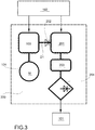
- the spinning textile machine 100 comprises a DC (Direct-current) power supply bus bar 101 (with a safe voltage level), schematically illustrated in the figure 1 with a block.
- DC Direct-current
- the DC power supply bus bar 101 is configured to provide a safe voltage level.
- the DC power supply bus bar 101 is configured to provide the electric components of spinning textile machine 100 with a DC power supply having the set electric safe voltage level, e.g. 24 V.
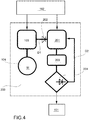
- the spinning textile machine 100 further comprises an electronic apparatus 200 arranged to electrically connect the DC power supply bus bar 101 to a AC power supply grid 102.
- the AC power supply grid 102 can be of the three phase type.
- the electronic apparatus 200 is arranged to provide the spinning textile machine 100 with AC (alternating-current) backup power supply also in the case of an outage of AC power supply provided by the AC power supply grid 102.
- the electronic apparatus 200 is configured to simply provide the spinning textile machine 100 with the AC power supply as provided by the AC power supply grid.
- the spinning textile machine 100 further comprises a plurality of frequency inverter modules 103 electrically connected to the AC power supply grid 102.
- Each of the frequency inverter module 103 is a frequency inverter for AC drives.
- the spinning textile machine 100 further comprises a plurality of sources of kinetic energy 104.
- Each source of kinetic energy, indicated also with the reference M, of said plurality of sources of kinetic energy 104 is electrically connected to a relative frequency inverter module 103 of said plurality of frequency inverter modules 103.
- each source of kinetic energy M of the plurality of sources of kinetic energy 104 is power supplied by the AC power supply grid via the relative frequency inverter module 103 of the plurality of frequency inverter module 103.
- the electronic apparatus 200 comprises a first frequency inverter module 103 of said plurality of frequency inverter modules 103.
- the first inverter module 103 can be a frequency inverter for AC drives.
- the electronic apparatus 200 comprises a source of kinetic energy M of said plurality of sources of kinetic energy 104.
- the source of kinetic energy M is electrically connected to the first frequency inverter module 103.
- the source of kinetic energy M is power supplied by the AC electric power grid 102 via the first frequency inverter module 103.
- the electronic apparatus 200 further comprises a second frequency inverter module 201 electrically connected to the first frequency inverter module 103 via a first DC electrical link D1 comprising a first diode 202.
- the second frequency inverter module 201 is power supplied by the first frequency inverter module 103 via the first DC electrical link D1 comprising the first diode 202.
- the first diode 202 of the first DC electrical link D1 is configured to advantageously allow the transferring of DC power supply from the first frequency inverter module 103 to the second frequency inverter module 202 and to avoid the transferring of DC power supply from the second frequency inverter module 202 to the first frequency inverter module 103.
- the electronic apparatus 200 further comprises a transformer module 203 and a rectifier module 204.
- the transformer module 203 is electrically connected to the DC power supply bus bar 101 via the rectifier module 204.
- the second frequency inverter module 201 is electrically connected to the DC power supply bus bar 101 via the transformer module 203 and the rectifier module 204.
- the first frequency inverter module 103 is advantageously configured, in the case of an outage of the AC power supply provided by the AC power supply grid 102, to detect an outage of the AC power supply provided by the AC power supply grid 102.
- the first frequency inverter module 103 is advantageously configured to receive a kinetic energy generated by the source of kinetic energy M as a AC backup power supply.
- the first frequency inverter module 103 is advantageously power supplied by the kinetic energy received by the source of kinetic energy M.
- the source of kinetic energy M in the case of an outage of the AC power supply, is configured to produce kinetic energy until the source of kinetic energy M stops and the deceleration is null.
- the first frequency inverter module 103 is advantageously configured provide, via the first DC electrical link D1 comprising the first diode 202, the second frequency inverter module 201 with the AC backup power supply received from the source of kinetic energy M.
- the second frequency inverter module 201 is advantageously power supplied by the kinetic energy generated by the source of kinetic energy M.
- the first frequency inverter module 103 is configured to switch into an AC backup power supply generator mode.
- the first frequency inverter module 103 is further configured to provide the second frequency inverter module 201 of the electronic apparatus 200 with a DC power supply also in the case of no outage of the AC power supply, via the first DC electrical link D1 comprising the first diode 202, during the normal operation of the spinning textile machine 100.
- the second frequency inverter module 201 of the electronic apparatus 200 is electrically connected to the AC power supply grid 102.
- the second frequency inverter module 201 of the electronic apparatus 200 is power supplied by the AC power supply grid 102 during the normal operation of the spinning textile machine 100.
- the electronic apparatus 200 comprises a second feedback DC electrical link D2.
- the rectifier 204 is electrically connected to the second frequency inverter module 201 via the feedback DC electrical link D2.
- the feedback DC electrical link D2 advantageously allows to provide the second frequency inverter module 201 with information representative of the real output voltage level of the DC power supply to be provided to the DC power supply bus bar 101 on the basis of the real load. In fact, the control of the output voltage level of the DC power supply depends on the load.
- the second frequency inverter module 201 can be configured to generate a correction of the output voltage level of the DC power supply and the frequency of the transformer module 203 (primary winding).
- the advantages of this embodiment are then to define and control the output voltage level of the DC power supply to be provided to the DC power supply bus bar 101 and, in case of the overvoltage from the AC power grid 102, to guarantee a safe output voltage level.
- the first frequency inverter module 103 is of the three phase type.
- the second frequency inverter module 201 is of the three phase type.
- each of the frequency inverter module of the plurality of frequency inverter modules 103 is of the three phase type.
- the source of kinetic energy M electrically connected to the first frequency inverter module 103 is one of a motor drive, a fan drive, a rotary machine drive.
- the spinning textile machine 100 further comprises a data processing unit 105, e.g. industrial PC, a power panel, a PLC, a microprocessor or a microcontroller, having a relative memory unit, electrically connected to the DC power supply bus bar 101 via a second diode 106.
- a data processing unit 105 e.g. industrial PC, a power panel, a PLC, a microprocessor or a microcontroller, having a relative memory unit, electrically connected to the DC power supply bus bar 101 via a second diode 106.
- the second diode 106 advantageously avoids the transferring of power energy from the power supply source 109 to the DC power supply bus bar 101.
- the data processing unit 105 is configured to control the operation of the spinning textile machine 100.
- the data processing unit 105 is configured to control the plurality of frequency inverter module 103, e.g. it is configured to control the start function and the stop function of each frequency inverter module.
- the data processing unit 105 is not configured to control the AC power supply of the spinning textile machine 100, with the exception of the case in which an emergency stop is required.
- the data processing unit 105 is configured to send safety electrical signal to the plurality of frequency inverter modules 103 to deadlock of output of each frequency inverter module to prevent movement of the drives.
- the first frequency inverter module 103 is configured to generate an electric signal representative of the detected outage of AC power supply.
- the first frequency inverter module 103 is further configured to provide the data processing unit 105 with said electrical signal representative of the detected outage of AC power supply.
- the spinning textile machine further comprises a plurality of electronic boards 107 electrically connected to the DC power supply bus bar 101.
- the plurality of electronic boards 107 may comprise a spinning position board or section board comprising a plurality of inputs and outputs to control electromechanical elements as electromagnets, electromagnetic valves and so on and to read input values from induction sensors, magnetic Hall sensors and so on.
- the plurality of electronic boards 107 may comprise driver boards for stepping motors, yarn breakage sensor, sensors of yarn cleaner, cleaner electronic boards and so on.
- Other electronic boards can be comprised in the plurality of electronic boards 107, configured to execute several functions, e.g. sliver feeding by stepping motor, arm lifting, damping, arm releasing, quality controlling the quality of the yarn and so on.
- the spinning textile machine 100 further comprises a plurality of stepping motor drives 108 electrically connected to the plurality of electronic boards 107.
- a stepping motor drive can be a drive for sliver feeding, where the speed and direction of the movement is controlled in dependence of the desired yarn fineness and the twist of the yarn.
- control electrical signals of a stepping motor drive are adjusted for the process of the joining to optimize the quality of the joining area.
- the spinning textile machine 100 further comprises a DC/DC converter 109 electrically connected between the first DC electrical link D1, upstream the first diode 202, and the data processing unit 105.
- a third diode 110 is arranged between the DC/DC converter 109 and the data processing unit 105.
- the third diode 110 advantageously protects the output of the DC/DC converter 109 against reverse polarity.
- the third diode 110 may be integrated in the DC/DC converter 109.
- an additional output protection for the DC/DC converter 109 can be provided.
- the DC/DC converter 109 is configured to provide the data processing unit 105 with power supply to be provided to electric/electronic circuits of safety relays (not shows in the figures) and also to control relays (not shown in the figures) to be used in the case of the failure of second frequency inverter module 201.
- a method for providing a spinning textile machine 100 with an AC backup power supply in the case of an outage of AC power supply is provided.
- the spinning textile machine 100 comprises an electronic apparatus 200 arranged to electrically connect a DC power supply bus bar 101 of the spinning textile machine 100 to a AC power supply grid 102.
- the electronic apparatus 200 comprises:
- the method comprises a step of recognizing, by the first frequency inverter module 103, the outage of the AC power supply by the AC power supply grid 102.
- the method further comprises the step of receiving, by the first frequency inverter module 103, the kinetic power energy generated by the source of kinetic energy M as a AC backup power supply.
- the method comprises the step of providing via the first DC electrical link D1 comprising the first diode 202, by the first frequency inverter module 103, the second frequency inverter module 201 with the AC backup power supply received from the source of kinetic energy M.
- the plurality of frequency inverter module 103 is power supplied by the AC power supply grid 102.
- the data processing unit 105 sends information to the plurality of frequency inverter module 103 in order to begin the process of textile manufacturing to be performed by the spinning textile machine 100.
- Each source of kinetic energy of said plurality of sources of kinetic energy 104 (drive motors, fan motors or rotary machine motors) operates on the basis of set parameters.
- the transformer 203 with the rectifier module 204 of the electronic apparatus 200 converts the AC power supply received by the AC power supply grid 102 into DC power supply to be provided to the DC power supply bus bar 101, then to the electronic components of the spinning textile machine 100, i.e. the data processing unit 105, the plurality of electronic boards 107, the plurality of stepping motor drives 108, and plurality of sensors (not shown in the figures).
- sensors are: induction sensors, magnetic Hall sensors, under-pressure sensors, yarn breakage sensors, yarn cleaner sensors and so on.
- the first frequency inverter module 103 detect the outage of AC power supply and switches into a generator mode, as previously explained.
- the source of kinetic energy M during deceleration after the outage of the AC power supply, provides the first frequency inverter module 103 with kinetic energy as AC backup power supply.
- the first frequency inverter module 103 provides the second frequency inverter module 201 with the AC backup power supply received from the source of kinetic energy M, via the first DC electrical link D1 comprising the first diode 202.
- the first diode 202 avoids the transferring of energy from the second frequency inverter module 201 to the first frequency inverter module 103.
- the kinetic energy as AC backup power supply continues to be generated by the source of kinetic energy M until the source of kinetic energy M completely stops.
- the electronic components of the spinning textile machine 100 need only about 10s to control the stop.
- the process keeps the yarn count and twist of the yarn same.
- the controlled stop saves start up time of the next startup of the spinning textile machine and therefore saves costs in the textile manufacturing performed by the spinning textile machine 100.
- the ends of the yarn, prepared inside the spinning units are able (with using adjusted start parameters for drives and sliver feeding) to join the end of the yarn to the spinning process.
- the spinning textile machine according to the present invention has several advantages.
- the spinning textile machine is simple.
- a frequency inverter module for AC drives is used as a source for primary winding of the transformer module, then the rectifier bridge is connected directly via fuses to DC bus.
- the spinning textile machine is functional.
- the recovery is provided by frequency inverter modules which integrate functions, transformer module and rectifier module which are basic and simple components with clear functionality.
- the spinning textile machine is reliable.
- the frequency inverter modules are suitable to be used in 3 phase industrial applications with long life in industrial environment.
- the transformer module and the rectifier module are not so critical components and while maintaining the operating conditions is also suitable for long life in operation.
- the spinning textile machine is saving costs because the recovery of the energy during deceleration is obtained and the short-term outage does not cause stop of the production of the spinning textile machine.
- a permanent outage stops machines in order and in state for fast start and fast recovery of production.
Landscapes
- Engineering & Computer Science (AREA)
- Mechanical Engineering (AREA)
- Textile Engineering (AREA)
- Business, Economics & Management (AREA)
- Emergency Management (AREA)
- Power Engineering (AREA)
- Spinning Or Twisting Of Yarns (AREA)
Claims (13)
- Spinntextilmaschine (100), umfassend:- eine DC-Stromversorgungssammelschiene (101);- eine elektronische Vorrichtung (200), die angeordnet ist, um die DC-Stromversorgungssammelschiene (101) elektrisch mit einem AC-Stromversorgungsnetz (102) zu verbinden, wobei die elektronische Vorrichtung (200) angeordnet ist, um die Spinntextilmaschine (100) mit AC-Reservestromzufuhr auch in dem Fall eines Ausfalls der vom AC-Stromversorgungsnetz (102) bereitgestellten AC-Stromversorgung zu versorgen;- eine Mehrzahl von Frequenzumrichtermodulen (103), die elektrisch mit dem AC-Stromversorgungsnetz (102) verbunden sind;- eine Mehrzahl von Quellen kinetischer Energie (104, M), wobei jede Quelle kinetischer Energie (M) der Mehrzahl von Quellen kinetischer Energie (104, M) elektrisch mit einem relativen Umrichtermodul (103) der Mehrzahl von Frequenzumrichtermodulen (103) verbunden ist;wobei die elektronische Vorrichtung (200) umfasst:- ein erstes Frequenzumrichtermodul (103) der Mehrzahl von Frequenzumrichtermodulen (103);- eine Quelle kinetischer Energie (M) der Mehrzahl von Quellen kinetischer Energie (104, M), wobei die Quelle kinetischer Energie (M) elektrisch mit dem ersten Frequenzumrichtermodul (103) verbunden ist und die Quelle kinetischer Energie (M) von dem AC-Stromversorgungsnetz (102) über das erste Frequenzumrichtermodul (103) mit Strom versorgt wird;dadurch gekennzeichnet, dass die elektronische Vorrichtung (200) ferner umfasst:- ein zweites Frequenzumrichtermodul (201), das elektrisch mit dem ersten Frequenzumrichtermodul (103) über eine erste elektrische DC-Verbindung (D1) verbunden ist, die eine erste Diode (202) umfasst, wobei das zweite Frequenzumrichtermodul (201) von dem ersten Frequenzumrichtermodul (103) über die erste elektrische DC-Verbindung (D1), welche die erste Diode (202) umfasst, mit Strom versorgt wird;- ein Transformatormodul (203) und ein Gleichrichtermodul (204), wobei das Transformatormodul (203) über das Gleichrichtermodul (204) mit der DC-Stromversorgungssammelschiene (101) elektrisch verbunden ist, wobei das zweite Frequenzumrichtermodul (201) über das Transformatormodul (203) und das Gleichrichtermodul (204) mit der DC-Stromversorgungssammelschiene (101) elektrisch verbunden ist,wobei in dem Falle eines Ausfalls der AC-Stromversorgung, die durch das AC-Stromversorgungsnetz (102) bereitgestellt wird, das erste Frequenzumrichtermodul (103) konfiguriert ist zum:- Erkennen eines Ausfalls der AC-Stromversorgung durch das AC-Stromversorgungsnetz (102);- Empfangen einer kinematische Energie, die von der Quelle kinetischer Energie (M) erzeugt wird, als eine AC-Reservestromzufuhr;- Versorgen, über die erste elektrische DC-Verbindung (D1), welche die erste Diode (202) umfasst, des zweiten Frequenzumrichtermoduls (201) mit der AC-Reservestromzufuhr, die von der Quelle kinetischer Energie (M) empfangen wird.
- Spinntextilmaschine (100) nach Anspruch 1, wobei das erste Frequenzumrichtermodul (103) ferner konfiguriert ist, das zweite Frequenzumrichtermodul (201) der elektronischen Vorrichtung (200) mit einer DC-Stromversorgung auch in dem Fall keines Ausfalls der AC-Stromversorgung über die erste elektrische DC-Verbindung (D1), welche die erste Diode (202) umfasst, während des normalen Betriebs der Spinntextilmaschine (100) zu versorgen.
- Spinntextilmaschine (100) nach Anspruch 1, wobei das zweite Frequenzumrichtermodul (201) der elektronischen Vorrichtung (200) mit dem AC-Stromversorgungsnetz (102) elektrisch verbunden ist, wobei das zweite Frequenzumrichtermodul (201) der elektronischen Vorrichtung (200) während des normalen Betriebs der Spinntextilmaschine (100) von dem AC-Stromversorgungsnetz (102) elektrisch versorgt wird.
- Spinntextilmaschine (100) nach einem der vorhergehenden Ansprüche, wobei die elektronische Vorrichtung (200) eine zweite elektrische Rückkopplungs-DC-Verbindung (D2) umfasst, wobei das Gleichrichtermodul (204) elektrisch mit dem zweiten Frequenzumrichtermodul (201) über die zweite elektrische Rückkopplungs-DC-Verbindung (D2) verbunden ist.
- Spinntextilmaschine (100) nach einem der vorhergehenden Ansprüche, wobei das erste Frequenzumrichtermodul (103) vom Dreiphasentyp ist.
- Spinntextilmaschine (100) nach einem der vorhergehenden Ansprüche, wobei das zweite Frequenzumrichtermodul (201) vom Dreiphasentyp ist.
- Spinntextilmaschine (100) nach einem der vorhergehenden Ansprüche, wobei jedes der Frequenzumrichtermodule der Mehrzahl von Frequenzumrichtermodulen (103) vom Dreiphasentyp ist.
- Spinntextilmaschine (100) nach einem der vorhergehenden Ansprüche, wobei die Quelle kinetischer Energie (M), die mit dem ersten Frequenzumrichtermodul (103) elektrisch verbunden ist, eine eines Motorantriebs, eines Lüfterantriebs oder eines Rotationsmaschinenantriebs ist.
- Spinntextilmaschine (100) nach einem der vorhergehenden Ansprüche, ferner umfassend eine Datenverarbeitungseinheit (105), die elektrisch mit der DC-Stromsversorgungssammelschiene (101) verbunden ist, wobei die Datenverarbeitungseinheit (105) konfiguriert ist, den Betrieb der Spinntextilmaschine (100) zu steuern bzw. zu regeln.
- Spinntextilmaschine (100) nach Anspruch 9, wobei das erste Frequenzumrichtermodul (103) konfiguriert ist, ein elektrisches Signal zu erzeugen, das den erfassten Ausfall der AC-Stromversorgung darstellt, wobei das erste Frequenzumrichtermodul (103) konfiguriert ist, die Datenverarbeitungseinheit (105) mit dem elektrischen Signal zu versorgen, das den erfassten Ausfall der Stromversorgung darstellt.
- Spinntextilmaschine (100) nach einem der vorhergehenden Ansprüche, ferner umfassend eine Mehrzahl von elektronischen Platinen (107), die elektrisch mit der DC-Stromversorgungssammelschiene (101) verbunden sind.
- Spinntextilmaschine (100) nach Anspruch 11, ferner umfassend eine Mehrzahl von Schrittmotorantrieben (108), die elektrisch mit der Mehrzahl elektronischer Platinen (107) verbunden sind.
- Verfahren zum Versorgen einer Spinntextilmaschine (100) mit einer AC-Reservestromzufuhr in dem Fall eines Ausfalls der AC-Stromversorgung, wobei die Spinntextilmaschine (100) eine elektronische Vorrichtung (200) umfasst, die angeordnet ist, um eine DC-Stromversorgungssammelschiene (101) der Spinntextilmaschine (100) elektrisch mit einem AC-Stromversorgungsnetz (102) zu verbinden,
wobei die elektronische Vorrichtung (200) umfasst:- ein erstes Frequenzumrichtermodul (103) einer Mehrzahl von Frequenzumrichtermodulen (103) der Spinntextilmaschine (100);- eine Quelle kinetischer Energie (M) einer Mehrzahl von Quellen kinetischer Energie (104, M) der Spinntextilmaschine (100), wobei die Quelle kinetischer Energie (M) elektrisch mit dem ersten Frequenzumrichtermodul (103) verbunden ist, wobei die Quelle kinetischer Energie (M) von dem AC-Stromversorgungsnetz (102) über das erste Frequenzumrichtermodul (103) mit Strom versorgt wird;dadurch gekennzeichnet, dass die elektronische Vorrichtung (200) ferner umfasst:- ein zweites Frequenzumrichtermodul (201), das elektrisch mit dem ersten Frequenzumrichtermodul (103) über eine erste elektrische DC-Verbindung (D1) verbunden ist, die eine erste Diode (202) aufweist, wobei das zweite Frequenzumrichtermodul (201) von dem ersten Frequenzumrichtermodul (103) über die erste elektrische DC-Verbindung (D1), welche die erste Diode (202) aufweist, mit Strom versorgt wird;- ein Transformatormodul (203) und ein Gleichrichtermodul (204), wobei das Transformatormodul (203) über das Gleichrichtermodul (204) mit der DC-Stromversorgungssammelschiene (101) elektrisch verbunden ist, wobei das zweite Frequenzumrichtermodul (201) über das Transformatormodul (203) und das Gleichrichtermodul (204) mit der DC-Stromversorgungssammelschiene (101) elektrisch verbunden ist,wobei in dem Falle eines Ausfalls der AC-Stromversorgung das Verfahren die Schritte umfasst:- Erkennen, durch das erste Frequenzumrichtermodul (103), des Ausfalls der AC-Stromversorgung, die durch das AC-Stromversorgungsnetz (102) bereitgestellt wird;- Empfangen, durch das erste Frequenzumrichtermodul (103), der kinematischen Energie, die von der Quelle kinetischer Energie (M) erzeugt wird;- Versorgen, durch das erste Frequenzumrichtermodul (103) über die erste elektrische DC-Verbindung (D1), welche die erste Diode (202) aufweist, des zweiten Frequenzumrichtermoduls (201) mit der AC-Reservestromzufuhr, die von der Quelle kinetischer Energie (M) empfangen wird.
Applications Claiming Priority (1)
| Application Number | Priority Date | Filing Date | Title |
|---|---|---|---|
| IT102017000010272A IT201700010272A1 (it) | 2017-01-31 | 2017-01-31 | Macchina tessile di filatura con apparato elettronico per fornire alla macchina tessile di filatura un'alimentazione elettrica ac di backup in caso di interruzione dell'alimentazione elettrica ac |
Publications (2)
| Publication Number | Publication Date |
|---|---|
| EP3354775A1 EP3354775A1 (de) | 2018-08-01 |
| EP3354775B1 true EP3354775B1 (de) | 2019-11-27 |
Family
ID=58779315
Family Applications (1)
| Application Number | Title | Priority Date | Filing Date |
|---|---|---|---|
| EP18153522.0A Active EP3354775B1 (de) | 2017-01-31 | 2018-01-25 | Spinnmaschine mit elektronischem gerät zur verfügung der spinnmaschine mit ac-backup-stromversorgung im fall eines ausgangs der stromversorgung |
Country Status (3)
| Country | Link |
|---|---|
| EP (1) | EP3354775B1 (de) |
| CN (2) | CN208046304U (de) |
| IT (1) | IT201700010272A1 (de) |
Families Citing this family (6)
| Publication number | Priority date | Publication date | Assignee | Title |
|---|---|---|---|---|
| IT201700010272A1 (it) * | 2017-01-31 | 2018-07-31 | Savio Macch Tessili Spa | Macchina tessile di filatura con apparato elettronico per fornire alla macchina tessile di filatura un'alimentazione elettrica ac di backup in caso di interruzione dell'alimentazione elettrica ac |
| DE102020117904A1 (de) * | 2019-07-16 | 2021-01-21 | Oerlikon Textile Gmbh & Co. Kg | Förderwerk zum Rückgewinnen eines Teils der Antriebsenergie |
| CN110932387A (zh) * | 2019-12-27 | 2020-03-27 | 安徽日发纺织机械有限公司 | 一种转杯纺纱机断电不停机方法以及应用该方法的装置 |
| CN111614246A (zh) * | 2020-05-29 | 2020-09-01 | 卓郎(江苏)纺织机械有限公司 | 具有安全直流输出停止功能的整流器、驱动电路及系统 |
| CN111555439A (zh) * | 2020-05-29 | 2020-08-18 | 卓郎(江苏)纺织机械有限公司 | 一种具有不间断直流输出的整流器 |
| EP3961898B1 (de) * | 2020-08-31 | 2023-01-25 | Maschinenfabrik Rieter AG | Spinnmaschine |
Family Cites Families (5)
| Publication number | Priority date | Publication date | Assignee | Title |
|---|---|---|---|---|
| JPH0544118A (ja) * | 1991-07-31 | 1993-02-23 | Howa Mach Ltd | 粗紡機における制御装置 |
| JP2000078870A (ja) * | 1998-08-31 | 2000-03-14 | Murata Mach Ltd | モータ駆動システム |
| JP3791511B2 (ja) * | 2003-05-21 | 2006-06-28 | 村田機械株式会社 | 紡績機における駆動制御システム |
| FR2867786B1 (fr) * | 2004-03-22 | 2006-05-12 | Rieter Textile Machinery Fr | Dispositif de gestion d'une coupure d'alimentation electrique dans une machine textile notamment de transformation de fils |
| IT201700010272A1 (it) * | 2017-01-31 | 2018-07-31 | Savio Macch Tessili Spa | Macchina tessile di filatura con apparato elettronico per fornire alla macchina tessile di filatura un'alimentazione elettrica ac di backup in caso di interruzione dell'alimentazione elettrica ac |
-
2017
- 2017-01-31 IT IT102017000010272A patent/IT201700010272A1/it unknown
-
2018
- 2018-01-25 EP EP18153522.0A patent/EP3354775B1/de active Active
- 2018-01-30 CN CN201820161982.6U patent/CN208046304U/zh not_active Withdrawn - After Issue
- 2018-01-30 CN CN201810091658.6A patent/CN108377028B/zh not_active Expired - Fee Related
Non-Patent Citations (1)
| Title |
|---|
| None * |
Also Published As
| Publication number | Publication date |
|---|---|
| CN208046304U (zh) | 2018-11-02 |
| IT201700010272A1 (it) | 2018-07-31 |
| CN108377028A (zh) | 2018-08-07 |
| EP3354775A1 (de) | 2018-08-01 |
| CN108377028B (zh) | 2023-06-20 |
Similar Documents
| Publication | Publication Date | Title |
|---|---|---|
| EP3354775A1 (de) | Spinnmaschine mit elektronischem gerät zur verfügung der spinnmaschine mit ac-backup-stromversorgung im fall eines ausgangs der stromversorgung | |
| JP5722400B2 (ja) | 主軸を有する工作機械の制御装置 | |
| CN101427456A (zh) | 电机用驱动系统 | |
| EP3406344B1 (de) | Stoppverfahren und -vorrichtung für zentrifugalmaschine mit magnetischer aufhängung | |
| US7928620B2 (en) | Device for safeguarding an uninterruptible power supply of a magnet bearing in the event of failure of an electrical supply voltage | |
| CN108450051B (zh) | 用于工业机器人的电驱动器 | |
| JP4264906B2 (ja) | 誘導電動機駆動装置 | |
| KR20210130811A (ko) | 전동모터용의 제어장치 및 이를 구비한 로봇, 및 전동모터의 제어방법 | |
| JP6533548B2 (ja) | 乗客コンベア | |
| EP3090841A1 (de) | Robotersteuerungssystem | |
| CN111082415A (zh) | 电梯系统中的功率源失效期间对ac负载的功率供应 | |
| EP3640488B1 (de) | Stromversorgungssystem für magnetlager und steuerverfahren dafür | |
| JP5225314B2 (ja) | モータ制御装置とその故障検出方法 | |
| EP3822789B1 (de) | Funktionales sicherheitssoftwarekonzept für motorantriebe | |
| EP3633465B1 (de) | Diagnosevorrichtung | |
| CN108347213A (zh) | 电动机驱动装置 | |
| KR20000017626A (ko) | 모터구동시스템 | |
| US20120169051A1 (en) | Emergency Adjustment Device for Blade Pitch Adjustment Systems for Wind Energy Installations | |
| JP2017195734A (ja) | 交流回転機の制御装置及び制御方法 | |
| JP5383028B2 (ja) | 紡績機および紡績機の駆動方法 | |
| CN111033997A (zh) | 电力供给装置 | |
| JPH10243675A (ja) | モータ停止回路 | |
| RU2540959C2 (ru) | Электропривод переменного тока повышенной живучести | |
| CN110794769B (zh) | 用于防止意外断电造成断纱的送纱伺服装置 | |
| CN203339672U (zh) | 一种具有过电压保护功能的低压变频器 |
Legal Events
| Date | Code | Title | Description |
|---|---|---|---|
| PUAI | Public reference made under article 153(3) epc to a published international application that has entered the european phase |
Free format text: ORIGINAL CODE: 0009012 |
|
| STAA | Information on the status of an ep patent application or granted ep patent |
Free format text: STATUS: THE APPLICATION HAS BEEN PUBLISHED |
|
| AK | Designated contracting states |
Kind code of ref document: A1 Designated state(s): AL AT BE BG CH CY CZ DE DK EE ES FI FR GB GR HR HU IE IS IT LI LT LU LV MC MK MT NL NO PL PT RO RS SE SI SK SM TR |
|
| AX | Request for extension of the european patent |
Extension state: BA ME |
|
| STAA | Information on the status of an ep patent application or granted ep patent |
Free format text: STATUS: REQUEST FOR EXAMINATION WAS MADE |
|
| 17P | Request for examination filed |
Effective date: 20190117 |
|
| RBV | Designated contracting states (corrected) |
Designated state(s): AL AT BE BG CH CY CZ DE DK EE ES FI FR GB GR HR HU IE IS IT LI LT LU LV MC MK MT NL NO PL PT RO RS SE SI SK SM TR |
|
| GRAP | Despatch of communication of intention to grant a patent |
Free format text: ORIGINAL CODE: EPIDOSNIGR1 |
|
| STAA | Information on the status of an ep patent application or granted ep patent |
Free format text: STATUS: GRANT OF PATENT IS INTENDED |
|
| INTG | Intention to grant announced |
Effective date: 20190628 |
|
| GRAS | Grant fee paid |
Free format text: ORIGINAL CODE: EPIDOSNIGR3 |
|
| GRAA | (expected) grant |
Free format text: ORIGINAL CODE: 0009210 |
|
| STAA | Information on the status of an ep patent application or granted ep patent |
Free format text: STATUS: THE PATENT HAS BEEN GRANTED |
|
| AK | Designated contracting states |
Kind code of ref document: B1 Designated state(s): AL AT BE BG CH CY CZ DE DK EE ES FI FR GB GR HR HU IE IS IT LI LT LU LV MC MK MT NL NO PL PT RO RS SE SI SK SM TR |
|
| REG | Reference to a national code |
Ref country code: GB Ref legal event code: FG4D |
|
| REG | Reference to a national code |
Ref country code: CH Ref legal event code: EP |
|
| REG | Reference to a national code |
Ref country code: AT Ref legal event code: REF Ref document number: 1206752 Country of ref document: AT Kind code of ref document: T Effective date: 20191215 |
|
| REG | Reference to a national code |
Ref country code: DE Ref legal event code: R096 Ref document number: 602018001309 Country of ref document: DE |
|
| REG | Reference to a national code |
Ref country code: IE Ref legal event code: FG4D |
|
| REG | Reference to a national code |
Ref country code: CH Ref legal event code: NV Representative=s name: VALIPAT S.A. C/O BOVARD SA NEUCHATEL, CH |
|
| REG | Reference to a national code |
Ref country code: NL Ref legal event code: MP Effective date: 20191127 |
|
| REG | Reference to a national code |
Ref country code: LT Ref legal event code: MG4D |
|
| PG25 | Lapsed in a contracting state [announced via postgrant information from national office to epo] |
Ref country code: NL Free format text: LAPSE BECAUSE OF FAILURE TO SUBMIT A TRANSLATION OF THE DESCRIPTION OR TO PAY THE FEE WITHIN THE PRESCRIBED TIME-LIMIT Effective date: 20191127 Ref country code: LT Free format text: LAPSE BECAUSE OF FAILURE TO SUBMIT A TRANSLATION OF THE DESCRIPTION OR TO PAY THE FEE WITHIN THE PRESCRIBED TIME-LIMIT Effective date: 20191127 Ref country code: NO Free format text: LAPSE BECAUSE OF FAILURE TO SUBMIT A TRANSLATION OF THE DESCRIPTION OR TO PAY THE FEE WITHIN THE PRESCRIBED TIME-LIMIT Effective date: 20200227 Ref country code: BG Free format text: LAPSE BECAUSE OF FAILURE TO SUBMIT A TRANSLATION OF THE DESCRIPTION OR TO PAY THE FEE WITHIN THE PRESCRIBED TIME-LIMIT Effective date: 20200227 Ref country code: GR Free format text: LAPSE BECAUSE OF FAILURE TO SUBMIT A TRANSLATION OF THE DESCRIPTION OR TO PAY THE FEE WITHIN THE PRESCRIBED TIME-LIMIT Effective date: 20200228 Ref country code: FI Free format text: LAPSE BECAUSE OF FAILURE TO SUBMIT A TRANSLATION OF THE DESCRIPTION OR TO PAY THE FEE WITHIN THE PRESCRIBED TIME-LIMIT Effective date: 20191127 Ref country code: SE Free format text: LAPSE BECAUSE OF FAILURE TO SUBMIT A TRANSLATION OF THE DESCRIPTION OR TO PAY THE FEE WITHIN THE PRESCRIBED TIME-LIMIT Effective date: 20191127 Ref country code: LV Free format text: LAPSE BECAUSE OF FAILURE TO SUBMIT A TRANSLATION OF THE DESCRIPTION OR TO PAY THE FEE WITHIN THE PRESCRIBED TIME-LIMIT Effective date: 20191127 |
|
| PG25 | Lapsed in a contracting state [announced via postgrant information from national office to epo] |
Ref country code: RS Free format text: LAPSE BECAUSE OF FAILURE TO SUBMIT A TRANSLATION OF THE DESCRIPTION OR TO PAY THE FEE WITHIN THE PRESCRIBED TIME-LIMIT Effective date: 20191127 Ref country code: IS Free format text: LAPSE BECAUSE OF FAILURE TO SUBMIT A TRANSLATION OF THE DESCRIPTION OR TO PAY THE FEE WITHIN THE PRESCRIBED TIME-LIMIT Effective date: 20200327 Ref country code: HR Free format text: LAPSE BECAUSE OF FAILURE TO SUBMIT A TRANSLATION OF THE DESCRIPTION OR TO PAY THE FEE WITHIN THE PRESCRIBED TIME-LIMIT Effective date: 20191127 |
|
| PG25 | Lapsed in a contracting state [announced via postgrant information from national office to epo] |
Ref country code: AL Free format text: LAPSE BECAUSE OF FAILURE TO SUBMIT A TRANSLATION OF THE DESCRIPTION OR TO PAY THE FEE WITHIN THE PRESCRIBED TIME-LIMIT Effective date: 20191127 |
|
| PG25 | Lapsed in a contracting state [announced via postgrant information from national office to epo] |
Ref country code: ES Free format text: LAPSE BECAUSE OF FAILURE TO SUBMIT A TRANSLATION OF THE DESCRIPTION OR TO PAY THE FEE WITHIN THE PRESCRIBED TIME-LIMIT Effective date: 20191127 Ref country code: RO Free format text: LAPSE BECAUSE OF FAILURE TO SUBMIT A TRANSLATION OF THE DESCRIPTION OR TO PAY THE FEE WITHIN THE PRESCRIBED TIME-LIMIT Effective date: 20191127 Ref country code: DK Free format text: LAPSE BECAUSE OF FAILURE TO SUBMIT A TRANSLATION OF THE DESCRIPTION OR TO PAY THE FEE WITHIN THE PRESCRIBED TIME-LIMIT Effective date: 20191127 Ref country code: PT Free format text: LAPSE BECAUSE OF FAILURE TO SUBMIT A TRANSLATION OF THE DESCRIPTION OR TO PAY THE FEE WITHIN THE PRESCRIBED TIME-LIMIT Effective date: 20200419 Ref country code: EE Free format text: LAPSE BECAUSE OF FAILURE TO SUBMIT A TRANSLATION OF THE DESCRIPTION OR TO PAY THE FEE WITHIN THE PRESCRIBED TIME-LIMIT Effective date: 20191127 |
|
| REG | Reference to a national code |
Ref country code: DE Ref legal event code: R097 Ref document number: 602018001309 Country of ref document: DE |
|
| PG25 | Lapsed in a contracting state [announced via postgrant information from national office to epo] |
Ref country code: MC Free format text: LAPSE BECAUSE OF FAILURE TO SUBMIT A TRANSLATION OF THE DESCRIPTION OR TO PAY THE FEE WITHIN THE PRESCRIBED TIME-LIMIT Effective date: 20191127 Ref country code: SK Free format text: LAPSE BECAUSE OF FAILURE TO SUBMIT A TRANSLATION OF THE DESCRIPTION OR TO PAY THE FEE WITHIN THE PRESCRIBED TIME-LIMIT Effective date: 20191127 Ref country code: SM Free format text: LAPSE BECAUSE OF FAILURE TO SUBMIT A TRANSLATION OF THE DESCRIPTION OR TO PAY THE FEE WITHIN THE PRESCRIBED TIME-LIMIT Effective date: 20191127 |
|
| REG | Reference to a national code |
Ref country code: AT Ref legal event code: MK05 Ref document number: 1206752 Country of ref document: AT Kind code of ref document: T Effective date: 20191127 |
|
| PLBE | No opposition filed within time limit |
Free format text: ORIGINAL CODE: 0009261 |
|
| STAA | Information on the status of an ep patent application or granted ep patent |
Free format text: STATUS: NO OPPOSITION FILED WITHIN TIME LIMIT |
|
| REG | Reference to a national code |
Ref country code: BE Ref legal event code: MM Effective date: 20200131 |
|
| PG25 | Lapsed in a contracting state [announced via postgrant information from national office to epo] |
Ref country code: FR Free format text: LAPSE BECAUSE OF NON-PAYMENT OF DUE FEES Effective date: 20200127 Ref country code: LU Free format text: LAPSE BECAUSE OF NON-PAYMENT OF DUE FEES Effective date: 20200125 |
|
| 26N | No opposition filed |
Effective date: 20200828 |
|
| PG25 | Lapsed in a contracting state [announced via postgrant information from national office to epo] |
Ref country code: PL Free format text: LAPSE BECAUSE OF FAILURE TO SUBMIT A TRANSLATION OF THE DESCRIPTION OR TO PAY THE FEE WITHIN THE PRESCRIBED TIME-LIMIT Effective date: 20191127 Ref country code: BE Free format text: LAPSE BECAUSE OF NON-PAYMENT OF DUE FEES Effective date: 20200131 Ref country code: SI Free format text: LAPSE BECAUSE OF FAILURE TO SUBMIT A TRANSLATION OF THE DESCRIPTION OR TO PAY THE FEE WITHIN THE PRESCRIBED TIME-LIMIT Effective date: 20191127 Ref country code: AT Free format text: LAPSE BECAUSE OF FAILURE TO SUBMIT A TRANSLATION OF THE DESCRIPTION OR TO PAY THE FEE WITHIN THE PRESCRIBED TIME-LIMIT Effective date: 20191127 |
|
| PG25 | Lapsed in a contracting state [announced via postgrant information from national office to epo] |
Ref country code: IE Free format text: LAPSE BECAUSE OF NON-PAYMENT OF DUE FEES Effective date: 20200125 |
|
| PG25 | Lapsed in a contracting state [announced via postgrant information from national office to epo] |
Ref country code: MT Free format text: LAPSE BECAUSE OF FAILURE TO SUBMIT A TRANSLATION OF THE DESCRIPTION OR TO PAY THE FEE WITHIN THE PRESCRIBED TIME-LIMIT Effective date: 20191127 Ref country code: CY Free format text: LAPSE BECAUSE OF FAILURE TO SUBMIT A TRANSLATION OF THE DESCRIPTION OR TO PAY THE FEE WITHIN THE PRESCRIBED TIME-LIMIT Effective date: 20191127 |
|
| PG25 | Lapsed in a contracting state [announced via postgrant information from national office to epo] |
Ref country code: MK Free format text: LAPSE BECAUSE OF FAILURE TO SUBMIT A TRANSLATION OF THE DESCRIPTION OR TO PAY THE FEE WITHIN THE PRESCRIBED TIME-LIMIT Effective date: 20191127 |
|
| GBPC | Gb: european patent ceased through non-payment of renewal fee |
Effective date: 20220125 |
|
| PG25 | Lapsed in a contracting state [announced via postgrant information from national office to epo] |
Ref country code: GB Free format text: LAPSE BECAUSE OF NON-PAYMENT OF DUE FEES Effective date: 20220125 |
|
| P01 | Opt-out of the competence of the unified patent court (upc) registered |
Effective date: 20230526 |
|
| PGFP | Annual fee paid to national office [announced via postgrant information from national office to epo] |
Ref country code: CZ Payment date: 20231123 Year of fee payment: 7 |
|
| PGFP | Annual fee paid to national office [announced via postgrant information from national office to epo] |
Ref country code: DE Payment date: 20240119 Year of fee payment: 7 Ref country code: CH Payment date: 20240202 Year of fee payment: 7 |
|
| PGFP | Annual fee paid to national office [announced via postgrant information from national office to epo] |
Ref country code: TR Payment date: 20240122 Year of fee payment: 7 Ref country code: IT Payment date: 20231106 Year of fee payment: 7 |
|
| REG | Reference to a national code |
Ref country code: DE Ref legal event code: R119 Ref document number: 602018001309 Country of ref document: DE |
|
| REG | Reference to a national code |
Ref country code: CH Ref legal event code: PL |
|
| PG25 | Lapsed in a contracting state [announced via postgrant information from national office to epo] |
Ref country code: DE Free format text: LAPSE BECAUSE OF NON-PAYMENT OF DUE FEES Effective date: 20250801 |
|
| PG25 | Lapsed in a contracting state [announced via postgrant information from national office to epo] |
Ref country code: CH Free format text: LAPSE BECAUSE OF NON-PAYMENT OF DUE FEES Effective date: 20250131 |
|
| PG25 | Lapsed in a contracting state [announced via postgrant information from national office to epo] |
Ref country code: CZ Free format text: LAPSE BECAUSE OF NON-PAYMENT OF DUE FEES Effective date: 20250125 |
|
| PG25 | Lapsed in a contracting state [announced via postgrant information from national office to epo] |
Ref country code: IT Free format text: LAPSE BECAUSE OF NON-PAYMENT OF DUE FEES Effective date: 20250125 |