EP3640488B1 - Stromversorgungssystem für magnetlager und steuerverfahren dafür - Google Patents
Stromversorgungssystem für magnetlager und steuerverfahren dafür Download PDFInfo
- Publication number
- EP3640488B1 EP3640488B1 EP18875241.4A EP18875241A EP3640488B1 EP 3640488 B1 EP3640488 B1 EP 3640488B1 EP 18875241 A EP18875241 A EP 18875241A EP 3640488 B1 EP3640488 B1 EP 3640488B1
- Authority
- EP
- European Patent Office
- Prior art keywords
- power supply
- direct current
- power
- voltage
- electric motor
- Prior art date
- Legal status (The legal status is an assumption and is not a legal conclusion. Google has not performed a legal analysis and makes no representation as to the accuracy of the status listed.)
- Active
Links
Images

Classifications
-
- F—MECHANICAL ENGINEERING; LIGHTING; HEATING; WEAPONS; BLASTING
- F16—ENGINEERING ELEMENTS AND UNITS; GENERAL MEASURES FOR PRODUCING AND MAINTAINING EFFECTIVE FUNCTIONING OF MACHINES OR INSTALLATIONS; THERMAL INSULATION IN GENERAL
- F16C—SHAFTS; FLEXIBLE SHAFTS; ELEMENTS OR CRANKSHAFT MECHANISMS; ROTARY BODIES OTHER THAN GEARING ELEMENTS; BEARINGS
- F16C32/00—Bearings not otherwise provided for
- F16C32/04—Bearings not otherwise provided for using magnetic or electric supporting means
- F16C32/0406—Magnetic bearings
- F16C32/044—Active magnetic bearings
- F16C32/0442—Active magnetic bearings with devices affected by abnormal, undesired or non-standard conditions such as shock-load, power outage, start-up or touchdown
-
- F—MECHANICAL ENGINEERING; LIGHTING; HEATING; WEAPONS; BLASTING
- F16—ENGINEERING ELEMENTS AND UNITS; GENERAL MEASURES FOR PRODUCING AND MAINTAINING EFFECTIVE FUNCTIONING OF MACHINES OR INSTALLATIONS; THERMAL INSULATION IN GENERAL
- F16C—SHAFTS; FLEXIBLE SHAFTS; ELEMENTS OR CRANKSHAFT MECHANISMS; ROTARY BODIES OTHER THAN GEARING ELEMENTS; BEARINGS
- F16C32/00—Bearings not otherwise provided for
- F16C32/04—Bearings not otherwise provided for using magnetic or electric supporting means
- F16C32/0406—Magnetic bearings
- F16C32/044—Active magnetic bearings
- F16C32/0444—Details of devices to control the actuation of the electromagnets
- F16C32/0457—Details of the power supply to the electromagnets
-
- F—MECHANICAL ENGINEERING; LIGHTING; HEATING; WEAPONS; BLASTING
- F16—ENGINEERING ELEMENTS AND UNITS; GENERAL MEASURES FOR PRODUCING AND MAINTAINING EFFECTIVE FUNCTIONING OF MACHINES OR INSTALLATIONS; THERMAL INSULATION IN GENERAL
- F16C—SHAFTS; FLEXIBLE SHAFTS; ELEMENTS OR CRANKSHAFT MECHANISMS; ROTARY BODIES OTHER THAN GEARING ELEMENTS; BEARINGS
- F16C32/00—Bearings not otherwise provided for
- F16C32/04—Bearings not otherwise provided for using magnetic or electric supporting means
- F16C32/0406—Magnetic bearings
- F16C32/044—Active magnetic bearings
- F16C32/0444—Details of devices to control the actuation of the electromagnets
- F16C32/0451—Details of controllers, i.e. the units determining the power to be supplied, e.g. comparing elements, feedback arrangements with P.I.D. control
-
- H—ELECTRICITY
- H02—GENERATION; CONVERSION OR DISTRIBUTION OF ELECTRIC POWER
- H02K—DYNAMO-ELECTRIC MACHINES
- H02K7/00—Arrangements for handling mechanical energy structurally associated with dynamo-electric machines, e.g. structural association with mechanical driving motors or auxiliary dynamo-electric machines
- H02K7/08—Structural association with bearings
- H02K7/09—Structural association with bearings with magnetic bearings
-
- H—ELECTRICITY
- H02—GENERATION; CONVERSION OR DISTRIBUTION OF ELECTRIC POWER
- H02M—APPARATUS FOR CONVERSION BETWEEN AC AND AC, BETWEEN AC AND DC, OR BETWEEN DC AND DC, AND FOR USE WITH MAINS OR SIMILAR POWER SUPPLY SYSTEMS; CONVERSION OF DC OR AC INPUT POWER INTO SURGE OUTPUT POWER; CONTROL OR REGULATION THEREOF
- H02M1/00—Details of apparatus for conversion
-
- H—ELECTRICITY
- H02—GENERATION; CONVERSION OR DISTRIBUTION OF ELECTRIC POWER
- H02M—APPARATUS FOR CONVERSION BETWEEN AC AND AC, BETWEEN AC AND DC, OR BETWEEN DC AND DC, AND FOR USE WITH MAINS OR SIMILAR POWER SUPPLY SYSTEMS; CONVERSION OF DC OR AC INPUT POWER INTO SURGE OUTPUT POWER; CONTROL OR REGULATION THEREOF
- H02M1/00—Details of apparatus for conversion
- H02M1/36—Means for starting or stopping converters
-
- H—ELECTRICITY
- H02—GENERATION; CONVERSION OR DISTRIBUTION OF ELECTRIC POWER
- H02M—APPARATUS FOR CONVERSION BETWEEN AC AND AC, BETWEEN AC AND DC, OR BETWEEN DC AND DC, AND FOR USE WITH MAINS OR SIMILAR POWER SUPPLY SYSTEMS; CONVERSION OF DC OR AC INPUT POWER INTO SURGE OUTPUT POWER; CONTROL OR REGULATION THEREOF
- H02M3/00—Conversion of DC power input into DC power output
- H02M3/02—Conversion of DC power input into DC power output without intermediate conversion into AC
- H02M3/04—Conversion of DC power input into DC power output without intermediate conversion into AC by static converters
-
- H—ELECTRICITY
- H02—GENERATION; CONVERSION OR DISTRIBUTION OF ELECTRIC POWER
- H02M—APPARATUS FOR CONVERSION BETWEEN AC AND AC, BETWEEN AC AND DC, OR BETWEEN DC AND DC, AND FOR USE WITH MAINS OR SIMILAR POWER SUPPLY SYSTEMS; CONVERSION OF DC OR AC INPUT POWER INTO SURGE OUTPUT POWER; CONTROL OR REGULATION THEREOF
- H02M5/00—Conversion of AC power input into AC power output, e.g. for change of voltage, for change of frequency, for change of number of phases
- H02M5/40—Conversion of AC power input into AC power output, e.g. for change of voltage, for change of frequency, for change of number of phases with intermediate conversion into DC
- H02M5/42—Conversion of AC power input into AC power output, e.g. for change of voltage, for change of frequency, for change of number of phases with intermediate conversion into DC by static converters
- H02M5/44—Conversion of AC power input into AC power output, e.g. for change of voltage, for change of frequency, for change of number of phases with intermediate conversion into DC by static converters using discharge tubes or semiconductor devices to convert the intermediate DC into AC
- H02M5/453—Conversion of AC power input into AC power output, e.g. for change of voltage, for change of frequency, for change of number of phases with intermediate conversion into DC by static converters using discharge tubes or semiconductor devices to convert the intermediate DC into AC using devices of a triode or transistor type requiring continuous application of a control signal
- H02M5/458—Conversion of AC power input into AC power output, e.g. for change of voltage, for change of frequency, for change of number of phases with intermediate conversion into DC by static converters using discharge tubes or semiconductor devices to convert the intermediate DC into AC using devices of a triode or transistor type requiring continuous application of a control signal using semiconductor devices only
-
- H—ELECTRICITY
- H02—GENERATION; CONVERSION OR DISTRIBUTION OF ELECTRIC POWER
- H02N—ELECTRIC MACHINES NOT OTHERWISE PROVIDED FOR
- H02N15/00—Holding or levitation devices using magnetic attraction or repulsion, not otherwise provided for
-
- H—ELECTRICITY
- H02—GENERATION; CONVERSION OR DISTRIBUTION OF ELECTRIC POWER
- H02M—APPARATUS FOR CONVERSION BETWEEN AC AND AC, BETWEEN AC AND DC, OR BETWEEN DC AND DC, AND FOR USE WITH MAINS OR SIMILAR POWER SUPPLY SYSTEMS; CONVERSION OF DC OR AC INPUT POWER INTO SURGE OUTPUT POWER; CONTROL OR REGULATION THEREOF
- H02M1/00—Details of apparatus for conversion
- H02M1/0067—Converter structures employing plural converter units, other than for parallel operation of the units on a single load
- H02M1/007—Plural converter units in cascade
-
- H—ELECTRICITY
- H02—GENERATION; CONVERSION OR DISTRIBUTION OF ELECTRIC POWER
- H02M—APPARATUS FOR CONVERSION BETWEEN AC AND AC, BETWEEN AC AND DC, OR BETWEEN DC AND DC, AND FOR USE WITH MAINS OR SIMILAR POWER SUPPLY SYSTEMS; CONVERSION OF DC OR AC INPUT POWER INTO SURGE OUTPUT POWER; CONTROL OR REGULATION THEREOF
- H02M1/00—Details of apparatus for conversion
- H02M1/0083—Converters characterised by their input or output configuration
- H02M1/009—Converters characterised by their input or output configuration having two or more independently controlled outputs
Definitions
- the present invention relates to the technical field of electric motor, and particularly to a power supply system for a magnetic bearing and a control method therefor.
- a magnetic bearing makes a rotor (i.e., shaft) of an electric motor suspend in the air by magnetic force effect and is not in mechanical contact with a stator of the electric motor.
- a rotor i.e., shaft
- one of the most critical problems to be solved is how to maintain the suspension of the rotor until the rotor stops rotating in a case of sudden power off during high-speed running of the electric motor.
- the low voltage power supply of a bearing controller is provided by a DC-DC power supply, while the power supply of an inverter module in the bearing controller is directly provided by a DC bus voltage of a main power supply.
- the DC bus voltage also supplies power to the electric motor at the same time.
- the DC bus voltage may fluctuate due to a change in the load of the electric motor, which may directly affect the control effect of the magnetic bearing.
- DE19506849A1 discloses a power supply system for a magnetic bearing according to the preamble of claim 1.
- This document provides a power supply circuit for magnetic bearing system.
- AC input voltage is lowered at a transformer, rectified at a rectifying circuit, then smoothed at a smoothing circuit, and thus produced DC voltage is supplied to an inverter which drives a motor.
- the rectified DC voltage is provided to a DC/DC converter to generate power supply for a magnetic bearing, and DC power supply for controlling the magnetic bearing is generated at a DC/DC converter.
- DC/DC converter DC/DC converter to produce power voltage for the magnetic bearing
- DC voltage for controlling the magnetic bearing is provided from DC/DC converter.
- CN106849789 provides a control system for the magnetic suspension high-speed motor which mainly comprises an AC power supply, a rectifier, a capacitor set, a DC bus, a motor inverter, a motor, a DC/DC1, a DC/DC2, a magnetic bearing inverter, a monitoring controller, a motor controller and a magnetic bearing controller.
- the motor controller controls the motor inverter so that the motor is converted to a power generation mode.
- the kinetic energy of the motor is converted to electric energy for sustaining a DC Link Bus, thereby realizing continuous operation of the DC/DC1 and DC/DC2 and making a light current controller and the magnetic bearing controller. Therefore when power failure suddenly occurs, a magnetic suspension bearing can work until rotation of a motor rotor is stopped, and then suspension of the rotor is stopped, thereby ensuring no rotor falling in high rotating speed and preventing protective bearing damage when power failure suddenly occurs.
- An object of the present invention is to provide a power supply system for a magnetic bearing and a control method therefor in response to the above defects, so as to solve the problem of a poor power supply stability resulting from that the power supply of the inverter module in the bearing controller in the prior art which is directly provided by the DC bus voltage of the main power supply, and achieve the effect of enhancing the power supply stability.
- the present invention provides a power supply system for a magnetic bearing.
- the power supply system comprises: a rectifying and filtering circuit, a power obtaining circuit, and a DC-DC power supply, wherein: the rectifying and filtering circuit is configured to rectify and filter an alternating current from an AC input power supply to obtain a first direct current with a first DC bus voltage, wherein the first direct current is configured to supply power to an electric motor controller of an electric motor to which the magnetic bearing belongs; the power obtaining circuit is configured to obtain a second direct current with a second DC bus voltage from the first direct current, wherein the second DC bus voltage is within an input voltage range allowed by the DC-DC power supply; and the DC-DC power supply is configured to convert the second direct current to a third direct current with a third DC bus voltage, wherein the third direct current is configured to supply power to a bearing controller of the magnetic bearing, and wherein the power obtaining circuit comprises a control switch and a voltage dividing resistor which are arranged in parallel, wherein the control switch is configured to be:
- a resistance value of the voltage dividing resistor is a result by dividing a difference between the upper limit of the predetermined voltage range and an upper limit of the input voltage range by a predetermined input current of the DC-DC power supply.
- control switch comprises at least one of a solenoid valve, an electric valve, a mechanical switch, or a power switch; and/or the voltage dividing resistor comprises a sliding resistor.
- the power generated by the electric motor is configured to maintain running of the magnetic bearing until the electric motor stops running; and/or the electric motor controller is further configured to boost a voltage of the power generated by the electric motor to obtain the second direct current through the branch having the control switch.
- the power supply system further comprises a switch control circuit configured to control the control switch to be in an on state or an off state.
- the power supply system further comprises a voltage detection circuit configured to detect whether the first DC bus voltage is within the predetermined voltage range.
- a control method of the power supply system for a magnetic bearing comprises: rectifying and filtering, by a rectifying and filtering circuit, an alternating current from an AC input power supply to obtain a first direct current with a first DC bus voltage, wherein the first direct current is configured to supply power to an electric motor controller of an electric motor to which the magnetic bearing belongs; obtaining, by a power obtaining circuit, a second direct current with a second DC bus voltage from the first direct current, wherein the second DC bus voltage is within an input voltage range allowed by the DC-DC power supply; converting, by the DC-DC power supply, the second direct current to a third direct current with a third DC bus voltage, wherein the third direct current is configured to supply power to a bearing controller of the magnetic bearing, and wherein the step of obtaining, by the power obtaining circuit, the second direct current from the first direct current comprises: controlling a control switch in the power obtaining circuit to be in an on state in a
- the step of obtaining the second direct current from power generated by the electric motor through the branch having the control switch comprises: maintaining, by the power generated by the electric motor, running of the magnetic bearing until the electric motor stops running; and/or boosting, by the electric motor controller, a voltage of the power generated by the electric motor to obtain the second direct current through the branch having the control switch.
- control method further comprises: in a case where the power supply system for a magnetic bearing further comprises a switch control circuit, controlling the control switch be in an on or an off state by the switch control circuit; and/or in a case where the power supply system for a magnetic bearing further comprises a voltage detection circuit, detecting whether the first DC bus voltage is within the predetermined voltage range by the voltage detection circuit.
- the magnetic bearing controller is entirely powered by the DC-DC power supply which obtains power from the DC bus voltage through a parallel circuit comprising a voltage dividing resistor and a switch. It is ensured that the DC-DC power supply will not be damaged due to a rise in the DC bus voltage, and the working voltage range of the DC-DC power supply 2 is widened. The problem that the fluctuation of the DC bus voltage affects the control stability of the magnetic bearing is solved and the power supply stability is enhanced.
- the magnetic bearing controller is entirely powered by the DC-DC power supply.
- the problem of damaging the DC-DC power supply and the entire magnetic bearing system due to the DC bus voltage exceeding a maximum input value allowed by the DC-DC power supply is solved and the power supply reliability is enhanced.
- the magnetic bearing controller is entirely powered by the DC-DC power supply in a simple structure.
- the selection difficulty and cost of a power device in the bearing controller is reduced and the problems of a high DC bus voltage as well as a difficult selection, a high cost and a difficult control of the power device in the bearing controller.
- a voltage detection circuit is configured to detect a value of the DC bus voltage and feedback the value to the switch control circuit which controls the switch to be in an on or an off state according to the value.
- the reference signs in the embodiments of the present invention are as follows: 1- rectifying and filtering circuit; 2-DC-DC power supply; 3-magnetic bearing; 4-bearing controller; 5-electric motor controller; 6-electric motor; 7-voltage detection circuit; 8-switch control circuit; 9-power obtaining circuit.
- the low voltage power of the bearing controller is provided by a DC-DC power supply, while the power supply of an inverter module in the bearing controller is directly provided by a DC bus voltage of the main power supply.
- the DC bus voltage is high.
- the inverter module of the bearing controller is directly powered by the DC bus voltage, it is difficult to select the power device in the bearing controller and the cost and the control difficulty of the power device is high.
- high voltage DC-DC power supply does not work in a case where the input power supply is normal, but only works in a case where the input power supply is abnormal. There are also factors such as a high bus voltage and a bus voltage fluctuation that affect the control of the magnetic bearing.
- Another power supply system for a bearing comprises an AC-DC power supply and a DC-DC power supply.
- the structure of this power supply system is complicated due to require two power supplies, which reduces the reliability of the power supply system and involves a high cost.
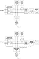
- a power supply system for a magnetic bearing is provided, as shown in Fig. 1 , which is a schematic structural view showing a power supply system for a magnetic bearing according to one embodiment of the present invention.
- the power supply system for a magnetic bearing may comprise a rectifying and filtering circuit 1, a power obtaining circuit 9, and a DC-DC power supply 2.
- the rectifying and filtering circuit 1 may be configured to rectify and filter an alternating current from an AC input power supply to obtain a first direct current with a first DC bus voltage.
- the first direct current is configured to supply power to the electric motor controller 5 of the electric motor 6 to which the magnetic bearing belongs. It should be understood that the magnetic bearing is configured to make the rotor of the electric motor 6 suspend.
- the rectifying and filtering circuit 1 may comprise a rectifying circuit and a filtering circuit.
- the rectifier circuit may be configured to rectify the alternating current from the AC input power supply to obtain a first direct current with a first DC bus voltage.
- the first direct current is configured to supply power to the electric motor controller 5 of the electric motor 6 to which the magnetic bearing belongs.
- the filter circuit may be configured to filter the first direct current and supply the filtered first direct current to at least one of the electric motor controller 5 or the power obtaining circuit 9.
- the alternating current from the AC input power becomes to be with a higher DC bus voltage (e.g., a DC bus voltage Ub) after being rectified and filtered by the rectifying and filtering circuit 1.
- the DC bus voltage Ub is supplied to the electric motor controller 5 for controlling the electric motor 6.
- the power obtaining circuit 9 may be configured to obtain a second direct current with a second DC bus voltage from the first direct current.
- the second DC bus voltage is within an input voltage range allowed by the DC-DC power supply 2.
- the first direct current first passes through a parallel circuit (i.e., the power obtaining circuit 9) comprising a voltage dividing resistor R and a switch K before being supplied to the DC-DC power supply 2.
- a parallel circuit i.e., the power obtaining circuit 9 comprising a voltage dividing resistor R and a switch K before being supplied to the DC-DC power supply 2.
- the DC-DC power supply 2 may be configured to convert the second direct current to a third direct current with a third DC bus voltage.
- the third direct current is configured to supply power to the bearing controller 4 of the magnetic bearing 3.
- the third DC bus voltage is within a power supply voltage range allowed by the bearing controller 4.
- the DC-DC power supply directly obtains power from the first direct current with the first DC bus voltage, and the bearing controller is entirely powered by the DC-DC power supply.
- the DC-DC power supply 2 converts the direct current supplied by the power obtaining circuit 9 into a direct current with a stable and lower voltage before supplying to the bearing controller 4 for controlling the magnetic bearing 3.
- the bearing controller 4 is entirely powered by the DC-DC power supply 2.
- the magnetic bearing controller is entirely powered by the DC-DC power supply, thereby improving the stability of running of the magnetic bearing.
- the problem that the DC bus voltage fluctuation affects the control stability of the magnetic bearing is solved and the power supply reliability is enhanced.
- the power obtaining circuit 9 may comprise a control switch (e.g., a switch K) and a voltage dividing resistor (e.g., a voltage dividing resistor R), which are shown as examples in Figs. 2 and 3 .
- a control switch e.g., a switch K
- a voltage dividing resistor e.g., a voltage dividing resistor R
- control switch and the voltage dividing resistor are arranged in parallel.
- the magnetic bearing controller is entirely powered by a DC-DC power supply which obtains power from the DC bus voltage through a parallel circuit comprising a voltage dividing resistor and a switch.
- the power obtaining circuit 9 may comprise a switch K, a voltage dividing resistor R, and the like.
- control switch and the voltage dividing resistor are cooperatively arranged, so that the magnetic bearing controller may be entirely powered by a DC-DC power supply, thereby reducing the selection difficulty and cost of the power device in the bearing controller.
- the problems of a high DC bus voltage as well as a difficult selection, a high cost and a difficult control of the power device in the bearing controller are solved.
- the resistance value of the voltage dividing resistor is a result by dividing a difference between the upper limit of a predetermined voltage range of the first DC bus and the upper limit of the input voltage range by a predetermined input current of the DC-DC power supply 2.
- the resistance value of the voltage dividing resistor is determined in a simple manner. The voltage is divided accurately according to the determined resistance value, which is favorable for enhancing the reliability and safety of power obtaining.
- control switch may comprise at least one of a solenoid valve, an electric valve, a mechanical switch, or a power switch.
- the voltage dividing resistor may comprise a sliding resistor.
- control switch in the structure in which the control switch and the voltage dividing resistor are arranged in parallel, the control switch may be configured to be in an on state, in a case where the AC input power supply is not off and the first DC bus voltage is within a predetermined voltage range, to exact the second direct current from the first direct current through a branch having the control switch.
- the magnetic bearing works normally
- the electric motor controller 5 is in a forward driving state
- the electric motor 6 runs normally and smoothly.
- the first DC bus voltage is stable with a voltage value Ub within an input range allowed by the DC-DC power supply 2.
- the voltage detection circuit 7 synchronously detects the value of the first DC bus voltage and feedbacks the value of the first DC bus voltage to the switch control circuit 8.
- the switch K is in an on state, and the first DC bus voltage is directly supplied to the DC-DC power supply 2.
- control switch in the structure in which the control switch and the voltage dividing resistor are arranged in parallel, the control switch may be also configured to be in an off state, in a case where the AC input power supply is not off and the first DC bus voltage is higher than an upper limit of the predetermined voltage range, to obtain the second direct current from the first direct current through a branch having the voltage dividing resistor.
- a fluctuation in the first DC bus voltage is caused.
- the value of the first DC bus voltage may exceed a maximum input value allowed by the DC-DC power supply 2.
- the DC-DC power supply 2 might be damaged and the entire magnetic suspension system might be further damaged.
- the switch control circuit 8 controls the switch K to be off.
- a voltage drop Ur is produced when the first direct current is supplied to the DC-DC power supply 2 through the voltage dividing resistor R.
- the DC-DC power supply 2 After the above processing, it is ensured that the DC-DC power supply 2 will not be damaged due to a rise in the first DC bus voltage, and the working voltage range of the DC-DC power supply 2 is widened. Meanwhile, since the DC-DC power supply 2 has the function of stabilizing a voltage, the output of the DC-DC power supply 2 is stable and will not affect the control of the magnetic bearing 3.
- control switch in the structure in which the control switch and the voltage dividing resistor are arranged in parallel, the control switch may be further configured to in an on state in a case where the AC input power is off, to obtain the second direct current from power generated by the electric motor 6 through the branch having the control switch.
- the electric motor 6 operates as a power generator, and the electric motor controller 5 is in a forward braking state to boost the voltage of the power generated by the electric motor 6 and feedback the boosted power to the DC bus to maintain the DC bus voltage to be within a reasonable range.
- the switch K is on, the DC-DC power supply 2 directly obtains power from the DC bus to maintain the magnetic bearing to continue to work until the rotation speed of the electric motor drops to zero.
- the bearing controller is entirely powered by the DC-DC power supply regardless of the state of the supply power system
- the voltage output by the DC-DC power supply is lower than the first DC bus voltage, a convenient selection and a low cost of the power device in the bearing controller is realized, and the control difficulty is also correspondingly reduced.
- the reliability of the supply power system for a magnetic bearing is improved.
- the bearing controller is entirely powered by the DC-DC power supply, the problem that the voltage of the power module of the bearing controller is not stable can be solved. Since the voltage output by the DC-DC power supply is lower than the first DC bus voltage, a convenient selection and a low cost of the power device in the bearing controller is realized, and the control difficulty is also correspondingly reduced. The reliability of the supply power system for a magnetic bearing is improved.
- the DC-DC power supply obtains power from the DC bus through a parallel circuit comprising a voltage dividing resistor and a switch. It is ensured that the DC-DC power supply may not be damaged due to a rise in the DC bus voltage, and the working voltage range of the DC-DC power supply is widened. The problem of damaging the DC-DC power supply and the entire magnetic bearing system due to the DC bus voltage exceeding a maximum input voltage allowed by the DC-DC power supply is solved, and the power supply system has a favorable stability and a high reliability.
- the power generated by the electric motor 6 may be configured to maintain the magnetic bearing 3 to continue to run until the electric motor 6 stops running.
- the electric motor controller 5 may also be configured to boost the voltage of the power generated by the electric motor 6 and feedback the boosted power to the DC bus.
- the electric motor serves as a generator, and the magnetic bearing is maintained to continue to work by the power generated by the electric motor, thereby improving the reliability of the magnetic bearing system.
- the problem that the entire system is damaged due to an abnormally power off of the AC input power supply is avoided, the stability and safety of run of the magnetic bearing is enhanced, and the problem that the rotor cannot be maintained to be suspended during an abnormal power off of the AC input power supply is solved.
- the power supply system may further comprise a switch control circuit 8.
- the switch control circuit 8 may be configured to control the control switch to be in an on or an off state.
- the switch control circuit controls the control switch to be in an on state or in an off state according to the first DC bus voltage.
- control switch is controlled through the switch control circuit, which is favorable for enhancing the flexibility and reliability of work of the power obtaining circuit.
- the power supply system may further comprise a voltage detection circuit 7.
- the voltage detection circuit 7 may be configured to detect whether the value of the first DC bus voltage is within the predetermined voltage range.
- the voltage detection circuit is configured to detect the value of the first DC bus voltage and feedback the value of the first DC bus voltage to the switch control circuit.
- a power supply system for a magnetic bearing is shown in Fig. 1 .
- the main members of the entire system i.e. the power supply system for a magnetic bearing
- the main members of the entire system may comprise: a rectifying and filtering circuit 1, a DC-DC power supply 2, a magnetic bearing 4 and a controller (i.e. a magnetic bearing controller 3), an electric motor 6 and a controller (i.e. an electric motor controller 5), a voltage detection circuit 7, a switch control circuit 8, and a power obtaining circuit 9 and the like.
- the voltage detection circuit 7 is configured to detect the value of the first DC bus voltage (e.g., a DC bus voltage Ub), and feedback the value of the first DC bus voltage to the switch control circuit 8 which controls the switch K to be in an on state or an off state according to the value of the first DC bus voltage.
- the first DC bus voltage e.g., a DC bus voltage Ub
- the DC bus voltage output by the rectifying and filtering circuit is detected by the voltage detection circuit, the stability and safety of the power supply of the magnetic bearing may be enhanced.
- the magnetic bearing controller is entirely powered by the DC-DC power supply, thereby solving the problem of damaging the DC-DC power supply and the entire magnetic bearing system due to the DC bus voltage exceeding a maximum allowed input value of the DC-DC power supply, and enhancing the reliability of the power supply.
- a control method of the power supply system for a magnetic bearing corresponding to the power supply system for a magnetic bearing is also provided.
- the control method of the power supply system for a magnetic bearing may comprise:
- An alternating current from the AC input power supply is rectified and filtered by the rectifying and filtering circuit 1 to obtain a first direct current with a first DC bus voltage.
- the first direct current is configured to supply power to the electric motor controller 5 of the electric motor 6 to which the magnetic bearing belongs.
- the rectifying and filtering circuit 1 may comprise a rectifying circuit and a filtering circuit.
- the rectifier circuit may be configured to rectify the alternating current from the AC input power supply to obtain a first direct current configured to supply power to the electric motor controller 5 of the electric motor 6 to which the magnetic bearing belongs.
- the filter circuit may be configured to filter the first direct current and supply the filtered first direct current to at least one of the electric motor controller 5 or the power obtaining circuit 9.
- the alternating current from the AC input power becomes to be a direct current with a higher voltage (e.g., a DC bus voltage Ub) after being rectified and filtered by the rectifying and filtering circuit 1.
- the DC bus voltage Ub is supplied to the electric motor controller 5 for controlling the electric motor 6.
- a second direct current with a second DC bus voltage is obtained from the first direct current by the power obtaining circuit 9.
- the second DC bus voltage is within an input voltage range allowed by the DC-DC power supply 2.
- the first direct current first passes through a parallel circuit (i.e., the power obtaining circuit 9) comprising a voltage dividing resistor R and a switch K before being supplied to the DC-DC power supply 2.
- a parallel circuit i.e., the power obtaining circuit 9 comprising a voltage dividing resistor R and a switch K before being supplied to the DC-DC power supply 2.
- the second direct current is converted to a third direct current with a third DC bus voltage by the DC-DC power supply 2.
- the third direct current is configured to supply power to the bearing controller 4 of the magnetic bearing 3.
- the third DC bus voltage is within a power supply voltage range allowed by the bearing controller 4.
- the DC-DC power supply directly obtains power from the first direct current supplied by the power obtaining circuit 9, and the bearing controller is entirely powered by the DC-DC power supply.
- the DC-DC power supply 2 converts the direct current supplied by the power obtaining circuit 9 into a direct current with a stable and lower voltage before supplying to the bearing controller 4 for controlling the magnetic bearing 3.
- the bearing controller 4 is entirely powered by the DC-DC power supply 2.
- the magnetic bearing controller is entirely powered by the DC-DC power supply, thereby improving the stability of running of the magnetic bearing.
- the problem that the DC bus voltage fluctuation affects the control stability of the magnetic bearing is solved and the power supply reliability is enhanced.
- the step that the second direct current is obtained from the first direct current by the power obtaining circuit 9 may comprise (21) to (23).
- the control switch is controlled to be in an on state, in a case where the AC input power supply is not off and the first DC bus voltage is within a predetermined voltage range, to obtain the second direct current from the first direct current through a branch having the control switch.
- the control switch is controlled to be in an off state, in a case where the AC input power supply is not off and the first DC bus voltage is higher than an upper limit of the predetermined voltage range, to obtain the second direct current from the first direct current through a branch having the voltage dividing resistor.
- the control switch is controlled to be in an on state in a case where the AC input power is off to obtain the second direct current from power generated by the electric motor (6) through the branch having the control switch.
- the DC-DC power supply obtains power from the DC bus through a parallel circuit comprising a voltage dividing resistor and a switch. It is ensured that the DC-DC power supply may not be damaged due to a rise in the DC bus voltage, and the working voltage range of the DC-DC power supply is widened. The problem of damaging the DC-DC power supply and the entire magnetic bearing system due to the DC bus voltage exceeding a maximum input voltage allowed by the DC-DC power supply is solved, and the power supply system has a favorable stability and a high reliability.
- the step that the second direct current is obtained from the power generated by the electric motor 6 through the branch having the control switch may comprise: running of the magnetic bearing 3 is maintained by the power generated by the electric motor 6 until the electric motor 6 stops running.
- the step that the second direct current is obtained from the power generated by the electric motor 6 through the branch having the control switch may further comprise: the power generated by the electric motor 6 is boosted to be with a higher voltage by the electric motor controller 5 and then feedbacked to the DC bus.
- the electric motor serves as a generator, and the magnetic bearing is maintained to continue to work by the power generated by the electric motor, thereby improving the reliability of the magnetic bearing system.
- the problem that the entire system is damaged due to an abnormally power off of the AC input power supply is avoided, the stability and safety of running of the magnetic bearing is enhanced, and the problem that the rotor cannot be maintained to be suspended during an abnormal power off of the AC input power supply is solved.
- control method may further comprise: the control switch is controlled to be in an on or an off state by the switch control circuit 8 in a case where the power supply system for a magnetic bearing further comprises a switch control circuit 8.
- control switch is controlled through the switch control circuit, which is favorable for enhancing the flexibility and reliability of work of the power obtaining circuit.
- control method may further comprise: the first DC bus voltage is detected whether being within the predetermined voltage range by the voltage detection circuit 7 in a case where the power supply system for a magnetic bearing further comprises the voltage detection circuit 7.
- the DC bus voltage output by the rectifying and filtering circuit is detected by the voltage detection circuit, the stability and safety of the power supply of the magnetic bearing may be enhanced.
- a power supply system for a magnetic bearing is shown in Fig. 1 .
- the main members of the entire system i.e. the power supply system for a magnetic bearing
- the main members of the entire system may comprise: a rectifying and filtering circuit 1, a DC-DC power supply 2, a magnetic bearing 4 and a controller (i.e. a magnetic bearing controller 3), an electric motor 6 and a controller (i.e. an electric motor controller 5), a voltage detection circuit 7, a switch control circuit 8, and a power obtaining circuit 9 and the like.
- the power obtaining circuit 9 may comprise a switch K, a voltage dividing resistor R, and the like.
- the operational principles of the power supply system for a magnetic bearing are as follows.
- the alternating current of the AC input power becomes to be direct current with a higher DC bus voltage (e.g., a DC bus voltage Ub) after being rectified and filtered by the rectifying and filtering circuit 1.
- a higher DC bus voltage e.g., a DC bus voltage Ub
- the direct current with the DC bus voltage Ub is supplied to the electric motor controller 5 for controlling the electric motor 6.
- the direct current first passes through a parallel circuit (i.e., the power obtaining circuit 9) comprising a voltage dividing resistor R and a switch K before being supplied to the DC-DC power supply 2.
- a parallel circuit i.e., the power obtaining circuit 9 comprising a voltage dividing resistor R and a switch K before being supplied to the DC-DC power supply 2.
- the DC-DC power supply 2 converts the direct current supplied by the power obtaining circuit 9 into a direct current with a stable and lower voltage before supplying to the bearing controller 4 for controlling the magnetic bearing 3.
- the bearing controller 4 is entirely powered by the DC-DC power supply 2.
- the voltage detection circuit 7 is configured to detect the value of the DC bus voltage (e.g., a DC bus voltage Ub), and feedback the value of the DC bus voltage to the switch control circuit 8 which controls the switch K to be in an on state or an off state according to the value of the DC bus voltage.
- the DC bus voltage e.g., a DC bus voltage Ub
- the switch control circuit 8 controls the switch K to be off.
- a voltage drop Ur is produced when the DC bus voltage is supplied to the DC-DC power supply 2 through the voltage dividing resistor R.
- the DC-DC power supply 2 After the above processing, it is ensured that the DC-DC power supply 2 will not be damaged due to a rise in the DC bus voltage, and the working voltage range of the DC-DC power supply 2 is widened. Meanwhile, since the DC-DC power supply 2 has the function of stabilizing a voltage, the output of the DC-DC power supply 2 is stable and will not affect the control of the magnetic bearing 3.
- the electric motor 6 operates as a power generator, and the electric motor controller 5 is in a forward braking state to boost the voltage of the power generated by the electric motor 6 and feedback the boosted power to the DC bus to maintain the DC bus voltage to be within a reasonable range.
- the switch K is on, the DC-DC power supply 2 directly obtains power from the DC bus to maintain the magnetic bearing to continue to work until the rotation speed of the electric motor drops to zero.
- the bearing controller is entirely powered by the DC-DC power supply regardless of the state of the supply power system
- the voltage output by the DC-DC power supply is lower than the DC bus voltage, a convenient selection and a low cost of the power device in bearing controller is realized, and the control difficulty is also correspondingly reduced.
- the reliability of the supply power system for a magnetic bearing is improved.
- the bearing controller is entirely powered by the DC-DC power supply, the problem that the voltage of the power module of the bearing controller is not stable can be solved. Since the voltage output by the DC-DC power supply is lower than the DC bus voltage, a convenient selection and a low cost of the power device in the bearing controller is realized, and the control difficulty is also correspondingly reduced. The reliability of the supply power system for a magnetic bearing is improved.
- the magnetic bearing controller is entirely powered by the DC-DC power supply in a simple structure, thereby reducing the selection difficulty and cost of the power device in the bearing controller.
- the problems of a high DC bus voltage as well as a difficult selection, a high cost and a difficult control of the power device in the bearing controller are solved.
Landscapes
- Engineering & Computer Science (AREA)
- General Engineering & Computer Science (AREA)
- Power Engineering (AREA)
- Physics & Mathematics (AREA)
- Electromagnetism (AREA)
- Mechanical Engineering (AREA)
- Chemical & Material Sciences (AREA)
- Combustion & Propulsion (AREA)
- Magnetic Bearings And Hydrostatic Bearings (AREA)
- Rectifiers (AREA)
- Control Of Electric Motors In General (AREA)
- Connection Of Motors, Electrical Generators, Mechanical Devices, And The Like (AREA)
Claims (9)
- Stromversorgungssystem für ein Magnetlager (3), umfassend: eine Gleichrichtungs- und Filterschaltung (1), eine Strombeschaffungsschaltung (9) und eine Gleichstrom-Gleichstrom-Stromversorgung (2), wobei:die Gleichrichtungs- und Filterschaltung (1) zum Gleichrichten und Filtern eines Wechselstroms aus einer Wechselstrom-Eingangsstromversorgung zum Beschaffen eines ersten Gleichstroms mit einer ersten Gleichstrom-Zwischenkreisspannung konfiguriert ist, wobei der erste Gleichstrom zum Versorgen einer Elektromotor-Steuerung (5) eines Elektromotors (6), zu dem das Magnetlager (3) gehört, mit Strom konfiguriert ist;die Strombeschaffungsschaltung (9) zum Beschaffen eines zweiten Gleichstroms mit einer zweiten Gleichstrom-Zwischenkreisspannung aus dem ersten Gleichstrom konfiguriert ist, wobei die zweite Gleichstrom-Zwischenkreisspannung innerhalb eines von der Gleichstrom-Gleichstrom-Stromversorgung (2) erlaubten Eingangsspannungsbereichs liegt; unddie Gleichstrom-Gleichstrom-Stromversorgung (2) zum Umwandeln des zweiten Gleichstroms in einen dritten Gleichstrom mit einer dritten Gleichstrom-Zwischenkreisspannung konfiguriert ist, wobei der dritte Gleichstrom zum Versorgen einer Lagersteuerung (4) des Magnetlagers (3) konfiguriert ist, wobei das Stromversorgungssystem dadurch gekennzeichnet ist, dassdie Strombeschaffungsschaltung (9) einen Steuerschalter (K) und einen Spannungsteilerwiderstand (R) umfasst, die parallel angeordnet sind, wobei der Steuerschalter (K) konfiguriert ist, um wie folgt zu sein:in einem Ein-Zustand, falls die Wechselstrom-Eingangsstromversorgung nicht ausgeschaltet ist und die erste Gleichstrom-Zwischenkreisspannung innerhalb eines vorbestimmten Spannungsbereichs liegt, um den zweiten Gleichstrom durch einen Stromkreis, der den Steuerschalter (K) aufweist, aus dem ersten Gleichstrom zu beschaffen; oderin einem Aus-Zustand, falls die Wechselstrom-Eingangsstromversorgung nicht ausgeschaltet ist und die erste Gleichstrom-Zwischenkreisspannung höher ist als eine Obergrenze des vorbestimmten Spannungsbereichs, um den zweiten Gleichstrom durch einen Stromkreis, der den Spannungsteilungswiderstand (R) aufweist, aus dem ersten Gleichstrom zu beschaffen; oderin einem Ein-Zustand, falls die Wechselstrom-Eingangsstromversorgung ausgeschaltet ist, um den zweiten Gleichstrom aus von dem Elektromotor (6) erzeugtem Strom durch den Stromkreis, der den Steuerschalter (K) aufweist, zu beschaffen.
- Stromversorgungssystem nach Anspruch 1, dadurch gekennzeichnet, dass ein Widerstandswert des Spannungsteilerwiderstands (R) ein Ergebnis des Dividierens einer Differenz zwischen der Obergrenze des vorbestimmten Spannungsbereichs und einer Obergrenze des Eingangsspannungsbereichs durch einen vorbestimmten Eingangsstrom der Gleichstrom-Gleichstrom-Stromversorgung (2) ist.
- Stromversorgungssystem nach Anspruchs 1 oder 2, dadurch gekennzeichnet, dass:der Steuerschalter (K) wenigstens eines von einem Magnetventil, einem elektrischen Ventil, einem mechanischen Schalter oder einem Netzschalter umfasst;und/oderder Spannungsteilungswiderstand (R) einen Schiebewiderstand umfasst.
- Stromversorgungssystem nach einem der Ansprüche 1 bis 3, dadurch gekennzeichnet, dass:der von dem Elektromotor (6) erzeugte Strom zum Aufrechterhalten des Betriebs des Magnetlagers (3), bis der Elektromotor (6) zum Stillstand kommt, konfiguriert ist;und/oderdie Elektromotor-Steuerung (5) ferner zum Erhöhen einer Spannung des von dem Elektromotor (6) erzeugten Stroms konfiguriert ist, um den zweiten Gleichstrom durch den Stromkreis zu beschaffen, der den Steuerschalter (K) aufweist.
- Stromversorgungssystem nach einem der Ansprüche 1 bis 4, dadurch gekennzeichnet, dass es ferner eine Schaltersteuerschaltung (8) umfasst, die zum Steuern des Steuerschalters (K), so dass er in einem Ein-Zustand oder einem Aus-Zustand ist, konfiguriert ist.
- Stromversorgungssystem nach einem der Ansprüche 1 bis 5, dadurch gekennzeichnet, dass es ferner eine Spannungserkennungsschaltung (7) umfasst, die zum Erkennen, ob die erste Gleichstrom-Zwischenkreisspannung innerhalb des vorbestimmten Spannungsbereichs ist, konfiguriert ist.
- Steuerverfahren eines Stromversorgungssystems für ein Magnetlager (3), umfassend:Gleichrichten und Filtern, durch eine Gleichrichtungs- und Filterschaltung (1), eines Wechselstroms aus einer Wechselstrom-Eingangsstromversorgung zum Beschaffen eines ersten Gleichstroms mit einer ersten Gleichstrom-Zwischenkreisspannung, wobei der erste Gleichstrom zum Versorgen einer Elektromotor-Steuerung (5) eines Elektromotors (6), zu dem das Magnetlager (3) gehört, mit Strom konfiguriert ist;Beschaffen, durch eine Strombeschaffungsschaltung (9) zum Beschaffen eines zweiten Gleichstroms mit einer zweiten Gleichstrom-Zwischenkreisspannung aus dem ersten Gleichstrom, wobei die zweite Gleichstrom-Zwischenkreisspannung innerhalb eines von der Gleichstrom-Gleichstrom-Stromversorgung (2) erlaubten Eingangsspannungsbereichs liegt; undUmwandeln, durch die Gleichstrom-Gleichstrom-Stromversorgung (2), des zweiten Gleichstroms in einen dritten Gleichstrom mit einer dritten Gleichstrom-Zwischenkreisspannung, wobei der dritte Gleichstrom zum Versorgen einer Lagersteuerung (4) des Magnetlagers (3) konfiguriert ist, undwobei der Schritt des Beschaffens, durch die Strombeschaffungsschaltung (9), des zweiten Gleichstroms aus dem ersten Gleichstrom umfasst:Steuern eines Steuerschalters (K) in der Strombeschaffungsschaltung (9), so dass er in einem Ein-Zustand ist, falls die Wechselstrom-Eingangsstromversorgung nicht ausgeschaltet ist und die erste Gleichstrom-Zwischenkreisspannung innerhalb eines vorbestimmten Spannungsbereichs liegt, um den zweiten Gleichstrom durch einen Stromkreis, der den Steuerschalter (K) aufweist, aus dem ersten Gleichstrom zu beschaffen; oderSteuern des Steuerschalters (K), so dass er in einem Aus-Zustand ist, falls die Wechselstrom-Eingangsstromversorgung nicht ausgeschaltet ist und die erste Gleichstrom-Zwischenkreisspannung höher ist als eine Obergrenze des vorbestimmten Spannungsbereichs, um den zweiten Gleichstrom durch einen Stromkreis, der den Spannungsteilungswiderstand (R) in der Strombeschaffungsschaltung (9) aufweist, aus dem ersten Gleichstrom zu beschaffen; oderSteuern des Steuerschalters (K), so dass er in einem Ein-Zustand ist, falls der Wechselstrom-Eingangsstrom ausgeschaltet ist, um den zweiten Gleichstrom aus von dem Elektromotor (6) erzeugtem Strom durch den Stromkreis, der den Steuerschalter (K) aufweist, zu beschaffen.
- Steuerverfahren nach Anspruch 7, dadurch gekennzeichnet, dass der Schritt des Beschaffens des zweiten Gleichstroms aus dem von dem Elektromotor (6) erzeugten Strom durch den Stromkreis, der den Steuerschalter (K) aufweist, umfasst:Aufrechterhalten, durch den von dem Elektromotor (6) erzeugten Strom, des Betriebs des Magnetlagers (3), bis der Elektromotor (6) zum Stillstand kommt;und/oderErhöhen, durch die Elektromotor-Steuerung (5), einer Spannung des von dem Elektromotor (6) erzeugten Stroms konfiguriert ist, um den zweiten Gleichstrom durch den Stromkreis zu beschaffen, der den Steuerschalter (K) aufweist.
- Steuerverfahren nach einem der Ansprüche 7 bis 8, dadurch gekennzeichnet, dass es ferner umfasst:falls das Stromversorgungssystem für ein Magnetlager (3) ferner eine Schaltersteuerschaltung (8) umfasst, Steuern des Steuerschalters (K), so dass er in einem Ein- oder einem Aus-Zustand ist, durch dieSchaltersteuerschaltung (8);und/oderfalls das Stromversorgungssystem für ein Magnetlager (3) ferner eine Spannungserkennungsschaltung (7) umfasst, Erkennen, ob die erste Gleichstrom-Zwischenkreisspannung innerhalb des vorbestimmten Spannungsbereichs ist, durch die Spannungserkennungsschaltung (7).
Applications Claiming Priority (2)
| Application Number | Priority Date | Filing Date | Title |
|---|---|---|---|
| CN201711085437.XA CN108167330B (zh) | 2017-11-07 | 2017-11-07 | 一种磁悬浮轴承供电系统及其控制方法 |
| PCT/CN2018/112306 WO2019091297A1 (zh) | 2017-11-07 | 2018-10-29 | 一种磁悬浮轴承供电系统及其控制方法 |
Publications (3)
| Publication Number | Publication Date |
|---|---|
| EP3640488A1 EP3640488A1 (de) | 2020-04-22 |
| EP3640488A4 EP3640488A4 (de) | 2020-09-02 |
| EP3640488B1 true EP3640488B1 (de) | 2022-02-23 |
Family
ID=62526976
Family Applications (1)
| Application Number | Title | Priority Date | Filing Date |
|---|---|---|---|
| EP18875241.4A Active EP3640488B1 (de) | 2017-11-07 | 2018-10-29 | Stromversorgungssystem für magnetlager und steuerverfahren dafür |
Country Status (6)
| Country | Link |
|---|---|
| US (1) | US11454278B2 (de) |
| EP (1) | EP3640488B1 (de) |
| JP (1) | JP7130731B2 (de) |
| KR (1) | KR102557982B1 (de) |
| CN (1) | CN108167330B (de) |
| WO (1) | WO2019091297A1 (de) |
Families Citing this family (5)
| Publication number | Priority date | Publication date | Assignee | Title |
|---|---|---|---|---|
| CN108167330B (zh) | 2017-11-07 | 2019-09-03 | 珠海格力电器股份有限公司 | 一种磁悬浮轴承供电系统及其控制方法 |
| CN110988441B (zh) * | 2019-12-25 | 2023-11-28 | 联合汽车电子有限公司 | 直流母线电压监控系统及方法 |
| CN112039190A (zh) * | 2020-07-27 | 2020-12-04 | 珠海格力电器股份有限公司 | 一种磁悬浮系统的供电控制装置、方法和磁悬浮系统 |
| CN112713644B (zh) * | 2020-12-11 | 2024-03-08 | 珠海格力电器股份有限公司 | 一种轴承控制器的供电控制装置、方法和磁悬浮系统 |
| CN114844193B (zh) * | 2022-03-16 | 2024-11-05 | 宁波招宝磁业有限公司 | 一种磁悬浮电机组 |
Family Cites Families (18)
| Publication number | Priority date | Publication date | Assignee | Title |
|---|---|---|---|---|
| JPH0680328B2 (ja) * | 1986-06-16 | 1994-10-12 | 三菱重工業株式会社 | 磁気軸受制御装置 |
| FR2654875B1 (fr) | 1989-11-23 | 1992-03-13 | Cit Alcatel | Ensemble d'alimentation electrique d'une pompe a vide a paliers magnetiques, avec alimentation auxiliaire des paliers en cas de coupure du courant du secteur. |
| JP2549159Y2 (ja) | 1991-05-13 | 1997-09-30 | 株式会社荏原製作所 | 磁気軸受を用いた誘導電動機の電源装置 |
| JP3519771B2 (ja) | 1994-02-28 | 2004-04-19 | Ntn株式会社 | 磁気軸受装置 |
| JP3698773B2 (ja) * | 1995-10-20 | 2005-09-21 | 光洋精工株式会社 | ターボ分子ポンプ |
| DE59706479D1 (de) * | 1996-07-25 | 2002-04-04 | Lust Antriebstechnik Gmbh | Anordnung und Verfahren zum Betreiben einer magnetgelagerten, elektromotorischen Antriebsvorrichtung bei einer Netzstörung |
| AUPR002400A0 (en) | 2000-09-11 | 2000-10-05 | Turbocor Inc | Power supply for high speed motor |
| CN1599239A (zh) * | 2004-09-23 | 2005-03-23 | 山东科技大学 | 基于fpga的磁悬浮轴承功率放大器 |
| CN100444060C (zh) * | 2005-01-27 | 2008-12-17 | 山东大学 | 磁悬浮轴承监测、控制一体化装置 |
| CN101510098A (zh) | 2009-03-17 | 2009-08-19 | 中国船舶重工集团公司第七一〇研究所 | 混合磁路磁悬浮轴承集成控制器 |
| CN202679265U (zh) | 2011-11-03 | 2013-01-16 | 上海大学 | 主动磁悬浮轴承系统智能开关电源 |
| US9302912B2 (en) * | 2012-03-28 | 2016-04-05 | Mks Instruments, Inc. | Compact, configurable power supply for energizing ozone-producing cells |
| CN202721450U (zh) | 2012-05-29 | 2013-02-06 | 深圳市海浦蒙特科技有限公司 | 全可控能量回馈装置 |
| CN103701336B (zh) | 2014-01-08 | 2016-08-17 | 北京航空航天大学 | 一种用于磁悬浮永磁电机控制系统的开关电源装置 |
| CN203691301U (zh) | 2014-01-24 | 2014-07-02 | 南京埃斯顿自动控制技术有限公司 | 一种适用于工业机器人驱动器的上电和制动电路 |
| CN105151927B (zh) * | 2015-05-16 | 2018-03-20 | 焦作市华鹰机电技术有限公司 | 磁悬浮导向直驱运输系统及其控制方法 |
| CN106849789A (zh) | 2017-02-22 | 2017-06-13 | 南京磁谷科技有限公司 | 一种磁悬浮高速电机发电模式的控制方法 |
| CN108167330B (zh) | 2017-11-07 | 2019-09-03 | 珠海格力电器股份有限公司 | 一种磁悬浮轴承供电系统及其控制方法 |
-
2017
- 2017-11-07 CN CN201711085437.XA patent/CN108167330B/zh active Active
-
2018
- 2018-10-29 JP JP2020504679A patent/JP7130731B2/ja active Active
- 2018-10-29 EP EP18875241.4A patent/EP3640488B1/de active Active
- 2018-10-29 US US16/633,958 patent/US11454278B2/en active Active
- 2018-10-29 WO PCT/CN2018/112306 patent/WO2019091297A1/zh not_active Ceased
- 2018-10-29 KR KR1020207002886A patent/KR102557982B1/ko active Active
Also Published As
| Publication number | Publication date |
|---|---|
| JP2021508431A (ja) | 2021-03-04 |
| WO2019091297A1 (zh) | 2019-05-16 |
| EP3640488A4 (de) | 2020-09-02 |
| CN108167330B (zh) | 2019-09-03 |
| KR20200076663A (ko) | 2020-06-29 |
| KR102557982B1 (ko) | 2023-07-20 |
| CN108167330A (zh) | 2018-06-15 |
| US11454278B2 (en) | 2022-09-27 |
| EP3640488A1 (de) | 2020-04-22 |
| US20200208679A1 (en) | 2020-07-02 |
| JP7130731B2 (ja) | 2022-09-05 |
Similar Documents
| Publication | Publication Date | Title |
|---|---|---|
| EP3640488A1 (de) | Stromversorgungssystem für magnetlager und steuerverfahren dafür | |
| KR100260665B1 (ko) | 자기 베어링 장치용 전원 회로 | |
| CN103701336B (zh) | 一种用于磁悬浮永磁电机控制系统的开关电源装置 | |
| US9093892B2 (en) | Apparatus and method for controlling medium voltage inverter | |
| CN103208960A (zh) | 一种励磁控制电路及其电励磁风电系统 | |
| CN107086843A (zh) | 电机驱动系统和变频空调器 | |
| EP3872976B1 (de) | Stromverbrauchsteuerungsvorrichtung, magnetschwebesystem und stromverbrauchsteuerungsverfahren | |
| CN105711604A (zh) | 动车组救援回送装置 | |
| WO2017125072A1 (zh) | 一种用于磁悬浮离心机的停机方法及装置 | |
| CN112039190A (zh) | 一种磁悬浮系统的供电控制装置、方法和磁悬浮系统 | |
| CN110932566B (zh) | 一种船用恒频稳压电源的主电路及其工作方法 | |
| JP2009261161A (ja) | 瞬時電圧低下保護装置 | |
| EP2212987B1 (de) | Belastungsbegrenzung für eine stromquelle | |
| CN117117977B (zh) | 一种光伏热泵的电源系统、热泵系统及控制方法 | |
| CN106470001A (zh) | 一种变频器和电机控制系统 | |
| JP2010154650A (ja) | 交流電動機駆動装置 | |
| CN201947218U (zh) | 一种单相感应电机调速控制系统 | |
| CN104484004A (zh) | 一种在线式ups的控制装置及在线式ups | |
| KR20150005822A (ko) | H-브리지 멀티 레벨 인버터의 순간정전 제어 장치 및 방법 | |
| JP2000192888A (ja) | コンプレッサ制御装置 | |
| CN108880276A (zh) | 储纱器控制器 | |
| CN107579542B (zh) | 一种抑制逆变器输出端过电压的方法、装置及系统 | |
| CN220440588U (zh) | 一种风电变桨系统的交流干扰抑制装置 | |
| CN206471811U (zh) | 一种用于sfc系统的接地保护装置 | |
| KR102530374B1 (ko) | 전력 변환 장치 및 이를 포함하는 공기 조화기 |
Legal Events
| Date | Code | Title | Description |
|---|---|---|---|
| STAA | Information on the status of an ep patent application or granted ep patent |
Free format text: STATUS: THE INTERNATIONAL PUBLICATION HAS BEEN MADE |
|
| PUAI | Public reference made under article 153(3) epc to a published international application that has entered the european phase |
Free format text: ORIGINAL CODE: 0009012 |
|
| STAA | Information on the status of an ep patent application or granted ep patent |
Free format text: STATUS: REQUEST FOR EXAMINATION WAS MADE |
|
| 17P | Request for examination filed |
Effective date: 20200117 |
|
| AK | Designated contracting states |
Kind code of ref document: A1 Designated state(s): AL AT BE BG CH CY CZ DE DK EE ES FI FR GB GR HR HU IE IS IT LI LT LU LV MC MK MT NL NO PL PT RO RS SE SI SK SM TR |
|
| AX | Request for extension of the european patent |
Extension state: BA ME |
|
| A4 | Supplementary search report drawn up and despatched |
Effective date: 20200804 |
|
| RIC1 | Information provided on ipc code assigned before grant |
Ipc: H02K 7/09 20060101ALI20200729BHEP Ipc: H02K 7/16 20060101ALI20200729BHEP Ipc: F16C 32/04 20060101AFI20200729BHEP Ipc: H02N 15/00 20060101ALI20200729BHEP Ipc: H02M 1/00 20060101ALI20200729BHEP Ipc: H02M 1/36 20070101ALI20200729BHEP Ipc: H02M 3/04 20060101ALI20200729BHEP |
|
| DAV | Request for validation of the european patent (deleted) | ||
| DAX | Request for extension of the european patent (deleted) | ||
| REG | Reference to a national code |
Ref country code: DE Ref legal event code: R079 Ref document number: 602018031416 Country of ref document: DE Free format text: PREVIOUS MAIN CLASS: F16C0032040000 Ipc: H02M0005458000 |
|
| GRAP | Despatch of communication of intention to grant a patent |
Free format text: ORIGINAL CODE: EPIDOSNIGR1 |
|
| STAA | Information on the status of an ep patent application or granted ep patent |
Free format text: STATUS: GRANT OF PATENT IS INTENDED |
|
| RIC1 | Information provided on ipc code assigned before grant |
Ipc: H02N 15/00 20060101ALI20211005BHEP Ipc: F16C 32/04 20060101ALI20211005BHEP Ipc: H02M 5/458 20060101AFI20211005BHEP |
|
| INTG | Intention to grant announced |
Effective date: 20211019 |
|
| GRAS | Grant fee paid |
Free format text: ORIGINAL CODE: EPIDOSNIGR3 |
|
| GRAA | (expected) grant |
Free format text: ORIGINAL CODE: 0009210 |
|
| STAA | Information on the status of an ep patent application or granted ep patent |
Free format text: STATUS: THE PATENT HAS BEEN GRANTED |
|
| AK | Designated contracting states |
Kind code of ref document: B1 Designated state(s): AL AT BE BG CH CY CZ DE DK EE ES FI FR GB GR HR HU IE IS IT LI LT LU LV MC MK MT NL NO PL PT RO RS SE SI SK SM TR |
|
| REG | Reference to a national code |
Ref country code: GB Ref legal event code: FG4D |
|
| REG | Reference to a national code |
Ref country code: CH Ref legal event code: EP |
|
| REG | Reference to a national code |
Ref country code: AT Ref legal event code: REF Ref document number: 1471220 Country of ref document: AT Kind code of ref document: T Effective date: 20220315 |
|
| REG | Reference to a national code |
Ref country code: IE Ref legal event code: FG4D |
|
| REG | Reference to a national code |
Ref country code: DE Ref legal event code: R096 Ref document number: 602018031416 Country of ref document: DE |
|
| REG | Reference to a national code |
Ref country code: LT Ref legal event code: MG9D |
|
| REG | Reference to a national code |
Ref country code: NL Ref legal event code: MP Effective date: 20220223 |
|
| REG | Reference to a national code |
Ref country code: AT Ref legal event code: MK05 Ref document number: 1471220 Country of ref document: AT Kind code of ref document: T Effective date: 20220223 |
|
| PG25 | Lapsed in a contracting state [announced via postgrant information from national office to epo] |
Ref country code: SE Free format text: LAPSE BECAUSE OF FAILURE TO SUBMIT A TRANSLATION OF THE DESCRIPTION OR TO PAY THE FEE WITHIN THE PRESCRIBED TIME-LIMIT Effective date: 20220223 Ref country code: RS Free format text: LAPSE BECAUSE OF FAILURE TO SUBMIT A TRANSLATION OF THE DESCRIPTION OR TO PAY THE FEE WITHIN THE PRESCRIBED TIME-LIMIT Effective date: 20220223 Ref country code: PT Free format text: LAPSE BECAUSE OF FAILURE TO SUBMIT A TRANSLATION OF THE DESCRIPTION OR TO PAY THE FEE WITHIN THE PRESCRIBED TIME-LIMIT Effective date: 20220623 Ref country code: NO Free format text: LAPSE BECAUSE OF FAILURE TO SUBMIT A TRANSLATION OF THE DESCRIPTION OR TO PAY THE FEE WITHIN THE PRESCRIBED TIME-LIMIT Effective date: 20220523 Ref country code: NL Free format text: LAPSE BECAUSE OF FAILURE TO SUBMIT A TRANSLATION OF THE DESCRIPTION OR TO PAY THE FEE WITHIN THE PRESCRIBED TIME-LIMIT Effective date: 20220223 Ref country code: LT Free format text: LAPSE BECAUSE OF FAILURE TO SUBMIT A TRANSLATION OF THE DESCRIPTION OR TO PAY THE FEE WITHIN THE PRESCRIBED TIME-LIMIT Effective date: 20220223 Ref country code: HR Free format text: LAPSE BECAUSE OF FAILURE TO SUBMIT A TRANSLATION OF THE DESCRIPTION OR TO PAY THE FEE WITHIN THE PRESCRIBED TIME-LIMIT Effective date: 20220223 Ref country code: ES Free format text: LAPSE BECAUSE OF FAILURE TO SUBMIT A TRANSLATION OF THE DESCRIPTION OR TO PAY THE FEE WITHIN THE PRESCRIBED TIME-LIMIT Effective date: 20220223 Ref country code: BG Free format text: LAPSE BECAUSE OF FAILURE TO SUBMIT A TRANSLATION OF THE DESCRIPTION OR TO PAY THE FEE WITHIN THE PRESCRIBED TIME-LIMIT Effective date: 20220523 |
|
| PG25 | Lapsed in a contracting state [announced via postgrant information from national office to epo] |
Ref country code: PL Free format text: LAPSE BECAUSE OF FAILURE TO SUBMIT A TRANSLATION OF THE DESCRIPTION OR TO PAY THE FEE WITHIN THE PRESCRIBED TIME-LIMIT Effective date: 20220223 Ref country code: LV Free format text: LAPSE BECAUSE OF FAILURE TO SUBMIT A TRANSLATION OF THE DESCRIPTION OR TO PAY THE FEE WITHIN THE PRESCRIBED TIME-LIMIT Effective date: 20220223 Ref country code: GR Free format text: LAPSE BECAUSE OF FAILURE TO SUBMIT A TRANSLATION OF THE DESCRIPTION OR TO PAY THE FEE WITHIN THE PRESCRIBED TIME-LIMIT Effective date: 20220524 Ref country code: FI Free format text: LAPSE BECAUSE OF FAILURE TO SUBMIT A TRANSLATION OF THE DESCRIPTION OR TO PAY THE FEE WITHIN THE PRESCRIBED TIME-LIMIT Effective date: 20220223 Ref country code: AT Free format text: LAPSE BECAUSE OF FAILURE TO SUBMIT A TRANSLATION OF THE DESCRIPTION OR TO PAY THE FEE WITHIN THE PRESCRIBED TIME-LIMIT Effective date: 20220223 |
|
| PG25 | Lapsed in a contracting state [announced via postgrant information from national office to epo] |
Ref country code: IS Free format text: LAPSE BECAUSE OF FAILURE TO SUBMIT A TRANSLATION OF THE DESCRIPTION OR TO PAY THE FEE WITHIN THE PRESCRIBED TIME-LIMIT Effective date: 20220623 |
|
| PG25 | Lapsed in a contracting state [announced via postgrant information from national office to epo] |
Ref country code: SM Free format text: LAPSE BECAUSE OF FAILURE TO SUBMIT A TRANSLATION OF THE DESCRIPTION OR TO PAY THE FEE WITHIN THE PRESCRIBED TIME-LIMIT Effective date: 20220223 Ref country code: SK Free format text: LAPSE BECAUSE OF FAILURE TO SUBMIT A TRANSLATION OF THE DESCRIPTION OR TO PAY THE FEE WITHIN THE PRESCRIBED TIME-LIMIT Effective date: 20220223 Ref country code: RO Free format text: LAPSE BECAUSE OF FAILURE TO SUBMIT A TRANSLATION OF THE DESCRIPTION OR TO PAY THE FEE WITHIN THE PRESCRIBED TIME-LIMIT Effective date: 20220223 Ref country code: EE Free format text: LAPSE BECAUSE OF FAILURE TO SUBMIT A TRANSLATION OF THE DESCRIPTION OR TO PAY THE FEE WITHIN THE PRESCRIBED TIME-LIMIT Effective date: 20220223 Ref country code: DK Free format text: LAPSE BECAUSE OF FAILURE TO SUBMIT A TRANSLATION OF THE DESCRIPTION OR TO PAY THE FEE WITHIN THE PRESCRIBED TIME-LIMIT Effective date: 20220223 Ref country code: CZ Free format text: LAPSE BECAUSE OF FAILURE TO SUBMIT A TRANSLATION OF THE DESCRIPTION OR TO PAY THE FEE WITHIN THE PRESCRIBED TIME-LIMIT Effective date: 20220223 |
|
| REG | Reference to a national code |
Ref country code: DE Ref legal event code: R097 Ref document number: 602018031416 Country of ref document: DE |
|
| PG25 | Lapsed in a contracting state [announced via postgrant information from national office to epo] |
Ref country code: AL Free format text: LAPSE BECAUSE OF FAILURE TO SUBMIT A TRANSLATION OF THE DESCRIPTION OR TO PAY THE FEE WITHIN THE PRESCRIBED TIME-LIMIT Effective date: 20220223 |
|
| PLBE | No opposition filed within time limit |
Free format text: ORIGINAL CODE: 0009261 |
|
| STAA | Information on the status of an ep patent application or granted ep patent |
Free format text: STATUS: NO OPPOSITION FILED WITHIN TIME LIMIT |
|
| 26N | No opposition filed |
Effective date: 20221124 |
|
| PG25 | Lapsed in a contracting state [announced via postgrant information from national office to epo] |
Ref country code: SI Free format text: LAPSE BECAUSE OF FAILURE TO SUBMIT A TRANSLATION OF THE DESCRIPTION OR TO PAY THE FEE WITHIN THE PRESCRIBED TIME-LIMIT Effective date: 20220223 |
|
| PG25 | Lapsed in a contracting state [announced via postgrant information from national office to epo] |
Ref country code: MC Free format text: LAPSE BECAUSE OF FAILURE TO SUBMIT A TRANSLATION OF THE DESCRIPTION OR TO PAY THE FEE WITHIN THE PRESCRIBED TIME-LIMIT Effective date: 20220223 |
|
| REG | Reference to a national code |
Ref country code: BE Ref legal event code: MM Effective date: 20221031 |
|
| GBPC | Gb: european patent ceased through non-payment of renewal fee |
Effective date: 20221029 |
|
| PG25 | Lapsed in a contracting state [announced via postgrant information from national office to epo] |
Ref country code: LU Free format text: LAPSE BECAUSE OF NON-PAYMENT OF DUE FEES Effective date: 20221029 |
|
| P01 | Opt-out of the competence of the unified patent court (upc) registered |
Effective date: 20230530 |
|
| PG25 | Lapsed in a contracting state [announced via postgrant information from national office to epo] |
Ref country code: IT Free format text: LAPSE BECAUSE OF FAILURE TO SUBMIT A TRANSLATION OF THE DESCRIPTION OR TO PAY THE FEE WITHIN THE PRESCRIBED TIME-LIMIT Effective date: 20220223 |
|
| PG25 | Lapsed in a contracting state [announced via postgrant information from national office to epo] |
Ref country code: BE Free format text: LAPSE BECAUSE OF NON-PAYMENT OF DUE FEES Effective date: 20221031 |
|
| PG25 | Lapsed in a contracting state [announced via postgrant information from national office to epo] |
Ref country code: IE Free format text: LAPSE BECAUSE OF NON-PAYMENT OF DUE FEES Effective date: 20221029 Ref country code: GB Free format text: LAPSE BECAUSE OF NON-PAYMENT OF DUE FEES Effective date: 20221029 |
|
| PG25 | Lapsed in a contracting state [announced via postgrant information from national office to epo] |
Ref country code: HU Free format text: LAPSE BECAUSE OF FAILURE TO SUBMIT A TRANSLATION OF THE DESCRIPTION OR TO PAY THE FEE WITHIN THE PRESCRIBED TIME-LIMIT; INVALID AB INITIO Effective date: 20181029 |
|
| PG25 | Lapsed in a contracting state [announced via postgrant information from national office to epo] |
Ref country code: CY Free format text: LAPSE BECAUSE OF FAILURE TO SUBMIT A TRANSLATION OF THE DESCRIPTION OR TO PAY THE FEE WITHIN THE PRESCRIBED TIME-LIMIT Effective date: 20220223 |
|
| PG25 | Lapsed in a contracting state [announced via postgrant information from national office to epo] |
Ref country code: MK Free format text: LAPSE BECAUSE OF FAILURE TO SUBMIT A TRANSLATION OF THE DESCRIPTION OR TO PAY THE FEE WITHIN THE PRESCRIBED TIME-LIMIT Effective date: 20220223 |
|
| PG25 | Lapsed in a contracting state [announced via postgrant information from national office to epo] |
Ref country code: MT Free format text: LAPSE BECAUSE OF FAILURE TO SUBMIT A TRANSLATION OF THE DESCRIPTION OR TO PAY THE FEE WITHIN THE PRESCRIBED TIME-LIMIT Effective date: 20220223 |
|
| PGFP | Annual fee paid to national office [announced via postgrant information from national office to epo] |
Ref country code: FR Payment date: 20250909 Year of fee payment: 8 |
|
| REG | Reference to a national code |
Ref country code: CH Ref legal event code: U11 Free format text: ST27 STATUS EVENT CODE: U-0-0-U10-U11 (AS PROVIDED BY THE NATIONAL OFFICE) Effective date: 20251101 |
|
| PG25 | Lapsed in a contracting state [announced via postgrant information from national office to epo] |
Ref country code: TR Free format text: LAPSE BECAUSE OF FAILURE TO SUBMIT A TRANSLATION OF THE DESCRIPTION OR TO PAY THE FEE WITHIN THE PRESCRIBED TIME-LIMIT Effective date: 20220223 |
|
| PGFP | Annual fee paid to national office [announced via postgrant information from national office to epo] |
Ref country code: DE Payment date: 20251020 Year of fee payment: 8 |
|
| PGFP | Annual fee paid to national office [announced via postgrant information from national office to epo] |
Ref country code: CH Payment date: 20251101 Year of fee payment: 8 |