EP3354321A1 - Handfeuerlöscher - Google Patents
Handfeuerlöscher Download PDFInfo
- Publication number
- EP3354321A1 EP3354321A1 EP18000017.6A EP18000017A EP3354321A1 EP 3354321 A1 EP3354321 A1 EP 3354321A1 EP 18000017 A EP18000017 A EP 18000017A EP 3354321 A1 EP3354321 A1 EP 3354321A1
- Authority
- EP
- European Patent Office
- Prior art keywords
- fire extinguisher
- hand
- retaining wall
- gripping
- gripping element
- Prior art date
- Legal status (The legal status is an assumption and is not a legal conclusion. Google has not performed a legal analysis and makes no representation as to the accuracy of the status listed.)
- Granted
Links
Images
Classifications
-
- A—HUMAN NECESSITIES
- A62—LIFE-SAVING; FIRE-FIGHTING
- A62C—FIRE-FIGHTING
- A62C13/00—Portable extinguishers which are permanently pressurised or pressurised immediately before use
- A62C13/76—Details or accessories
- A62C13/78—Suspending or supporting devices
-
- A—HUMAN NECESSITIES
- A62—LIFE-SAVING; FIRE-FIGHTING
- A62C—FIRE-FIGHTING
- A62C3/00—Fire prevention, containment or extinguishing specially adapted for particular objects or places
- A62C3/07—Fire prevention, containment or extinguishing specially adapted for particular objects or places in vehicles, e.g. in road vehicles
Definitions
- the invention relates to a hand-held fire extinguisher according to the preamble of claim 1.
- The is known by DE102010 047 024 B4 ,
- the hand fire extinguisher is strapped to a holding back by a tether, which is closed and tensioned by a lock.
- the tether has the disadvantage that it is either too tight or too wide. He can then either not or only with difficulty closed and released from the dead position of the shutter or the hand fire extinguisher is not fixed and rappels when it is mounted in a car.
- the object of the invention is to provide fastening devices for a hand-held fire extinguisher, in particular in a motor vehicle, which are easy to operate.
- the hand fire extinguisher should be easy and with only one hand to attach in hard to reach places where it does not bother and no injury to the passengers is to get.
- the hand fire extinguisher should be in an emergency easily and with only one hand from a hard to reach place to remove. For accommodation comes in particular the footwell of the driver / passengers and the space under the seats, in particular front seats into consideration.
- the hand fire extinguisher has one with a cylindrical container for the extinguishing agent with a circular or oval / elliptical cross section.
- the fitting head On the container sits the fitting head, which carries the container closure and the outlet valve.
- the faucet head has a side handle, with which the handheld fire extinguisher is touched and held during operation.
- the valve head also has the valve lever for opening and closing the exhaust valve.
- the releasable holding device is in the known hand-held fire extinguisher the tether, which is closed and opened as a handle by the lock.
- a retaining wall is provided in the interior of a motor vehicle.
- guide means may be provided by which predefines the installation movement of the manual fire extinguisher and the hand-held fire extinguisher is movable into its holding position.
- the installation movement thus takes place in a defined installation level.
- the hand-held fire extinguisher can be moved parallel in its longitudinal axis or perpendicular to its longitudinal axis.
- the snap trap is in the region of the container bottom or the top of the fitting head it.
- the fire extinguisher and the retaining wall are equipped with 2 fixing pairs, which both allow the manual fire extinguisher to be fastened without the help of one hand.
- one of the attachment pairing is the outlet end of the fire extinguisher, in particular the faucet head, the other assigned to the ground.
- the installation movement perpendicular to the longitudinal axis is preferably a pivoting movement in the defined installation plane.
- 2 snap traps can each be in the area of the container bottom and the faucet head, one of the snap lugs being designed and functioning as a pivot joint connection (see below).
- the pivot joint connection is preferably designed according to claim 3. It is preferably located on the handle opposite the end the hand-held fire extinguisher and is designed as a pairing of pin and engagement lug.
- the pin is aligned with its projecting end against the installation direction and the engagement eye is open in the installation direction.
- the pin is preferably axially parallel and aligned in the installation plane and is so free that the engagement eye can be slipped over the projecting end of the pin and then still allows a pivoting movement in the installation plane.
- the spreader is associated with the relative movement of gripping element and recess so the recess and acts in the relative movement with the gripping element for lifting out of its gripping position together, wherein the gripping member lifted against the acting spring force from its gripping position.
- the gripping element is released again for movement into the gripping position when the manual fire extinguisher has reached its holding position and the relative movement has ended.
- a handle for releasing the hand-held fire extinguisher from its holding position is sufficient.
- This handle is a hand-operated Ausschieb noticed which cooperates with the gripping element in the sense that the gripping member against its spring force from the gripping position is displaced and the recess releases.
- two shunting devices are provided, which are mechanically connected in the sense of synchronous release of the two snap-in traps by a common handle.
- the snap trap is in the range of the fitting head of the hand-held fire extinguisher and the handle for releasing the holding device is attached to the fitting head, while the pivot joint connection is mounted in the region of the bottom of the hand-held fire extinguisher.
- axially parallel guide pairings in the form of grooves / bead connections or tongue and groove connections are preferably mounted in the region of the bottom of the hand fire extinguisher for preventing rotation of the container and guiding the hand fire extinguisher when plugged into the pivot joint connection.
- a part of the pivot joint - Einsteckzapfen or engaging lugs - is attached to a support ring, which is about the bottom of the lower end of the cylinder jacket of the container stülbbar.
- FIGS. 1A to 1C and 2A to 2B the starting positions of the hand fire extinguisher with solid lines and the end positions shown in dashed lines.
- the hand fire extinguisher consists of the container 1 and the fitting head 2.
- the container is used to hold the liquid or powdered extinguishing agent.
- the fitting head 2 essentially contains the pressure-tight screw connection of the container 1, the outlet valve, a valve lever for operating the hand-held fire extinguisher.
- the handle 3 for supporting the portable fire extinguisher and the outlet nozzle 4 which serves the outlet of the extinguishing agent in case of fire and visible to the outside as a circular-cylindrical projection visible.
- the hand fire extinguisher is to be mounted in the passenger compartment of a motor vehicle.
- the retaining wall 5 can be seen in the figures. It may be a wall in the interior of the motor vehicle, which serves to define the interior, or for example to build a seat, for example, a metal plate under one of the front seats, in particular driver's seat.
- the retaining wall 5 may also be a separate component, which is screwed to a conversion of the motor vehicle interior or otherwise secured there. This has the advantage that the retaining wall can be provided with additional functional parts for receiving and attaching the portable fire extinguisher, as described below with reference to FIGS. 2A, 2B . 3A is described.
- a snap trap 6 consisting of gripping element 6.1 and recess 6.2.
- a spreading device 8 To operate the snap trap 6 serve a spreading device 8 and a Ausschieb discomfort. 9
- FIG. 1 is the gripping member 6.1 of the snap trap 6 is a pivot lever which is pivotally mounted in a hinge 10 on the support wall 5 and in its lower defined position -in the FIGS. 1A, 1C apparent- is held and fixed by a spring 11. This position is referred to as the gripping position 13.
- FIG. 1 is of the hand fire extinguisher only the faucet head and this only partially shown. It is missing in the FIG. 1 also the guide device, through which the manual fire extinguisher is guided on a defined installation track with the defined installation movement in its holding position. This guide device will be described with reference to the other figures.
- the spreader 8 consists of a chamfer 8.1 and a chamfer 8.2, on the one hand above -in Einbaurison- front of the fitting head 2 of the hand-held fire extinguisher and on the other hand-the installation movement against the free lower end of the pivot lever, which serves as a gripping element 6.1.
- FIG. 1 It can be seen that for installation in its holding position of the hand fire extinguisher is guided by the guide means not shown in a predetermined longitudinal and rotational position on a given installation track and with a predetermined installation movement to the -in this case serving as a spreader lower end of the gripping element 6.1.
- the chamfer 8.1 engages the front of the fitting head under the chamfer 8.2 of the free end of the gripping element 6.1 and thereby lifts this up against the spring force 11.
- FIG. 1B This situation is in FIG. 1B shown.
- Figure 1C shows that the gripping element has now fallen into the recess 6.2 and thereby the hand fire extinguisher in his in Figure 1C holding position shown holds.
- the release of the snap trap 6 is based on FIG. 1D the image sequence described.
- the Ausschieb Bran 9 comes into operation. It consists of the slide gate 9.1 and the sliding block 9.2.
- the sliding block is attached to the sliding element 6.1 and attached here as a laterally projecting pin on the slider.
- apparent gripping position of the sliding block is just above the recess 6.2.
- the sliding gate 9.1 is guided in the direction of the joint 10 of the sliding element 6.1 and movable against the force of the spring 7 in the sense that its backdrop edge 9.3 engages the sliding block 9.2 at the front end of the sliding block and the sliding block and thus the gripping element 6.1 in a pivoting movement against the force of the spring 11 lifts high.
- the gripping element is lifted out of the recess 6.2, so that the hand-held fire extinguisher can be taken out of its holding position in the direction of the arrow 12.2.
- the sliding block on the top of the fitting head is guided straight, so that the spring 7 crashes on the fitting head and thereby presses the handle 9.4 of the sliding block slide 9.1 against a stop 9.6, which is fixed to the valve body.
- the operator who engages in the handle 3, it can with the thumb and the handle 9.4 of the slotted link behind it 9.1 and move it in the direction of arrow 9.5 in the sense of releasing the gripping element 6.1.
- the hand-held fire extinguisher for fixing in its holding position can also have such a snap trap at its lower end, that is to say in the region of the bottom.
- the hand-held fire extinguisher with respect to its longitudinal axis 14 is parallel to itself moved straight and guided so that both snap traps occur simultaneously.
- the embodiment according to the image sequence of FIGS. 2A, 2B On the other hand, it performs a pivoting installation movement in a defined management level.
- the snap trap is formed in this embodiment as described above.
- the hand fire extinguisher has a pivot joint connection 15 in the region of its bottom.
- This pivot joint 15 consists of a pin 15.1 and an inlet eye 15.2, which are attached on the one hand to the retaining wall 5 and on the other hand to the container 1.
- a jacket 16 which is slipped over the bottom of the container and then includes the container and a part of the cylindrical shell slip-free.
- the inlet eyelet to this jacket 15 as achs-parallel Hole attached, which is slipped over the pin for installation of the hand-held fire extinguisher to the retaining wall 5. This sent - like FIG.
- FIG. 2A shows- in a tilt of the hand fire extinguisher relative to its holding position, but the hand fire extinguisher is crashed by a molded-on support wall 5 guide wall 17.
- the guide wall 17 is aligned parallel to the intended installation movement such that by a pivoting movement of the hand fire extinguisher in the direction of arrow 12.1 to the pivot joint connection the recess 6.2 of the snap trap six in the range of action of the gripping element 6.1, as shown in FIG. 2B is shown.
- FIG. 3A also shows a hand fire extinguisher, which passes by a pivoting movement in its holding position.
- the pivot joint connection is-as described above-formed.
- FIGS. 3B and 3C Views in the direction of the arrow with extinguished hand fire extinguisher.
- the gripping element of the snap trap here consists of 2 relative to each other movable leaves 6.4 6.5. These are attached to each bent at a right angle support lever 6.6 and 6.7. Each of the support levers is pivotable about a common joint 6.8. The support levers are loaded by spring 11 so that the leaves 6.4 and 6.7 in their rest position, i. Gripping position in front of each other and thereby form a circular catch opening 6.10.
- the spreader is formed here on a conical mandrel 8.4, the tip of which fits into the catch opening and presses the leaves apart when the mandrel is pushed further into the catch opening 6.10.
- the leaves also overlap in a scissor-like manner in their spring-loaded holding position and can thereby release the catch opening 6.10 as a spreading opening. That depends on their pivotal mounting in the joint 6.8.
- the mandrel preferably acts the outlet nozzle 4, which is designed for this purpose as cantilevered holding pin, at its free mouth end, the conical spreader 8.3 and with the catch opening 6.10 of the snap trap cooperates by the fact that the spreader tip as recess a constriction / annular groove 8.4 with radial edges follows.
- the diameter of this annular groove corresponds to the diameter of the trap opening 6.10 and the width of the annular groove of the thickness of the leaves 6.4, 6.5. This is off 3A seen.
- the retaining wall 5 has a projection 5.2, which projects beyond the holding position of the hand fire extinguisher.
- the support lever 6.6, 6.7 are mounted in the joint 6.8 parallel to the top of the fitting head 2 it.
- the leaves which are bent in contrast by 90 °, with their catch opening 6.10 so in the direction of the spreader tip 8.3, which approaches in the direction of the arrow during the pivoting movement.
- the leaves are spread out of each other. And they snap under the force of the spring back into its catching position when the annular groove 6.3 of the outlet nozzle reaches the area of the leaves.
- the slide gate 9.1 To open the snap trap is the slide gate 9.1. This is slidably guided on the projection 5.2. It engages with a triangular-shaped recess 9.6, the ends of the Targhebel 6.4,6.5, which project from the joint 6.8 in the direction of the end of the projection 5.2.
- the ends of the support levers strive apart and thereby the ends of the support levers slide on the flanks of the triangular recess 9.6.
- the spring 11 acts on the ends of the support lever and the flanks of the triangular recess on the sliding block and pushes the sliding cam 9.1 to the end of the projection.
- the sliding cam 9.1 reaches the grip area of an operator who engages in the handle 3.
- the prerequisite is that the pivot joint absorbs the handheld fire extinguisher in the predetermined by the snap trap pivot plane without undue play and the pivoting movement in the predetermined tolerance by the snap trap leads so sure that the gripping element and the recess in the holding position of the hand fire extinguisher come into operative connection.
Landscapes
- Health & Medical Sciences (AREA)
- Public Health (AREA)
- Business, Economics & Management (AREA)
- Emergency Management (AREA)
- Fire-Extinguishing By Fire Departments, And Fire-Extinguishing Equipment And Control Thereof (AREA)
Abstract
Description
- Die Erfindung betrifft einen Handfeuerlöscher nach dem Oberbegriff des Anspruch 1. Der ist bekannt durch
DE102010 047 024 B4 . Dabei wird der Handfeuerlöscher auf einem Halterücken durch ein Haltegurt festgeschnallt, welcher durch ein Schloß geschlossen und gespannt wird. Der Haltegurt hat den Nachteil, dass er entweder zu eng oder zu weit ist. Er kann dann entweder nicht oder nur mit Mühe geschlossen und aus der Totlage des Verschlusses gelöst werden oder der Handfeuerlöscher liegt nicht fest und rappelt, wenn er in einem KFZ angebracht ist. - Aufgabe der Erfindung ist, Befestigungseinrichtungen für einen Handfeuerlöscher insbesondere in einem KFZ bereitzustellen, die sich einfach bedienen lassen. Das bedeutet: der Handfeuerlöscher soll sich leicht und mit nur einer Hand auch an schwer zugänglichen Stellen befestigen lassen, wo er nicht stört und auch keine Verletzung der Mitfahrer zu besorgen ist. Der Handfeuerlöscher soll sich im Notfalle leicht und mit nur einer Hand auch von einer schwer zugänglichen Stelle entnehmen lassen. Zur Unterbringung kommt insbesondere der Fußraum der Fahrer/ Mitfahrer und der Raum unter den Sitzen, insbesondere Vordersitzen in Betracht.
- Die Lösung ergibt sich aus Anspruch 1.
- Der Handfeuerlöscher besitzt einen
mit einem zylindrischen Behälter für das Löschmittel mit kreisförmigem oder ovalen/elliptischen Querschnitt. Auf dem Behälter sitzt der Armaturenkopf, der den Behälterverschluss und das Auslassventil trägt. Der Armaturenkopf besitzt seitlich einen Handgriff, mit dem der Handfeuerlöscher angefaßt und beim Bedienen gehalten wird. Der Armaturenkopf besitzt ferner den Ventilhebel zum Öffnen und Schließen des Auslassventils. Die lösbaren Halteeinrichtung ist bei dem bekannten Handfeuerlöscher der Haltegurt, der als Handhabe durch das Schloß geschlossen und geöffnet wird. Zur Befestigung des Handfeuerlöschers in seiner Halteposition ist eine Haltewand im Innenraum eines Kfz vorgesehen. Die Schwierigkeiten der Bedienung dieser Handhabe sind durch die erfindungsgemäße Paarung einer formschlüssigen Schnappfalle vermieden. Das beweglich geführte Greifelement und die Ausnehmung dieser Schnappfalle sind auf Handfeuerlöscher bzw. Haltewand verteilt. Greifelement und ASP wirken ohne Handbedienung im Sinne der Befestigung des Handfeuerlöschers zusammen und greifen in einander allein dadurch, dass der Handfeuerlöscher in der vorgesehenen Einbaurichtung und der dabei vorgesehenen Ausrichtung und Drehlage bezüglich seiner Zylinder-Längsachse an seinen vorbestimmten Ort verbracht wird. - Hierzu können vorzugsweise auch Führungseinrichtungen vorgesehen sein durch die die Einbaubewegung des Handfeuerlöscher vorgegeben und der Handfeuerlöscher in seine Halteposition bewegbar wird. Die Einbaubewegung findet also in einer definierten Einbauebene statt. Dabei kann der Handfeuerlöscher parallel verschoben werden in seiner Längsachse oder senkrecht zu seiner Längsachse.
- Wenn der Handfeuerlöscher mit Einbaubewegung in der oder parallel zur Längsache in seine Halteposition bewegbar ist, befindet sich die Schnappfalle im Bereich des Behälterbodens oder der Oberseite des Armaturenkopf es.
- Die Besonderheit besteht also darin,dass der Feuerlöscher und die HalteWand mit 2 Befestigungspaarungen ausgestattet ist, die beide ohne Hilfe einer Hand die Befestigung des Handfeuerlöschers gestatten. Jeweils eine der Befestigungspaarung ist dem Auslassende des Feuerlöscher, insbesondere dem Armaturenkopf, die andere dem Boden zugeordnet.
- Wenn der Handfeuerlöscher mit Einbaubewegung senkrecht zur Längsache in seine Halteposition parallel zur Längsachse bewegbar ist, befindet sich 2 Schnappfallen jeweils im Bereich des Behälterbodens und des Armaturenkopf es. Wenn der Handfeuerlöscher mit Einbaubewegung senkrecht zur Längsache mit paralleler Ausrichtung zur Längsachse in seine Halteposition bewegbar ist, befindet sich 2 Schnappfallen jeweils im Bereich des Behälterbodens und des Armaturenkopf es.
- Die Einbaubewegung senkrecht zur Längsache ist vorzugsweise eine Schwenkbewegung in der definierten Einbauebene. Auch in diesem Falle können sich 2 Schnappfallen jeweils im Bereich des Behälterbodens und des Armaturenkopf es befinden, wobei eine der Schnappfallen als Schwenkgelenkverbindung (siehe unten) ausgebildet ist und fungiert. Bevorzugt ist die Schwenkgelenkverbindung jedoch nach Anspruch 3 ausgebildet. Sie befindet sich vorzugsweise an dem dem Handgriff gegenüber liegenden Ende des Handfeuerlöschers und ist als Paarung von Zapfen und Eingriffsöse ausgebildet. Der Zapfen ist mit seinem auskragenden Ende gegen die Einbaurichtung ausgerichtet und die Eingrifföse ist in Einbaurichtung offen. Der Zapfen ist vorzugsweise achsparallel und in der Einbauebene ausgerichtet und steht derart frei, das die Eingrifföse über das auskragende Ende des Zapfens gestülpt werden kann und dann noch eine Schwenkbewegung in der Einbauebene zuläßt.
- Da das Greifelement durch Federkraft dauernd in einer Greifstellung gehalten ist, ist eine Spreizeinrichtung vorgesehen. Diese soll erfindungsgemäß rein passiv, also ohne zusätzliche Handbedienung allein dadurch die Schnappfalle öffnen, dass der Handfeuerlöscher durch die und bei der Einbaubewegung in die Halteposition gebracht wird. Dort tritt die SPE außer Wirkung, so dass die SCHF zuschnappt und den Handfeuerlöscher in seiner Halteposition vorzugsweise formschlüssig -zumindest aber bei weitem im Bereich der Selbsthemmungfestklammert.
- Die Spreizeinrichtung ist bei der Relativbewegung von Greifelement und Ausnehmung also der Ausnehmung zugeordnet und wirkt bei der Relativbewegung mit dem Greifelement zum Ausheben aus seiner Greifstellung zusammen, wobei das Greifelement gegen die einwirkende Federkraft aus seiner Greifstellung gehoben. Das Greifelement wird wieder zur Bewegung in die Greifstellung freigegeben, wenn der Handfeuerlöscher seine Halteposition erreicht hat und die Relativbewegung beendet ist.
- Erfindungsgemäß genügt eine Handhabe zum Lösen des Handfeuerlöschers aus seiner Halteposition. Diese Handhabe ist eine handbetätigte Ausschiebeinrichtung, welche mit dem Greifelement in dem Sinne zusammenwirkt, dass das Greifelement gegen seine Federkraft aus der Greifstellung verschiebbar ist und die Ausnehmung freigibt.
- Wenn -wie ausgeführt- 2 Schnappfallen vorgesehen werden, werden 2 Ausschiebeinrichtungen vorgesehen, welche durch eine gemeinsame handhabe mechanisch im Sinne des synchronen Lösens der beiden Schnappfallen verbunden sind.
- Dies wird jedoch bei der Schwenkgelenkverbindung nach Anpruch 3 vermieden, da diese Schwenkgelenkverbindung allein dadurch herstellbar ist, dass der Handfeuerlöscher mit dem einen Ende in seine Halteposition verbracht und sodann das andere Ende in der Schwenkebene verschwenkt wird, bis die dort befindliche Schnappfalle einschnappt-.
- In einer bevorzugten Ausbildung der Erfindung ist die Schnappfalle im Bereich des Armaturenkopf es des Handfeuerlöschers und die Handhabe zur Lösung der Halteeinrichtung an dem Armaturenkopf angebracht ist, während die Schwenkgelenkverbindung im Bereich des Bodens des Handfeuerlöschers angebracht ist.
- Um die Drehlage des Handfeuerlöschers um seine Längsachse festzulegen, sind vorzugsweise im Bereich des Bodens des Handfeuerlöschers achsparallele Führungspaarungen in Form von Riefen/Wulst-Verbindungen oder Nut/Feder-Verbindungen angebracht sind zur Drehsicherung des Behälters und Führung des Handfeuerlöschers beim Einstecken in die Schwenkgelenkverbindung.
- Um den Behälter nicht bearbeiten zu müssen, können ein Teil der Schwenkgelenkverbindung -Einsteckzapfen oder Eingrifföse - an einem Tragring angebracht ist, welcher über den Boden auf das untere Ende des Zylindermantels des Behälters stülbbar ist.
- Die erfindungsgemäße Befestigung der Handfeuerlöschers erlaubt es, auf eine eigene Haltewand zu verzichten und das eine Teil der Paarung von Schnappfalle und/oder Schwenkgelenkverbindung direkt an einer Haltewand des KFZ ohne Zwischenschaltung eines von der Haltewand lösbaren Halterückens anzubringen. Die Erfindung wird durch die folgende Beschreibung von Ausführungsbeispielen veranschaulicht mit
-
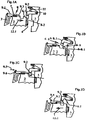
Fig.1A-D Ansichten eines Handfeuerlöschers in einer Sequenz von Einbaubewegungen -
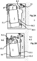
Fig.2A-B Ansichten eines Handfeuerlöschers in einer Sequenz von schwenkenden Einbaubewegungen -
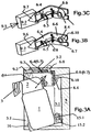
Fig.3A Ansicht eines Handfeuerlöschers in einer schwenkenden Einbaubewegung -
Fig.3B-C Detail der Schnappfalle nachFig.3A - Die Beschreibung gilt in gleicher Weise für alle Figuren, sofern nicht bezüglich einer der Figuren eine Besonderheit hervorgehoben wird. Für gleichartige und insbesondere funktionsgleiche Teile werden identische Bezugszeichen verwandt. Dabei sind in den
Figuren 1A bis 1C und2A bis 2B die Ausgangspositionen des Handfeuerlöschers mit durchgezogenen Linien und die Endpositionen mit gestrichelten Linie dargestellt. - Der Handfeuerlöscher besteht aus dem Behälter 1 und dem Armaturenkopf 2. Der Behälter dient zur Aufnahme des flüssigen oder pulverförmigen Löschmittels. Der Armaturenkopf 2 enthält im wesentlichen die druckdichte Verschraubung des Behälters 1, das Auslaßventil, einen Ventilhebel zur Bedienung des Handfeuerlöschers. In den Figuren ist sichtbar nur der Handgriff 3 zum Tragen des Handfeuerlöscher sowie die Auslassdüse 4, die dem Auslass des Löschmittels im Brandfall dient und die nach außen als Kreis-zylindrischer Vorsprung erscheint.
- Wegen weiterer Einzelheiten der Ausgestaltung und Funktion eines solchen Handfeuerlöschers und seiner Einzelteile wird zum Beispiel auf wie
DE 102010015454 B4 verwiesen. - Der Handfeuerlöscher soll in dem Fahrgastraum eines Kraftfahrzeugs befestigt werden. Hierzu ist in den Figuren die Haltewand 5 zu sehen. Es kann sich dabei um eine Wand im Inneren des Kraftfahrzeugs handeln, welche zur Umgrenzung des Innenraums, oder zum Beispiel zum Aufbau eines Sitzes dient, zum Beispiel eine Blechplatte unter einem der Vordersitze, insbesondere Fahrersitz.
- Die Haltewand 5 kann jedoch auch ein separates Bauteil sein, welches an eine Wandlung des Kraftfahrzeug-Innenraums angeschraubt oder in sonstiger Weise dort befestigt wird. Das hat den Vorteil, dass die Haltewand mit weiteren Funktionteilen zur Aufnahme und Befestigung des Handfeuerlöschers versehen werden kann, wie es nachfolgend anhand der
Figuren 2A, 2B ,3A beschrieben wird. - In allen Ausführungsbeispielen dient zur Befestigung des Handfeuerlöschers an der Haltewand 5 eine Schnappfalle 6, bestehend aus Greifelement 6.1 und Ausnehmung 6.2. Zur Betätigung der Schnappfalle 6 dienen eine Spreizeinrichtung 8 und eine Ausschiebeinrichtung 9.
- In
Figur 1 ist das Greifelement 6.1 der Schnappfalle 6 ein Schwenkhebel, welcher in einem Gelenk 10 an der Haltewand 5 schwenkbar gelagert und in seiner unteren definierten Position -in denFiguren 1A, 1C ersichtlich- durch eine Feder 11 gehalten und festgelegt ist. Diese Position wird als die Greifstellung 13 bezeichnet. - In
Figur 1 ist von dem Handfeuerlöscher lediglich der Armaturenkopf und auch dieser nur teilweise dargestellt. Es fehlt in derFigur 1 auch die Führungseinrichtung , durch welche der Handfeuerlöscher auf einer definierten Einbaubahn mit der definierten Einbaubewegung in seine Halteposition geführt wird. Diese Führungseinrichtung wird an Hand der weiteren Figuren beschrieben. InFigur 1 besteht die Spreizeinrichtung 8 aus einer Abschrägung 8.1 und einer Abschrägung 8.2, einerseits oben -in Einbaubewegung- vorn an dem Armaturenkopf 2 des Handfeuerlöschers und andererseits -der Einbaubewegung entgegen- an dem freien unteren Ende des Schwenkhebels, welcher als Greifelement 6.1 dient. - In
Figur 1 ist erkennbar, dass zum Einbau in seine Halteposition der Handfeuerlöscher durch die nicht dargestellte Führungseinrichtung in einer vorgegebenen Längs- und Drehlage auf einer vorgegebenen Einbaubahn und mit einer vorgegebenen Einbaubewegung zu dem -in diesem Fall- als Spreizeinrichtung dienenden unteren Ende des Greifelementes 6.1 geführt wird. Bei weiterer Einbaubewegung in Richtung des Pfeiles 12.1 greift die Abschrägung 8.1 an der Vorderseite des Armaturenkopfes unter die Abschrägung 8.2 des freien Endes des Greifelementes 6.1 und hebt dieses dadurch gegen die Federkraft 11 hoch. Diese Situation ist inFigur 1B dargestellt. -
Figur 1C zeigt, dass das Greifelement nunmehr in die Ausnehmung 6.2 eingefallen ist und dadurch dem Handfeuerlöscher in seiner inFigur 1C dargestellten Halteposition festhält. - Das Lösen der Schnappfalle 6 wird anhand von
Figur 1D der Bildsequenz beschrieben. Hierbei tritt die Ausschiebeinrichtung 9 in Funktion. Sie besteht aus dem Kulissenschieber 9.1 und dem Kulissenstein 9.2. Der Kulissenstein ist an dem Gleitelement 6.1 befestigt und hier als seitlich auskragender Zapfen an das Gleitelement angesetzt. In der inFigur 1C ersichtlichen Greifstellung liegt der Kulissenstein gerade über der Ausnehmung 6.2. - Der Kulissenschieber 9.1 ist in Richtung des Gelenks 10 des Gleitelementes 6.1 gerad geführt und gegen die Kraft der Feder 7 in dem Sinne beweglich, dass seine Kulissenflanke 9.3 am vorderen Ende des Kulissenschiebers den Kulissenstein 9.2 untergreift und beim Weiterschieben den Kulissenstein und damit das Greifelement 6.1 in einer Schwenkbewegung gegen die Kraft der Feder 11 hoch hebt. Dadurch wird das Greifelement aus der Ausnehmung 6.2 herausgehoben, so dass der Handfeuerlöscher in Richtung des Pfeils 12.2 wieder aus seiner Halteposition heraus genommen werden kann. In dem gezeigten Beispiel ist der Kulissenschieber auf der Oberseite des Armaturenkopfes gerade geführt, so dass sich auch die Feder 7 an dem Armaturenkopf abstürzt und dabei den Handgriff 9.4 des Kulissenschiebers 9.1 gegen einen Anschlag 9.6 drückt, welcher an dem Armaturenkopf befestigt ist.
- Der Bediener, der in den Handgriff 3 hineingreift, kann dabei mit dem Daumen auch den Handgriff 9.4 des Kulissenschieber es 9.1 hintergreifen und diesen in Richtung Pfeil 9.5 im Sinne des Lösens des Greifelementes 6.1 verschieben.
- Es wurde bereits darauf hingewiesen, dass der Handfeuerlöscher zum Festlegen in seiner Halteposition auch an seinem unteren Ende, das heißt im Bereich des Bodens eine derartige Schnappfalle aufweisen kann. In diesem Falle wird der Handfeuerlöscher bezüglich seiner Längsachse 14 parallel zu sich selbst gerad verschoben und so geführt, dass beide Schnappfallen simultan einfallen.
- Das Ausführungsbeispiel nach der Bildsequenz der
Figuren 2A, 2B führt dagegen eine schwenkende Einbaubewegung in einer definierten Führungsebene aus. Die Schnappfalle ist bei diesem Ausführungsbeispiel ausgebildet wie zuvor geschildert. - Der Handfeuerlöscher weist jedoch im Bereich seines Bodens eine Schwenkgelenkverbindung 15 auf.
- Diese Schwenkgelenkverbindung 15 besteht aus einem Zapfen 15.1 und einer Einlassöse 15.2, welche einerseits an der Haltewand 5 und andererseits an dem Behälter 1 angebracht sind. Zur Anbringung des Zapfens beziehungsweise der Einlassöse an dem Behälter 1 dient in dem Ausführungsbeispiel ein Mantel 16, welcher über den Boden des Behälters gestülpt wird und sodann den Behälter und einen Teil des zylindrischen Mantels schlupf-frei umfasst. In dem Ausführungsbeispiel ist die Einlassöse an diesen Mantel 15 als achs-paralleles Loch angebracht, welches zum Einbau des Handfeuerlöschers an die Haltewand 5 über den Zapfen gestülpt wird. Dies geschickt - wie
Figur 2A zeigt- in einer Schräglage des Handfeuerlöschers relativ zu seiner Halteposition, wobei jedoch der Handfeuerlöscher durch eine an dich Haltewand 5 angeformte Führungswand 17 abgestürzt wird. Die Führungswand 17 ist parallel zu der vorgesehenen Einbaubewegung derart ausgerichtet, dass durch eine Schwenkbewegung des Handfeuerlöschers in Richtung des Pfeiles 12.1 um die Schwenkgelenkverbindung die Ausnehmung 6.2 der Schnappfalle sechs in den Wirkungsbereich des Greifelementes 6.1 gerät, wie dies inFigur 2B dargestellt ist. - Die
Figur 3A zeigt ebenfalls einen Handfeuerlöscher, der durch eine Schwenk-Bewegung in seine Halteposition gelangt. Dafür ist die Schwenkgelenkverbindung -wie zuvor geschildert- ausgebildet. - Die Besonderheit besteht hier in der Ausbildung Schnappfalle 6 und des Spreizelementes 8, die im Detail in den
Figuren 3B und 3C dargestellt sind. Dabei sind dieFiguren 3B und 3C Ansichten in Richtung des Pfeiles bei ausgebautem Handfeuerlöscher. - Das Greifelement der Schnappfalle besteht hier aus 2 relativ zu einander beweglichen Blättern 6.4 6.5. Diese sind befestigt an je einem rechtwinklig abgeknickten Traghebel 6.6 und 6.7. Jeder der Traghebel ist um ein -hiergemeinsames Gelenk 6.8 schwenkbar. Die Traghebel sind durch Feder 11 derart belastet, daß die Blätter 6.4 und 6.7 in ihrer Ruhestellung, d.h. Greifstellung vor einander stoßen und dabei eine kreisförmige Fangöffnung 6.10 bilden.
- Die Spreizeinrichtung wird hier an einem kegeligen Dorn 8.4 gebildet, dessen Spitze in die Fangöffnung paßt und die Blätter auseinander drückt, wenn der Dorn weiter in die Fangöffnung 6.10 gestoßen wird.
- In den
Figuren 3B,3C ist ein solcher Dorn gezeigt, der Anschaulichkeit halber jedoch von der falschen Seite in die Fangöffnung 6.10 stoßend. - Es sei erwähnt, dass sich die Blätter in ihrer federbelasteten Halteposition auch scherenartig überlappen und dabei die Fangöffnung 6.10 als Aufspreizöffnung freilassen können. Das hängt von ihrer Schwenklagerung in dem Gelenk 6.8 ab. Als Dorn fungiert vorzugsweise die Auslaßdüse 4, die zu diesem Zweck als auskragender Haltezapfen ausgebildet wird, an ihrem freien Mündungsende die konische Spreizspitze 8.3 aufweist und mit der Fangöffnung 6.10 der Schnappfalle dadurch zusammenwirkt, dass der Spreizspitze als Ausnehmung eine Einschnürung/ Ringnut 8.4 mit radialen Flanken folgt. Der Durchmesser dieser Ringnut entspricht dem Durchmesser der Fangöffnung 6.10 und die Breite der Ringnut der Dicke der Blätter 6.4, 6.5. Dies ist aus
Fig.3A ersichtlich. - Von besonderem Vorteil ist bei diesem Ausführungsbeispiel, daßdie beweglichen Teile der Schnappfalle und der Ausschiebeeinrichtung nicht an dem Handfeuerlöscher angebracht sind, sein Gewicht daher nicht erhöhen und auch weniger der Gefahr einer Beschädigung ausgesetzt sind.
-
Fig.3A zeigt: Dazu besitzt die Haltewand 5 einen Vorsprung 5.2, welcher die Halteposition des Handfeuerlöschers überragt. An diesem Vorsprung sind die Traghebel 6.6, 6.7 in dem Gelenk 6.8 parallel zur Oberseite des Armaturenkopf es 2 gelagert. Die Blätter, die demgegenüber um 90° abgeknickt sind, weisen mit ihrer Fangöffnung 6.10 also in Richtung der Spreizspitze 8.3, welche sich in Richtung des Pfeils bei der Schwenkbewegung nähert. Gegen die Kraft der Feder 11 werden also die Blätter aus einander gespreizt. Und sie schnappen unter der Kraft der Feder wieder in ihre Fangstellung zurück, wenn die Ringnut 6.3 der Auslassdüse in den Bereich der Blätter gelangt. - Zum Öffnen der Schnappfalle dient der Kulissenschieber 9.1. Dieser ist an dem Vorsprung 5.2 gleitend geführt. Er übergreift mit einer Dreieck-förmigen Ausnehmung 9.6 die Enden der der Targhebel 6.4,6.5, welche von dem Gelenk 6.8 aus in Richtung des Endes des Vorsprungs 5.2 auskragen. Wenn die Blätter in ihrer Fangstellung liegen, streben die Enden der Traghebel auseinander und und dadurch gleiten die Enden der Traghebel an den Flanken der dreieckigen Ausnehmung 9.6 ab. Dabei wirkt die Feder 11 über die Enden der Traghebel und die Flanken der dreieckigen Ausnehmung auf den Kulissenstein ein und drückt den Kulissenschieber 9.1 zum Ende des Vorsprungs. Dadurch gelangt der Kulissenschieber 9.1 in den Griffbereich eines Bedieners, der in den Handgriff 3 eingreift. Der Bediener kann nunmehr den Kulissenschieber 9.1 gegen die Kraft der Feder 11 verschieben. Dadurch werden die Enden der Traghebel zu und die Blätter aus einander gedrückt und die Fangöffnung 6.10 soweit aufgeweitet, daß die Auslassdüse und damit der Handfeuerlöscher freigegeben wird.
- Es wird hervorgehoben, daß in allen Fällen als Führungseinrichtung nicht nur ein mit der Haltewand verbundenes Bauteil sondern auch die Schwenkgelenkverbindung zwischen Handfeuerlöscher und Haltewand in Betracht kommt und fungieren kann.
- Voraussetzung ist, dass die Schwenkgelenkverbindung den Handfeuerlöscher in der durch die Schnappfalle vorgegebenen Schwenkebene ohne unzulässiges Spiel aufnimmt und die Schwenkbewegung in der durch die Schnappfalle vorgegebenen Toleranz so sicher führt, dass das Greifelement und die Ausnehmung in der Halteposition des Handfeuerlöschers in Wirkverbindung gelangen.
-
- Behälter 1
- Armaturenkopf 2
- Handgriff 3
- Auslassdüse 4,
- Haltewand 5
- Führungswand 5.1
- Vorsprung 5.2 der Haltewand 5
- Schnappfalle 6
- Greifelement 6.1
- Ausnehmung 6.2
- Ringnut 6.3
- Blatt 6.4
- Blatt 6.5.
- Traghebel 6.6
- Traghebel 6.7.
- Gelenk 6.8
- Fangöffnung 6.10
7 - Spreizeinrichtung 8
- Abschrägung 8.1
- Abschrägung 8.2
- Spreizspitze 8.3
- Ausschiebeinrichtung 9.
- Kulissenschieber 9.1
- Kulissenstein 9.2
- Kulissenflanke 9.3
- Handgriff 9.4
- Anschlag 9.6
- Pfeil Richtung 9.5
- Ausnehmung 9.6
- Gelenk 10
- Feder 11
- Pfeil 12.1 in Einbaurichtung
- Pfeil 12.2gegen die Einbaurichtung
- Greifstellung 13
- Längsachse 14
- Schwenkgelenkverbindung 15
- Zapfen 15.1
- Einlassöse 15.2
- Mantel 16
Claims (10)
- Handfeuerlöscher
mit einem zylindrischen Behälter für das Löschmittel,
mit einem Armaturenkopf, der einen Behälterverschluss, ein Auslassventil, einen Ventilhebel sowie einen Handgriff aufweist und
mit einer durch Handhabe lösbaren Halteeinrichtung zur Befestigung des Handfeuerlöschers in seiner Halteposition an einer Haltewand im Innenraum eines Kfz,
dadurch gekennzeichnet, dass
die Halteeinrichtung die Paarung einer formschlüssigen Schnappfalle ist, welche aus• einem beweglich geführten Greifelement an dem einen von Handfeuerlöscher bzw. Haltewand und• einer Ausnehmung an dem anderen von Handfeuerlöscher bzw. Haltewand besteht,dass der Handfeuerlöscher durch eine Führungseinrichtung mit vorgegebener Einbaubewegung in seine Halteposition bewegbar ist,
wobei das Greifelement durch Federkraft dauernd in einer Greifstellung gehalten ist,
dass allein durch die und bei der Einbaubewegung in die Halteposition eine Spreizeinrichtung mit dem Greifelement zum Ausheben aus seiner Greifstellung zusammenwirkt, wobei das Greifelement gegen die einwirkende Federkraft aus seiner Greifstellung gehoben und wieder zur Bewegung in die Greifstellung freigegeben wird, wenn der Handfeuerlöscher seine Halteposition erreicht hat, dass das Greifelement und die Ausnehmung derart zusammenwirken,
dass in der Halteposition des Handfeuerlöschers das Greifelement in der Greifstellung formschlüssig in die Ausnehmung eingreift und den Handfeuerlöscher in der Halteposition an der Haltewand festklemmt,
dass eine durch Handhabe handbetätigte Ausschiebeinrichtung mit dem Greifelement in dem Sinne zusammenwirkt, dass das Greifelement gegen seine Federkraft aus der Greifstellung verschiebbar ist und die Ausnehmung freigibt. - Handfeuerlöscher nach Anspruch 1
dadurch gekennzeichnet, dass
Die die Paarung der formschlüssigen Schnappfalle im Bereich des einen Endes des Handfeuerlöschers liegt und
Dass die Führungseinrichtung eine Schwenkgelenkverbindung im Bereich des anderen Endes des Handfeuerlöschers ist, um welche der Handfeuerlöscher eine schwenkende Einbaubewegung in einer vorbestimmten Schwenkebene seiner Längsachse ausführt,
wobei die Schwenkgelenkverbindung aus einem in der Schwenkebene liegender in Richtung der Schnappfalle auskragender Einsteckzapfen an dem einen von Handfeuerlöscher bzw. Haltewand und
einer in Richtung der Schnappfalle offenen, dem Einsteckzapfen angepassten Eingrifföse an dem anderen von Handfeuerlöscher bzw. Haltewand besteht, und die Schwenkgelenkverbindung durch Einstecken des Einsteckzapfens in die Eingrifföse herstellbar ist. - Handfeuerlöscher nach Anspruch 1
dadurch gekennzeichnet, dass
Die Schnappfalle im Bereich des Armaturenkopfes des Handfeuerlöschers und die Handhabe zur Lösung der Halteeinrichtung an dem Armaturenkopf angebracht ist. - Handfeuerlöscher nach Anspruch 1
dadurch gekennzeichnet, dass
Die Schwenkgelenkverbindung im Bereich des Bodens des Handfeuerlöschers angebracht ist. - Handfeuerlöscher nach Anspruch 1
dadurch gekennzeichnet, dass
im Bereich des Bodens des Handfeuerlöschers achsparallele Führungspaarungen in Form von Riefen/Wulst-Verbindungen oder Nut/Feder-Verbindungen angebracht sind zur Drehsicherung des Behälters und Führung des Handfeuerlöschers beim Einstecken in die Schwenkgelenkverbindung . - Handfeuerlöscher nach Anspruch 1
dadurch gekennzeichnet, dass
Das eine Teil der Schwenkgelenkverbindung -Einsteckzapfen oder Eingrifföse - an einem Tragring/Mantel angebracht ist, welcher über den Boden auf das untere Ende des Zylindermantels des Behälters stülpbar ist. - Handfeuerlöscher nach Anspruch 1
dadurch gekennzeichnet, dass
Die Paarung der Schnappfalle und/oder die Paarung der Schwenkgelenkverbindung auf den Handfeuerlöscher einerseits und einen Halterücken andererseits verteilt angebracht sind, welcher an der Haltewand des KFZs befestigt wird. - Handfeuerlöscher nach Anspruch 1
dadurch gekennzeichnet, dass
Die Paarung der Schnappfalle und/oder die Paarung der Schwenkgelenkverbindung auf den Handfeuerlöscher einerseits und eine Haltewand des KFZ andererseits verteilt angebracht sind, ohne Zwischenschaltung eines von der Haltewand lösbaren Halterücken Halterückens. - Handfeuerlöscher nach Anspruch 1
dadurch gekennzeichnet, dass
Das Greifelement der Schnappfalle aus 2 relativ zu einander beweglichen Blättern besteht, welche sich in ihrer federbelasteten Halteposition überlappen oder vor einanderstoßen und dabei eine Aufspreizöffnung freilassen,
dass die Ausnehmung eine ringförmige Einschnürung an einem auskragenden Haltezapfen ist, deren Durchmesser dem Durchmesser der Aufspreizöffnung im wesentlcchen entspricht,
und dass der Haltezapfen eine konische Spitze aufweist, welche im Durchmesser kleiner als die Aufspreizöffnung ist. - Handfeuerlöscher nach Anspruch 1
dadurch gekennzeichnet, dass
Blättern relativ zu einander scherenartig oder gouillotineartig beweglich und mit Betätigungshebeln verbunden sind, welche mit der Handhabe an dem Armaturenkopf zusammenwirken im Sinne der Lösung der Schnappfalle zur Entnahme des Handfeuerlöschers.
Es wird hervorgehoben, daß in allen Fällen als Führungseinrichtung nicht nur ein mit der Haltewand verbundenes Bauteil sondern auch die Schwenkgelenkverbindung zwischen Handfeuerlöscher und Haltewand in Betracht kommt und fungieren kann.
Voraussetzung ist, dass die Schwenkgelenkverbindung den Handfeuerlöscher in der durch die Schnappfalle vorgegebenen Schwenkebene ohne unzulässiges Spiel aufnimmt und die Schwenkbewegungen in der durch die Schnappfalle vorgegebenen Tolreanz so sicher führt, dass das Greifelement und die Ausnehmung in der Haltposition des Handfeuerlöschers in Wirkverbindung gelangen.
Applications Claiming Priority (1)
| Application Number | Priority Date | Filing Date | Title |
|---|---|---|---|
| DE102017000688 | 2017-01-26 |
Publications (2)
| Publication Number | Publication Date |
|---|---|
| EP3354321A1 true EP3354321A1 (de) | 2018-08-01 |
| EP3354321B1 EP3354321B1 (de) | 2023-12-20 |
Family
ID=61022096
Family Applications (1)
| Application Number | Title | Priority Date | Filing Date |
|---|---|---|---|
| EP18000017.6A Active EP3354321B1 (de) | 2017-01-26 | 2018-01-10 | Handfeuerlöscher |
Country Status (2)
| Country | Link |
|---|---|
| EP (1) | EP3354321B1 (de) |
| DE (1) | DE102018000130A1 (de) |
Cited By (4)
| Publication number | Priority date | Publication date | Assignee | Title |
|---|---|---|---|---|
| CN109675230A (zh) * | 2019-03-11 | 2019-04-26 | 中建新疆建工集团第一建筑工程有限公司 | 建筑工地用手持灭火器停靠坞 |
| CN113941107A (zh) * | 2021-10-26 | 2022-01-18 | 珠海城市职业技术学院 | 一种应急求生装置 |
| CN114768160A (zh) * | 2022-04-12 | 2022-07-22 | 江苏格罗那消防器材有限公司 | 一种手提式灭火器状态监控系统及方法 |
| CN115445117A (zh) * | 2022-08-25 | 2022-12-09 | 南京金龙客车制造有限公司 | 一种客车车内隐藏式灭火器安装系统 |
Families Citing this family (1)
| Publication number | Priority date | Publication date | Assignee | Title |
|---|---|---|---|---|
| DE102024126044A1 (de) | 2023-09-20 | 2025-03-20 | Feuerschutz Jockel Gmbh & Co. Kg | Handfeuerlöschereinrichtung |
Citations (3)
| Publication number | Priority date | Publication date | Assignee | Title |
|---|---|---|---|---|
| GB263037A (en) * | 1926-06-18 | 1926-12-23 | Albert Brown Phister | Fire extinguishers and systems of installing same |
| GB1089185A (en) * | 1964-08-17 | 1967-11-01 | Reynolds Tube Company Ltd | Containers for liquified or compressed gases |
| US3889758A (en) * | 1971-04-05 | 1975-06-17 | Byron G Dunn | Hand operable fire extinguisher |
Family Cites Families (2)
| Publication number | Priority date | Publication date | Assignee | Title |
|---|---|---|---|---|
| DE102010015454B4 (de) | 2009-04-18 | 2012-02-09 | Feuerschutz Jockel Gmbh & Co. Kg | Handfeuerlöscher |
| DE102010047024B4 (de) | 2009-11-21 | 2014-12-24 | Feuerschutz Jockel Gmbh & Co. Kg | Handfeuerlöscher |
-
2018
- 2018-01-10 DE DE102018000130.0A patent/DE102018000130A1/de not_active Withdrawn
- 2018-01-10 EP EP18000017.6A patent/EP3354321B1/de active Active
Patent Citations (3)
| Publication number | Priority date | Publication date | Assignee | Title |
|---|---|---|---|---|
| GB263037A (en) * | 1926-06-18 | 1926-12-23 | Albert Brown Phister | Fire extinguishers and systems of installing same |
| GB1089185A (en) * | 1964-08-17 | 1967-11-01 | Reynolds Tube Company Ltd | Containers for liquified or compressed gases |
| US3889758A (en) * | 1971-04-05 | 1975-06-17 | Byron G Dunn | Hand operable fire extinguisher |
Cited By (6)
| Publication number | Priority date | Publication date | Assignee | Title |
|---|---|---|---|---|
| CN109675230A (zh) * | 2019-03-11 | 2019-04-26 | 中建新疆建工集团第一建筑工程有限公司 | 建筑工地用手持灭火器停靠坞 |
| CN109675230B (zh) * | 2019-03-11 | 2024-01-30 | 中建新疆建工集团第一建筑工程有限公司 | 建筑工地用手持灭火器停靠坞 |
| CN113941107A (zh) * | 2021-10-26 | 2022-01-18 | 珠海城市职业技术学院 | 一种应急求生装置 |
| CN114768160A (zh) * | 2022-04-12 | 2022-07-22 | 江苏格罗那消防器材有限公司 | 一种手提式灭火器状态监控系统及方法 |
| CN114768160B (zh) * | 2022-04-12 | 2022-12-13 | 江苏格罗那消防器材有限公司 | 一种手提式灭火器状态监控系统及方法 |
| CN115445117A (zh) * | 2022-08-25 | 2022-12-09 | 南京金龙客车制造有限公司 | 一种客车车内隐藏式灭火器安装系统 |
Also Published As
| Publication number | Publication date |
|---|---|
| EP3354321B1 (de) | 2023-12-20 |
| DE102018000130A1 (de) | 2018-07-26 |
Similar Documents
| Publication | Publication Date | Title |
|---|---|---|
| DE602006000674T2 (de) | Selbstverriegelnder Karabinerhaken | |
| EP3354321A1 (de) | Handfeuerlöscher | |
| WO2018041623A1 (de) | Türaussengriff für ein kraftfahrzeug | |
| DE2345593C3 (de) | Kupplungsvorrichtung | |
| DE3710049C2 (de) | ||
| DE3105951C2 (de) | Kraftwerkzeug | |
| EP3050839B1 (de) | Verschluss mit einem kniehebelspanner für ein flurförderzeug | |
| DE3239948C1 (de) | Vorrichtung zum Betaetigen eines Schieberverschlusses | |
| DE2043780C3 (de) | Innenverriegelungseinrichtungfür einen Kraftfahrzeug-TürverschluB | |
| EP1440448A1 (de) | Tür-vorrichtung für einen isolator | |
| EP0279929A2 (de) | Absturzsicherung | |
| DE10127425B4 (de) | Haltevorrichtung für bewegliche Verschlusselemente | |
| DE102013016069A1 (de) | Türgriff | |
| DE102018123734B4 (de) | Vorrichtung, System und Verfahren zum Sichern einer Last in einem Fahrzeug | |
| DE2457017C3 (de) | Schaltvorrichtung für ein Wechselgetriebe von Lastkraftwagen mit kippbarem Fahrerhaus | |
| DE8105158U1 (de) | "hakenverschluss fuer bordwaende von nutzfahrzeugen" | |
| DE102017124258A1 (de) | Halbautomatische einstellbare Zange | |
| DE2723073C2 (de) | ||
| EP3467324A2 (de) | Verriegelungsvorrichtung zum dichten verbinden eines schlauches mit einem flugobjekt | |
| EP3399106A1 (de) | Schnellwechselkupplung zum befestigen eines anbaugeräts | |
| DE619674C (de) | Vorrichtung an Tueren von Kraftfahrzeugen zum OEffnen der Tuer von einer entfernten Stelle durch den Fuehrer oder einen Fahrgast | |
| EP3375662A1 (de) | Ratschenspannvorrichtung | |
| EP1400644A1 (de) | Fanghakeneinrichtung für eine Fronthaube eines Kraftfahrzeugs | |
| EP0901916A1 (de) | Anhängekupplung für ein Zugfahrzeug | |
| DE1944274A1 (de) | Loesbares Koppel |
Legal Events
| Date | Code | Title | Description |
|---|---|---|---|
| PUAI | Public reference made under article 153(3) epc to a published international application that has entered the european phase |
Free format text: ORIGINAL CODE: 0009012 |
|
| STAA | Information on the status of an ep patent application or granted ep patent |
Free format text: STATUS: THE APPLICATION HAS BEEN PUBLISHED |
|
| AK | Designated contracting states |
Kind code of ref document: A1 Designated state(s): AL AT BE BG CH CY CZ DE DK EE ES FI FR GB GR HR HU IE IS IT LI LT LU LV MC MK MT NL NO PL PT RO RS SE SI SK SM TR |
|
| AX | Request for extension of the european patent |
Extension state: BA ME |
|
| STAA | Information on the status of an ep patent application or granted ep patent |
Free format text: STATUS: REQUEST FOR EXAMINATION WAS MADE |
|
| 17P | Request for examination filed |
Effective date: 20180822 |
|
| GRAP | Despatch of communication of intention to grant a patent |
Free format text: ORIGINAL CODE: EPIDOSNIGR1 |
|
| STAA | Information on the status of an ep patent application or granted ep patent |
Free format text: STATUS: GRANT OF PATENT IS INTENDED |
|
| INTG | Intention to grant announced |
Effective date: 20230718 |
|
| GRAS | Grant fee paid |
Free format text: ORIGINAL CODE: EPIDOSNIGR3 |
|
| GRAA | (expected) grant |
Free format text: ORIGINAL CODE: 0009210 |
|
| STAA | Information on the status of an ep patent application or granted ep patent |
Free format text: STATUS: THE PATENT HAS BEEN GRANTED |
|
| AK | Designated contracting states |
Kind code of ref document: B1 Designated state(s): AL AT BE BG CH CY CZ DE DK EE ES FI FR GB GR HR HU IE IS IT LI LT LU LV MC MK MT NL NO PL PT RO RS SE SI SK SM TR |
|
| REG | Reference to a national code |
Ref country code: GB Ref legal event code: FG4D Free format text: NOT ENGLISH |
|
| REG | Reference to a national code |
Ref country code: DE Ref legal event code: R096 Ref document number: 502018013826 Country of ref document: DE |
|
| REG | Reference to a national code |
Ref country code: CH Ref legal event code: EP |
|
| REG | Reference to a national code |
Ref country code: IE Ref legal event code: FG4D Free format text: LANGUAGE OF EP DOCUMENT: GERMAN |
|
| PG25 | Lapsed in a contracting state [announced via postgrant information from national office to epo] |
Ref country code: GR Free format text: LAPSE BECAUSE OF FAILURE TO SUBMIT A TRANSLATION OF THE DESCRIPTION OR TO PAY THE FEE WITHIN THE PRESCRIBED TIME-LIMIT Effective date: 20240321 |
|
| REG | Reference to a national code |
Ref country code: LT Ref legal event code: MG9D |
|
| PG25 | Lapsed in a contracting state [announced via postgrant information from national office to epo] |
Ref country code: LT Free format text: LAPSE BECAUSE OF FAILURE TO SUBMIT A TRANSLATION OF THE DESCRIPTION OR TO PAY THE FEE WITHIN THE PRESCRIBED TIME-LIMIT Effective date: 20231220 |
|
| P01 | Opt-out of the competence of the unified patent court (upc) registered |
Effective date: 20240312 |
|
| REG | Reference to a national code |
Ref country code: NL Ref legal event code: MP Effective date: 20231220 |
|
| PG25 | Lapsed in a contracting state [announced via postgrant information from national office to epo] |
Ref country code: ES Free format text: LAPSE BECAUSE OF FAILURE TO SUBMIT A TRANSLATION OF THE DESCRIPTION OR TO PAY THE FEE WITHIN THE PRESCRIBED TIME-LIMIT Effective date: 20231220 |
|
| PG25 | Lapsed in a contracting state [announced via postgrant information from national office to epo] |
Ref country code: LT Free format text: LAPSE BECAUSE OF FAILURE TO SUBMIT A TRANSLATION OF THE DESCRIPTION OR TO PAY THE FEE WITHIN THE PRESCRIBED TIME-LIMIT Effective date: 20231220 Ref country code: GR Free format text: LAPSE BECAUSE OF FAILURE TO SUBMIT A TRANSLATION OF THE DESCRIPTION OR TO PAY THE FEE WITHIN THE PRESCRIBED TIME-LIMIT Effective date: 20240321 Ref country code: FI Free format text: LAPSE BECAUSE OF FAILURE TO SUBMIT A TRANSLATION OF THE DESCRIPTION OR TO PAY THE FEE WITHIN THE PRESCRIBED TIME-LIMIT Effective date: 20231220 Ref country code: ES Free format text: LAPSE BECAUSE OF FAILURE TO SUBMIT A TRANSLATION OF THE DESCRIPTION OR TO PAY THE FEE WITHIN THE PRESCRIBED TIME-LIMIT Effective date: 20231220 Ref country code: BG Free format text: LAPSE BECAUSE OF FAILURE TO SUBMIT A TRANSLATION OF THE DESCRIPTION OR TO PAY THE FEE WITHIN THE PRESCRIBED TIME-LIMIT Effective date: 20240320 |
|
| PG25 | Lapsed in a contracting state [announced via postgrant information from national office to epo] |
Ref country code: NL Free format text: LAPSE BECAUSE OF FAILURE TO SUBMIT A TRANSLATION OF THE DESCRIPTION OR TO PAY THE FEE WITHIN THE PRESCRIBED TIME-LIMIT Effective date: 20231220 |
|
| PG25 | Lapsed in a contracting state [announced via postgrant information from national office to epo] |
Ref country code: SE Free format text: LAPSE BECAUSE OF FAILURE TO SUBMIT A TRANSLATION OF THE DESCRIPTION OR TO PAY THE FEE WITHIN THE PRESCRIBED TIME-LIMIT Effective date: 20231220 Ref country code: RS Free format text: LAPSE BECAUSE OF FAILURE TO SUBMIT A TRANSLATION OF THE DESCRIPTION OR TO PAY THE FEE WITHIN THE PRESCRIBED TIME-LIMIT Effective date: 20231220 Ref country code: NO Free format text: LAPSE BECAUSE OF FAILURE TO SUBMIT A TRANSLATION OF THE DESCRIPTION OR TO PAY THE FEE WITHIN THE PRESCRIBED TIME-LIMIT Effective date: 20240320 Ref country code: NL Free format text: LAPSE BECAUSE OF FAILURE TO SUBMIT A TRANSLATION OF THE DESCRIPTION OR TO PAY THE FEE WITHIN THE PRESCRIBED TIME-LIMIT Effective date: 20231220 Ref country code: LV Free format text: LAPSE BECAUSE OF FAILURE TO SUBMIT A TRANSLATION OF THE DESCRIPTION OR TO PAY THE FEE WITHIN THE PRESCRIBED TIME-LIMIT Effective date: 20231220 Ref country code: HR Free format text: LAPSE BECAUSE OF FAILURE TO SUBMIT A TRANSLATION OF THE DESCRIPTION OR TO PAY THE FEE WITHIN THE PRESCRIBED TIME-LIMIT Effective date: 20231220 |
|
| PG25 | Lapsed in a contracting state [announced via postgrant information from national office to epo] |
Ref country code: IS Free format text: LAPSE BECAUSE OF FAILURE TO SUBMIT A TRANSLATION OF THE DESCRIPTION OR TO PAY THE FEE WITHIN THE PRESCRIBED TIME-LIMIT Effective date: 20240420 |
|
| PG25 | Lapsed in a contracting state [announced via postgrant information from national office to epo] |
Ref country code: CZ Free format text: LAPSE BECAUSE OF FAILURE TO SUBMIT A TRANSLATION OF THE DESCRIPTION OR TO PAY THE FEE WITHIN THE PRESCRIBED TIME-LIMIT Effective date: 20231220 |
|
| PG25 | Lapsed in a contracting state [announced via postgrant information from national office to epo] |
Ref country code: SK Free format text: LAPSE BECAUSE OF FAILURE TO SUBMIT A TRANSLATION OF THE DESCRIPTION OR TO PAY THE FEE WITHIN THE PRESCRIBED TIME-LIMIT Effective date: 20231220 |
|
| PG25 | Lapsed in a contracting state [announced via postgrant information from national office to epo] |
Ref country code: SM Free format text: LAPSE BECAUSE OF FAILURE TO SUBMIT A TRANSLATION OF THE DESCRIPTION OR TO PAY THE FEE WITHIN THE PRESCRIBED TIME-LIMIT Effective date: 20231220 Ref country code: SK Free format text: LAPSE BECAUSE OF FAILURE TO SUBMIT A TRANSLATION OF THE DESCRIPTION OR TO PAY THE FEE WITHIN THE PRESCRIBED TIME-LIMIT Effective date: 20231220 Ref country code: RO Free format text: LAPSE BECAUSE OF FAILURE TO SUBMIT A TRANSLATION OF THE DESCRIPTION OR TO PAY THE FEE WITHIN THE PRESCRIBED TIME-LIMIT Effective date: 20231220 Ref country code: IT Free format text: LAPSE BECAUSE OF FAILURE TO SUBMIT A TRANSLATION OF THE DESCRIPTION OR TO PAY THE FEE WITHIN THE PRESCRIBED TIME-LIMIT Effective date: 20231220 Ref country code: IS Free format text: LAPSE BECAUSE OF FAILURE TO SUBMIT A TRANSLATION OF THE DESCRIPTION OR TO PAY THE FEE WITHIN THE PRESCRIBED TIME-LIMIT Effective date: 20240420 Ref country code: EE Free format text: LAPSE BECAUSE OF FAILURE TO SUBMIT A TRANSLATION OF THE DESCRIPTION OR TO PAY THE FEE WITHIN THE PRESCRIBED TIME-LIMIT Effective date: 20231220 Ref country code: CZ Free format text: LAPSE BECAUSE OF FAILURE TO SUBMIT A TRANSLATION OF THE DESCRIPTION OR TO PAY THE FEE WITHIN THE PRESCRIBED TIME-LIMIT Effective date: 20231220 |
|
| PG25 | Lapsed in a contracting state [announced via postgrant information from national office to epo] |
Ref country code: PL Free format text: LAPSE BECAUSE OF FAILURE TO SUBMIT A TRANSLATION OF THE DESCRIPTION OR TO PAY THE FEE WITHIN THE PRESCRIBED TIME-LIMIT Effective date: 20231220 Ref country code: PT Free format text: LAPSE BECAUSE OF FAILURE TO SUBMIT A TRANSLATION OF THE DESCRIPTION OR TO PAY THE FEE WITHIN THE PRESCRIBED TIME-LIMIT Effective date: 20240422 |
|
| PG25 | Lapsed in a contracting state [announced via postgrant information from national office to epo] |
Ref country code: PT Free format text: LAPSE BECAUSE OF FAILURE TO SUBMIT A TRANSLATION OF THE DESCRIPTION OR TO PAY THE FEE WITHIN THE PRESCRIBED TIME-LIMIT Effective date: 20240422 Ref country code: PL Free format text: LAPSE BECAUSE OF FAILURE TO SUBMIT A TRANSLATION OF THE DESCRIPTION OR TO PAY THE FEE WITHIN THE PRESCRIBED TIME-LIMIT Effective date: 20231220 |
|
| REG | Reference to a national code |
Ref country code: CH Ref legal event code: PL |
|
| PG25 | Lapsed in a contracting state [announced via postgrant information from national office to epo] |
Ref country code: LU Free format text: LAPSE BECAUSE OF NON-PAYMENT OF DUE FEES Effective date: 20240110 |
|
| REG | Reference to a national code |
Ref country code: DE Ref legal event code: R097 Ref document number: 502018013826 Country of ref document: DE |
|
| PG25 | Lapsed in a contracting state [announced via postgrant information from national office to epo] |
Ref country code: LU Free format text: LAPSE BECAUSE OF NON-PAYMENT OF DUE FEES Effective date: 20240110 Ref country code: MC Free format text: LAPSE BECAUSE OF FAILURE TO SUBMIT A TRANSLATION OF THE DESCRIPTION OR TO PAY THE FEE WITHIN THE PRESCRIBED TIME-LIMIT Effective date: 20231220 |
|
| PG25 | Lapsed in a contracting state [announced via postgrant information from national office to epo] |
Ref country code: DK Free format text: LAPSE BECAUSE OF FAILURE TO SUBMIT A TRANSLATION OF THE DESCRIPTION OR TO PAY THE FEE WITHIN THE PRESCRIBED TIME-LIMIT Effective date: 20231220 |
|
| PG25 | Lapsed in a contracting state [announced via postgrant information from national office to epo] |
Ref country code: BE Free format text: LAPSE BECAUSE OF NON-PAYMENT OF DUE FEES Effective date: 20240131 |
|
| PG25 | Lapsed in a contracting state [announced via postgrant information from national office to epo] |
Ref country code: CH Free format text: LAPSE BECAUSE OF NON-PAYMENT OF DUE FEES Effective date: 20240131 |
|
| PLBE | No opposition filed within time limit |
Free format text: ORIGINAL CODE: 0009261 |
|
| STAA | Information on the status of an ep patent application or granted ep patent |
Free format text: STATUS: NO OPPOSITION FILED WITHIN TIME LIMIT |
|
| PG25 | Lapsed in a contracting state [announced via postgrant information from national office to epo] |
Ref country code: SI Free format text: LAPSE BECAUSE OF FAILURE TO SUBMIT A TRANSLATION OF THE DESCRIPTION OR TO PAY THE FEE WITHIN THE PRESCRIBED TIME-LIMIT Effective date: 20231220 |
|
| PG25 | Lapsed in a contracting state [announced via postgrant information from national office to epo] |
Ref country code: SI Free format text: LAPSE BECAUSE OF FAILURE TO SUBMIT A TRANSLATION OF THE DESCRIPTION OR TO PAY THE FEE WITHIN THE PRESCRIBED TIME-LIMIT Effective date: 20231220 Ref country code: DK Free format text: LAPSE BECAUSE OF FAILURE TO SUBMIT A TRANSLATION OF THE DESCRIPTION OR TO PAY THE FEE WITHIN THE PRESCRIBED TIME-LIMIT Effective date: 20231220 Ref country code: CH Free format text: LAPSE BECAUSE OF NON-PAYMENT OF DUE FEES Effective date: 20240131 Ref country code: BE Free format text: LAPSE BECAUSE OF NON-PAYMENT OF DUE FEES Effective date: 20240131 |
|
| REG | Reference to a national code |
Ref country code: BE Ref legal event code: MM Effective date: 20240131 |
|
| 26N | No opposition filed |
Effective date: 20240923 |
|
| GBPC | Gb: european patent ceased through non-payment of renewal fee |
Effective date: 20240320 |
|
| PG25 | Lapsed in a contracting state [announced via postgrant information from national office to epo] |
Ref country code: GB Free format text: LAPSE BECAUSE OF NON-PAYMENT OF DUE FEES Effective date: 20240320 |
|
| PG25 | Lapsed in a contracting state [announced via postgrant information from national office to epo] |
Ref country code: FR Free format text: LAPSE BECAUSE OF NON-PAYMENT OF DUE FEES Effective date: 20240220 |
|
| PG25 | Lapsed in a contracting state [announced via postgrant information from national office to epo] |
Ref country code: IE Free format text: LAPSE BECAUSE OF NON-PAYMENT OF DUE FEES Effective date: 20240110 |
|
| PG25 | Lapsed in a contracting state [announced via postgrant information from national office to epo] |
Ref country code: IE Free format text: LAPSE BECAUSE OF NON-PAYMENT OF DUE FEES Effective date: 20240110 Ref country code: GB Free format text: LAPSE BECAUSE OF NON-PAYMENT OF DUE FEES Effective date: 20240320 Ref country code: FR Free format text: LAPSE BECAUSE OF NON-PAYMENT OF DUE FEES Effective date: 20240220 |
|
| REG | Reference to a national code |
Ref country code: AT Ref legal event code: MM01 Ref document number: 1641998 Country of ref document: AT Kind code of ref document: T Effective date: 20240110 |
|
| PG25 | Lapsed in a contracting state [announced via postgrant information from national office to epo] |
Ref country code: AT Free format text: LAPSE BECAUSE OF NON-PAYMENT OF DUE FEES Effective date: 20240110 |
|
| PG25 | Lapsed in a contracting state [announced via postgrant information from national office to epo] |
Ref country code: CY Free format text: LAPSE BECAUSE OF FAILURE TO SUBMIT A TRANSLATION OF THE DESCRIPTION OR TO PAY THE FEE WITHIN THE PRESCRIBED TIME-LIMIT; INVALID AB INITIO Effective date: 20180110 |
|
| PG25 | Lapsed in a contracting state [announced via postgrant information from national office to epo] |
Ref country code: HU Free format text: LAPSE BECAUSE OF FAILURE TO SUBMIT A TRANSLATION OF THE DESCRIPTION OR TO PAY THE FEE WITHIN THE PRESCRIBED TIME-LIMIT; INVALID AB INITIO Effective date: 20180110 |
|
| PG25 | Lapsed in a contracting state [announced via postgrant information from national office to epo] |
Ref country code: TR Free format text: LAPSE BECAUSE OF FAILURE TO SUBMIT A TRANSLATION OF THE DESCRIPTION OR TO PAY THE FEE WITHIN THE PRESCRIBED TIME-LIMIT Effective date: 20231220 |
|
| PGFP | Annual fee paid to national office [announced via postgrant information from national office to epo] |
Ref country code: DE Payment date: 20251119 Year of fee payment: 9 |