EP3354167B2 - Displaysockel mit warenfach im sockel - Google Patents
Displaysockel mit warenfach im sockel Download PDFInfo
- Publication number
- EP3354167B2 EP3354167B2 EP17203462.1A EP17203462A EP3354167B2 EP 3354167 B2 EP3354167 B2 EP 3354167B2 EP 17203462 A EP17203462 A EP 17203462A EP 3354167 B2 EP3354167 B2 EP 3354167B2
- Authority
- EP
- European Patent Office
- Prior art keywords
- compartment
- display base
- shaft
- goods
- separator
- Prior art date
- Legal status (The legal status is an assumption and is not a legal conclusion. Google has not performed a legal analysis and makes no representation as to the accuracy of the status listed.)
- Active
Links
- 230000000087 stabilizing effect Effects 0.000 claims description 4
- 239000000203 mixture Substances 0.000 claims description 2
- 238000004891 communication Methods 0.000 description 3
- 238000010276 construction Methods 0.000 description 2
- 238000005516 engineering process Methods 0.000 description 2
- 238000003780 insertion Methods 0.000 description 2
- 230000037431 insertion Effects 0.000 description 2
- 238000004806 packaging method and process Methods 0.000 description 2
- 238000004080 punching Methods 0.000 description 2
- 230000006641 stabilisation Effects 0.000 description 2
- 238000011105 stabilization Methods 0.000 description 2
- 230000005484 gravity Effects 0.000 description 1
- 238000004519 manufacturing process Methods 0.000 description 1
- 239000000463 material Substances 0.000 description 1
- 239000011087 paperboard Substances 0.000 description 1
Images


Classifications
-
- A—HUMAN NECESSITIES
- A47—FURNITURE; DOMESTIC ARTICLES OR APPLIANCES; COFFEE MILLS; SPICE MILLS; SUCTION CLEANERS IN GENERAL
- A47F—SPECIAL FURNITURE, FITTINGS, OR ACCESSORIES FOR SHOPS, STOREHOUSES, BARS, RESTAURANTS OR THE LIKE; PAYING COUNTERS
- A47F5/00—Show stands, hangers, or shelves characterised by their constructional features
- A47F5/10—Adjustable or foldable or dismountable display stands
- A47F5/11—Adjustable or foldable or dismountable display stands made of cardboard, paper or the like
- A47F5/112—Adjustable or foldable or dismountable display stands made of cardboard, paper or the like hand-folded from sheet material
-
- A—HUMAN NECESSITIES
- A47—FURNITURE; DOMESTIC ARTICLES OR APPLIANCES; COFFEE MILLS; SPICE MILLS; SUCTION CLEANERS IN GENERAL
- A47F—SPECIAL FURNITURE, FITTINGS, OR ACCESSORIES FOR SHOPS, STOREHOUSES, BARS, RESTAURANTS OR THE LIKE; PAYING COUNTERS
- A47F1/00—Racks for dispensing merchandise; Containers for dispensing merchandise
- A47F1/04—Racks or containers with arrangements for dispensing articles, e.g. by means of gravity or springs
- A47F1/08—Racks or containers with arrangements for dispensing articles, e.g. by means of gravity or springs dispensing from bottom
-
- B—PERFORMING OPERATIONS; TRANSPORTING
- B65—CONVEYING; PACKING; STORING; HANDLING THIN OR FILAMENTARY MATERIAL
- B65D—CONTAINERS FOR STORAGE OR TRANSPORT OF ARTICLES OR MATERIALS, e.g. BAGS, BARRELS, BOTTLES, BOXES, CANS, CARTONS, CRATES, DRUMS, JARS, TANKS, HOPPERS, FORWARDING CONTAINERS; ACCESSORIES, CLOSURES, OR FITTINGS THEREFOR; PACKAGING ELEMENTS; PACKAGES
- B65D5/00—Rigid or semi-rigid containers of polygonal cross-section, e.g. boxes, cartons or trays, formed by folding or erecting one or more blanks made of paper
- B65D5/42—Details of containers or of foldable or erectable container blanks
- B65D5/72—Contents-dispensing means
Definitions
- the subject matter of the invention is a display base comprising a casing and a compartment as a stabilizing element, wherein the compartment is arranged in the casing and the compartment is formed from at least one web element.
- Displays with shelves are often used to present goods in retail stores or at trade fairs. These create additional sales space and enable goods to be presented in a targeted manner during special promotions.
- the displays are either constructed like shelves or consist of an upper structure, e.g. with product compartments and a display base.
- display bases have been used as a stable base and, if necessary, also as a communication surface, and the products or advertising signs are placed on them.
- the space in the base is empty and is only used for a compartment to stabilize the base if necessary.
- a standard display base is available from DE 91 08 821U1 known.
- the display base has a collapsible shell with a separate inner part for stabilization.
- the top of the base is closed off with a pallet.
- the space in the base is empty except for the diagonal stabilization elements.
- Another display base is known that has a casing and an inner compartment.
- the special construction of the inner compartment ensures a high level of stability.
- the base is also easy to set up and inexpensive to manufacture.
- a dispensing container is known that can also be seen as a display base.
- the dispensing container has a goods compartment, whereby goods in the goods compartment can be removed from a removal opening in the outer wall of the dispensing container.
- the object of the invention is to provide a stable display base that allows a versatile use of the base.
- the display base according to the invention has a casing and a compartment as a stabilizing element, the compartment being arranged in the interior of the casing.
- the compartment is formed from at least one web element.
- the display base according to the invention has a removal opening in a side wall of the casing.
- At least one goods compartment unit is arranged in the display base, which has a shaft and a goods compartment (dispenser), the goods compartment being arranged in the shaft, preferably pushed into the shaft.
- the shaft is designed either as a closed shaft, for example in the shape of a truncated pyramid or a cuboid, and has a polygonal, e.g. rectangular, cross-section.
- the shaft is designed as an open shaft, e.g.
- the compartment in the form of a channel with a base and two side walls.
- a short side of the shaft is arranged at the removal opening in the side wall.
- the compartment also has at least two cutouts and the cutout is at least as large as the cross-section of the goods compartment unit, preferably as the cross-section of the shaft. This results in a channel in the compartment when assembled.
- the goods compartment unit is pushed into this channel.
- the goods compartment unit is arranged in the cutouts.
- the shape and width of the cutouts are variable.
- the goods compartment forms an additional space for presenting goods.
- the display base according to the invention therefore not only serves as the lower part of a display and possibly as a communication area, but the empty space inside the base is used for transporting, storing and presenting goods.
- the size, number or position of the goods compartment unit is variable. The size and number can be varied depending on the goods and the number of goods in the display.
- the size and shape of the goods compartment can also be adapted to each display base.
- the goods compartment is designed as a closed body with a dispensing opening. The dispensing opening on the front of the dispenser is used to remove products.
- the size and shape of the dispensing opening is variable. The only important thing is that there is an opening for removing the goods.
- the cross-section of the compartment preferably corresponds to an X, a double X or a square.
- the cross-section of the compartment is preferably a double X.
- the compartment is formed from at least two web elements A and B that are inserted into one another.
- the compartment preferably has exactly two web elements, each consisting of two webs, the two webs being connected to one another with a fold line.
- the web elements preferably have slots and are pushed into one another using these slots, so that a compartment is created that preferably has the cross-section of a double X.
- the web elements intersect accordingly at two points.
- the compartment preferably has two cutouts and the cutouts are optionally arranged in the tips of the compartment.
- the tips are formed, for example, by connecting the two Xs or the corners of the square.
- the cutout is arranged accordingly in the area of the fold line, so that the fold line does not run continuously from top to bottom.
- the cutouts are arranged at different heights in the web element or web elements, ie the cutout in one web element is located vertically in a different position than the second cutout in the web element or a second web element.
- the different sides of the goods compartment unit that are positioned in the cutouts are thus also located at different heights, so that the The goods compartment unit is positioned at an angle in the display base.
- the goods compartment unit is positioned so that the lowest point of the goods compartment unit is preferably located at the removal opening. As a result, goods in the goods compartment always slide towards the removal opening due to gravity.
- the angled position ensures that the goods in the goods compartment always slide forward.
- the cutouts are designed as perforated flap cutouts. This has the advantage that a full-surface state can be used for the web element by creating one or more flaps through cutouts. By opening the flap(s), similar to a window shutter, a hole is created, i.e. an opening for receiving the goods compartment unit.
- the goods compartment is pushed into the shaft.
- the shaft has at least one guide slot and the goods compartment has at least one rail element.
- the rail element is positioned in the guide slot. This makes it possible for the goods compartment to be brought into position in a controlled manner along a predetermined direction or to slide into position automatically.
- the guide slot and the rail element are preferably arranged on the underside of the shaft or the goods compartment.
- the display base according to the invention has a locking flap for the goods compartment, with which the goods compartment is fixed in its position in the shaft and in the display base.
- the display base according to the invention preferably consists of cardboard, paperboard, corrugated cardboard, plastic or a mixture thereof, particularly preferably of corrugated cardboard.
- the material can be colored, printed, laminated or glued or decorated in another conventional manner.
- the display base according to the invention is variable in its shape and size.
- the size and shape of the display base according to the invention can be individually adapted.
- the display base according to the invention has, for example, the shape of a cuboid, a cylinder or a prism.
- the goods compartment unit and in particular the goods compartment can also be adapted to any product.
- display bases were used as communication surfaces and products were placed on them.
- the space in the base was previously an unused area apart from stabilizing elements.
- the base has another use and is used to present goods and, if necessary, to transport the goods, which gives the base added value.
- the display base according to the invention is provided with packaging, e.g. a cover for shipping.
- packaging e.g. a cover for shipping.
- the goods compartment unit moves out of the base if the goods compartment unit is angled in the base.
- Additional goods can be sold from the goods compartment unit of the display base according to the invention.
- the goods compartment unit does not have to be installed or filled in the store.
- the goods are preferably already in the base when shipped.
- the compartment has cutouts preferably at different heights.
- the shaft is pushed into this compartment, in which the goods compartment is preferably locked with rail elements.
- the different heights in the compartment then ensure that the shaft with the goods compartment is at an angle. If the goods compartment is not locked, the goods compartment unit in the shaft slides out of the display base all by itself. If the goods are at an angle and have a corresponding weight, they can slide forward in the goods compartment again and again, which makes it easier to sell the goods.
- the goods compartment unit has a rail technology.
- the shaft has at least one guide slot, preferably on the underside of the shaft, particularly preferably two parallel guide slots.
- the goods compartment has at least one corresponding rail element that is inserted into the guide slot.
- the goods compartment preferably has at least one rail element on the underside.
- the shaft and the goods compartment each have guide slots and rail elements that correspond to one another.
- the embodiment with rail technology with at least one guide slot in the shaft and at least one rail element on the goods compartment achieves particularly good guidance of the goods compartment.
- the display base according to the invention has a locking flap for the goods compartment.
- the locking flap is preferably attached to the shaft.
- the locking flap is pressed down into the shaft and ensures that the goods compartment does not extend out, as it locks the goods compartment in its position.
- a removal flap is preferably folded in on the display base, which enables easy removal.
- the removal flap is preferably part of the side wall with the removal opening and is particularly preferably arranged above the removal opening.
- the display base according to the invention consists of a multi-part cut.
- the display base according to the invention is set up by pushing the web elements of the compartment into one another.
- the goods compartment unit, connected to the shaft, can then be pushed into the compartment.
- the compartment with the goods compartment unit pushed in is pushed into the casing.
- the casing keeps the compartment in shape.
- the casing serves as a frame.
- the shaft is completely inserted into the cutouts. This ensures that the compartment can also be used with hole cutouts. has enough load-bearing capacity.
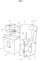
- Figure 1 shows a display base 1 according to the invention with a casing 2.
- the top of a compartment 3 can be seen in the interior of the casing 2.
- the front side wall 6 has a removal opening 7 in the middle from which a product compartment 10 protrudes. Above the removal opening 7 there is a removal flap 17, which is not used here.
- FIG. 2 shows an exploded view of the components of the display base according to the invention from Figure 1 .
- the casing 2 can be seen with an empty interior.
- the two components of the merchandise compartment unit 8 namely the shaft 9 and a merchandise compartment 10
- the merchandise compartment 10 is designed here as a half-closed dispenser with a dispensing opening 22.
- the shaft has three fastening tabs 18 at its front end, with which it is attached to the display casing.
- two web elements 4 and 5 are shown, which form the compartment 3.
- a cutout 11 is arranged in the first web element 4 and a cutout 12 is arranged in the second web element 5.
- the cutouts 11,12 are each located in the tips 13 of the compartment.
- the cutouts 11,12 are designed as perforated flaps 19. In the illustration, the perforated flaps 19 are already folded out of the cutout.
- the cutouts 11 and 12 are located at different heights in the web elements 4 and 5.
- the web elements 4 and 5 each have 2 webs 4a, 4b and 5a, 5b respectively.
- the webs are connected to each other via a fold line 20.
- 2 corresponding slots 21 can be seen. The two web elements are pushed into each other using the slots and then form the compartment 3.
- Figure 3a shows the completed compartment 3 with the goods compartment unit 8 inserted into the compartment.
- the compartment 3 is still positioned above the casing 2.
- the goods compartment 10 is completely inserted into the shaft 9.
- the removal flap 17 is folded back into the casing and in the Figure 3a not recognizable.
- Figure 3b the display base 1 according to the invention can be seen with the compartment 3 now pushed in.
- the goods compartment 10 is locked in the shaft 9 by means of the locking flap 16.
- the removal flap 17 is currently folded into the casing in order to increase access to the dispensing opening 22.
- Figure 3c shows the display base 1 according to the invention in an alternative construction variant.
- the locking tab 16 is opened so that the goods compartment 10 can be moved out of the display base 1.
- the goods compartment 10 protrudes accordingly beyond the circumference of the display base 1, which is formed by the casing 2. This corresponds to the Figure 1 shown position.
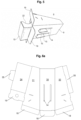
- Figure 4 shows a shaft 9 and the associated goods compartment 10 from below.
- the rail elements 15 are inserted into the guide slots 14 and help the goods compartment 10 to slide in the shaft 9. In addition, the rail elements 15 ensure that the goods compartment 10 does not fall out of the display base.
- Figure 5 shows an assembled goods compartment unit 8 from the underside.
- the goods compartment 10 is arranged in the shaft 9.
- the rail elements 15 are inserted into the two guide slots 14.
- the goods compartment 10 is pulled out to its maximum extension position. It can be seen that the rail elements 15 prevent the goods compartment 10 from being pulled out further.
- Figure 6a shows a one-piece blank for a shaft 9.
- the shaft 9 has a shaft base 30 with two parallel guide slots 14.
- Two shaft side walls 31, 32 are hinged to the right and left of the shaft base 20 via fold lines.
- a shaft top 34 is also hinged to a side wall 31 via a fold line.
- On the front side of the shaft top 34 is the locking flap 16, which forms a surface with the shaft top 34 before folding.
- Fastening tabs 18 are hinged to the front side of the shaft base 30 and the shaft side walls 31, 32.
- the blank has two locking tabs 35, with which the shaft 9 can be closed after unfolding.
- FIG 6b a one-piece blank for a goods compartment 10 is shown.
- the goods compartment 10 has a goods compartment base 40, to which a side wall 41 is hinged.
- the goods compartment top 42 is hinged to the other side of the side wall 41.
- a second side wall 43 is connected to this.
- the two side walls 41 and the goods compartment top 42 have recesses which form the dispensing opening when held open.
- An auxiliary floor 45 is connected to the 2nd side wall 43.
- the goods compartment floor 40 and the auxiliary floor 45 form the underside of the goods compartment 10 when unfolded.
- the goods compartment floor 40 also has 2 rail elements 15.
- the rail elements 15 are not yet unfolded here and lie on the same level as the goods compartment floor 40.
- An upstand 46 is attached to the front side of the goods compartment floor 40. When unfolded, this forms a front edge together with the tabs 47 which prevents goods from falling out of the goods compartment.
- the shaft is closed off at the rear by the shaft rear wall 48.
Landscapes
- Vending Machines For Individual Products (AREA)
- Display Racks (AREA)
Description
- Gegenstand der Erfindung ist ein Displaysockel aufweisend einen Mantel und ein Gefache als Stabilisierungselement, wobei das Gefache im Mantel angeordnet ist und das Gefache aus mindestens einem Stegelement gebildet wird.
- Zur Präsentation von Waren im Handel oder auf Messen werden häufig Displays mit Regalböden verwendet. Diese schaffen eine zusätzliche Verkaufsfläche und ermöglichen es bei Sonderaktionen Ware gezielt zur präsentieren. Die Displays sind entweder regalartig aufgebaut oder bestehen aus einem Oberbau z.B. mit Warenfächern und einem Displaysockel. Bisher werden Displaysockel als stabiles Unterteil und ggf. zusätzlich als Kommunikationsfläche genutzt und auf ihnen werden die Produkte oder Werbeschilder platziert. Der Raum im Sockel ist leer und wird nur ggf. für ein Gefache zur Stabilisierung des Sockels benutzt.
- Ein handelsüblicher Displaysockel ist aus der
DE 91 08 821U1 bekannt. Der Displaysockel weist einen zusammenfaltbaren Mantel mit einem separaten Innenteil zur Stabilisierung auf. Auf der Oberseite schließt der Sockel mit einer Palette ab. Der Raum im Sockel ist bis auf die diagonalen Stabilisierungselemente leer. - Aus der
DE 10 2014 215 122 A1 ist ein weiterer Displaysockel bekannt, der einen Mantel und ein Innengefache hat. Durch die besondere Konstruktion des Innengefaches wird eine hohe Stabilität erreicht. Der Sockel lässt sich zudem leicht aufstellen und kostengünstig herstellen. - Aus der
US2013/0313311 A1 ist ein Ausgabebehälter bekannt, der auch als Displaysockel aufgefasst werden kann. Der Ausgabebehälter weist ein Warenfach auf, wobei Waren im Warenfach aus einer Entnahmeöffnung in der Außenwand des Ausgabebehälters zu entnehmen sind. - Aufgabe der Erfindung ist es einen stabilen Displaysockel bereit zu stellen, der eine vielseitige Nutzung des Sockels erlaubt.
- Die Aufgabe wird erfindungsgemäß gelöst durch einen Displaysockel gemäß Patentanspruch 1.
- Weitergehende Ausführungsformen sind Gegenstand der Unteransprüche oder nachfolgend beschrieben.
- Der erfindungsgemäße Displaysockel weist einen Mantel und ein Gefache als Stabilisierungselement auf, wobei das Gefache im Innenraum des Mantels angeordnet ist. Das Gefache wird aus mindestens einem Stegelement gebildet. Der erfindungsgemäße Displaysockel hat in einer Seitenwand des Mantels eine Entnahmeöffnung. Im Displaysockel ist mindestens eine Warenfacheinheit angeordnet, die einen Schacht und ein Warenfach (Spender) hat, wobei das Warenfach im Schacht angeordnet ist, bevorzugt in den Schacht eingeschoben ist. Der Schacht ist entweder als geschlossener Schacht beispielsweise pyramidenstumpf- oder quaderförmig ausgebildet und hat einen vieleckigen z.B. rechteckigen Querschnitt. Alternativ ist der Schacht als offener Schacht z.B. in Form einer Rinne mit Boden und zwei Seitenwänden ausgebildet. Eine kurze Seite des Schachts ist an der Entnahmeöffnung in der Seitenwand angeordnet. Das Gefache weist weiterhin mindestens zwei Ausstanzungen auf und die Ausstanzung ist jeweils mindestens so groß wie der Querschnitt der Warenfacheinheit, bevorzugt wie der Querschnitt des Schachts. Dadurch ergibt sich im aufgebauten Zustand ein Kanal im Gefache. In diesen Kanal wird die Warenfacheinheit geschoben. Die Warenfacheinheit ist in den Ausstanzungen angeordnet. Die Form und Breite der Ausstanzungen sind variabel.
- Das Warenfach bildet einen zusätzlichen Raum zur Präsentation von Waren. Der erfindungsgemäße Displaysockel dient somit nicht nur als Unterteil eines Displays und ggf. als Kommunikationsfläche, sondern der Leerraum im Sockelinneren wird zum Transport, zur Lagerung und zur Präsentation von Waren genutzt. Die Größe, Anzahl oder Position der Warenfacheinheit ist variabel. Größe und Anzahl können je nach Ware und Anzahl der sich im Display befindenden Ware variiert werden. Auch die Größe und Form des Warenfachs kann an jeden Displaysockel angepasst werden. In einer Ausführung ist das Warenfach als geschlossenen Körper mit einer Ausgabeöffnung gestaltet. Die Ausgabeöffnung an der Vorderseite des Spenders dient zur Produktentnahme. Auch hier ist die Größe und die Form der Ausgabeöffnung variabel. Wichtig ist nur, dass eine Öffnung zur Entnahme der Ware vorhanden ist.
Der Querschnitt des Gefaches entspricht bevorzugt einem X, einem doppelten X oder einem Quadrat. Bevorzugt ist der Querschnitt des Gefaches ein doppeltes X. Das Gefache wird in einer Ausführungsform aus mindestens zwei Stegelementen A und B gebildet wird, die ineinander gesteckt sind. Das Gefache weist bevorzugt genau zwei Stegelemente auf, die jeweils aus zwei Stegen bestehen, wobei die zwei Stege mit einer Falzlinie miteinander verbunden sind. Die Stegelemente weisen bevorzugt Steckschlitze auf und werden mit Hilfe dieser Steckschlitze ineinander geschoben, so dass ein Gefache entsteht, dass bevorzugt den Querschnitt eines doppelten X hat. Die Stegelemente kreuzen sich entsprechend in zwei Punkten. - Das Gefache weist bevorzugt zwei Ausstanzungen auf und die Ausstanzungen sind optional in den Spitzen des Gefachs angeordnet. Die Spitzen werden z.B. durch die Verbindung der beiden X oder die Ecken des Quadrates gebildet. Bei der Ausführungsform mit genau zwei Stegelementen ist die Ausstanzung entsprechend im Bereich der Falzlinie angeordnet, so dass die Falzlinie nicht durchgängig von oben nach unten verläuft.
- Bevorzugt sind die Ausstanzungen in verschiedenen Höhen in dem Stegelement bzw. den Stegelementen angeordnet, d.h. die Ausstanzung in einem Stegelement befindet sich vertikal in einer anderen Position als die zweite Ausstanzung in dem Stegelement oder einem zweiten Stegelement. Die verschiedenen Seiten der Warenfacheinheit, die in den Ausstanzungen positioniert sind, befinden sich hierdurch ebenfalls auf unterschiedlichen Höhen, so dass die Warenfacheinheit angewinkelt im Displaysockel liegt. Die Warenfacheinheit wird dabei so positioniert, dass sich der niedrigste Punkt der Warenfacheinheit bevorzugt an der Entnahmeöffnung befindet. Hierdurch rutscht Ware, die sich im Warenfach befindet, bedingt durch die Schwerkraft immer in Richtung der Entnahmeöffnung. Die angewinkelte Position sorgt dafür, dass die Ware im Warenfach immer wieder nach vorne nachrutscht.
- Die Ausstanzungen sind in einer Ausführungsform als Lochklappenausstanzungen ausgebildet. Dieses hat den Vorteil, dass für das Stegelement ein vollflächige Zustand verwendet werden kann, indem durch Ausstanzungen eine oder mehrere Klappen erzeugt werden. Durch Öffnen der Klappe(n), ähnlich wie bei einem Fensterladen, entsteht dann ein Loch, das heißt eine Öffnung zur Aufnahme der Warenfacheinheit.
- Das Warenfach ist in den Schacht geschoben. Der Schacht weist mindestens einen Führungsschlitz und das Warenfach mindestens ein Schienenelement auf. Das Schienenelement ist in dem Führungsschlitz positioniert. Hierdurch ist es möglich, dass das Warenfach kontrolliert entlang einer vorgegebenen Richtung in Position gebracht wird oder selbsttätig in Position rutscht. Der Führungsschlitz und das Schienenelement sind bevorzugt an der Unterseite des Schachts bzw. des Warenfachs angeordnet.
- In einer Ausführungsform weist der erfindungsgemäße Displaysockel eine Arretierungsklappe für das Warenfach auf, mit der das Warenfach in seiner Position im Schacht und im Displaysockel fixiert wird.
- Der erfindungsgemäße Displaysockel besteht bevorzugt aus Pappe, Karton, Wellpappe, Kunststoff oder einer Mischung hiervon, besonders bevorzugt aus Wellpappe. Das Material kann eingefärbt, bedruckt, kaschiert oder beklebt oder auf andere übliche Weise verziert sein.
- Der erfindungsgemäße Displaysockel ist variabel in seiner Form und Größe. Größe und Form des erfindungsmäßen Displaysockels sind dabei individuell anpassbar. Der erfindungsgemäße Displaysockel hat beispielsweise die Form eines Quaders, eines Zylinders oder eines Prismas. Auch die Warenfacheinheit und insbesondere das Warenfach kann an jedes Produkt angepasst werden.
- Bisher wurden Displaysockel als Kommunikationsfläche genutzt und auf ihnen wurden die Produkte platziert. Der Raum im Sockel stellte bisher bis auf Stabilisierungselemente eine ungenutzte Fläche dar. Mit dem erfindungsgemäßen Displaysockel erfährt der Sockel einen weiteren Nutzen und wird zur Präsentation von Ware und ggf. zum Transport der Ware benutzt, was dem Sockel einen Mehrwert verleiht.
- In einer Ausführungsform wird der erfindungsgemäße Displaysockel mit einer Verpackung z.B. einer Haube für den Versand versehen. Beim Abziehen der Verpackung bzw. der Haube fährt die Warenfacheinheit aus dem Sockel heraus, wenn die Warenfacheinheit angewinkelt im Sockel liegt.
- Aus der Warenfacheinheit des erfindungsgemäßen Displaysockels kann zusätzlich Ware verkauft werden. Die Warenfacheinheit muss nicht im Handel angebracht werden oder befüllt werden. Die Ware liegt bevorzugt bereits beim Versand im Sockel.
- In einer Ausführungsform hat das Gefache Ausstanzungen bevorzugt in verschiedenen Höhen. In dieses Gefache wird der Schacht geschoben, in dem das Warenfach bevorzugt mit Schienenelementen arretiert ist. Die verschiedenen Höhen im Gefache sorgen dann dafür, dass der Schacht mit dem Warenfach angewinkelt steht. Wenn das Warenfach nicht arretiert ist, gleitet die Warenfacheinheit im Schacht ganz von allein aus dem Displaysockel. Bei einer Schrägstellung und entsprechendem Eigengewicht der Ware, kann diese im Warenfach von allein immer wieder nach vorne rutschen, was den Verkauf der Ware erleichtert.
- In einer Ausführungsform weist die Warenfacheinheit einer Schienentechnik auf. Der Schacht weist hierfür mindestens einen Führungsschlitz auf, bevorzugt an der Schachtunterseite, besonders bevorzugt zwei parallele Führungsschlitze. Das Warenfach weist mindestens ein korrespondierendes Schienenelement auf, das in den Führungsschlitz gesteckt wird. Bevorzugt weist das Warenfach mindestens ein Schienenelement an der Unterseite auf. Der Schacht und das Warenfach weisen jeweils miteinander korrespondierende Führungsschlitze und Schienenelemente auf. Durch die Ausführungsform mit Schienentechnik mit mindestens einem Führungsschlitz im Schacht und mindestens einem Schienenelement am Warenfach wird eine besonders gute Führung des Warenfachs erreicht.
- Zusätzlich gibt es die Möglichkeit das Warenfach auch im erfindungsgemäßen Displaysockel zu Arretieren, falls dieses nicht aus dem Displaysockel ragen, sondern z.B. bündig mit der Seitenwand abschließen soll. Der erfindungsgemäße Displaysockel weist in dieser Ausführungsform eine Arretierungsklappe für das Warenfach auf. Die Arretierungsklappe ist bevorzugt am Schacht befestigt. Die Arretierungsklappe wird in den Schacht runtergedrückt und sorgt dafür, dass das Warenfach nicht ausfährt, da sie das Warenfach in seiner Position arretiert. Um trotzdem die Ware gut erreichen zu können, wird bevorzugt eine Entnahmeklappe am Displaysockel eingeklappt, was eine einfache Entnahme ermöglicht. Die Entnahmeklappe ist bevorzugt Teil der Seitenwand mit der Entnahmeöffnung und besonders bevorzugt über der Entnahmeöffnung angeordnet.
- Der erfindungsgemäße Displaysockel besteht aus einem mehrteiligen Zuschnitt. Der erfindungsgemäße Displaysockel wird aufgestellt, indem die Stegelemente des Gefaches ineinander geschoben werden. Anschließend kann die Warenfacheinheit, verbunden mit dem Schacht in das Gefache geschoben werden. Das Gefache mit eingeschobener Warenfacheinheit wird in dem Mantel geschoben. Durch den Mantel bleibt das Gefache in Form. Der Mantel dient als Rahmen. Der Schacht steckt komplett in den Ausstanzungen. Dieses sorgt dafür, dass das Gefache auch mit Lochausstanzungen genug Tragfähigkeit hat.
- Die Erfindung wird anhand der Figuren näher erläutert. Es zeigen
- Fig. 1
- einen erfindungsgemäßen Displaysockel,
- Fig. 2
- eine Explosionszeichnung eines Displaysockels gemäß
Figur 1 , - Fig. 3a
- einen erfindungsgemäßen Sockel mit Gefache vor dem Einschieben,
- Fig. 3b
- den Displaysockel gemäß
Figur 3a mit eingeschobenem Gefache, - Fig. 4
- einen Schacht und ein Warenfach nebeneinander,
- Fig. 5
- eine Warenfacheinheit von unten und
- Figur 6
- einen Zuschnitt für eine Warenfacheinheit.
-
Figur 1 zeigt einen erfindungsgemäßen Displaysockel 1 mit einem Mantel 2. Im Innenraum des Mantels 2 ist die Oberseite eines Gefache 3 erkennbar. Die vordere Seitenwand 6 hat mittig eine Entnahmeöffnung 7 aus der ein Warenfach 10 herausragt. Oberhalb der Entnahmeöffnung 7 ist eine Entnahmeklappe 17 angeordnet, die hier nicht genutzt wird. -
Figur 2 zeigt eine Explosionsdarstellung der Bauteile des erfindungsgemäßen Displaysockels ausFigur 1 . Unten links ist der Mantel 2 mit leerem Innenraum zu sehen. In der oberen linken Ecke sind die beiden Bauteile der Warenfacheinheit 8, nämlich der Schacht 9 und ein Warenfach 10 zu erkennen. Das Warenfach 10 ist hier als halbgeschlossener Spender mit einer Ausgabeöffnung 22 ausgeführt. Der Schacht hat an seinem vorderen Ende drei Befestigungslaschen 18, mit denen er am Displaymantel befestigt wird. Auf der rechten Seite sind zwei Stegelement 4 und 5 dargestellt, die das Gefache 3 bilden. Im ersten Stegelement 4 ist eine Ausstanzung 11 angeordnet und im zweiten Stegelement 5 ist eine Ausstanzung 12 angeordnet. Die Ausstanzungen 11,12 befinden sich dabei jeweils in den Spitzen 13 des Gefaches. Die Ausstanzungen 11,12 sind als Lochklappen 19 ausgestaltet. In der Darstellung sind die Lochklappen 19 bereits aus der Ausstanzung heraus gefaltet. Die Ausstanzungen 11 und 12 befinden sich auf verschiedenen Höhen in den Stegelementen 4 und 5. Die Stegelementen 4 und 5 weisen jeweils 2 Stege 4a, 4b bzw. 5a, 5b auf. Die Stege sind über eine Faltlinie 20 miteinander verbunden. An der Unterseite des Stegelements 14 sind zwei Steckschlitze 21 zu erkennen, die jeweils in einem Steg angeordnet sind. An der Oberseite des Stegelements 15 sind 2 korrespondierende Steckschlitze 21 zu erkennen. Die beiden Stegelemente werden mithilfe der Steckschlitze ineinandergeschoben und bilden dann das Gefache 3. -
Figur 3a zeigt das fertig gesteckte Gefache 3 mit ins Gefache eingeschobener Warenfacheinheit 8. Das Gefache 3 ist noch oberhalb des Mantels 2 positioniert. Das Warenfach 10 ist vollständig in den Schacht 9 eingeschoben. Die Entnahmeklappe 17 ist nach hinten in den Mantel gefaltet und in derFigur 3a nicht erkennbar. InFigur 3b ist der erfindungsgemäße Displaysockel 1 mit nun eingeschobenem Gefache 3 erkennbar. Das Warenfach 10 ist mit Hilfe der Arretierungsklappe 16 im Schacht 9 arretiert. Derzeitig ist die Entnahmeklappe 17 in den Mantel geklappt, um den Zugriff auf die Ausgabeöffnung 22 zu vergrößern.Figur 3c zeigt den erfindungsgemäßen Displaysockel 1 in einer alternativen Aufbauvariante. Die Arretierungslasche 16 ist geöffnet, so dass das Warenfach 10 aus dem Displaysockel 1 herausfahren kann. Das Warenfach 10 ragt entsprechend über den Umfang des Displaysockels 1, der durch den Mantel 2 gebildet wird, heraus. Dieses entspricht der inFigur 1 gezeigten Position. -
Figur 4 zeigt einen Schacht 9 und das zugehörige Warenfach 10 von unten. An der Unterseite des Schachtes 9 sind zwei Führungsschlitze 14 angeordnet, die parallel zueinander verlaufen. An der Unterseite des Warenfach 10 sind zwei L-förmige Schienenelemente 15 angeordnet. Die Schienenelemente 15 werden in die Führungsschlitze 14 gesteckt und helfen dem Warenfach 10 im Schacht 9 zu gleiten. Außerdem sorgen die Schienenelement 15 dafür, dass das Warenfach 10 nicht aus dem Displaysockel fällt. -
Figur 5 zeigt eine montierte Warenfacheinheit 8 von der Unterseite. Das Warenfach 10 ist im Schacht 9 angeordnet. Die Schienenelemente 15 sind in den beiden Führungsschlitzen 14 eingesteckt. Das Warenfach 10 ist in seine maximale Auszugsposition ausgezogen. Es ist erkennbar, dass die Schienenelemente 15 verhindern, dass das Warenfach 10 weiter herausgezogen wird. -
Figur 6a zeigt einen einteiligen Zuschnitt für einen Schacht 9. Der Schacht 9 weist einen Schachtboden 30 mit zwei parallelen Führungsschlitzen 14 auf. Rechts und links an den Schachtboden 20 sind über Faltlinien zwei Schachtseitenwände 31, 32 angelenkt. An eine Seitenwand 31 ist zudem über eine Faltlinie eine Schachtoberseite 34 angelenkt. An der vorderen Seite der Schachtoberseite 34 befindet sich die Arretierungsklappe 16, die vor dem Einklappen eine Fläche mit der Schachtoberseite 34 bildet. An der vorderen Seite des Schachtboden 30 und der Schachtseitenwände 31,32 sind jeweils Befestigungslaschen 18 angelenkt. Der Zuschnitt weist zwei Verschlusslaschen 35 auf, mit denen der Schacht 9 nach dem Auffalten verschlossen werden kann. - In
Figur 6b ist ein einteiliger Zuschnitt für ein Warenfach 10 dargestellt. Das Warenfach 10 hat einen Warenfachboden 40, an denen eine Seitenwand 41 angelenkt ist. Auf die andere Seite der Seitenwand 41 ist die Warenfachoberseite 42 angelenkt. An diese schließt sich eine 2. Seitenwand 43 an. Die beiden Seitenwände 41 und die Warenfachoberseite 42 weisen Ausnehmungen auf, die nach dem aufhalten die Ausgabeöffnung bilden. In der Warenfachoberseite 42 befindet sich ein Einsteckschlitz 44, in dem die Arretierungslasche positioniert werden kann. An die 2. Seitenwand und 43 schließt sich ein Hilfsboden 45 an. Der Warenfachboden 40 und der Hilfsboden 45 bilden im aufgefalteten Zustand die Unterseite des Warenfachs 10. Der Warenfach Boden 40 weist zudem 2 Schienenelemente 15 auf. Die Schienenelement 15 sind hier noch nicht aufgefaltet und liegen in einer Ebene mit dem Warenfach Boden 40. An der vorderen Seite des Warenfachbodens 40 ist eine Aufkantung 46 angebracht. Diese bildet im aufgefalteten Zustand zusammen mit den Laschen 47 einen vorderen Rand, der verhindert das Ware aus dem Warenfach herausfällt. Zur Rückseite wird der Schacht durch die Schachtrückwand 48 abgeschlossen. -
Displaysockel 1 Mantel 2 Gefache 3 Stegelement 4 Stegelement 5 Seitenwand 6 Entnahmeöffnung 7 Warenfacheinheit 8 Schacht 9 Warenfach(Spender) 10 Ausstanzung 11 Ausstanzung 12 Spitze des Gefaches 13 Führungsschlitz 14 Schienenelement 15 Arretierungsklappe 16 Entnahmeklappe 17 Befestigungslasche 18 Lochklappe 19 Faltlinie 20 Steckschlitz 21 Ausgabeöffnung 22 Schachtboden 30 Schachtseitenwand 31 Schachtseitenwand 32 Schachtoberseite 34 Verschlusslaschen 35 Warenfachboden 40 Schachtseitenwand 41 Warenfachoberseite 42 Schachtseitenwand 43 Einsteckschlitz 44 Hilfsboden 45 Aufkantung 46 Laschen 47 Schachtrückwand 48
Claims (9)
- Displaysockel (1) aufweisend einen Mantel (2) und ein Gefache (3) als Stabilisierungselement, wobei das Gefache (3) im Innenraum des Mantels (2) angeordnet ist und das Gefache (3) aus mindestens einem Stegelement gebildet wird, wobei• der Displaysockel (1) in einer Seitenwand (6) eine Entnahmeöffnung (7) aufweist,• im Displaysockel (1) mindestens eine Warenfacheinheit (8) mit einem Schacht (9) und einem Warenfach (10) angeordnet ist, wobei das Warenfach (10) im Schacht (9) angeordnet ist und eine kurze Seite des Schachtes (9) an der Entnahmeöffnung (7) angeordnet ist,
dadurch gekennzeichnet, dass• das Gefache (3) mindestens zwei Ausstanzungen (11, 12) hat und die Ausstanzung (11, 12) jeweils mindestens so groß wie der Querschnitt der Warenfacheinheit ist,• die Warenfacheinheit (8) in den Ausstanzungen (11, 12) angeordnet ist,• das Warenfach (10) in den Schacht (9) geschoben ist und• der Schacht (9) mindestens einen Führungsschlitz (14) und das Warenfach (8) mindestens ein Schienenelement (15) aufweist und das Schienenelement (15) in dem Führungsschlitz (14) positioniert ist. - Displaysockel gemäß Patentanspruch 1, dadurch gekennzeichnet, dass das Gefache (3) aus mindestens zwei Stegelementen A und B (4,5) gebildet wird, die ineinander gesteckt sind.
- Displaysockel (1) gemäß Patentanspruch 1 oder 2, dadurch gekennzeichnet, dass das Gefache genau zwei Stegelemente (4,5) aufweist, die jeweils aus zwei Stegen (4a, 4b) (5a, 5b) bestehen, wobei die zwei Stege mit einer Falzlinie (F) miteinander verbunden sind.
- Displaysockel (1) gemäß einem der vorhergehenden Patentansprüche, dadurch gekennzeichnet, dass der Querschnitt des Gefaches (3) ein X, ein doppeltes X oder ein Quadrat ist, bevorzugt ein doppeltes X.
- Displaysockel (1) gemäß einem der vorhergehenden Patentansprüche, dadurch gekennzeichnet, dass die Ausstanzungen (11,12) als Lochklappenausstanzungen ausgebildet sind.
- Displaysockel (1) gemäß einem der vorhergehenden Patentansprüche, dadurch gekennzeichnet, dass das Gefache (3) zwei Ausstanzungen aufweist und die Ausstanzungen (11, 12) in den Spitzen (13) des Gefaches (3) angeordnet sind.
- Displaysockel (1) gemäß einem der vorhergehenden Patentansprüche, dadurch gekennzeichnet, dass die Ausstanzungen (11, 12) in verschiedenen Höhen angeordnet sind, so dass die Warenfacheinheit (8) angewinkelt im Displaysockel (1) liegt, wobei sich der niedrigste Punkt der Warenfacheinheit (8) bevorzugt an der Entnahmeöffnung (7) befindet.
- Displaysockel (1) gemäß einem der vorhergehenden Patentansprüche, dadurch gekennzeichnet, dass der Displaysockel (1) eine Arretierungsklappe (16) für das Warenfach (10) aufweist.
- Displaysockel (1) gemäß einem der vorhergehenden Patentansprüche, dadurch gekennzeichnet, dass der Displaysockel aus Pappe, Karton, Wellpappe, Kunststoff oder einer Mischung hiervon, bevorzugt aus Wellpappe besteht.
Priority Applications (1)
| Application Number | Priority Date | Filing Date | Title |
|---|---|---|---|
| PL17203462T PL3354167T3 (pl) | 2017-01-27 | 2017-11-24 | Słupek ekspozycyjny z półką na towary w słupku |
Applications Claiming Priority (1)
| Application Number | Priority Date | Filing Date | Title |
|---|---|---|---|
| DE102017101643.0A DE102017101643B4 (de) | 2017-01-27 | 2017-01-27 | Displaysockel mit Warenfach im Sockel |
Publications (3)
| Publication Number | Publication Date |
|---|---|
| EP3354167A1 EP3354167A1 (de) | 2018-08-01 |
| EP3354167B1 EP3354167B1 (de) | 2019-03-06 |
| EP3354167B2 true EP3354167B2 (de) | 2025-01-01 |
Family
ID=60480176
Family Applications (1)
| Application Number | Title | Priority Date | Filing Date |
|---|---|---|---|
| EP17203462.1A Active EP3354167B2 (de) | 2017-01-27 | 2017-11-24 | Displaysockel mit warenfach im sockel |
Country Status (3)
| Country | Link |
|---|---|
| EP (1) | EP3354167B2 (de) |
| DE (1) | DE102017101643B4 (de) |
| PL (1) | PL3354167T3 (de) |
Families Citing this family (1)
| Publication number | Priority date | Publication date | Assignee | Title |
|---|---|---|---|---|
| CN110367762A (zh) * | 2019-08-23 | 2019-10-25 | 南京云设智能科技有限公司 | 一种物联智能资料宣传架 |
Family Cites Families (13)
| Publication number | Priority date | Publication date | Assignee | Title |
|---|---|---|---|---|
| DE8220254U1 (de) | 1982-07-15 | 1982-10-14 | Philip Morris GmbH, 8000 München | Behaelter zur praesentation von gegenstaenden |
| DE8704047U1 (de) | 1987-03-18 | 1987-04-30 | Herzberger Papierfabrik Ludwig Osthushenrich Gmbh & Co Kg, 3420 Herzberg | Transportverpackung aus Pappe |
| DE3905776A1 (de) | 1989-02-24 | 1990-09-06 | Walter W Dipl Ing Graffunder | Faltbehaelter mit integriertem diagonalgefache |
| DE9108821U1 (de) | 1991-07-18 | 1991-09-19 | Weiss, Bernd, 7500 Karlsruhe | Displaysockel, insbesondere tragend |
| DE9115812U1 (de) | 1991-12-20 | 1992-02-20 | Heinrich Götz & Sohn GmbH, 6955 Aglasterhausen | Regal mit mehreren Regalständern |
| US6695167B2 (en) | 2001-03-23 | 2004-02-24 | Nestec S.A. | Container for holding and dispensing product |
| DE20308698U1 (de) | 2003-06-04 | 2003-09-18 | Heuchemer Verpackung GmbH & Co. KG, 56357 Miehlen | Ausgabebehälter |
| DE10325233A1 (de) * | 2003-06-04 | 2004-12-23 | Heuchemer Verpackung Gmbh & Co. Kg | Ausgabebehälter |
| DE102009014838B4 (de) | 2009-03-27 | 2020-08-13 | Thimm Verpackung Gmbh + Co. Kg | Transport- und Verkaufsverpackung sowie Verfahren zur Verpackung von Produkten |
| US9120612B2 (en) * | 2012-05-24 | 2015-09-01 | Altria Client Services Inc. | Folded dispensing unit and blank |
| DE202014102165U1 (de) | 2014-05-09 | 2014-06-16 | Packwell Gmbh & Co. Kg | Faltkörper mit integrierter Stützkonstruktion aus vorzugsweise Well- oder Vollpappe |
| DE102014215122A1 (de) | 2014-07-31 | 2016-02-04 | Sti Gustav Stabernack Gmbh | Transportabler Sockel |
| DE202015102755U1 (de) | 2015-05-28 | 2015-07-06 | Red-U Gmbh | Vorrichtung zur Lagerung und Präsentation von Waren |
-
2017
- 2017-01-27 DE DE102017101643.0A patent/DE102017101643B4/de active Active
- 2017-11-24 EP EP17203462.1A patent/EP3354167B2/de active Active
- 2017-11-24 PL PL17203462T patent/PL3354167T3/pl unknown
Also Published As
| Publication number | Publication date |
|---|---|
| DE102017101643B4 (de) | 2019-04-04 |
| EP3354167A1 (de) | 2018-08-01 |
| PL3354167T3 (pl) | 2019-08-30 |
| EP3354167B1 (de) | 2019-03-06 |
| DE102017101643A1 (de) | 2018-08-02 |
Similar Documents
| Publication | Publication Date | Title |
|---|---|---|
| DE3101975A1 (de) | Verpackung fuer eine vielzahl von ausstellungspackungen | |
| DE1586869B1 (de) | Einstueckig geformter Karton zur Aufnahme empfindlicher Gegenstaende,insbesondere Eier | |
| EP2883480B1 (de) | Variables Regaldisplay | |
| EP3354167B2 (de) | Displaysockel mit warenfach im sockel | |
| EP2604146B1 (de) | Regal | |
| EP1961344A1 (de) | Auszuglasche | |
| DE60314612T2 (de) | Behälter | |
| EP0423754B1 (de) | Versand- und Verkaufsbehälter | |
| CH537321A (de) | Verpackung, insbesondere für Kekse | |
| DE102016105236B4 (de) | Faltkarton mit einem Gefache | |
| DE60012841T2 (de) | Verpackung zum Verpacken und Darstellen von Artikelgruppen | |
| DE4140030C1 (en) | Foldable box with six walls and partitions - has one side wall coupled to single compartment bottom via fold line | |
| EP3628606A1 (de) | Displaysystem mit zumindest zwei trays | |
| DE4204075C2 (de) | Transportverpackung | |
| DE3441383C2 (de) | ||
| DE1511144A1 (de) | Schau- und Versandpackung,insbesondere fuer Flaschen | |
| DE202018005977U1 (de) | Selbst aufbaubare, stapelbare Kiste | |
| AT521145B1 (de) | Zuschnitt für einen Verpackungskarton | |
| DE202017100152U1 (de) | Einteiliger Zuschnitt für Stufendisplay und einteiliges Stufendisplay | |
| DE29509114U1 (de) | Doppelkammer-Ampullenverpackung | |
| DE9210112U1 (de) | Behältersystem | |
| AT17484U1 (de) | Präsentationssystem mit Regal | |
| DE202011003945U1 (de) | Boden-Display zum Präsentieren von Flaschen und gleichzeitig Transportverpackung | |
| DE10356825A1 (de) | Stapelbarer Transportbehälter aus Wellpappe und Zuschnitt dafür | |
| DE29707921U1 (de) | Verpackungsvorrichtung für Waren |
Legal Events
| Date | Code | Title | Description |
|---|---|---|---|
| PUAI | Public reference made under article 153(3) epc to a published international application that has entered the european phase |
Free format text: ORIGINAL CODE: 0009012 |
|
| STAA | Information on the status of an ep patent application or granted ep patent |
Free format text: STATUS: REQUEST FOR EXAMINATION WAS MADE |
|
| 17P | Request for examination filed |
Effective date: 20180607 |
|
| AK | Designated contracting states |
Kind code of ref document: A1 Designated state(s): AL AT BE BG CH CY CZ DE DK EE ES FI FR GB GR HR HU IE IS IT LI LT LU LV MC MK MT NL NO PL PT RO RS SE SI SK SM TR |
|
| AX | Request for extension of the european patent |
Extension state: BA ME |
|
| GRAP | Despatch of communication of intention to grant a patent |
Free format text: ORIGINAL CODE: EPIDOSNIGR1 |
|
| STAA | Information on the status of an ep patent application or granted ep patent |
Free format text: STATUS: GRANT OF PATENT IS INTENDED |
|
| INTG | Intention to grant announced |
Effective date: 20181212 |
|
| GRAS | Grant fee paid |
Free format text: ORIGINAL CODE: EPIDOSNIGR3 |
|
| GRAA | (expected) grant |
Free format text: ORIGINAL CODE: 0009210 |
|
| STAA | Information on the status of an ep patent application or granted ep patent |
Free format text: STATUS: THE PATENT HAS BEEN GRANTED |
|
| AK | Designated contracting states |
Kind code of ref document: B1 Designated state(s): AL AT BE BG CH CY CZ DE DK EE ES FI FR GB GR HR HU IE IS IT LI LT LU LV MC MK MT NL NO PL PT RO RS SE SI SK SM TR |
|
| REG | Reference to a national code |
Ref country code: GB Ref legal event code: FG4D Free format text: NOT ENGLISH |
|
| REG | Reference to a national code |
Ref country code: CH Ref legal event code: EP Ref country code: AT Ref legal event code: REF Ref document number: 1103418 Country of ref document: AT Kind code of ref document: T Effective date: 20190315 |
|
| REG | Reference to a national code |
Ref country code: DE Ref legal event code: R096 Ref document number: 502017000887 Country of ref document: DE |
|
| REG | Reference to a national code |
Ref country code: IE Ref legal event code: FG4D Free format text: LANGUAGE OF EP DOCUMENT: GERMAN |
|
| REG | Reference to a national code |
Ref country code: CH Ref legal event code: NV Representative=s name: FREI PATENTANWALTSBUERO AG, CH |
|
| REG | Reference to a national code |
Ref country code: NL Ref legal event code: MP Effective date: 20190306 |
|
| REG | Reference to a national code |
Ref country code: LT Ref legal event code: MG4D |
|
| PG25 | Lapsed in a contracting state [announced via postgrant information from national office to epo] |
Ref country code: SE Free format text: LAPSE BECAUSE OF FAILURE TO SUBMIT A TRANSLATION OF THE DESCRIPTION OR TO PAY THE FEE WITHIN THE PRESCRIBED TIME-LIMIT Effective date: 20190306 Ref country code: NO Free format text: LAPSE BECAUSE OF FAILURE TO SUBMIT A TRANSLATION OF THE DESCRIPTION OR TO PAY THE FEE WITHIN THE PRESCRIBED TIME-LIMIT Effective date: 20190606 Ref country code: LT Free format text: LAPSE BECAUSE OF FAILURE TO SUBMIT A TRANSLATION OF THE DESCRIPTION OR TO PAY THE FEE WITHIN THE PRESCRIBED TIME-LIMIT Effective date: 20190306 Ref country code: FI Free format text: LAPSE BECAUSE OF FAILURE TO SUBMIT A TRANSLATION OF THE DESCRIPTION OR TO PAY THE FEE WITHIN THE PRESCRIBED TIME-LIMIT Effective date: 20190306 |
|
| PG25 | Lapsed in a contracting state [announced via postgrant information from national office to epo] |
Ref country code: NL Free format text: LAPSE BECAUSE OF FAILURE TO SUBMIT A TRANSLATION OF THE DESCRIPTION OR TO PAY THE FEE WITHIN THE PRESCRIBED TIME-LIMIT Effective date: 20190306 Ref country code: GR Free format text: LAPSE BECAUSE OF FAILURE TO SUBMIT A TRANSLATION OF THE DESCRIPTION OR TO PAY THE FEE WITHIN THE PRESCRIBED TIME-LIMIT Effective date: 20190607 Ref country code: HR Free format text: LAPSE BECAUSE OF FAILURE TO SUBMIT A TRANSLATION OF THE DESCRIPTION OR TO PAY THE FEE WITHIN THE PRESCRIBED TIME-LIMIT Effective date: 20190306 Ref country code: BG Free format text: LAPSE BECAUSE OF FAILURE TO SUBMIT A TRANSLATION OF THE DESCRIPTION OR TO PAY THE FEE WITHIN THE PRESCRIBED TIME-LIMIT Effective date: 20190606 Ref country code: RS Free format text: LAPSE BECAUSE OF FAILURE TO SUBMIT A TRANSLATION OF THE DESCRIPTION OR TO PAY THE FEE WITHIN THE PRESCRIBED TIME-LIMIT Effective date: 20190306 Ref country code: LV Free format text: LAPSE BECAUSE OF FAILURE TO SUBMIT A TRANSLATION OF THE DESCRIPTION OR TO PAY THE FEE WITHIN THE PRESCRIBED TIME-LIMIT Effective date: 20190306 |
|
| PG25 | Lapsed in a contracting state [announced via postgrant information from national office to epo] |
Ref country code: EE Free format text: LAPSE BECAUSE OF FAILURE TO SUBMIT A TRANSLATION OF THE DESCRIPTION OR TO PAY THE FEE WITHIN THE PRESCRIBED TIME-LIMIT Effective date: 20190306 Ref country code: PT Free format text: LAPSE BECAUSE OF FAILURE TO SUBMIT A TRANSLATION OF THE DESCRIPTION OR TO PAY THE FEE WITHIN THE PRESCRIBED TIME-LIMIT Effective date: 20190706 Ref country code: AL Free format text: LAPSE BECAUSE OF FAILURE TO SUBMIT A TRANSLATION OF THE DESCRIPTION OR TO PAY THE FEE WITHIN THE PRESCRIBED TIME-LIMIT Effective date: 20190306 Ref country code: SK Free format text: LAPSE BECAUSE OF FAILURE TO SUBMIT A TRANSLATION OF THE DESCRIPTION OR TO PAY THE FEE WITHIN THE PRESCRIBED TIME-LIMIT Effective date: 20190306 Ref country code: CZ Free format text: LAPSE BECAUSE OF FAILURE TO SUBMIT A TRANSLATION OF THE DESCRIPTION OR TO PAY THE FEE WITHIN THE PRESCRIBED TIME-LIMIT Effective date: 20190306 Ref country code: IT Free format text: LAPSE BECAUSE OF FAILURE TO SUBMIT A TRANSLATION OF THE DESCRIPTION OR TO PAY THE FEE WITHIN THE PRESCRIBED TIME-LIMIT Effective date: 20190306 Ref country code: ES Free format text: LAPSE BECAUSE OF FAILURE TO SUBMIT A TRANSLATION OF THE DESCRIPTION OR TO PAY THE FEE WITHIN THE PRESCRIBED TIME-LIMIT Effective date: 20190306 Ref country code: RO Free format text: LAPSE BECAUSE OF FAILURE TO SUBMIT A TRANSLATION OF THE DESCRIPTION OR TO PAY THE FEE WITHIN THE PRESCRIBED TIME-LIMIT Effective date: 20190306 |
|
| PG25 | Lapsed in a contracting state [announced via postgrant information from national office to epo] |
Ref country code: SM Free format text: LAPSE BECAUSE OF FAILURE TO SUBMIT A TRANSLATION OF THE DESCRIPTION OR TO PAY THE FEE WITHIN THE PRESCRIBED TIME-LIMIT Effective date: 20190306 |
|
| REG | Reference to a national code |
Ref country code: DE Ref legal event code: R026 Ref document number: 502017000887 Country of ref document: DE |
|
| PLBI | Opposition filed |
Free format text: ORIGINAL CODE: 0009260 |
|
| PG25 | Lapsed in a contracting state [announced via postgrant information from national office to epo] |
Ref country code: IS Free format text: LAPSE BECAUSE OF FAILURE TO SUBMIT A TRANSLATION OF THE DESCRIPTION OR TO PAY THE FEE WITHIN THE PRESCRIBED TIME-LIMIT Effective date: 20190706 |
|
| PLAX | Notice of opposition and request to file observation + time limit sent |
Free format text: ORIGINAL CODE: EPIDOSNOBS2 |
|
| 26 | Opposition filed |
Opponent name: ARBEITSKREIS DISPLAY E.V. Effective date: 20191206 |
|
| PG25 | Lapsed in a contracting state [announced via postgrant information from national office to epo] |
Ref country code: DK Free format text: LAPSE BECAUSE OF FAILURE TO SUBMIT A TRANSLATION OF THE DESCRIPTION OR TO PAY THE FEE WITHIN THE PRESCRIBED TIME-LIMIT Effective date: 20190306 |
|
| PGFP | Annual fee paid to national office [announced via postgrant information from national office to epo] |
Ref country code: PL Payment date: 20191113 Year of fee payment: 3 |
|
| PLBB | Reply of patent proprietor to notice(s) of opposition received |
Free format text: ORIGINAL CODE: EPIDOSNOBS3 |
|
| PG25 | Lapsed in a contracting state [announced via postgrant information from national office to epo] |
Ref country code: TR Free format text: LAPSE BECAUSE OF FAILURE TO SUBMIT A TRANSLATION OF THE DESCRIPTION OR TO PAY THE FEE WITHIN THE PRESCRIBED TIME-LIMIT Effective date: 20190306 |
|
| REG | Reference to a national code |
Ref country code: DE Ref legal event code: R082 Ref document number: 502017000887 Country of ref document: DE Representative=s name: PATENTANWAELTE OLBRICHT, BUCHHOLD, KEULERTZ PA, DE |
|
| PG25 | Lapsed in a contracting state [announced via postgrant information from national office to epo] |
Ref country code: LU Free format text: LAPSE BECAUSE OF NON-PAYMENT OF DUE FEES Effective date: 20191124 Ref country code: MC Free format text: LAPSE BECAUSE OF FAILURE TO SUBMIT A TRANSLATION OF THE DESCRIPTION OR TO PAY THE FEE WITHIN THE PRESCRIBED TIME-LIMIT Effective date: 20190306 |
|
| REG | Reference to a national code |
Ref country code: BE Ref legal event code: MM Effective date: 20191130 |
|
| PG25 | Lapsed in a contracting state [announced via postgrant information from national office to epo] |
Ref country code: IE Free format text: LAPSE BECAUSE OF NON-PAYMENT OF DUE FEES Effective date: 20191124 Ref country code: FR Free format text: LAPSE BECAUSE OF NON-PAYMENT OF DUE FEES Effective date: 20191130 |
|
| PG25 | Lapsed in a contracting state [announced via postgrant information from national office to epo] |
Ref country code: BE Free format text: LAPSE BECAUSE OF NON-PAYMENT OF DUE FEES Effective date: 20191130 |
|
| PG25 | Lapsed in a contracting state [announced via postgrant information from national office to epo] |
Ref country code: CY Free format text: LAPSE BECAUSE OF FAILURE TO SUBMIT A TRANSLATION OF THE DESCRIPTION OR TO PAY THE FEE WITHIN THE PRESCRIBED TIME-LIMIT Effective date: 20190306 |
|
| REG | Reference to a national code |
Ref country code: CH Ref legal event code: PL |
|
| PG25 | Lapsed in a contracting state [announced via postgrant information from national office to epo] |
Ref country code: HU Free format text: LAPSE BECAUSE OF FAILURE TO SUBMIT A TRANSLATION OF THE DESCRIPTION OR TO PAY THE FEE WITHIN THE PRESCRIBED TIME-LIMIT; INVALID AB INITIO Effective date: 20171124 Ref country code: MT Free format text: LAPSE BECAUSE OF FAILURE TO SUBMIT A TRANSLATION OF THE DESCRIPTION OR TO PAY THE FEE WITHIN THE PRESCRIBED TIME-LIMIT Effective date: 20190306 |
|
| PG25 | Lapsed in a contracting state [announced via postgrant information from national office to epo] |
Ref country code: CH Free format text: LAPSE BECAUSE OF NON-PAYMENT OF DUE FEES Effective date: 20201130 Ref country code: LI Free format text: LAPSE BECAUSE OF NON-PAYMENT OF DUE FEES Effective date: 20201130 |
|
| APBM | Appeal reference recorded |
Free format text: ORIGINAL CODE: EPIDOSNREFNO |
|
| APBP | Date of receipt of notice of appeal recorded |
Free format text: ORIGINAL CODE: EPIDOSNNOA2O |
|
| APAH | Appeal reference modified |
Free format text: ORIGINAL CODE: EPIDOSCREFNO |
|
| PG25 | Lapsed in a contracting state [announced via postgrant information from national office to epo] |
Ref country code: SI Free format text: LAPSE BECAUSE OF FAILURE TO SUBMIT A TRANSLATION OF THE DESCRIPTION OR TO PAY THE FEE WITHIN THE PRESCRIBED TIME-LIMIT Effective date: 20190306 |
|
| APBQ | Date of receipt of statement of grounds of appeal recorded |
Free format text: ORIGINAL CODE: EPIDOSNNOA3O |
|
| PG25 | Lapsed in a contracting state [announced via postgrant information from national office to epo] |
Ref country code: MK Free format text: LAPSE BECAUSE OF FAILURE TO SUBMIT A TRANSLATION OF THE DESCRIPTION OR TO PAY THE FEE WITHIN THE PRESCRIBED TIME-LIMIT Effective date: 20190306 |
|
| GBPC | Gb: european patent ceased through non-payment of renewal fee |
Effective date: 20211124 |
|
| PG25 | Lapsed in a contracting state [announced via postgrant information from national office to epo] |
Ref country code: GB Free format text: LAPSE BECAUSE OF NON-PAYMENT OF DUE FEES Effective date: 20211124 |
|
| PG25 | Lapsed in a contracting state [announced via postgrant information from national office to epo] |
Ref country code: PL Free format text: LAPSE BECAUSE OF NON-PAYMENT OF DUE FEES Effective date: 20201124 |
|
| REG | Reference to a national code |
Ref country code: DE Ref legal event code: R082 Ref document number: 502017000887 Country of ref document: DE Representative=s name: PATENTANWAELTE OLBRICHT, BUCHHOLD, KEULERTZ PA, DE Ref country code: DE Ref legal event code: R082 Ref document number: 502017000887 Country of ref document: DE Representative=s name: BARDEHLE PAGENBERG PARTNERSCHAFT MBB PATENTANW, DE |
|
| P01 | Opt-out of the competence of the unified patent court (upc) registered |
Effective date: 20230602 |
|
| APBU | Appeal procedure closed |
Free format text: ORIGINAL CODE: EPIDOSNNOA9O |
|
| PUAH | Patent maintained in amended form |
Free format text: ORIGINAL CODE: 0009272 |
|
| STAA | Information on the status of an ep patent application or granted ep patent |
Free format text: STATUS: PATENT MAINTAINED AS AMENDED |
|
| 27A | Patent maintained in amended form |
Effective date: 20250101 |
|
| AK | Designated contracting states |
Kind code of ref document: B2 Designated state(s): AL AT BE BG CH CY CZ DE DK EE ES FI FR GB GR HR HU IE IS IT LI LT LU LV MC MK MT NL NO PL PT RO RS SE SI SK SM TR |
|
| REG | Reference to a national code |
Ref country code: DE Ref legal event code: R102 Ref document number: 502017000887 Country of ref document: DE |
|
| PGFP | Annual fee paid to national office [announced via postgrant information from national office to epo] |
Ref country code: DE Payment date: 20241125 Year of fee payment: 8 |
|
| REG | Reference to a national code |
Ref country code: DE Ref legal event code: R082 Ref document number: 502017000887 Country of ref document: DE Representative=s name: BARDEHLE PAGENBERG PARTNERSCHAFT MBB PATENTANW, DE |
|
| PGFP | Annual fee paid to national office [announced via postgrant information from national office to epo] |
Ref country code: AT Payment date: 20241128 Year of fee payment: 8 |